EP0999409A2 - Deckeneinbauleuchte mit einer Leuchtenwanne und schwenkbaren Abstützarmen - Google Patents
Deckeneinbauleuchte mit einer Leuchtenwanne und schwenkbaren Abstützarmen Download PDFInfo
- Publication number
- EP0999409A2 EP0999409A2 EP99121564A EP99121564A EP0999409A2 EP 0999409 A2 EP0999409 A2 EP 0999409A2 EP 99121564 A EP99121564 A EP 99121564A EP 99121564 A EP99121564 A EP 99121564A EP 0999409 A2 EP0999409 A2 EP 0999409A2
- Authority
- EP
- European Patent Office
- Prior art keywords
- ceiling light
- recessed ceiling
- light according
- support arm
- carrier element
- Prior art date
- Legal status (The legal status is an assumption and is not a legal conclusion. Google has not performed a legal analysis and makes no representation as to the accuracy of the status listed.)
- Granted
Links
- 238000006073 displacement reaction Methods 0.000 claims description 2
- 210000002105 tongue Anatomy 0.000 description 35
- 238000009434 installation Methods 0.000 description 12
- 238000005452 bending Methods 0.000 description 4
- 238000003780 insertion Methods 0.000 description 2
- 230000037431 insertion Effects 0.000 description 2
- 238000004519 manufacturing process Methods 0.000 description 2
- 238000003825 pressing Methods 0.000 description 2
- 230000006641 stabilisation Effects 0.000 description 2
- 238000011105 stabilization Methods 0.000 description 2
- 208000034656 Contusions Diseases 0.000 description 1
- 230000006978 adaptation Effects 0.000 description 1
- 208000034526 bruise Diseases 0.000 description 1
- 238000010276 construction Methods 0.000 description 1
- 238000005520 cutting process Methods 0.000 description 1
- 238000009826 distribution Methods 0.000 description 1
- 239000012811 non-conductive material Substances 0.000 description 1
- BASFCYQUMIYNBI-UHFFFAOYSA-N platinum Chemical compound [Pt] BASFCYQUMIYNBI-UHFFFAOYSA-N 0.000 description 1
- 238000004080 punching Methods 0.000 description 1
- 238000003466 welding Methods 0.000 description 1
Images


Classifications
-
- F—MECHANICAL ENGINEERING; LIGHTING; HEATING; WEAPONS; BLASTING
- F21—LIGHTING
- F21V—FUNCTIONAL FEATURES OR DETAILS OF LIGHTING DEVICES OR SYSTEMS THEREOF; STRUCTURAL COMBINATIONS OF LIGHTING DEVICES WITH OTHER ARTICLES, NOT OTHERWISE PROVIDED FOR
- F21V21/00—Supporting, suspending, or attaching arrangements for lighting devices; Hand grips
- F21V21/02—Wall, ceiling, or floor bases; Fixing pendants or arms to the bases
- F21V21/04—Recessed bases
Definitions
- the invention relates to a recessed ceiling light according to the preamble of Claim 1.
- a recessed ceiling light of this type is described in DE 28 02 318 A1.
- This Known recessed ceiling light has a base part in the form of an on the head standing luminaire tray with a laterally projecting edge flange on the Installation position in which the luminaire tray is in a recess in a ceiling is located on the underside of the installation opening edge, whereby the height position of the Downlight is determined with respect to the ceiling.
- the Recessed ceiling light by several, opposite each other on the outside of the Support arms arranged on the side wall of the lamp trough are held, which protrude laterally and overlap a mounting rail of the ceiling.
- the support arms are vertical adjustable and pivoted about a vertical swivel axis.
- the former serves to adjust the support arms vertically with respect to the lamp tray to one To allow adaptation to different high mounting rails.
- This is a vertical adjustment screw located outside the side wall of the lamp tray provided that is accessible from below with a turning tool and at the Rotation of the associated support arm vertically adjustable and thus different high mounting rails is customizable.
- the respective screw can be adjusted with the screw Support arm against the associated mounting rail to be tensioned so that the Recessed ceiling light is fixed in the vertical by overlapping the Support rail with the support arm and reaching under the support rail with the Edge flange.
- the support arms are each mounted on a carrier element which the Side wall of the luminaire tray with a locking lug in a receptacle Recessed.
- the invention has for its object a recessed ceiling light of the beginning Specify specified type so that a small width can be reached. in the Accessibility for manual vertical adjustment of the support arm is also intended be improved.
- the lamp tray in the area of the carrier element, a recess through which the pivot axis holding part of the support element engages such that the pivot axis is arranged within the lamp tray.
- the swivel axis can also reduce the width of the recessed ceiling light because the Pivot axis offset inwards with respect to the known configuration and within the lamp tray is arranged.
- the support arm can be above be arranged in the luminaire tray or in its height range.
- an adjusting element to an adjusting device training the luminaire tray to be accessible from the inside or within the Arrange luminaire tray, which makes the accessibility easier to use can be carried out, which also contributes to a reduction in the overall width and also a through opening for the adjusting element in the opening edge subordinate edge flange superfluous if such an edge flange is present.
- the recessed ceiling light can be with or without an edge flange are formed, the edge flange engaging under the installation opening edge or can be arranged in the installation opening.
- the support arms When installing the recessed ceiling light, the support arms must move in one located in the inside position so that they fit through the installation opening. In the You can then install the recessed ceiling light in the ceiling or position overlapping ceiling parts.
- the invention is therefore based on the object, a Recessed ceiling light of the present type so that it is easier and with less handling and / or time can be installed.
- the support arms can be fixed in their ready position.
- the recessed ceiling light can therefore be lighter and with less handling and Time is inserted into the installation opening, the support arms after their release move automatically into their support position.
- the subclaims contain features that are too simple, small and Good and inexpensive to manufacture and easy to install designs function more safely and furthermore the accessibility and handling continue improve.
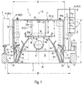
- the main parts or groups of parts generally designated 1 Recessed ceiling lights are the luminaire tray 2, a light distributor 3, which is is a light influencing agent, e.g. around a diffuser or a reflector with or without grid, several holding means 5 for releasably holding the recessed light in an installation opening 6, a ceiling 7 receiving the recessed ceiling light 1, e.g. a suspended ceiling, an operating device 8 for the electrical power supply Recessed ceiling light 1 and one or two sockets 9 for at least one lamp 11.
- the light distributor 3 or reflector is also with light carrier optics designated.
- the socket 9 or the sockets 9 are each on a socket body 9a, in particular made of electrically non-conductive material.
- the recessed ceiling light 1 of elongated shape, the lamp 11 being formed by a gas discharge tube can, the ends of which can be inserted in a socket 9 in the usual manner.
- the length of the lamp 11 is also the length of the recessed ceiling light fitting it 1 or luminaire tray 2 determined.
- the luminaire tray 2 a has a relatively small width B. With such a small width B that can Ballast or operating device 8 not on the side but only in the middle of the lamp tray 2 are arranged, whereby the height H of the downlight 1 is proportional is great.
- the lamp trough 2 has a square box with an open bottom arranged at the top of the trough floor 2a and four down from its edge extending sidewalls formed, the longitudinally extending sidewalls with 2b and the transversely extending side walls with end walls 2c are designated. At least on the free edges of the side walls 2b one by one can follow externally projecting bend formed edge part 2d in the form of an edge flange be provided that a horizontal in the present embodiment Edge leg 2e and an upright arranged on its free edge Edge legs 2f can have.
- the edge parts 2d can be the edge of the installation opening 6 reach under (not shown), or the width B1 of the lamp tray 2 including the edge parts 2d can be dimensioned so large that they are small Movement play fits into the installation opening 6.
- the light distributor 3 consists of a side reflector 3a and a head reflector 3b, which delimit a dome-shaped light distribution space 3c which is open on the underside, in the upper area of which the lamp 11 is arranged, and from which the light is down can radiate.
- the side reflector 3a consists of one another in a manner known per se opposite side reflector walls 3d, which may be in the bottom Area of the side reflector 3a arranged, consisting of transverse reflectors 3e Grids 3e form a structural unit which, from below, forms a lamp housing Lamp tray 2 can be inserted and in its fastening position by a detachable Quick-connect connection to the lamp tray 2 can be connected.
- the Recessed ceiling light 1 has an elongated shape, it is advantageous to use several To provide quick-connect connections that are distributed in the longitudinal direction are.
- four are in the end regions of the Recessed ceiling light 1 and laterally opposite one another Locking devices 12 are provided which automatically under a spring force engage so that the side reflector 3a when inserted from below into it Fixing position automatically locked.
- the locking devices 12 can be manually overpressed so that they can be released by a certain manual pull can be pushed over and opened for easy handling.
- Locking devices 12 are identical to one another and each have one laterally elastically bendable locking lug 14, which in a Locking recess or snaps elastically behind an undercut.
- the latching lug 14 is preferably made of one a flat ribbon existing spring arm 15 formed from the outside of the Reflector walls 3d extends upwards and a locking lug 14 forming has outward bend.
- the associated locking recess is formed by an undercut 16 which is above an inner shoulder 17 the associated side wall 2c is arranged and preferably by a U-shaped cut out and in an inwardly inclined upward position bent latching tongue 17a is formed.
- the back of the locking lug 14 can by a rounded or obliquely inwardly extending extension 18 of the Spring arm be formed. This or through the sloping inside of the Locking projection 17 is formed an insertion bevel, which when inserted of the side reflector 3a causes the latching lug 14 to bend automatically.
- the spring arm 15 can be the leg of an acute-angled spring angle, the another leg 19 arranged on the outside of the reflector wall 3d and fastened is, e.g. by means of rivets, not shown.
- the locking device 12 is located in the upwardly divergent space 21 between the side wall 2b and 3d reflector wall.
- the top reflector 3b forming an upper part of the light distributor 3 closes or covers the upper opening 4 of a lower part of the light distributor 3 forming Side reflector 3a.
- the head reflector 3b can be flat and e.g. through a flat sheet be formed by a vertically or obliquely angled its Longitudinal edges is stabilized.
- the head reflector 3b and / or the socket body 9a is or are in each case End region of the lamp tray 2 attached to a base 22 on the underside Trough bottom 2a is arranged and has a height a which is greater than that Height dimension b of the ballast or operating device 8, so that the latter between the head reflector 3b and the tub bottom 2a can be arranged, it being on Head reflector 3b or can be attached from the tub bottom 2a, e.g. means not illustrated screws.
- the operating device is 8 attached to the tub floor 2a, as shown in FIG. 1.
- the base 22 is connected in one piece to a wall of the lamp tray Tongue formed, which preferably starts in one piece from the associated end wall 2c and especially punched.
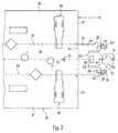
- a simple, quick and inexpensive manufacture the lamp trough 2 is present when it is made from the board 24 shown in FIG. 2 is preferably punched and bent in one operation.
- the board 24 has the Side walls 2b and end walls 2c as protruding from the tub floor 2a Blank sections, the around bent edges K1 indicated be angled, resulting in the square box shape.
- the tongue 23 is cut out of the end walls 2c by means of free cuts on both sides, the Exceeds end wall 2c and is preferably arranged in the center.
- the foot area of the Tongue 23 is located approximately in the middle of the end wall 2c.
- the end wall 2c consists of end wall strips 2c1, the length L of which mine is preferably dimensioned as the height of the side walls 2b.
- the trough shape can be formed by a pin and a groove receiving it Pin connection in the edge area between the end wall 2c and the to it adjacent side walls 2b may be provided.
- pin connection in the edge area between the end wall 2c and the to it adjacent side walls 2b may be provided.
- quadrangular pin projections 26 arranged in correspondingly shaped Bound recesses 27 in the facing edge region of the side walls 2b and can be attached therein, e.g. by welding, preferably by Spot welds.
- the end wall strips 2c1 are in the state of the strip extensions 2c2
- the board is extended by the one parallel to the associated bending line K1 Bending lines K2 are preferably folded inwards.
- the Strip extensions 2c2 is one or more holes 28 are arranged, which with in the end wall strips 2c1 arranged holes 29 in the folded position swear.
- the holes 28, 29 can be the frontal attachment of several in one Row arranged lamp trays 2 serve to form a light band.
- Lanyards can e.g. Screws or connectors may be provided that are made from Simplification reasons are not shown.
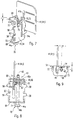
- the tongue 23 consists in the present embodiment of one of the associated end wall 2c outgoing first horizontal tongue legs 23a and an adjoining second, preferably vertical, tongue leg 23b, of which the tongue leg 23a around a transverse bending line K3 and the tongue leg 23b parallel to and between the tongue legs extending bending line K4 is bent or angled (Fig. 3).
- the tongue leg 23b extends to the bottom of the trough 2a and is free on it Fixed edge area.
- a preferably square recess 31 in the free edge area of the vertical tongue leg 23b, into which the head of a only 32 shown in Fig. 1, which fits into a prefabricated threaded hole 33 can be screwed into the tub floor 2a.
- the screw 32 In the completion of the tongue 23 is located the screw 32 on the inside of the vertical tongue leg 23b. By this attachment is the tongue leg 23b against lifting off from the tub floor 2a secured.
- the screw 32 can also have a positive limitation of the Tongue leg 23b against its in the longitudinal direction of the recessed ceiling light form directed movement inwards.
- a positive Limitation for the tongue leg 23b may be arranged on the tub floor 2a, the one Movement of the tongue leg 23b in the other longitudinal direction, that is one after limited to the outside or a movement away from the screw 32.
- such stabilization is formed by the fact that the tongue leg 23b in its free edge region, preferably in the center, one Approach 33 in the form of a short extension, which corresponds to a molded plug-in recess 35 in the tub bottom 2a.
- the socket body (s) 9a can be on the head reflector 3a or Base 22 may be attached, here on the horizontal tongue leg 23a.
- conventional socket bodies 9a are currently provided, which have a flange 9b at their foot end and with the socket body in a Plug-in recess can be used and by an appropriate distance from the flange 9b Arranged locking lugs 9c can be locked.
- In the present embodiment are with each other in each horizontal tongue leg 23a and in the head reflector 3b aligned, in particular rectangular, recesses provided, of which the in the tongue leg 23a plug-in recess is designated 36.
- the Associated socket body 9a is in from the inside of the tongue leg 23a the plug-in recess 36 can be inserted and locked by the locking lugs 9c.
- the socket body 9a is before the tongue is bent 23 inserted into this.
- the head reflector 3b can be plugged onto the protruding socket body 9a and be locked behind the locking lugs 9c, whereby the socket body 9a are locked.
- a plurality of holding means 5 are provided, which on both long sides of the Luminaire tray 2 are arranged. In the present embodiment are on everyone On the long side, two holding means 5 are arranged in the end regions of the lamp trough 2, preferably arranged offset inwards with respect to the associated base 22.
- the holding means 5 are arranged in mirror image with respect to the longitudinal center plane 13, where they can be mirror images or the same design. It is therefore in following the design and function of only one holding means 5 described because the other holding means 5 are comparable.
- the holding means 5 has a support arm 41 which is designed as a one-armed lever and freely pivotable about a vertical pivot axis 42 in a joint 43 which is arranged on the inside of the associated side wall 2b.
- the Pivot bearing 43 is formed by a hinge pin 44 which is in an inward direction directed distance from the side wall 2b is rotatably mounted.
- the holding means 5 is an adjusting device 45 for vertical adjustment of the Support arm 41 associated with the support arm 41 indirectly or directly vertically adjustable, namely movable up and down and in the respective adjustment position is noticeable.
- the adjusting device 45 has an adjusting member 46, which also arranged on the inside of the associated side wall 2b and from below with a Adjustment tool is accessible.
- the adjusting member 46 is preferably a Threaded screw formed with a rotary engagement element that with a non illustrated adjustment tool, e.g. a screwdriver that is rotatable.
- the adjustment device 45 is in the pivot bearing 43 integrated, the hinge pin 44 as having an external thread 48 Adjusting screw is formed on which the support arm 41 around the Pivot axis 42 can be pivoted and turned vertically by rotating the pivot pin 44 is adjustable.
- the support arm 41 can have an internal thread with which it is screwed onto the hinge pin 44.
- directions of movement are also sufficient if the engagement with the External thread of the hinge pin 44 takes place through a thin cutting edge, the secantial fits into the thread.
- the support arm 41 is on a carrier element 51 pivoted and preferably also vertically adjustable, these parts a Form preassembled unit, the outside of the side wall 2b in the area of a Recess 49 can be installed, which is located in the side wall 2b and up to the tub floor 2a can extend into it, in the area of the tub floor 2a can be tapered on one side to the support arm 41, as is e.g. 5, 7 and 9 demonstrate.
- a plug-in connection with a socket is preferably used for the attachment 52, into which the carrier element 51 can be inserted and in the inserted position a fixing device 53 can be fixed against an unwanted return movement.
- the recess 49 through which the Swivel bearing 43 with the associated section of the support arm 41 so is feasible that these parts in the assembled position inside of the side wall 2b are located, the recess 49 is also dimensioned so large that the support arm 41 its pivoting movements between a pivoted Ready position and a pivoted support position can perform. If the lamp trough 2 is so high that the support arm 41 is in his Adjustment area is located under the trough base 2a, then the recess 49 needs are only in the side wall 2b. If, on the other hand, the adjustment range is higher than the tub floor is 2a, then the recess must extend into the tub floor 2a Stretch in so that the support arm 41 can pivot in the support position S.
- the carrier element 51 has a plate-shaped one Base part 54, which can be connected to the side wall 2b by the jack 52.
- the socket 52 is designed so that the base part 54 in a lower Mounting position is attached to the side wall 2b and then upwards in one Guide is moved to its attachment position, being in the attachment position by means of Locking elements of the locking device 53 is locked.
- the jack 52 is on both sides of the Base part 54 arranged, upward-facing hook 55 and behind this Webs 56 formed, two on top of each other on both side edges of the base part protruding hooks 55 protrude inwards and upwards from the edges of the Recess 49 webs 56 protruding toward one another in the plug end position opposite.
- the webs 56 there are recesses 57 into which the Hooks 55 can be inserted in the plug-in start position, being between the stacked hooks 55 contact webs 58 on the side edges of the base part 54 are arranged, which are arranged vertically between the recesses 57 Contact webs 58 rest on the edge of the recess 49.
- the side edges 61 of the Recesses 57 and the hooks 55 form a vertical guide for displacement of the base part 54 or the carrier element 51 from its insertion start position into its Plug end position.
- the landing stages 58 are on one side or on both sides preferably two holes 62 arranged one above the other, formed in the on the base part 54 arranged and preferably cut free from the base part 54 and inwards engage bent tongues 63.
- the upper holes 62 are used for locking in the Plug end position.
- the lower holes 62 can also be used for locking in the Plug end position serve when an optional mounting of the support element 51 in different heights is desired.
- the lower holes 62 can also serve to place the support member 51 at the start of assembly so that the two tongues 63 are inserted into the two lower holes 62. So stick out the hooks 55 with their guide slots 55a far enough inward to the to engage behind the associated webs 56 or contact webs 58.
- the carrier element 51 then only needs to be pushed up so that the two tongues 63 in the Snap in the two upper holes 62 and the carrier element 51 on the side wall 2b fix.
- the support arm 41 is upright arranged wall or disc 64 formed on one side edge one laterally horizontally projecting bearing arm 65, which has a hole, in particular a Threaded hole on which the external thread of the hinge pin 44 is located.
- the bearing arm 65 is preferably by a tongue 66 which is separated and bent from the disk 64 formed, which is preferably U-shaped, with two bearing holes 65a in result in upper and lower legs of the tongue 66.
- a torsion spring 67 e.g.
- a spiral or Coil spring which with one of its legs the support arm 41 in the swung out Support position S biases so that the support arm 41 automatically from its pivoted into the ready position S1 in the support position S.
- the swivel movement is limited by a stop, e.g. as a result of that the bearing leg 65 abuts the base part 54.
- the distance c between the disc 64 and the pivot axis 42 is thus at the distance d between the pivot axis 42 adapted from the outside of the base part 54 that in the designated S1 pivoted ready position of the support arm 41 on or near the Base part 54 is located.
- the support arm 41 takes only one a small width, so that the recessed ceiling light 1 is easy to handle from below can be inserted into the installation opening 6. If the support arm 41 by a thin Washer 64 is formed, the construction is even more space-efficient.
- the support arm 41 is located with its horizontally inner end region, in which it is connected to the bearing leg 65 is, in the recess 49.
- the vertical dimension e of the supporting end portion of the support arm 41 Excess length formed, with several lines of weakness arranged one above the other 41a, e.g. Punchings or slots are provided on which the support section is easy to separate and can therefore be shortened.
- the pivot bearing 43 is through from the base part 54 inwardly projecting, preferably bent upper and lower base legs 68, 69 formed with aligned vertical holes 71, in which the Hinge pin is rotatably mounted.
- the head 44a of the hinge pin 44 is below arranged so that a rotary grip element 44b formed thereon, e.g. on Screwdriver slot is easily accessible from below.
- To secure of the hinge pin 44 against falling out is free at its upper Provided at the end a shoulder 72 which overlaps the upper base leg 68 and which, e.g. can be formed by a bruise.
- a locking means in the form of a locking or locking device 70 to be assigned to the S1 in the ready position so that the support arm 41st can be determined in the standby position S1 and the assembly by inserting can be done below without paying particular attention to the position of the support arm 41 have to riche.
- the locking lug 74 on the bearing arm 65 or on the lower leg of the tongue 66 so horizontally projecting that they in the Ready position S1 faces outwards and into the top edge of the base part arranged locking recess 75 is able to snap.
- the hinge pin 44 is axially displaceable, resulting in a corresponding axial distance f between the shoulder 72 and the base leg 68 or between the head 44 and the base leg 69 results.
- one Locking device 73 is thus the hinge pin 44 by the depth f Locking recess 75 mounted axially.
- the existing support arms 41 are used for mounting the recessed ceiling light 1 manually pivoted to its standby position and in the manner described above locked. Then the recessed ceiling light 1 can be handled easily in the Installation opening 6 are inserted into a position in which the edge parts 2d in the height of the edge of the installation opening 6. By a prescribed one Pressure from below on the hinge pin 44 can then support arms 41 automatically be pivoted into their support position S, in which they are above the ceiling 7 or Ceiling parts or support rails 7a for the ceiling 7 are located. If the Recessed ceiling light 1 is not at the correct height, this can by adjusting the height of the support arms 41 concerned by rotating the associated hinge pin 44 are brought about.
- the Recessed ceiling light 1 can be hung so high that with its underside cover with the ceiling or protrude downwards.
- the maximum distance from the ceiling 7 downwards is approximately determined by the height of the edge leg 2f.
- the recessed ceiling light 1 can also be adjusted or leveled in such a way that its underside an upward distance from the underside of the ceiling 7 having.
Landscapes
- Engineering & Computer Science (AREA)
- General Engineering & Computer Science (AREA)
- Non-Portable Lighting Devices Or Systems Thereof (AREA)
- Fastening Of Light Sources Or Lamp Holders (AREA)
Abstract
Description
- Fig. 1
- eine erfindungsgemäße Einbauleuchte im vertikalen Querschnitt;
- Fig. 2
- einen Endbereich eines Basisteils der Einbauleuchte, das in Form einer vorgefertigten Platine insbesondere als Stanzteil ausgebildet ist und zu einer Leuchtenwanne verformbar ist;
- Fig. 3
- den Endbereich nach Fig. 2 in Form einer Leuchtenwanne in perspektivischer Unteransicht;
- Fig. 4
- einen Teilbereich der Einbauleuchte mit der Leuchtenwanne und einem Trägerelement für den Abstützarm in dessen Montagestellung im vertikalen Schnitt;
- Fig. 5
- den Teilbereich nach Fig. 4 in perspektivischer Darstellung von innen;
- Fig. 6
- den Teilbereich nach Fig. 5 in perspektivischer Darstellung von außen;
- Fig. 7
- das Trägerelement mit einem Abstützarm als einzeln dargestellte Baueinheit in perspektivischer Ansicht von außen;
- Fig. 8
- das Trägerelement nach Fig. 7 in der Ansicht von innen;
- Fig. 9
- das Trägerelement nach Fig. 7 in der Draufsicht;
- Fig. 10
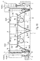
- eine erfindungsgemäße Leuchte in weiter abgewandelter Ausgestaltung im Querschnitt.
Claims (22)
- Deckeneinbauleuchte (1) mit einer Leuchtenwanne (2) mit mindestens einem seitlich auf die Leuchtenwanne aufgesetzten Trägerelement (51), welches einen um eine vertikale Schwenkachse (42) schwenkbaren Abstützarm (41) trägt, der durch eine Versteilvorrichtung (45) im wesentlichen vertikal verstellbar ist,
dadurch gekennzeichnet,
daß die Leuchtenwanne (2) im Bereich des Trägerelementes (51) eine Ausnehmung (49) aufweist, durch die ein die Schwenkachse (42) haltendes Teil des Trägerelementes (51) hindurchgreift, derart, daß die Schwenkachse (42) innerhalb der Leuchtenwanne (2) angeordnet ist. - Deckeneinbau leuchte nach Anspruch 1,
dadurch gekennzeichnet,
daß das Trägerelement (51) durch eine Steckverbindung mit der Leuchtenwanne (2) verbunden und in seiner in die Steckverbindung eingesteckten Position durch eine Fixiervorrichtung (53) fixierbar ist. - Deckeneinbauleuchte nach Anspruch 2,
dadurch gekennzeichnet,
daß die Steckverbindung durch Stege (56) an dem einen Teil und diesen hintergreifende Haken (55) an dem anderen Teil gebildet ist. - Deckeneinbauleuchte nach Anspruch 3,
dadurch gekennzeichnet,
daß die Haken (55) am Trägerelement (51) und die Stege (56) an der Leuchtenwanne (2) angeordnet sind. - Deckeneinbauleuchte nach Anspruch 4,
dadurch gekennzeichnet,
daß die Haken (55) an den seitlichen Rändern des Trägerelements (51) angeordnet sind und die Stege (56) an den seitlichen Rändern der Ausnehmung (49) angeordnet sind. - Deckeneinbauleuchte nach einem der vorherigen Ansprüche 2 bis 5,
dadurch gekennzeichnet,
daß die Fixiervorrichtung durch eine Verrastungsvorrichtung (60) gebildet ist. - Deckeneinbauleuchte nach Anspruch 6,
dadurch gekennzeichnet,
daß die Verrastungsvorrichtung (60) durch wenigstens eine vorzugsweise ausgebogene Zunge (63) am Trägerelement (51) und eine die Zunge (63) aufnehmende Verrastungsausnehmung (62) an der Leuchtenwanne (2) gebildet ist. - Deckeneinbauleuchte nach Anspruch 7,
dadurch gekennzeichnet,
daß zwei übereinander angeordnete Verrastungsausnehmungen (62) vorgesehen sind. - Deckeneinbauleuchte nach einem der vorherigen Ansprüche,
dadurch gekennzeichnet,
daß das Trägerelement (51) ein plattenförmiges Basisteil (54) aufweist. - Deckeneinbauleuchte nach einem der vorherigen Ansprüche,
dadurch gekennzeichnet,
daß der Abstützarm (41) durch eine etwa vertikale Scheibe (64) gebildet ist. - Deckeneinbauleuchte nach einem der vorherigen Ansprüche,
dadurch gekennzeichnet,
daß der Abstützarm (41) sich in einer eingeschwenkten Bereitschaftsstellung an oder in der Nähe der Leuchtenwanne (2) oder des Trägerelements (51) befindet. - Deckeneinbauleuchte nach einem der vorherigen Ansprüche,
dadurch gekennzeichnet,
daß die Schwenkachse (42) haltende Teil des Trägerelements (51) durch ein Schwenklager (43) gebildet ist. - Deckeneinbauleuchte nach Anspruch 12,
dadurch gekennzeichnet,
daß das Schwenklager (43) einen Gelenkbolzen (44) aufweist, und das Trägerelement (51) vorzugsweise mit einem oberen und einem unteren horizontalen Schenkel (68, 69) auf dem Gelenkbolzen (44) schwenkbar gelagert ist. - Deckeneinbauleuchte nach einem der vorherigen Ansprüche,
dadurch gekennzeichnet,
daß die Ausnehmung (49) sich in der Seitenwand (2b) und in der Bodenwand (2a) der Leuchtenwanne (2) befindet. - Deckeneinbauleuchte nach einem der vorherigen Ansprüche 12 bis 14,
dadurch gekennzeichnet,
daß die Verstellvorrichtung (45) in das Schwenklager (42) integriert ist. - Deckeneinbauleuchte nach Anspruch 15,
dadurch gekennzeichnet,
daß der Gelenkbolzen (44) ein Außengewinde aufweist und der Abstützarm (41) mit wenigstens einem Gewindeloch auf den Gelenkbolzen (44) aufgeschraubt ist. - Deckeneinbauleuchte nach einem der vorherigen Ansprüche,
dadurch gekennzeichnet,
daß der Abstützarm (41) in seiner eingeschwenkten Bereitschaftsstellung (S1) durch ein Feststellmittel (70) feststellbar und durch ein Entarretierungsmittel (76) entarretierbar ist. - Deckeneinbauleuchte nach einem der vorherigen Ansprüche,
dadurch gekennzeichnet,
daß der Abstützarm (41) durch die Kraft einer Feder (67) in seine Stützposition (S) beaufschlagt ist. - Deckeneinbauleuchte (1) mit einer Leuchtenwanne (2) mit mindestens einem seitlich auf die Leuchtenwanne aufgesetzten Trägerelement (51), welches einen um eine vorzugsweise vertikale Schwenkachse (42) zwischen einer Bereitschaftsposition (S1) und einer Stützposition (S) schwenkbaren Abstützarm (41) trägt, der durch eine Versteilvorrichtung (45) im wesentlich vertikal verstellbar ist,
dadurch gekennzeichnet,
elastische Versteilmittel, die den Abstützarm (41) in die Stützposition (S) zu drängen suchen, ferner durch Feststellmittel (70), mittels welchen der Abstützarm (41) entgegen der Wirkung der Versteilmittel in der Bereitschaftsposition (S1) arretierbar ist, und schließlich durch Entarretierungsmittel (76), mittels welchen so auf die Feststellmittel 70 eingewirkt werden kann, daß diese den Abstützarm (41) in der Bereitschaftsposition (S1) freigeben mit der Folge, daß der Abstützarm (41) durch die Verstellmittel in die Stützposition (s) geschwenkt wird. - Deckeneinbauleuchte nach einem der Ansprüche 17 bis 19,
dadurch gekennzeichnet,
daß das Feststellmittel (70) durch eine Verrastungsvorrichtung (73) gebildet ist. - Decken einbauleuchte nach Anspruch 20,
dadurch gekennzeichnet,
daß die Verrastungsvorrichtung (73) durch eine Verrastungsnase (74) und eine diese aufnehmende Rastausnehmung (75) gebildet ist, die zwischen dem Abstützarm (41) und dem Trägerelement (51) wirksam sind. - Deckeneinbauleuchte nach einem der Ansprüche 12 bis 21,
dadurch gekennzeichnet,
daß die Feststellmittel (70) durch eine axiale Verschiebung des Gelenkbolzens (44) vorzugsweise von unten nach oben lösbar sind.
Applications Claiming Priority (2)
| Application Number | Priority Date | Filing Date | Title |
|---|---|---|---|
| DE29819888U | 1998-11-06 | ||
| DE29819888U DE29819888U1 (de) | 1998-11-06 | 1998-11-06 | Deckeneinbauleuchte mit einer Leuchtenwanne und schwenkbaren Abstützarmen |
Publications (3)
| Publication Number | Publication Date |
|---|---|
| EP0999409A2 true EP0999409A2 (de) | 2000-05-10 |
| EP0999409A3 EP0999409A3 (de) | 2001-08-29 |
| EP0999409B1 EP0999409B1 (de) | 2006-09-20 |
Family
ID=8064995
Family Applications (1)
| Application Number | Title | Priority Date | Filing Date |
|---|---|---|---|
| EP99121564A Expired - Lifetime EP0999409B1 (de) | 1998-11-06 | 1999-10-29 | Deckeneinbauleuchte mit einer Leuchtenwanne und schwenkbaren Abstützarmen |
Country Status (4)
| Country | Link |
|---|---|
| EP (1) | EP0999409B1 (de) |
| AT (1) | ATE340335T1 (de) |
| DE (2) | DE29819888U1 (de) |
| ES (1) | ES2273456T3 (de) |
Cited By (2)
| Publication number | Priority date | Publication date | Assignee | Title |
|---|---|---|---|---|
| EP2472178A1 (de) | 2010-11-19 | 2012-07-04 | Zumtobel Lighting GmbH | Einbauleuchte |
| US10240761B2 (en) | 2015-09-28 | 2019-03-26 | Fischer Lighting Aps | Lamp housing with a locking device |
Families Citing this family (6)
| Publication number | Priority date | Publication date | Assignee | Title |
|---|---|---|---|---|
| DE102007036979A1 (de) | 2007-05-03 | 2008-11-06 | Zumtobel Lighting Gmbh | Befestigungselement für eine Einbauleuchte |
| DE202008003097U1 (de) * | 2008-03-05 | 2009-08-06 | Zumtobel Lighting Gmbh | Beleuchtungsanordnung mit Tragprofil |
| DE202008004325U1 (de) * | 2008-03-29 | 2009-08-06 | W + W Aufzugkomponenten Gmbh U. Co. Kg | Leuchte, insbesondere für Aufzugskabinen |
| DE102012111135A1 (de) * | 2012-11-19 | 2014-05-22 | Uwe Langer | Leuchte und Profilelement für eine Leuchte |
| DE202015105151U1 (de) * | 2015-09-30 | 2017-01-02 | Zumtobel Lighting Gmbh | Haltevorrichtung mit Tragschiene und Halteelement für die Tragschiene |
| EP3671041B1 (de) * | 2018-12-17 | 2024-05-22 | Electrolux Appliances Aktiebolag | Brennerkörper und haushaltsgerät mit einem brennerkörper und einer metallblechplatte |
Citations (1)
| Publication number | Priority date | Publication date | Assignee | Title |
|---|---|---|---|---|
| DE2802318A1 (de) | 1978-01-20 | 1979-07-26 | Trilux Lenze Gmbh & Co Kg | Befestigungsvorrichtung fuer eine deckeneinbauleuchte |
Family Cites Families (14)
| Publication number | Priority date | Publication date | Assignee | Title |
|---|---|---|---|---|
| US2914287A (en) * | 1957-06-07 | 1959-11-24 | Curtis Lighting Inc | Fixture and mounting bracket for same |
| US3018082A (en) * | 1958-10-27 | 1962-01-23 | Leonard G Berger | Light fixture mounting |
| US3018083A (en) * | 1959-04-24 | 1962-01-23 | Sunbeam Lighting Company | Automatic mounting means for a ceiling light fixture |
| US2973177A (en) * | 1960-01-14 | 1961-02-28 | Pittsburgh Reflector Company | Troffer side support |
| US3319919A (en) * | 1965-09-27 | 1967-05-16 | Solar Light Mfg Co | Mounting and leveling device for lighting fixtures |
| DE2263640A1 (de) * | 1972-12-27 | 1974-07-04 | Zeiss Ikon Ag | Riegel fuer deckeneinbauleuchten |
| DE2416887B2 (de) * | 1974-04-06 | 1977-02-24 | Trilux-Lenze Kg, 5770 Arnsberg | Befestigungsvorrichtung fuer eine deckeneinbauleuchte |
| DE2915545C2 (de) * | 1979-04-18 | 1983-12-08 | Trilux-Lenze Gmbh + Co Kg, 5760 Arnsberg | Vorrichtung zur Befestigung einer Deckeneinbauleuchte mit einem nach außen deckenparallel abgesetzten Befestigungsrand an Deckenträgern |
| DE3025149A1 (de) * | 1980-07-03 | 1982-01-28 | Licentia Patent-Verwaltungs-Gmbh, 6000 Frankfurt | Halteeinrichtung einer deckeneinbauleuchte |
| DE8301418U1 (de) * | 1983-01-20 | 1984-02-16 | Zeiss Ikon Ag, 7000 Stuttgart, De | Verstell- und halteeinrichtung fuer einbauleuchten |
| DE3329794A1 (de) * | 1983-08-18 | 1985-02-28 | Zeiss Ikon Ag, 7000 Stuttgart | Justier- und haltevorrichtung fuer deckeneinbauleuchten |
| EP0268283B1 (de) * | 1986-11-20 | 1993-05-26 | THORN LICHT GmbH | Deckeneinbauleuchte |
| DE19629901A1 (de) * | 1996-07-24 | 1998-01-29 | Zumtobel Licht | Einbauleuchte mit Haltemitteln in ihrer Halterung in einem Einbaukörper oder Haltemittel für eine solche Einbauleuchte |
| DE19715068A1 (de) * | 1997-04-11 | 1998-10-22 | Erco Leuchten | Einbauleuchte |
-
1998
- 1998-11-06 DE DE29819888U patent/DE29819888U1/de not_active Expired - Lifetime
-
1999
- 1999-10-29 ES ES99121564T patent/ES2273456T3/es not_active Expired - Lifetime
- 1999-10-29 EP EP99121564A patent/EP0999409B1/de not_active Expired - Lifetime
- 1999-10-29 DE DE59913857T patent/DE59913857D1/de not_active Expired - Lifetime
- 1999-10-29 AT AT99121564T patent/ATE340335T1/de active
Patent Citations (1)
| Publication number | Priority date | Publication date | Assignee | Title |
|---|---|---|---|---|
| DE2802318A1 (de) | 1978-01-20 | 1979-07-26 | Trilux Lenze Gmbh & Co Kg | Befestigungsvorrichtung fuer eine deckeneinbauleuchte |
Cited By (2)
| Publication number | Priority date | Publication date | Assignee | Title |
|---|---|---|---|---|
| EP2472178A1 (de) | 2010-11-19 | 2012-07-04 | Zumtobel Lighting GmbH | Einbauleuchte |
| US10240761B2 (en) | 2015-09-28 | 2019-03-26 | Fischer Lighting Aps | Lamp housing with a locking device |
Also Published As
| Publication number | Publication date |
|---|---|
| ES2273456T3 (es) | 2007-05-01 |
| DE59913857D1 (de) | 2006-11-02 |
| ATE340335T1 (de) | 2006-10-15 |
| EP0999409B1 (de) | 2006-09-20 |
| DE29819888U1 (de) | 2000-03-16 |
| EP0999409A3 (de) | 2001-08-29 |
Similar Documents
| Publication | Publication Date | Title |
|---|---|---|
| EP0796411B1 (de) | Einbauleuchte | |
| EP0912861B1 (de) | Adapter für ein haltemittel, welches zum befestigen einer einbauleuchte in einer einbauöffnung bestimmt ist, oder haltemittel oder einbauleuchte mit einem solchen adapter | |
| EP1534101A1 (de) | TISCH, INSBESONDERE BüRO- UND KONFERENZTISCH | |
| DE10145499A1 (de) | Lichtkanalsystem | |
| EP0297400A1 (de) | Büro-Arbeitsplatz | |
| AT520220B1 (de) | Montageträger zur Montage von Oberschienen | |
| EP0999409B1 (de) | Deckeneinbauleuchte mit einer Leuchtenwanne und schwenkbaren Abstützarmen | |
| EP0999410B1 (de) | Blech-Trägerteil für eine Leuchte | |
| EP0947765B1 (de) | Vorrichtung zum Befestigen einer Deckeneinbauleuchte | |
| EP0912860B1 (de) | Einbauleuchte mit haltemitteln zu ihrer halterung in einem einbaukörper oder haltemittel für eine solche einbauleuchte | |
| DE19802376C2 (de) | Anordnung von mindestens zwei aneinander stoßenden gleichartigen Leuchten zu einem Lichtband und Positionierelement dafür | |
| EP0268283B1 (de) | Deckeneinbauleuchte | |
| EP2339227A2 (de) | Anbauleuchte | |
| DE2915545A1 (de) | Vorrichtung zur befestigung einer einbauleuchte mit einem aeusseren deckenparallel abgesetzten rand in einer abgehaengten decke | |
| DE102004006970B4 (de) | Einbauleuchte mit einer Fixiervorrichtung zu ihrer Fixierung in einer Einbauöffnung | |
| EP1267119A2 (de) | Leuchte, insbesondere Anbauleuchte | |
| DE19755996C2 (de) | Einbauvorrichtung für eine Deckenleuchte in eine Zwischendecke | |
| DE29901397U1 (de) | Längliche, im Querschnittsprofil linsenartige Pendel- oder Anbauleuchte | |
| DE2043131A1 (de) | Lampenhalterungen | |
| EP0268282A2 (de) | Leuchte | |
| DE19713818A1 (de) | Adapter für ein Haltemittel, welches zum Befestigen einer Einbauleuchte in einer Einbauöffnung bestimmt ist, oder Haltemittel oder Einbauleuchte mit einem solchen Adapter | |
| EP0735312A1 (de) | Werferleuchte für ein sekundäres Innenbeleuchtungssystem | |
| DE19820444A1 (de) | Federnde Gas-Brenner-Lagerung | |
| DE3739076A1 (de) | Deckeneinbauleuchte | |
| DE8328052U1 (de) | Befestigungsanordnung fuer an decken anzubringende leuchtengehaeuse |
Legal Events
| Date | Code | Title | Description |
|---|---|---|---|
| PUAI | Public reference made under article 153(3) epc to a published international application that has entered the european phase |
Free format text: ORIGINAL CODE: 0009012 |
|
| AK | Designated contracting states |
Kind code of ref document: A2 Designated state(s): AT BE CH CY DE DK ES FI FR GB GR IE IT LI LU MC NL PT SE |
|
| AX | Request for extension of the european patent |
Free format text: AL;LT;LV;MK;RO;SI |
|
| PUAL | Search report despatched |
Free format text: ORIGINAL CODE: 0009013 |
|
| AK | Designated contracting states |
Kind code of ref document: A3 Designated state(s): AT BE CH CY DE DK ES FI FR GB GR IE IT LI LU MC NL PT SE |
|
| AX | Request for extension of the european patent |
Free format text: AL;LT;LV;MK;RO;SI |
|
| 17P | Request for examination filed |
Effective date: 20020220 |
|
| AKX | Designation fees paid |
Free format text: AT BE CH CY DE DK ES FI FR GB GR IE IT LI LU MC NL PT SE |
|
| GRAP | Despatch of communication of intention to grant a patent |
Free format text: ORIGINAL CODE: EPIDOSNIGR1 |
|
| RAP1 | Party data changed (applicant data changed or rights of an application transferred) |
Owner name: ZUMTOBEL LIGHTING GMBH |
|
| GRAS | Grant fee paid |
Free format text: ORIGINAL CODE: EPIDOSNIGR3 |
|
| GRAA | (expected) grant |
Free format text: ORIGINAL CODE: 0009210 |
|
| AK | Designated contracting states |
Kind code of ref document: B1 Designated state(s): AT BE CH CY DE DK ES FI FR GB GR IE IT LI LU MC NL PT SE |
|
| PG25 | Lapsed in a contracting state [announced via postgrant information from national office to epo] |
Ref country code: IT Free format text: LAPSE BECAUSE OF FAILURE TO SUBMIT A TRANSLATION OF THE DESCRIPTION OR TO PAY THE FEE WITHIN THE PRESCRIBED TIME-LIMIT;WARNING: LAPSES OF ITALIAN PATENTS WITH EFFECTIVE DATE BEFORE 2007 MAY HAVE OCCURRED AT ANY TIME BEFORE 2007. THE CORRECT EFFECTIVE DATE MAY BE DIFFERENT FROM THE ONE RECORDED. Effective date: 20060920 Ref country code: IE Free format text: LAPSE BECAUSE OF FAILURE TO SUBMIT A TRANSLATION OF THE DESCRIPTION OR TO PAY THE FEE WITHIN THE PRESCRIBED TIME-LIMIT Effective date: 20060920 Ref country code: FI Free format text: LAPSE BECAUSE OF FAILURE TO SUBMIT A TRANSLATION OF THE DESCRIPTION OR TO PAY THE FEE WITHIN THE PRESCRIBED TIME-LIMIT Effective date: 20060920 |
|
| REG | Reference to a national code |
Ref country code: GB Ref legal event code: FG4D Free format text: NOT ENGLISH |
|
| REG | Reference to a national code |
Ref country code: CH Ref legal event code: NV Representative=s name: A. BRAUN, BRAUN, HERITIER, ESCHMANN AG PATENTANWAE Ref country code: CH Ref legal event code: EP |
|
| PG25 | Lapsed in a contracting state [announced via postgrant information from national office to epo] |
Ref country code: MC Free format text: LAPSE BECAUSE OF NON-PAYMENT OF DUE FEES Effective date: 20061031 |
|
| REG | Reference to a national code |
Ref country code: IE Ref legal event code: FG4D Free format text: LANGUAGE OF EP DOCUMENT: GERMAN |
|
| REF | Corresponds to: |
Ref document number: 59913857 Country of ref document: DE Date of ref document: 20061102 Kind code of ref document: P |
|
| GBT | Gb: translation of ep patent filed (gb section 77(6)(a)/1977) |
Effective date: 20061129 |
|
| PG25 | Lapsed in a contracting state [announced via postgrant information from national office to epo] |
Ref country code: SE Free format text: LAPSE BECAUSE OF FAILURE TO SUBMIT A TRANSLATION OF THE DESCRIPTION OR TO PAY THE FEE WITHIN THE PRESCRIBED TIME-LIMIT Effective date: 20061220 Ref country code: DK Free format text: LAPSE BECAUSE OF FAILURE TO SUBMIT A TRANSLATION OF THE DESCRIPTION OR TO PAY THE FEE WITHIN THE PRESCRIBED TIME-LIMIT Effective date: 20061220 |
|
| PG25 | Lapsed in a contracting state [announced via postgrant information from national office to epo] |
Ref country code: PT Free format text: LAPSE BECAUSE OF FAILURE TO SUBMIT A TRANSLATION OF THE DESCRIPTION OR TO PAY THE FEE WITHIN THE PRESCRIBED TIME-LIMIT Effective date: 20070312 |
|
| REG | Reference to a national code |
Ref country code: IE Ref legal event code: FD4D |
|
| REG | Reference to a national code |
Ref country code: ES Ref legal event code: FG2A Ref document number: 2273456 Country of ref document: ES Kind code of ref document: T3 |
|
| EN | Fr: translation not filed | ||
| PLBE | No opposition filed within time limit |
Free format text: ORIGINAL CODE: 0009261 |
|
| STAA | Information on the status of an ep patent application or granted ep patent |
Free format text: STATUS: NO OPPOSITION FILED WITHIN TIME LIMIT |
|
| 26N | No opposition filed |
Effective date: 20070621 |
|
| PG25 | Lapsed in a contracting state [announced via postgrant information from national office to epo] |
Ref country code: GR Free format text: LAPSE BECAUSE OF FAILURE TO SUBMIT A TRANSLATION OF THE DESCRIPTION OR TO PAY THE FEE WITHIN THE PRESCRIBED TIME-LIMIT Effective date: 20061221 Ref country code: FR Free format text: LAPSE BECAUSE OF FAILURE TO SUBMIT A TRANSLATION OF THE DESCRIPTION OR TO PAY THE FEE WITHIN THE PRESCRIBED TIME-LIMIT Effective date: 20070518 |
|
| REG | Reference to a national code |
Ref country code: CH Ref legal event code: PFA Owner name: ZUMTOBEL LIGHTING GMBH Free format text: ZUMTOBEL LIGHTING GMBH#SCHWEIZER STRASSE 30#6850 DORNBIRN (AT) -TRANSFER TO- ZUMTOBEL LIGHTING GMBH#SCHWEIZER STRASSE 30#6850 DORNBIRN (AT) |
|
| PG25 | Lapsed in a contracting state [announced via postgrant information from national office to epo] |
Ref country code: LU Free format text: LAPSE BECAUSE OF NON-PAYMENT OF DUE FEES Effective date: 20061029 |
|
| PG25 | Lapsed in a contracting state [announced via postgrant information from national office to epo] |
Ref country code: FR Free format text: LAPSE BECAUSE OF FAILURE TO SUBMIT A TRANSLATION OF THE DESCRIPTION OR TO PAY THE FEE WITHIN THE PRESCRIBED TIME-LIMIT Effective date: 20060920 Ref country code: CY Free format text: LAPSE BECAUSE OF FAILURE TO SUBMIT A TRANSLATION OF THE DESCRIPTION OR TO PAY THE FEE WITHIN THE PRESCRIBED TIME-LIMIT Effective date: 20060920 |
|
| PGFP | Annual fee paid to national office [announced via postgrant information from national office to epo] |
Ref country code: NL Payment date: 20131023 Year of fee payment: 15 Ref country code: BE Payment date: 20131128 Year of fee payment: 15 |
|
| REG | Reference to a national code |
Ref country code: CH Ref legal event code: PCAR Free format text: NEW ADDRESS: HOLBEINSTRASSE 36-38, 4051 BASEL (CH) |
|
| PGFP | Annual fee paid to national office [announced via postgrant information from national office to epo] |
Ref country code: ES Payment date: 20141127 Year of fee payment: 16 |
|
| PGFP | Annual fee paid to national office [announced via postgrant information from national office to epo] |
Ref country code: AT Payment date: 20141028 Year of fee payment: 16 |
|
| REG | Reference to a national code |
Ref country code: NL Ref legal event code: V1 Effective date: 20150501 |
|
| PG25 | Lapsed in a contracting state [announced via postgrant information from national office to epo] |
Ref country code: BE Free format text: LAPSE BECAUSE OF NON-PAYMENT OF DUE FEES Effective date: 20141031 |
|
| PG25 | Lapsed in a contracting state [announced via postgrant information from national office to epo] |
Ref country code: NL Free format text: LAPSE BECAUSE OF NON-PAYMENT OF DUE FEES Effective date: 20150501 |
|
| PGFP | Annual fee paid to national office [announced via postgrant information from national office to epo] |
Ref country code: GB Payment date: 20151030 Year of fee payment: 17 Ref country code: CH Payment date: 20151023 Year of fee payment: 17 |
|
| PGFP | Annual fee paid to national office [announced via postgrant information from national office to epo] |
Ref country code: DE Payment date: 20151230 Year of fee payment: 17 |
|
| REG | Reference to a national code |
Ref country code: AT Ref legal event code: MM01 Ref document number: 340335 Country of ref document: AT Kind code of ref document: T Effective date: 20151029 |
|
| PG25 | Lapsed in a contracting state [announced via postgrant information from national office to epo] |
Ref country code: AT Free format text: LAPSE BECAUSE OF NON-PAYMENT OF DUE FEES Effective date: 20151029 |
|
| REG | Reference to a national code |
Ref country code: ES Ref legal event code: FD2A Effective date: 20161125 |
|
| PG25 | Lapsed in a contracting state [announced via postgrant information from national office to epo] |
Ref country code: ES Free format text: LAPSE BECAUSE OF NON-PAYMENT OF DUE FEES Effective date: 20151030 |
|
| REG | Reference to a national code |
Ref country code: DE Ref legal event code: R119 Ref document number: 59913857 Country of ref document: DE |
|
| REG | Reference to a national code |
Ref country code: CH Ref legal event code: PL |
|
| GBPC | Gb: european patent ceased through non-payment of renewal fee |
Effective date: 20161029 |
|
| PG25 | Lapsed in a contracting state [announced via postgrant information from national office to epo] |
Ref country code: LI Free format text: LAPSE BECAUSE OF NON-PAYMENT OF DUE FEES Effective date: 20161031 Ref country code: GB Free format text: LAPSE BECAUSE OF NON-PAYMENT OF DUE FEES Effective date: 20161029 Ref country code: CH Free format text: LAPSE BECAUSE OF NON-PAYMENT OF DUE FEES Effective date: 20161031 Ref country code: DE Free format text: LAPSE BECAUSE OF NON-PAYMENT OF DUE FEES Effective date: 20170503 |