EP0996791B1 - Antriebsvorrichtung für eine sperrschranke - Google Patents
Antriebsvorrichtung für eine sperrschranke Download PDFInfo
- Publication number
- EP0996791B1 EP0996791B1 EP97932835A EP97932835A EP0996791B1 EP 0996791 B1 EP0996791 B1 EP 0996791B1 EP 97932835 A EP97932835 A EP 97932835A EP 97932835 A EP97932835 A EP 97932835A EP 0996791 B1 EP0996791 B1 EP 0996791B1
- Authority
- EP
- European Patent Office
- Prior art keywords
- gear
- drive
- crank
- shaft
- drive device
- Prior art date
- Legal status (The legal status is an assumption and is not a legal conclusion. Google has not performed a legal analysis and makes no representation as to the accuracy of the status listed.)
- Expired - Lifetime
Links
Images





Classifications
-
- E—FIXED CONSTRUCTIONS
- E01—CONSTRUCTION OF ROADS, RAILWAYS, OR BRIDGES
- E01F—ADDITIONAL WORK, SUCH AS EQUIPPING ROADS OR THE CONSTRUCTION OF PLATFORMS, HELICOPTER LANDING STAGES, SIGNS, SNOW FENCES, OR THE LIKE
- E01F13/00—Arrangements for obstructing or restricting traffic, e.g. gates, barricades ; Preventing passage of vehicles of selected category or dimensions
- E01F13/04—Arrangements for obstructing or restricting traffic, e.g. gates, barricades ; Preventing passage of vehicles of selected category or dimensions movable to allow or prevent passage
- E01F13/06—Arrangements for obstructing or restricting traffic, e.g. gates, barricades ; Preventing passage of vehicles of selected category or dimensions movable to allow or prevent passage by swinging into open position about a vertical or horizontal axis parallel to the road direction, i.e. swinging gates
-
- Y—GENERAL TAGGING OF NEW TECHNOLOGICAL DEVELOPMENTS; GENERAL TAGGING OF CROSS-SECTIONAL TECHNOLOGIES SPANNING OVER SEVERAL SECTIONS OF THE IPC; TECHNICAL SUBJECTS COVERED BY FORMER USPC CROSS-REFERENCE ART COLLECTIONS [XRACs] AND DIGESTS
- Y10—TECHNICAL SUBJECTS COVERED BY FORMER USPC
- Y10T—TECHNICAL SUBJECTS COVERED BY FORMER US CLASSIFICATION
- Y10T74/00—Machine element or mechanism
- Y10T74/19—Gearing
- Y10T74/19642—Directly cooperating gears
- Y10T74/19698—Spiral
- Y10T74/19828—Worm
-
- Y—GENERAL TAGGING OF NEW TECHNOLOGICAL DEVELOPMENTS; GENERAL TAGGING OF CROSS-SECTIONAL TECHNOLOGIES SPANNING OVER SEVERAL SECTIONS OF THE IPC; TECHNICAL SUBJECTS COVERED BY FORMER USPC CROSS-REFERENCE ART COLLECTIONS [XRACs] AND DIGESTS
- Y10—TECHNICAL SUBJECTS COVERED BY FORMER USPC
- Y10T—TECHNICAL SUBJECTS COVERED BY FORMER US CLASSIFICATION
- Y10T74/00—Machine element or mechanism
- Y10T74/21—Elements
- Y10T74/2186—Gear casings
Definitions
- the invention relates to a drive device for a barrier or a similar locking or closing device, such as this, for example in EP 0 290 957 B1, 0 438 364 B1, DE-U-85 16 062, DE 32 31 720 C1 or DE 83 00 704 U1 are described.
- the invention is based on such a device with a drive unit on which the drive motor and an at least one-stage connected to it Reduction worm and / or spur gear with an articulated connection to a swivel crank on one preferably a horizontal one on both sides
- Axis swiveling drive shaft having a fastening for that usually by about 90 degrees pivoting locking or closing element or the barrier boom as well as with abutments for those who attack their spring crank Compensating springs is provided.
- drive devices exist fixed components as well as the movable drive and Gear elements from a variety of individual parts.
- This variety of parts is perceived as disadvantageous, because already in the parts procurement on the different Design variants should be considered, and because during the assembly and adjustment of the numerous individual parts a considerable amount of work has to be done.
- DE 85 16 062 discloses features of a non-reversible motor and a 45 degree slant that is not moving in parallel planes, crank mechanism provided with a connecting rod-like bolt.
- a very significant disadvantage is that depending on the local conditions at the place of use very different construction sizes, different drive powers and different types of training, for example Right or left barrier arrangement necessary are.
- the object of the invention is derived from these similarities to that extent, a construction of such a drive device to create a much smaller one Number of individual components, and the especially uniform for different drive powers and barrier lengths and weights and for legal or Left arrangement of the barrier boom always in the same version and construction is usable.
- this one-piece and one-piece drive housing it is made possible with the claimed features a compact construction unit of the drive device to create, consisting of the drive motor, the encapsulated Reduction gear, a lever drive with an output crank, Articulated connection to the swivel crank, and with bearings the drive shaft for the locking or closing element or the barrier tree.
- This construction unit is exposed on all sides flat mounting flange strips equipped, and therefore can it on any designed substructures or other Holding structures can be attached or anchored.
- the spatial inclusion of one is particularly advantageous Mounting flange for fastening the drive motor in combination with the gear box for the reduction gear. Due to the mechanical processing of both devices in one setup can be processed in the shortest possible time narrowest tolerance values are observed.
- This mounting flange for attaching the drive motor can be circular cylindrical, transverse to the drive shaft aligned pipe neck be formed, in which the stator housing of the electric motor is inserted.
- the receiving flange as a short pipe socket with a circular one Centering approach is formed on which the drive motor stator housing is appropriately applied and screwed.
- the reduction gear is in the manner of a Modular system consisting of a worm and two spur gear stages formed, the translations of the snail and the spur gear stages by exchanging pairs of gears Limits variable combinations of reduction ratios allow.
- the output crank on the outside of the gearbox is included a handlebar lever articulated to the swivel crank, and this sits on the drive shaft for the barrier or the other locking device.
- This drive shaft is supported on both sides in bearing blocks, which are attached to the drive housing are molded.
- On the one side exposed Drive shaft is by means of a fastening device the barrier boom or other locking device is connected.
- cranks on the gearbox output shaft and also especially the swivel crank on the drive shaft Clamping effect are attached.
- the cranks are divided Ring flanges detachable by means of screw connections on the Drive shaft clamped.
- To lock the working shaft serves a securing element, which after loosening the screw connection removed and after the side swap of the working wave reinserted and by tightening the screw connection is fixed.
- the drive device according to the invention unites opposite the state of the art several complementary measures to a very advanced new technical Solution. This makes it possible to reduce significantly technical effort by limitation to one reduced number of components using a modular concept for a variety of different Use cases easily adjustable barriers or the like. Locking or closing devices create.
- Figure 1 is a basic form of one-piece and one-piece Drive housing G shown. It essentially exists from a rectangular base frame 1, with flat mounting flange strips surrounding it on all sides 2 is provided; these have a number of locally distributed ones Bores 3, which are embedded in hole reinforcements 4 are. Opposite each other are by means of reinforcing ribs 5 two bearing blocks 6 for mounting the drive shaft molded. Also the rectangular base frame 1 provided in the edge areas R with reinforcing ribs 7, and by further continuous reinforcing ribs 8 the edge regions R are connected to one another in a torsionally rigid manner, with free openings A between the reinforcing ribs, B and C are present.
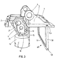
- FIG. 3 shows the drive housing according to FIG. 2 with a on this frame 49 arranged from two side walls 50 and a frame bracket 51 for hanging in FIG. 11 shown compensation springs 48.
- the frame 49 can be integrally connected to the drive housing G, e.g. as a single injection molded part, or it can also be by means of a plug or screw connection connected to this his.
- the gear box 9 has an inlet connector 18 for insertion the motor shaft on which in the embodiment a snail, not shown here, sits.
- the bearings 20 and 20a with axis A2 serve to accommodate the Rolling bearing for the second countershaft with a gear and another pinion, and the bearings 21 and 21a with axis A3 take the roller bearings for the transmission output shaft on, which carries a spur gear in the gearbox 9 and protrudes through the outlet pipe 21b and there with the output crank is provided.
- the gear cover 10 is also provided with an extension 23 which has a stop buffer 24 helps to limit the movement of the Output crank 31 is used.
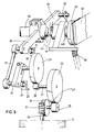
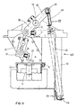
- 9 to 11 show the drive kinematics of the device of the illustrated embodiment.
- 9 is the motor shaft of the drive motor 17 denoted by 36 can be seen, on which the screw 32 sits.
- the handlebar lever 37 the torque is transmitted to the pivot crank 38, which is connected to the drive shaft 46.
- This is formed as a hollow shaft in which the working shaft 44th removably arranged and rotatably detachable with this connected is.
- the fastening device sits on the working shaft 44 40 for the barrier boom 41.
- the pivot crank 38 shows the spring crank 45, to which the upper spring cross member 42 is attached, the serves to hang the compensating springs 48.
Landscapes
- Engineering & Computer Science (AREA)
- Architecture (AREA)
- Civil Engineering (AREA)
- Structural Engineering (AREA)
- Gear Transmission (AREA)
- Power-Operated Mechanisms For Wings (AREA)
- Electrical Discharge Machining, Electrochemical Machining, And Combined Machining (AREA)
- Vending Machines For Individual Products (AREA)
- Refuge Islands, Traffic Blockers, Or Guard Fence (AREA)
- General Details Of Gearings (AREA)
- Auxiliary Devices For And Details Of Packaging Control (AREA)
- Connection Of Motors, Electrical Generators, Mechanical Devices, And The Like (AREA)
- Transmission Devices (AREA)
- Road Signs Or Road Markings (AREA)
- Jib Cranes (AREA)
- Forklifts And Lifting Vehicles (AREA)
- Road Repair (AREA)
- Soil Working Implements (AREA)
Description
- Fig. 1
- die perspektivische Ansicht einer Grundform des Antriebsgehäuses in einer ersten Ausführung;
- Fig. 2
- die Grundform gemäss Fig. 1 in einer anderen perspektivischer Ansicht;
- Fig. 3
- die Grundform gemäss Fig. 2 in einer zweiten Ausführungsform in perspektivischer Ansicht;
- Fig. 4
- die Grundform gemäss Fig. 1 in Seitenansicht;
- Fig. 5
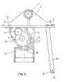
- die Grundform gemäss Fig. 4 in einer weiteren Ausführungsform;
- Fig. 6
- den Getriebedeckel in Seitenansicht;
- Fig. 7
- den Getriebedeckel im Schnitt;
- Fig. 8
- den Getriebedeckel von der Innenseite;
- Fig. 9
- eine schematische Darstellung der Antriebskinematik;
- Fig. 10
- das Antriebsgetriebe im Teilschnitt;
- Fig. 11
- das Antriebsgetriebe in Seitenansicht.
Claims (12)
- Antriebsvorrichtung für eine Sperrschranke oder eine dgl. Sperr- oder Schliessvorrichtung mit einem Antriebs-Aggregat, welches einen Antriebsmotor (17) und ein an diesen angeschlossenes wenigstens einstufiges Untersetzungs-Schnecken- und/oder Stirnradgetriebe mit einer Gelenkverbindung zu einer Schwenkkurbel (38) an einer in beidseitigen Lagerstellen vorzugsweise eine horizontale Achse schwenkbaren Antriebswelle (46) aufweist, die mit einer Befestigungsvorrichtung (40) für das in der Regel um etwa 90 Winkelgrad zu schwenkende Sperr- oder Schliess-Element bzw. den Schrankenbaum (41) sowie mit Widerlagern für die an ihrer Federkurbel (45) angreifenden Ausgleichsfedern (48) versehen ist,
gekennzeichnet durcha) ein einteiliges und einstückiges Antriebsgehäuse (G) mit allseitig freiliegenden ebenen Befestigungs-Flanschleisten (2), welches fernerb) einen Aufnahme-Flansch (14) zum Befestigen des ausbau-bzw. abnehmbaren Antriebsmotors (17) aufweist, dessen Motorwelle (36) inc) einen mit einem Getriebedeckel (10) abschliessbaren, ein Untersetzungsgetriebe enthaltenden Getriebekasten (9) hineingeführt ist,d) an dessen Getriebe-Abtriebswelle (30) eine Abtriebskurbel (31) befestigt ist, welchee) mittels eines Lenkerhebels (37) mit der Schwenkkurbel (38) der Antriebswelle (46) in gelenkiger Verbindung steht, welchef) in zwei an das einstückige Antriebsgehäuse (G) angeformten Lagerböcken (6) beidseitig gelagert undg) mindestens im Bereich einer Lagerstelle einseitig herausgeführt und mit der Befestigungsvorrichtung (40) für das Sperr- oder Schliess-Element bzw. den Schrankenbaum (41) versehen ist. - Antriebsvorrichtung nach Anspruch 1, gekennzeichnet durch zwei an das Antriebsgehäuse (G) beidseitig angeformte stabförmige, mittels eines Gestellbügels (51) in Querrichtung verbundene Seitenwangen (50), an denen eine untere Federtraverse (54) für die Ausgleichsfedern (48) angeordnet ist.
- Antriebsvorrichtung nach den Ansprüchen 1 oder 2, dadurch gekennzeichnet, dass der Anfnahme-Flansch (14) zum Befesigen des Antriebsmotors (17) als kreiszylindrischer, queraxial zur Antriebswelle (46) ausgerichteter Rohransatz geformt ist.
- Antriebsvorrichtung nach Anspruch 3, dadurch gekennzeichnet, dass in den Rohransatz des Aufnahme-Flansches (14) der Antriebsmotor mit seinem Statorgehäuse eingesetzt ist.
- Antriebsvorrichtung nach Anspruch 3, dadurch gekennzeichnet, dass der Rohransatz des Aufnahme-Flansches (14) als kurzer Rohrstutzen geformt und mit einem kreisförmigen Zentrier-Ansatz (47) zur Aufnahme des Antriebsmotor-Statorgehäuses (17) versehen ist.
- Antriebsvorrichtung nach den Ansprüchen 1 oder 2, dadurch gekennzeichnet, dass der Getriebekasten (9) mit einem Eingangsstutzen (18) für die Motorwelle (36), mit den Vorgelegerädern und zugehörigen Lagerstellen für wenigstens eine Untersetzungsstufe, und dass der Getriebedeckel (10) mit einem Ausgangsstutzen (21b) für die fliegend gelagerte, mit einer Abtriebskurbel (31) versehene Getriebe-Abtriebswelle (30) versehen ist.
- Antriebsvorrichtung nach den Ansprüchen 1 oder 2, dadurch gekennzeichnet, dass in der mit der Schwenkkurbel (38) verbundenen als Hohlwelle ausgebildeten Antriebswelle (46) eine ebenfalls mit der Schwenkkurbel (38) drehfest, jedoch lösbar verbundene, axialverschiebbare Arbeitswelle (44) angeordnet ist, an welcher die Befestigungsvorrichtung (40) für das Sperr- oder Schliess-Element bzw. den Schrankenbaum (41) drehfest befestigt ist.
- Antriebsvorrichtung nach Anspruch 6, dadurch gekennzeichnet, dass die Abtriebskurbel (31) auf der Getriebe-Abtriebswelle (30) mittels Klemmwirkung befestigt ist.
- Antriebsvorrichtung nach Anspruch 7, dadurch gekennzeichnet, dass die Schwenkkurbel (38) auf der Antriebswelle (46) mittels Klemmwirkung befestigt ist.
- Antriebsvorrichtung nach den Ansprüchen 1 oder 2, dadurch gekennzeichnet, dass eine obere Federtraverse (42) für die Ausgleichsfedern (48) gelenkig mit einem auf der Antriebswelle (46) befestigten Federkurbel (45) verbunden ist.
- Antriebsvorrichtung nach den Ansprüchen 1 oder 2, dadurch gekennzeichnet, dass eine untere Federtraverse (53, 54) für die Ausgleichsfedern (48) an einem Gestellrahmen (49) des Antriebsgehäuses (G) befestigt ist.
- Antriebsvorrichtung nach den Ansprüchen 1 oder 2, dadurch gekennzeichnet, dass das Untersetzungsgetriebe in dem Getriebekasten (9) aus einer ersten Untersetzungsstufe mit der auf der Motorwelle (36) sitzenden Schnecke (32) und dem Schneckenrad (34) besteht, und dass die zweite Untersetzungstufe aus einem ersten Zahnritzel I (35) und einem ersten Stirnrad I (26) gebildet ist, und dass die dritte Untersetzungsstufe ein zweites Zahnritzel II (28) und ein zweites Stirnrad II (29) umfasst, das auf der Getriebe-Abtriebswelle (30) sitzt, auf welcher die Abtriebskurbel (31) festgeklemmt ist.
Applications Claiming Priority (1)
| Application Number | Priority Date | Filing Date | Title |
|---|---|---|---|
| PCT/EP1997/003821 WO1999004100A1 (de) | 1997-07-17 | 1997-07-17 | Antriebsvorrichtung für eine sperrschranke |
Publications (2)
| Publication Number | Publication Date |
|---|---|
| EP0996791A1 EP0996791A1 (de) | 2000-05-03 |
| EP0996791B1 true EP0996791B1 (de) | 2001-06-27 |
Family
ID=8166691
Family Applications (1)
| Application Number | Title | Priority Date | Filing Date |
|---|---|---|---|
| EP97932835A Expired - Lifetime EP0996791B1 (de) | 1997-07-17 | 1997-07-17 | Antriebsvorrichtung für eine sperrschranke |
Country Status (17)
| Country | Link |
|---|---|
| US (1) | US6272943B1 (de) |
| EP (1) | EP0996791B1 (de) |
| JP (1) | JP3223187B2 (de) |
| KR (1) | KR100470280B1 (de) |
| AT (1) | ATE202606T1 (de) |
| AU (1) | AU730907B2 (de) |
| BR (1) | BR9714550A (de) |
| CA (1) | CA2296335C (de) |
| DE (2) | DE59703926D1 (de) |
| DK (1) | DK0996791T3 (de) |
| ES (1) | ES2160967T3 (de) |
| GR (1) | GR3036701T3 (de) |
| HU (1) | HU222001B1 (de) |
| MX (1) | MXPA99008589A (de) |
| PL (1) | PL186830B1 (de) |
| PT (1) | PT996791E (de) |
| WO (1) | WO1999004100A1 (de) |
Cited By (1)
| Publication number | Priority date | Publication date | Assignee | Title |
|---|---|---|---|---|
| DE102013021034A1 (de) * | 2013-12-17 | 2015-06-18 | Lisa Dräxlmaier GmbH | Lochverstärkung für Gehäuse |
Families Citing this family (16)
| Publication number | Priority date | Publication date | Assignee | Title |
|---|---|---|---|---|
| AU1551700A (en) | 1999-11-06 | 2001-06-06 | Magnetic Autocontrol Gmbh | Stop barrier device or a stop or closure device of the kind |
| ITBS20010079U1 (it) * | 2001-09-24 | 2003-03-24 | Rib Srl | Barriera elettromeccanica |
| FR2893335B1 (fr) * | 2005-11-17 | 2009-01-30 | Ero Ind Sa | Barriere de controle d'acces a une voie |
| KR100867673B1 (ko) * | 2008-04-07 | 2008-11-10 | 주식회사 베스트 일렉트로닉스 | 차단바 꺾임시 자동개방이 가능한 차량 차단기 |
| KR100955459B1 (ko) | 2009-03-26 | 2010-04-29 | 파크너(주) | 백래쉬가 방지되는 차량용 차단기 |
| BRPI1014466B1 (pt) * | 2009-05-29 | 2020-05-19 | Hendrickson Usa Llc | combinação de conjunto de extremidade de roda e manga de eixo formada com precisão para um veículo de trabalho pesado e processo para fabricação do mesmo |
| DE102010012148A1 (de) * | 2010-03-20 | 2011-09-22 | Rhein-Getriebe Gmbh | Antriebsvorrichtung für eine Schranke oder dergleichen |
| WO2011139139A1 (en) * | 2010-05-06 | 2011-11-10 | Tan Kit Seng | Traffic barrier control system |
| KR200452008Y1 (ko) * | 2010-06-10 | 2011-01-25 | 박후식 | 무인주차관리시스템의 차량 진출입 제한장치 |
| MY153561A (en) * | 2011-06-09 | 2015-02-27 | Tan Chabau Kow Tan Poi Heong | Spring and hydraulic damper for gate barricade |
| KR101351329B1 (ko) * | 2012-12-12 | 2014-01-14 | 변희석 | 차량 차단기용 게이트 바의 구동장치 |
| CN104153310A (zh) * | 2014-07-28 | 2014-11-19 | 绍兴超时代门控自动化有限公司 | 一种道闸机芯 |
| CN106592464B (zh) * | 2017-03-13 | 2022-04-08 | 深圳市西莫罗智能科技有限公司 | 双机芯同轴的新型摆闸 |
| CN110747779A (zh) * | 2019-05-24 | 2020-02-04 | 中云智慧(北京)科技有限公司 | 一种摆门式闸机机芯及闸机 |
| CN111962427B (zh) * | 2020-09-02 | 2025-03-18 | 广东安快智能科技有限公司 | 一种道闸机芯和道闸系统 |
| CN112195824A (zh) * | 2020-10-13 | 2021-01-08 | 广州全意点科技有限公司 | 一种智能道闸控制终端 |
Family Cites Families (8)
| Publication number | Priority date | Publication date | Assignee | Title |
|---|---|---|---|---|
| US4226136A (en) * | 1979-05-24 | 1980-10-07 | Illinois Tool Works Inc. | Gear drive assembly |
| DE3231720C1 (de) | 1982-08-26 | 1983-11-17 | Ewald Berninghaus GmbH & Co, 4100 Duisburg | Schranke für Tor- und Parkhauseinfahrten, Eisenbahnübergänge u. dgl. |
| DE8300704U1 (de) | 1983-01-13 | 1983-04-14 | Wilmes, Heinz, 4782 Erwitte | Schranke |
| DE8516062U1 (de) * | 1985-06-01 | 1985-07-18 | Rhein-Getriebe Gmbh, 4005 Meerbusch | Schrankenantrieb |
| DE3715936A1 (de) | 1987-05-13 | 1988-12-01 | Magnetic Elektromotoren Gmbh | Antriebsvorrichtung fuer schranken od. dgl. |
| FR2656884B1 (fr) * | 1990-01-11 | 1992-07-24 | Mignot Jean Marc | Dispositif d'entrainement en rotation de la lisse d'une barriere mobile. |
| JP3542819B2 (ja) * | 1994-02-24 | 2004-07-14 | ペンタックス株式会社 | 歯車装置 |
| AT402311B (de) * | 1995-03-20 | 1997-04-25 | Skidata Gmbh | Absperreinrichtung |
-
1997
- 1997-07-17 KR KR10-2000-7000529A patent/KR100470280B1/ko not_active Expired - Fee Related
- 1997-07-17 BR BR9714550A patent/BR9714550A/pt not_active IP Right Cessation
- 1997-07-17 DE DE59703926T patent/DE59703926D1/de not_active Expired - Lifetime
- 1997-07-17 AT AT97932835T patent/ATE202606T1/de not_active IP Right Cessation
- 1997-07-17 PL PL97335567A patent/PL186830B1/pl not_active IP Right Cessation
- 1997-07-17 AU AU41203/99A patent/AU730907B2/en not_active Ceased
- 1997-07-17 PT PT97932835T patent/PT996791E/pt unknown
- 1997-07-17 ES ES97932835T patent/ES2160967T3/es not_active Expired - Lifetime
- 1997-07-17 WO PCT/EP1997/003821 patent/WO1999004100A1/de not_active Ceased
- 1997-07-17 CA CA002296335A patent/CA2296335C/en not_active Expired - Fee Related
- 1997-07-17 EP EP97932835A patent/EP0996791B1/de not_active Expired - Lifetime
- 1997-07-17 HU HU0100364A patent/HU222001B1/hu not_active IP Right Cessation
- 1997-07-17 DK DK97932835T patent/DK0996791T3/da active
- 1997-07-17 JP JP2000503297A patent/JP3223187B2/ja not_active Expired - Fee Related
- 1997-07-17 MX MXPA99008589A patent/MXPA99008589A/es not_active IP Right Cessation
- 1997-09-06 DE DE29716057U patent/DE29716057U1/de not_active Expired - Lifetime
-
2000
- 2000-01-14 US US09/484,365 patent/US6272943B1/en not_active Expired - Fee Related
-
2001
- 2001-09-26 GR GR20010401558T patent/GR3036701T3/el unknown
Cited By (1)
| Publication number | Priority date | Publication date | Assignee | Title |
|---|---|---|---|---|
| DE102013021034A1 (de) * | 2013-12-17 | 2015-06-18 | Lisa Dräxlmaier GmbH | Lochverstärkung für Gehäuse |
Also Published As
| Publication number | Publication date |
|---|---|
| CA2296335C (en) | 2004-09-28 |
| EP0996791A1 (de) | 2000-05-03 |
| HK1023797A1 (en) | 2000-09-22 |
| HUP0100364A2 (hu) | 2001-06-28 |
| BR9714550A (pt) | 2000-03-21 |
| DE59703926D1 (de) | 2001-08-02 |
| MXPA99008589A (es) | 2005-01-10 |
| JP3223187B2 (ja) | 2001-10-29 |
| CA2296335A1 (en) | 1999-01-28 |
| KR20010021964A (ko) | 2001-03-15 |
| WO1999004100A1 (de) | 1999-01-28 |
| DE29716057U1 (de) | 1997-11-27 |
| HUP0100364A3 (en) | 2002-01-28 |
| PL335567A1 (en) | 2000-05-08 |
| DK0996791T3 (da) | 2001-10-15 |
| ATE202606T1 (de) | 2001-07-15 |
| AU4120399A (en) | 2000-02-01 |
| HU222001B1 (hu) | 2003-03-28 |
| AU730907B2 (en) | 2001-03-15 |
| PL186830B1 (pl) | 2004-03-31 |
| US6272943B1 (en) | 2001-08-14 |
| GR3036701T3 (en) | 2001-12-31 |
| ES2160967T3 (es) | 2001-11-16 |
| JP2001510255A (ja) | 2001-07-31 |
| KR100470280B1 (ko) | 2005-02-07 |
| PT996791E (pt) | 2001-12-28 |
| WO1999004100A8 (de) | 1999-07-29 |
Similar Documents
| Publication | Publication Date | Title |
|---|---|---|
| WO1999004100A1 (de) | Antriebsvorrichtung für eine sperrschranke | |
| DE102008056327B3 (de) | Türband für eine verdeckte Anordnung | |
| EP3482104B1 (de) | Getriebeeinheit, elektrischer getriebemotor und sitz | |
| DE3805424C1 (de) | ||
| EP3122520A1 (de) | Roboterarm und montageset | |
| EP0052249A1 (de) | Drehpositionierbare Anlage | |
| DE2546915A1 (de) | Vorrichtung zum aufhaengen und antreiben von haengetueren | |
| EP1798443A2 (de) | Getriebe und Fahrzeugsitz mit einem solchen Getriebe | |
| DE8717755U1 (de) | Linearantriebseinheit | |
| EP0918116B1 (de) | Befestigungswinkel | |
| EP3372766B1 (de) | 3-teiliges in 3 dimensionen verstellbares türband | |
| WO2004035977A1 (de) | Elektromechanischer antrieb für eine tür | |
| EP1904694B1 (de) | Standardisiertes Druckstabsystem für eine verspannte Fassadenkonstruktion | |
| DE69419504T2 (de) | Motorvorrichtung für konstruktions-spielzeugsystem | |
| EP2169163A1 (de) | Höhenverstellbares Band | |
| AT391228B (de) | Schalttafel nach dem baukastensystem | |
| EP0585563B1 (de) | Vorrichtung zur Erzeugung von synchronen Schub-/Drehbewegungen | |
| DE3142572C2 (de) | Vorrichtung zum lösbaren Verbinden von Seilenden, insbesondere von Seilen bei umlaufenden Seiltrieben, Seilförderern oder Aufhängungen | |
| DE3315698A1 (de) | Federstuetze mit konstanter tragkraft | |
| DE19544594A1 (de) | Pendeltür | |
| DE3706236C2 (de) | Verbindungselement für zwei Tragteile | |
| DE69402027T2 (de) | Kegelrad-Winkelgetrieb für Rolladen | |
| DE2459995A1 (de) | Markise | |
| EP0848899B1 (de) | Heubearbeitungsmaschine | |
| DE9204030U1 (de) | Steuervorrichtung für automatische Türen |
Legal Events
| Date | Code | Title | Description |
|---|---|---|---|
| PUAI | Public reference made under article 153(3) epc to a published international application that has entered the european phase |
Free format text: ORIGINAL CODE: 0009012 |
|
| 17P | Request for examination filed |
Effective date: 19991004 |
|
| AK | Designated contracting states |
Kind code of ref document: A1 Designated state(s): AT BE CH DE DK ES FI FR GB GR IE IT LI NL PT SE |
|
| 17Q | First examination report despatched |
Effective date: 20000627 |
|
| GRAG | Despatch of communication of intention to grant |
Free format text: ORIGINAL CODE: EPIDOS AGRA |
|
| GRAG | Despatch of communication of intention to grant |
Free format text: ORIGINAL CODE: EPIDOS AGRA |
|
| GRAH | Despatch of communication of intention to grant a patent |
Free format text: ORIGINAL CODE: EPIDOS IGRA |
|
| GRAH | Despatch of communication of intention to grant a patent |
Free format text: ORIGINAL CODE: EPIDOS IGRA |
|
| GRAA | (expected) grant |
Free format text: ORIGINAL CODE: 0009210 |
|
| AK | Designated contracting states |
Kind code of ref document: B1 Designated state(s): AT BE CH DE DK ES FI FR GB GR IE IT LI NL PT SE |
|
| REF | Corresponds to: |
Ref document number: 202606 Country of ref document: AT Date of ref document: 20010715 Kind code of ref document: T |
|
| REG | Reference to a national code |
Ref country code: CH Ref legal event code: EP |
|
| REG | Reference to a national code |
Ref country code: IE Ref legal event code: FG4D Free format text: GERMAN |
|
| REF | Corresponds to: |
Ref document number: 59703926 Country of ref document: DE Date of ref document: 20010802 |
|
| REG | Reference to a national code |
Ref country code: CH Ref legal event code: NV Representative=s name: KURT ALLGEIER PATENTANWALTSBUERO |
|
| ITF | It: translation for a ep patent filed | ||
| REG | Reference to a national code |
Ref country code: DK Ref legal event code: T3 |
|
| REG | Reference to a national code |
Ref country code: ES Ref legal event code: FG2A Ref document number: 2160967 Country of ref document: ES Kind code of ref document: T3 |
|
| GBT | Gb: translation of ep patent filed (gb section 77(6)(a)/1977) |
Effective date: 20011025 |
|
| ET | Fr: translation filed | ||
| REG | Reference to a national code |
Ref country code: PT Ref legal event code: SC4A Free format text: AVAILABILITY OF NATIONAL TRANSLATION Effective date: 20010926 |
|
| REG | Reference to a national code |
Ref country code: GB Ref legal event code: IF02 |
|
| PLBE | No opposition filed within time limit |
Free format text: ORIGINAL CODE: 0009261 |
|
| STAA | Information on the status of an ep patent application or granted ep patent |
Free format text: STATUS: NO OPPOSITION FILED WITHIN TIME LIMIT |
|
| 26N | No opposition filed | ||
| REG | Reference to a national code |
Ref country code: CH Ref legal event code: NV Representative=s name: PPS POLYVALENT PATENT SERVICE AG |
|
| REG | Reference to a national code |
Ref country code: CH Ref legal event code: NV Representative=s name: PATENTANWALT DIPL. ING. WOLFGANG HEISEL |
|
| REG | Reference to a national code |
Ref country code: CH Ref legal event code: PCAR Free format text: PATENTANWALT DIPL.-ING. (UNI.) WOLFGANG HEISEL;HAUPTSTRASSE 14;8280 KREUZLINGEN (CH) |
|
| PGFP | Annual fee paid to national office [announced via postgrant information from national office to epo] |
Ref country code: NL Payment date: 20100714 Year of fee payment: 14 Ref country code: IE Payment date: 20100722 Year of fee payment: 14 Ref country code: ES Payment date: 20100727 Year of fee payment: 14 Ref country code: CH Payment date: 20100726 Year of fee payment: 14 |
|
| PGFP | Annual fee paid to national office [announced via postgrant information from national office to epo] |
Ref country code: SE Payment date: 20100715 Year of fee payment: 14 Ref country code: IT Payment date: 20100731 Year of fee payment: 14 Ref country code: FR Payment date: 20100805 Year of fee payment: 14 Ref country code: FI Payment date: 20100714 Year of fee payment: 14 Ref country code: DE Payment date: 20100723 Year of fee payment: 14 Ref country code: AT Payment date: 20100714 Year of fee payment: 14 |
|
| PGFP | Annual fee paid to national office [announced via postgrant information from national office to epo] |
Ref country code: GR Payment date: 20100722 Year of fee payment: 14 Ref country code: GB Payment date: 20100722 Year of fee payment: 14 |
|
| PGFP | Annual fee paid to national office [announced via postgrant information from national office to epo] |
Ref country code: PT Payment date: 20100713 Year of fee payment: 14 Ref country code: DK Payment date: 20100712 Year of fee payment: 14 |
|
| PGFP | Annual fee paid to national office [announced via postgrant information from national office to epo] |
Ref country code: BE Payment date: 20100715 Year of fee payment: 14 |
|
| REG | Reference to a national code |
Ref country code: PT Ref legal event code: MM4A Free format text: LAPSE DUE TO NON-PAYMENT OF FEES Effective date: 20120117 |
|
| BERE | Be: lapsed |
Owner name: *MAGNETIC AUTOCONTROL G.M.B.H. Effective date: 20110731 |
|
| REG | Reference to a national code |
Ref country code: NL Ref legal event code: V1 Effective date: 20120201 |
|
| REG | Reference to a national code |
Ref country code: CH Ref legal event code: PL |
|
| REG | Reference to a national code |
Ref country code: SE Ref legal event code: EUG |
|
| REG | Reference to a national code |
Ref country code: DK Ref legal event code: EBP |
|
| GBPC | Gb: european patent ceased through non-payment of renewal fee |
Effective date: 20110717 |
|
| REG | Reference to a national code |
Ref country code: GR Ref legal event code: ML Ref document number: 20010401558 Country of ref document: GR Effective date: 20120202 |
|
| REG | Reference to a national code |
Ref country code: AT Ref legal event code: MM01 Ref document number: 202606 Country of ref document: AT Kind code of ref document: T Effective date: 20110717 |
|
| REG | Reference to a national code |
Ref country code: FR Ref legal event code: ST Effective date: 20120330 |
|
| REG | Reference to a national code |
Ref country code: IE Ref legal event code: MM4A |
|
| PG25 | Lapsed in a contracting state [announced via postgrant information from national office to epo] |
Ref country code: CH Free format text: LAPSE BECAUSE OF NON-PAYMENT OF DUE FEES Effective date: 20110731 Ref country code: LI Free format text: LAPSE BECAUSE OF NON-PAYMENT OF DUE FEES Effective date: 20110731 Ref country code: BE Free format text: LAPSE BECAUSE OF NON-PAYMENT OF DUE FEES Effective date: 20110731 Ref country code: FR Free format text: LAPSE BECAUSE OF NON-PAYMENT OF DUE FEES Effective date: 20110801 Ref country code: DE Free format text: LAPSE BECAUSE OF NON-PAYMENT OF DUE FEES Effective date: 20120201 |
|
| REG | Reference to a national code |
Ref country code: DE Ref legal event code: R119 Ref document number: 59703926 Country of ref document: DE Effective date: 20120201 |
|
| PG25 | Lapsed in a contracting state [announced via postgrant information from national office to epo] |
Ref country code: NL Free format text: LAPSE BECAUSE OF NON-PAYMENT OF DUE FEES Effective date: 20120201 Ref country code: GR Free format text: LAPSE BECAUSE OF NON-PAYMENT OF DUE FEES Effective date: 20120202 Ref country code: FI Free format text: LAPSE BECAUSE OF NON-PAYMENT OF DUE FEES Effective date: 20110717 Ref country code: IT Free format text: LAPSE BECAUSE OF NON-PAYMENT OF DUE FEES Effective date: 20110717 Ref country code: PT Free format text: LAPSE BECAUSE OF NON-PAYMENT OF DUE FEES Effective date: 20120117 |
|
| PG25 | Lapsed in a contracting state [announced via postgrant information from national office to epo] |
Ref country code: GB Free format text: LAPSE BECAUSE OF NON-PAYMENT OF DUE FEES Effective date: 20110717 |
|
| PG25 | Lapsed in a contracting state [announced via postgrant information from national office to epo] |
Ref country code: IE Free format text: LAPSE BECAUSE OF NON-PAYMENT OF DUE FEES Effective date: 20110717 Ref country code: DK Free format text: LAPSE BECAUSE OF NON-PAYMENT OF DUE FEES Effective date: 20110731 |
|
| PG25 | Lapsed in a contracting state [announced via postgrant information from national office to epo] |
Ref country code: AT Free format text: LAPSE BECAUSE OF NON-PAYMENT OF DUE FEES Effective date: 20110717 |
|
| PG25 | Lapsed in a contracting state [announced via postgrant information from national office to epo] |
Ref country code: SE Free format text: LAPSE BECAUSE OF NON-PAYMENT OF DUE FEES Effective date: 20110718 |
|
| REG | Reference to a national code |
Ref country code: ES Ref legal event code: FD2A Effective date: 20130605 |
|
| PG25 | Lapsed in a contracting state [announced via postgrant information from national office to epo] |
Ref country code: ES Free format text: LAPSE BECAUSE OF NON-PAYMENT OF DUE FEES Effective date: 20110718 |