EP0986509B1 - Kontaktwalzensystem einer wickelmaschine - Google Patents
Kontaktwalzensystem einer wickelmaschine Download PDFInfo
- Publication number
- EP0986509B1 EP0986509B1 EP99904824A EP99904824A EP0986509B1 EP 0986509 B1 EP0986509 B1 EP 0986509B1 EP 99904824 A EP99904824 A EP 99904824A EP 99904824 A EP99904824 A EP 99904824A EP 0986509 B1 EP0986509 B1 EP 0986509B1
- Authority
- EP
- European Patent Office
- Prior art keywords
- roll
- segments
- segment
- contact
- winding
- Prior art date
- Legal status (The legal status is an assumption and is not a legal conclusion. Google has not performed a legal analysis and makes no representation as to the accuracy of the status listed.)
- Expired - Lifetime
Links
- 238000004804 winding Methods 0.000 title claims description 61
- 239000002985 plastic film Substances 0.000 claims description 4
- 229920006255 plastic film Polymers 0.000 claims description 4
- 239000000463 material Substances 0.000 claims description 3
- 230000004323 axial length Effects 0.000 description 4
- 230000008878 coupling Effects 0.000 description 2
- 238000010168 coupling process Methods 0.000 description 2
- 238000005859 coupling reaction Methods 0.000 description 2
- 238000006073 displacement reaction Methods 0.000 description 2
- 238000009434 installation Methods 0.000 description 2
- 238000005452 bending Methods 0.000 description 1
- 238000010276 construction Methods 0.000 description 1
- 238000005516 engineering process Methods 0.000 description 1
- 239000011888 foil Substances 0.000 description 1
- 239000002184 metal Substances 0.000 description 1
- 230000002265 prevention Effects 0.000 description 1
- 230000000284 resting effect Effects 0.000 description 1
Images


Classifications
-
- B—PERFORMING OPERATIONS; TRANSPORTING
- B65—CONVEYING; PACKING; STORING; HANDLING THIN OR FILAMENTARY MATERIAL
- B65H—HANDLING THIN OR FILAMENTARY MATERIAL, e.g. SHEETS, WEBS, CABLES
- B65H18/00—Winding webs
- B65H18/08—Web-winding mechanisms
- B65H18/26—Mechanisms for controlling contact pressure on winding-web package, e.g. for regulating the quantity of air between web layers
-
- B—PERFORMING OPERATIONS; TRANSPORTING
- B65—CONVEYING; PACKING; STORING; HANDLING THIN OR FILAMENTARY MATERIAL
- B65H—HANDLING THIN OR FILAMENTARY MATERIAL, e.g. SHEETS, WEBS, CABLES
- B65H2301/00—Handling processes for sheets or webs
- B65H2301/40—Type of handling process
- B65H2301/41—Winding, unwinding
- B65H2301/414—Winding
- B65H2301/4143—Performing winding process
- B65H2301/41432—Performing winding process special features of winding process
- B65H2301/414322—Performing winding process special features of winding process oscillated winding, i.e. oscillating the axis of the winding roller or material
-
- B—PERFORMING OPERATIONS; TRANSPORTING
- B65—CONVEYING; PACKING; STORING; HANDLING THIN OR FILAMENTARY MATERIAL
- B65H—HANDLING THIN OR FILAMENTARY MATERIAL, e.g. SHEETS, WEBS, CABLES
- B65H2301/00—Handling processes for sheets or webs
- B65H2301/40—Type of handling process
- B65H2301/41—Winding, unwinding
- B65H2301/414—Winding
- B65H2301/4148—Winding slitting
-
- B—PERFORMING OPERATIONS; TRANSPORTING
- B65—CONVEYING; PACKING; STORING; HANDLING THIN OR FILAMENTARY MATERIAL
- B65H—HANDLING THIN OR FILAMENTARY MATERIAL, e.g. SHEETS, WEBS, CABLES
- B65H2404/00—Parts for transporting or guiding the handled material
- B65H2404/10—Rollers
- B65H2404/13—Details of longitudinal profile
- B65H2404/132—Details of longitudinal profile arrangement of segments along axis
- B65H2404/1321—Segments juxtaposed along axis
-
- B—PERFORMING OPERATIONS; TRANSPORTING
- B65—CONVEYING; PACKING; STORING; HANDLING THIN OR FILAMENTARY MATERIAL
- B65H—HANDLING THIN OR FILAMENTARY MATERIAL, e.g. SHEETS, WEBS, CABLES
- B65H2404/00—Parts for transporting or guiding the handled material
- B65H2404/40—Shafts, cylinders, drums, spindles
- B65H2404/43—Rider roll construction
- B65H2404/431—Rider roll construction involving several segments in axial direction
-
- B—PERFORMING OPERATIONS; TRANSPORTING
- B65—CONVEYING; PACKING; STORING; HANDLING THIN OR FILAMENTARY MATERIAL
- B65H—HANDLING THIN OR FILAMENTARY MATERIAL, e.g. SHEETS, WEBS, CABLES
- B65H2601/00—Problem to be solved or advantage achieved
- B65H2601/20—Avoiding or preventing undesirable effects
- B65H2601/21—Dynamic air effects
- B65H2601/211—Entrapping air in or under the material
Definitions
- the invention relates to a contact roller system of a winding machine with several Face to face side by side freely rotatable roller segments and a winding machine for winding a running web, in particular one Paper web or plastic film that contains the contact roller system.
- winding machine can be divided with the winding machine by longitudinal cuts Winding reels wound up, which are held while winding with aligned sleeves then the contact rollers for each winding roll must be individually movable, to compensate for unavoidable differences in diameter of the winding rolls.
- the axial length of a contact roller must be equal to or greater than the width of the Winding roll against which it is pressed.
- the invention has for its object a generic contact roller system to improve so that the gap between two adjacent roller segments for Avoidance of markings can be kept as low as possible.
- each roller segment is in its position and its contact pressure individually adjustable.
- Narrow roller segments can be used arrange so close to each other with individual pressure mechanism and control that they share the function of a contact roller with one of the winding roll width appropriate length.
- the Computer-controlled contact rollers automatically change the width of the winding rolls be adjusted.
- the gap between two adjacent roller segments can be due to the arrangement of the bearing plates keep one another extremely low to avoid ring marks when winding to avoid the winding rolls.
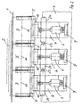
- the contact roller system is part of a winding machine for winding of moving webs 1, in particular paper webs or plastic films.
- the material webs 1 divided by longitudinal cuts are wound up into winding rolls 2, which are held in the winding machine with aligned sleeves; either the winding rolls 2 are wound on a common winding axis or each Winding roll 2 is held by two retractable clamping heads in its sleeve.
- Contact rollers are required especially at high winding speeds, to largely prevent air from entering the winding rollers 2.
- the contact roller system contains a row from side to side side by side arranged roller segments 3, whose axial length is less than that Minimum width of a winding roll to be wound 2. In the embodiment the length is 200 mm to 300 mm.
- Each roller segment 3 is one across the working width of the winding machine extending crossbar 4 individually Movable perpendicular to its axis of rotation 11 and thus against a winding roll 2 pressed on so that unavoidable differences in diameter of the winding rolls 2 can be compensated.
- each roller segment 3 on its end faces on two side bearing plates 5 free rotatably mounted, which extend parallel to the end face of the roller segment 3 and are attached to a carriage 6.
- the two bearing plates 5 of a roller segment 3 are each on the side facing away from the contact point to the winding roll 2 by means of a cross plate 25 connected to a rigid frame.
- Each carriage 6 is on the crossbar 4 in a linear guide 8, preferably a ball guide, to the winding roll 2 and back away from this, so perpendicular to the axis of rotation 11, slidably mounted.
- a pneumatic piston-cylinder unit 7 is used for the displacement movement on the one hand on a support plate 9 fastened on the crossbar 4, on the other hand the fork-shaped bearing part 10 of the carriage 6 is attached to which the cross plate 25 of the frame of a roller segment 3 is suspended.
- the sled 6 are designed narrower than a roller segment 3, so that a for each roller segment 3 Carriage 6 can be arranged on the crossbar 4.
- the side bearing plates 5 of two adjacent roller segments 3rd alternately arranged below or above the axis of rotation 11. This enables the two necessary bearing plates 5 between two roller segments 3 to be arranged one above the other perpendicular to the direction of displacement of the slide 6, as shown in Figure 1. There is the position of the side bearing plate 5 'of adjacent roller segment 3 'shown.
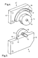
- FIGS. 4 and 5 The structure of a lateral bearing plate 5 is perspective in FIGS. 4 and 5 shown.
- the bearing plates 5 are preferably constructed identically so that they both for installation above the axis of rotation 11 ( Figure 4), as well as for the construction below the axis of rotation 11 (FIG. 5):
- Each bearing plate 5 consists of a plate-shaped part 12, in one of which Longitudinal edge a semi-circular cross-section 13 is incorporated for later mounting of the head of a fastening screw 22.
- On one side is on the part 12 a disc-shaped axle support 14 with a central through hole 15 attached, for example soldered flat, or with the plate-shaped part) 12 worked from a piece 5, 5 '.
- the central through hole 15 is aligned the groove 13.
- Concentric around the axle beam 14 is in the inside of part 12 Ring groove 16 incorporated, the curvature and extent is selected so that the appropriately designed end of a roller segment 3 without contact in the annular groove 16 can rotate.
- the back wall 17 of part 12 remaining at the bottom of the groove 16 is designed to be extremely thin as it has the minimum distance between two neighboring ones Roll segments 3 defines.
- the thickness of the back wall 17 is preferably 1 mm Or less. Despite the small thickness, the required strength has to be borne given a roller segment 3, since the part 12 is made thicker in the remaining area and the annular back wall 17 does not have a straight bending line.
- an appropriate Bevel of the parts 12 on the side facing a winding roll 2 can Wrap angle of the web 1 around a roller segment 3 regardless of the installation up or down and from the winding direction in the desired area can be set symmetrically for both possible winding directions.
- the Wrap angle of the web 1 on a roller segment 3 is 5 ° to 30 °, preferably between 8 ° and 20 °, in order to prevent the escape of those starting with the web 1 Favor air layer.
- each roller segment 3, 3 ' consists of a roller jacket 18, preferably made of metal, on which an outer running layer 19 made of rubber is applied.
- the roller shell 18 is on two lateral roller bearings 20 on one Axis 21 fastened freely rotatable. It is graded at each side end like this designed that the end of the contactless assembly in the annular groove 16 of the Bearing plate 5, 5 'immersed. The assembly takes place in such a way that the axial clearance between the end faces of a roller segment and the rear wall 17 in the Ring groove 16 is 0.2 mm to 5 mm, preferably about 0.3 mm.
- Each axis 21 is on both ends by means of a screw 22 on the disc-shaped Axle bracket 14 of the bearing plate 5, 5 'screwed.
- the screws 22 each extend from the outside centered on the axis of rotation 11 through the bore 15 of the axle support 14, with its head in the transverse groove 13 of the plate-shaped part 12 is partially sunk.
- the bearing plates 5, 5 'of two adjacent roller segments 3, 3 ' are alternately at the top or bottom of the fork-shaped bearing part 10 of the Carriage 6 attached. In Figure 3, the bearing plates 5 of the two outer Roller segments 3 arranged below, the bearing plates 5 'of the middle part above.
- the bearing plates 5 'of the middle roller segment 3 are for a clearer Represented drawn 180 ° around the axis of rotation 11 folded up. In the installed position are the back walls 17 of the bearing plates 5 'of the middle Roll segment 3 'exactly on the corresponding rear walls 17 of the bearing plates 5th the outer roller segments 3.
- the two the axes 21 of two adjacent Roller segments 3, 3 'bearing plates 5, 5' are thus in the space between the adjacent roller segments 3, 3 'one above the other and perpendicular to Axis of rotation 11 arranged displaceably against each other.
- the arrangement of the bearing plates 5, 5 'one above the other allows the required gap between two to keep adjacent roller segments 3, 3 'very low. To mark up To prevent sensitive webs 1, the gap is less than 5 mm, preferably it is between 0.8 mm and 3 mm.
- the coupled roller segments 3, 3 ' form a rigid in itself Pressure roller, which is pressed with the same pressure against a winding roller 2.
- the contact line of all roller segments 3, 3 'coupled together forms an exact one Just.
- a coupling of two adjacent roller segments 3, 3 ' is then advantageous if due to large thickness tolerances winding rollers 2 with zones of too strong differing winding reel diameters. Then it is undesirable that each roller segment 3, 3 'resting on the winding roll 2 adapts to the current diameter in its contact zone.
- a clutch two adjacent roller segments 3, 3 ' may be advantageous if one roller segment 3, 3 'with an excessive axial length over a winding roller 2.
- Switchable latches 23 are preferably used as coupling elements shown in Figures 1 and 2 - movable parallel to the axis of rotation 11 on the carriage 6th are attached.
- the bolts 23 are - for example by means of magnets or air cylinders - Movable back and forth along its axial direction in a guide 24 and move with their end into a corresponding opening in the guide 24 of the adjacent carriage 6.
- each winding roll 2 located roller segments 3 to a contact roller of the required axial Length interconnected without a shift of the roller segments 3 in axial direction or a replacement of contact rollers to the required Wrapping roll width is required. All roller segments 3 that are not required are pneumatically moved to an end position. With a format change without manual intervention correspondingly changed groups of roller segments 3 activated. If necessary, adjacent and active roller segments 3 by the switchable bolt 23 to a rigid contact roller with an exactly straight Contact line coupled together. The contact rollers interconnected in this way are pressed against the winding rollers 2 under an adjustable pressure in order to To largely prevent air from entering the winding rollers 2.
Landscapes
- Winding Of Webs (AREA)
- Replacement Of Web Rolls (AREA)
Description
- Figur 1
- Die Seitenansicht eines Kontaktwalzensystems nach der Erfindung,
- Figur 2
- eine Draufsicht auf das Kontaktwalzensystem nach Figur 1,
- Figur 3
- ausschnittsweise einen Querschnitt und die
- Figuren 4 und 5
- in perspektivischer Darstellung die seitlichen Lagerplatten eines Walzensegments.
Claims (9)
- Kontaktwalzensystem einer Wickelmaschine mit mehreren Stirnseite an Stirnseite nebeneinander frei drehbar gelagerten Walzensegmenten (3, 3'), dadurch gekennzeichnet, daß die Walzensegmente (3, 3') von einem Rahmen (25) gehalten werden, der zwischen den Walzensegmenten (3, 3') angeordnete und sich parallel zu deren Stirnseiten erstreckende Lagerplatten (5, 5') enthält, wobei in die Innenseite jeder Lagerplatte (5, 5') eine Ringnut (16) eingearbeitet ist, in der das Ende eines Walzensegments (3, 3') berührungslos rotieren kann.
- Kontaktwalzensystem, nach Anspruch 1, dadurch gekennzeichnet, daß jedes Walzensegment (3, 3') von einem Rahmen gehalten wird, der senkrecht zur Drehachse (11) des Walzensegments (3, 3') bewegbar gelagert ist und daß jeder Rahmen eines Walzensegments (3, 3') zwei sich parallel zu dessen Stirnseiten erstreckende seitliche Lagerplatten (5, 5') enthält, wobei die benachbarten Lagerplatten (5, 5') zweier Walzensegmente (3, 3') senkrecht zur Bewegungsrichtung übereinander angeordnet sind.
- Walzensystem nach Anspruch 1 oder 2, dadurch gekennzeichnet, daß der Spalt zwischen benachbarten Walzensegmenten (3, 3') kleiner als 5 mm ist, bevorzugt zwischen 0,8 mm und 3 mm beträgt.
- Walzensystem nach einem der Ansprüche 1 bis 3, dadurch gekennzeichnet, daß jedes Walzensegment (3, 3') mittels eines eigenen Antriebs (7) senkrecht zu seiner Drehachse (11) verschiebbar an einer gemeinsamen Quertraverse (4) gelagert ist.
- Walzensystem nach einem der Ansprüche 1 bis 4, dadurch gekennzeichnet, daß benachbarte Walzensegmente (3, 3') mechanisch aneinander kuppelbar sind, um eine in sich starre Andruckwalze zu bilden.
- Walzensystem nach einem der Ansprüche 1 bis 6, dadurch gekennzeichnet, daß der axiale Freiraum zwischen der Stirnfläche eines Walzensegments (3, 3') und der Rückenwand (17) der Ringnut (16) 0,2 mm bis 5 mm, bevorzugt 0,3 mm, beträgt.
- Walzensystem nach einem der Ansprüche 4 bis 6, dadurch gekennzeichnet, daß die Quertraverse (4) mit den daran gelagerten Walzensegmenten (3) in eine Changierbewegung parallel zur Drehachse (11) der Walzensegmente (3) versetzbar ist.
- Wickelmaschine zum Aufwickeln einer laufenden Warenbahn, insbeosndere einer Papierbahn oder Kunststoffolie, dadurch gekennzeichnet, daß sie ein Kontaktwalzensystem, gemäß einem der Ansprüche 1 bis 7 aufweist.
- Wickelmaschine nach Anspruch 8, dadurch gekennzeichnet, daß ein Kontakwalzensystem so angeordnet ist, daß die einer Wickelrolle (2) zulaufende Bahn (1) ein Walzensegment (3) in einem Winkel von 5° bis 30°, bevorzugt zwischen 8° und 20°, umschlingt.
Applications Claiming Priority (3)
| Application Number | Priority Date | Filing Date | Title |
|---|---|---|---|
| DE19805412 | 1998-02-11 | ||
| DE19805412A DE19805412A1 (de) | 1998-02-11 | 1998-02-11 | Kontaktwalzensystem einer Wickelmaschine |
| PCT/EP1999/000559 WO1999041174A1 (de) | 1998-02-11 | 1999-01-28 | Kontaktwalzensystem einer wickelmaschine |
Publications (2)
| Publication Number | Publication Date |
|---|---|
| EP0986509A1 EP0986509A1 (de) | 2000-03-22 |
| EP0986509B1 true EP0986509B1 (de) | 2003-04-23 |
Family
ID=7857289
Family Applications (1)
| Application Number | Title | Priority Date | Filing Date |
|---|---|---|---|
| EP99904824A Expired - Lifetime EP0986509B1 (de) | 1998-02-11 | 1999-01-28 | Kontaktwalzensystem einer wickelmaschine |
Country Status (6)
| Country | Link |
|---|---|
| US (1) | US6182919B1 (de) |
| EP (1) | EP0986509B1 (de) |
| JP (1) | JP2001524917A (de) |
| DE (2) | DE19805412A1 (de) |
| ES (1) | ES2196768T3 (de) |
| WO (1) | WO1999041174A1 (de) |
Families Citing this family (9)
| Publication number | Priority date | Publication date | Assignee | Title |
|---|---|---|---|---|
| DE19848532A1 (de) | 1998-10-21 | 2000-04-27 | Kampf Gmbh & Co Maschf | Kontaktwalzensystem einer Wickelmaschine |
| DE19939506A1 (de) | 1999-08-20 | 2001-02-22 | Voith Paper Patent Gmbh | Verfahren und Wickelmaschine zum Aufwickeln einer Materialbahn |
| DE19940665A1 (de) * | 1999-08-27 | 2001-04-05 | Voith Paper Patent Gmbh | Rollenwickeleinrichtung und Aufwickelverfahren |
| US20020017122A1 (en) * | 2000-04-01 | 2002-02-14 | Mccabe Troy A. | Wire containment apparatus for wire drawing machines |
| DE10131364A1 (de) * | 2001-06-28 | 2003-01-16 | Wt Wickeltechnik Gmbh | Kontaktwalzensystem einer Wickelmaschine für dünnes Bandmaterial |
| DE10202020A1 (de) * | 2002-01-18 | 2003-07-24 | Kampf Gmbh & Co Maschf | Walzensystem, insbesondere Kontaktwalzensystem einer Wickelmaschine |
| DE10250863B4 (de) * | 2002-10-31 | 2005-06-02 | Brückner Maschinenbau GmbH | Wickelvorrichtung für bahnförmige Materialien, insbesondere Kunststofffolien |
| DE50303106D1 (de) * | 2003-02-12 | 2006-06-01 | Maschb Wilhelm Kochsiek Gmbh | Aufwickler |
| DE102013200066A1 (de) * | 2013-01-04 | 2014-07-10 | Achenbach Buschhütten GmbH & Co. KG | Wickelstation und Verfahren zu deren Betrieb |
Family Cites Families (15)
| Publication number | Priority date | Publication date | Assignee | Title |
|---|---|---|---|---|
| FI45589C (fi) * | 1969-04-29 | 1972-07-10 | Ahlstroem Oy | Liikkuva telayhdistelmä |
| DE2139159C3 (de) * | 1971-08-05 | 1974-08-15 | Jagenberg-Werke Ag, 4000 Duesseldorf | Vorrichtung zum Breitstrecken von Warenbahnen, insbesondere von Papierbahnen |
| US3854646A (en) * | 1973-07-10 | 1974-12-17 | Ahlstroem Dev Gmbh | Pressure-balanced wide web guide roller |
| JPS5213064A (en) * | 1975-07-21 | 1977-02-01 | Nishimura Seisakusho:Kk | Each independent taking-up motion in a slitter |
| FI53561C (fi) * | 1976-03-12 | 1978-06-12 | Ahlstroem Oy | Belastningsvals i rullmaskin |
| US4472155A (en) * | 1983-05-10 | 1984-09-18 | Valmet-Dominion Inc. | Divided roll mounting |
| FI69440C (fi) * | 1983-07-22 | 1986-02-10 | Waertsilae Oy Ab | Anordning foer utbredning av bana |
| JPS60148861A (ja) * | 1984-01-10 | 1985-08-06 | Baimotetsuku:Kk | 多条帯板の定張力巻取装置 |
| DE3900960C2 (de) * | 1989-01-14 | 1994-02-24 | Sundwiger Eisen Maschinen | Vorrichtung zum Längsteilen eines Bandes und Aufwickeln der Streifen des geteilten Bandes |
| DE3941384C1 (de) * | 1989-12-15 | 1991-06-27 | Kampf Gmbh & Co Maschinenfabrik, 5276 Wiehl, De | |
| DE9201791U1 (de) * | 1991-12-13 | 1992-04-09 | J.M. Voith Gmbh, 7920 Heidenheim | Wickelmaschine zum Aufwickeln einer Bahn, insbesondere einer Papierbahn |
| DE19607349A1 (de) * | 1996-02-27 | 1997-08-28 | Voith Sulzer Papiermasch Gmbh | Verfahren und Vorrichtung zum Aufwickeln einer Papierbahn zu einer Rolle |
| DE19651483A1 (de) * | 1996-04-19 | 1997-10-23 | Jagenberg Papiertech Gmbh | Druckrollensystem für eine Wickelmaschine |
| FI99278C (fi) * | 1996-06-10 | 1998-04-27 | Valmet Corp | Säätömenetelmä rullauksessa |
| FI105464B (fi) * | 1996-06-10 | 2000-08-31 | Valmet Corp | Menetelmä ja laite rullauksessa |
-
1998
- 1998-02-11 DE DE19805412A patent/DE19805412A1/de not_active Withdrawn
-
1999
- 1999-01-28 WO PCT/EP1999/000559 patent/WO1999041174A1/de not_active Ceased
- 1999-01-28 JP JP54096599A patent/JP2001524917A/ja active Pending
- 1999-01-28 ES ES99904824T patent/ES2196768T3/es not_active Expired - Lifetime
- 1999-01-28 DE DE59905156T patent/DE59905156D1/de not_active Expired - Lifetime
- 1999-01-28 US US09/381,532 patent/US6182919B1/en not_active Expired - Fee Related
- 1999-01-28 EP EP99904824A patent/EP0986509B1/de not_active Expired - Lifetime
Also Published As
| Publication number | Publication date |
|---|---|
| US6182919B1 (en) | 2001-02-06 |
| EP0986509A1 (de) | 2000-03-22 |
| DE19805412A1 (de) | 1999-08-12 |
| ES2196768T3 (es) | 2003-12-16 |
| DE59905156D1 (de) | 2003-05-28 |
| JP2001524917A (ja) | 2001-12-04 |
| WO1999041174A1 (de) | 1999-08-19 |
Similar Documents
| Publication | Publication Date | Title |
|---|---|---|
| DE3924053C2 (de) | ||
| EP0453869B1 (de) | Wendestangenanordnung zum Übereinanderführen von Strängen | |
| EP1265804B1 (de) | Einrichtung zum umlenken einer materialbahn | |
| DE3941384C1 (de) | ||
| DE2812958C2 (de) | ||
| DE4344920A1 (de) | Vorrichtung zum transversalen Schneiden von verschiedenartigen Materialien | |
| AT401922B (de) | Wickelmaschine für bahnförmiges gut, insbesondere papier | |
| DE4128970A1 (de) | Abschervorrichtung | |
| DE2222608C2 (de) | Ringwalzwerk | |
| EP0986509B1 (de) | Kontaktwalzensystem einer wickelmaschine | |
| DE2514876B1 (de) | Rollenschneid- und wickelmaschine | |
| EP1065031A2 (de) | Vorrichtung zum Querperforieren von Bahnen | |
| DE1574418B1 (de) | Fuehrungsvorrichtung fuer laufende Materialbahnen | |
| DE2612375C2 (de) | Spannkopf für die die Kernrohre von Wickeln aus Papier, Kunststoffolien oder dergleichen | |
| EP0439830A2 (de) | Vorrichtung zur Be- oder Verarbeitung einer Materialbahn | |
| EP1123247B1 (de) | Kontaktwalzensystem einer wickelmaschine | |
| DE2342515B1 (de) | Rollenwickelmaschine | |
| DE102005010948B4 (de) | Vorrichtung zum Trennen einer bedruckten Papierbahn | |
| DE2905631C2 (de) | Walzgerüst mit mindestens einer von einer losen drehbaren Hülse umgebenden Stützwalze | |
| EP0933320B1 (de) | Rollenwickler | |
| EP1270469B1 (de) | Kontaktwalzensystem einer Wickelmaschine für dünnes Bandmaterial | |
| DE60118964T2 (de) | Vorrichtung und verfahren zum wickeln von bahnen | |
| DE102008043310A1 (de) | Breitstreckeinrichtung | |
| DE102011116308A1 (de) | Doppeltragwalzenroller | |
| DE1921344A1 (de) | Kerneinspannvorrichtung |
Legal Events
| Date | Code | Title | Description |
|---|---|---|---|
| PUAI | Public reference made under article 153(3) epc to a published international application that has entered the european phase |
Free format text: ORIGINAL CODE: 0009012 |
|
| 17P | Request for examination filed |
Effective date: 19990727 |
|
| AK | Designated contracting states |
Kind code of ref document: A1 Designated state(s): DE ES FR GB IT |
|
| 17Q | First examination report despatched |
Effective date: 20011107 |
|
| GRAH | Despatch of communication of intention to grant a patent |
Free format text: ORIGINAL CODE: EPIDOS IGRA |
|
| GRAH | Despatch of communication of intention to grant a patent |
Free format text: ORIGINAL CODE: EPIDOS IGRA |
|
| GRAA | (expected) grant |
Free format text: ORIGINAL CODE: 0009210 |
|
| AK | Designated contracting states |
Designated state(s): DE ES FR GB IT |
|
| REG | Reference to a national code |
Ref country code: GB Ref legal event code: FG4D Free format text: NOT ENGLISH |
|
| GBT | Gb: translation of ep patent filed (gb section 77(6)(a)/1977) |
Effective date: 20030423 |
|
| REF | Corresponds to: |
Ref document number: 59905156 Country of ref document: DE Date of ref document: 20030528 Kind code of ref document: P |
|
| REG | Reference to a national code |
Ref country code: ES Ref legal event code: FG2A Ref document number: 2196768 Country of ref document: ES Kind code of ref document: T3 |
|
| ET | Fr: translation filed | ||
| PLBE | No opposition filed within time limit |
Free format text: ORIGINAL CODE: 0009261 |
|
| STAA | Information on the status of an ep patent application or granted ep patent |
Free format text: STATUS: NO OPPOSITION FILED WITHIN TIME LIMIT |
|
| 26N | No opposition filed |
Effective date: 20040126 |
|
| PGFP | Annual fee paid to national office [announced via postgrant information from national office to epo] |
Ref country code: ES Payment date: 20080130 Year of fee payment: 10 |
|
| PGFP | Annual fee paid to national office [announced via postgrant information from national office to epo] |
Ref country code: IT Payment date: 20080123 Year of fee payment: 10 |
|
| PGFP | Annual fee paid to national office [announced via postgrant information from national office to epo] |
Ref country code: FR Payment date: 20080111 Year of fee payment: 10 |
|
| REG | Reference to a national code |
Ref country code: FR Ref legal event code: ST Effective date: 20091030 |
|
| REG | Reference to a national code |
Ref country code: ES Ref legal event code: FD2A Effective date: 20090129 |
|
| PG25 | Lapsed in a contracting state [announced via postgrant information from national office to epo] |
Ref country code: FR Free format text: LAPSE BECAUSE OF NON-PAYMENT OF DUE FEES Effective date: 20090202 Ref country code: ES Free format text: LAPSE BECAUSE OF NON-PAYMENT OF DUE FEES Effective date: 20090129 |
|
| PG25 | Lapsed in a contracting state [announced via postgrant information from national office to epo] |
Ref country code: IT Free format text: LAPSE BECAUSE OF NON-PAYMENT OF DUE FEES Effective date: 20090128 |
|
| PGFP | Annual fee paid to national office [announced via postgrant information from national office to epo] |
Ref country code: DE Payment date: 20170120 Year of fee payment: 19 |
|
| PGFP | Annual fee paid to national office [announced via postgrant information from national office to epo] |
Ref country code: GB Payment date: 20170119 Year of fee payment: 19 |
|
| REG | Reference to a national code |
Ref country code: DE Ref legal event code: R119 Ref document number: 59905156 Country of ref document: DE |
|
| GBPC | Gb: european patent ceased through non-payment of renewal fee |
Effective date: 20180128 |
|
| PG25 | Lapsed in a contracting state [announced via postgrant information from national office to epo] |
Ref country code: DE Free format text: LAPSE BECAUSE OF NON-PAYMENT OF DUE FEES Effective date: 20180801 |
|
| PG25 | Lapsed in a contracting state [announced via postgrant information from national office to epo] |
Ref country code: GB Free format text: LAPSE BECAUSE OF NON-PAYMENT OF DUE FEES Effective date: 20180128 |