EP0986509B1 - Contact roller system of a winding machine - Google Patents
Contact roller system of a winding machine Download PDFInfo
- Publication number
- EP0986509B1 EP0986509B1 EP99904824A EP99904824A EP0986509B1 EP 0986509 B1 EP0986509 B1 EP 0986509B1 EP 99904824 A EP99904824 A EP 99904824A EP 99904824 A EP99904824 A EP 99904824A EP 0986509 B1 EP0986509 B1 EP 0986509B1
- Authority
- EP
- European Patent Office
- Prior art keywords
- roll
- segments
- segment
- contact
- winding
- Prior art date
- Legal status (The legal status is an assumption and is not a legal conclusion. Google has not performed a legal analysis and makes no representation as to the accuracy of the status listed.)
- Expired - Lifetime
Links
Images


Classifications
-
- B—PERFORMING OPERATIONS; TRANSPORTING
- B65—CONVEYING; PACKING; STORING; HANDLING THIN OR FILAMENTARY MATERIAL
- B65H—HANDLING THIN OR FILAMENTARY MATERIAL, e.g. SHEETS, WEBS, CABLES
- B65H18/00—Winding webs
- B65H18/08—Web-winding mechanisms
- B65H18/26—Mechanisms for controlling contact pressure on winding-web package, e.g. for regulating the quantity of air between web layers
-
- B—PERFORMING OPERATIONS; TRANSPORTING
- B65—CONVEYING; PACKING; STORING; HANDLING THIN OR FILAMENTARY MATERIAL
- B65H—HANDLING THIN OR FILAMENTARY MATERIAL, e.g. SHEETS, WEBS, CABLES
- B65H2301/00—Handling processes for sheets or webs
- B65H2301/40—Type of handling process
- B65H2301/41—Winding, unwinding
- B65H2301/414—Winding
- B65H2301/4143—Performing winding process
- B65H2301/41432—Performing winding process special features of winding process
- B65H2301/414322—Performing winding process special features of winding process oscillated winding, i.e. oscillating the axis of the winding roller or material
-
- B—PERFORMING OPERATIONS; TRANSPORTING
- B65—CONVEYING; PACKING; STORING; HANDLING THIN OR FILAMENTARY MATERIAL
- B65H—HANDLING THIN OR FILAMENTARY MATERIAL, e.g. SHEETS, WEBS, CABLES
- B65H2301/00—Handling processes for sheets or webs
- B65H2301/40—Type of handling process
- B65H2301/41—Winding, unwinding
- B65H2301/414—Winding
- B65H2301/4148—Winding slitting
-
- B—PERFORMING OPERATIONS; TRANSPORTING
- B65—CONVEYING; PACKING; STORING; HANDLING THIN OR FILAMENTARY MATERIAL
- B65H—HANDLING THIN OR FILAMENTARY MATERIAL, e.g. SHEETS, WEBS, CABLES
- B65H2404/00—Parts for transporting or guiding the handled material
- B65H2404/10—Rollers
- B65H2404/13—Details of longitudinal profile
- B65H2404/132—Details of longitudinal profile arrangement of segments along axis
- B65H2404/1321—Segments juxtaposed along axis
-
- B—PERFORMING OPERATIONS; TRANSPORTING
- B65—CONVEYING; PACKING; STORING; HANDLING THIN OR FILAMENTARY MATERIAL
- B65H—HANDLING THIN OR FILAMENTARY MATERIAL, e.g. SHEETS, WEBS, CABLES
- B65H2404/00—Parts for transporting or guiding the handled material
- B65H2404/40—Shafts, cylinders, drums, spindles
- B65H2404/43—Rider roll construction
- B65H2404/431—Rider roll construction involving several segments in axial direction
-
- B—PERFORMING OPERATIONS; TRANSPORTING
- B65—CONVEYING; PACKING; STORING; HANDLING THIN OR FILAMENTARY MATERIAL
- B65H—HANDLING THIN OR FILAMENTARY MATERIAL, e.g. SHEETS, WEBS, CABLES
- B65H2601/00—Problem to be solved or advantage achieved
- B65H2601/20—Avoiding or preventing undesirable effects
- B65H2601/21—Dynamic air effects
- B65H2601/211—Entrapping air in or under the material
Definitions
- the invention relates to a contact roller system of a winding machine with several Face to face side by side freely rotatable roller segments and a winding machine for winding a running web, in particular one Paper web or plastic film that contains the contact roller system.
- winding machine can be divided with the winding machine by longitudinal cuts Winding reels wound up, which are held while winding with aligned sleeves then the contact rollers for each winding roll must be individually movable, to compensate for unavoidable differences in diameter of the winding rolls.
- the axial length of a contact roller must be equal to or greater than the width of the Winding roll against which it is pressed.
- the invention has for its object a generic contact roller system to improve so that the gap between two adjacent roller segments for Avoidance of markings can be kept as low as possible.
- each roller segment is in its position and its contact pressure individually adjustable.
- Narrow roller segments can be used arrange so close to each other with individual pressure mechanism and control that they share the function of a contact roller with one of the winding roll width appropriate length.
- the Computer-controlled contact rollers automatically change the width of the winding rolls be adjusted.
- the gap between two adjacent roller segments can be due to the arrangement of the bearing plates keep one another extremely low to avoid ring marks when winding to avoid the winding rolls.
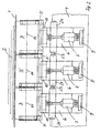
- the contact roller system is part of a winding machine for winding of moving webs 1, in particular paper webs or plastic films.
- the material webs 1 divided by longitudinal cuts are wound up into winding rolls 2, which are held in the winding machine with aligned sleeves; either the winding rolls 2 are wound on a common winding axis or each Winding roll 2 is held by two retractable clamping heads in its sleeve.
- Contact rollers are required especially at high winding speeds, to largely prevent air from entering the winding rollers 2.
- the contact roller system contains a row from side to side side by side arranged roller segments 3, whose axial length is less than that Minimum width of a winding roll to be wound 2. In the embodiment the length is 200 mm to 300 mm.
- Each roller segment 3 is one across the working width of the winding machine extending crossbar 4 individually Movable perpendicular to its axis of rotation 11 and thus against a winding roll 2 pressed on so that unavoidable differences in diameter of the winding rolls 2 can be compensated.
- each roller segment 3 on its end faces on two side bearing plates 5 free rotatably mounted, which extend parallel to the end face of the roller segment 3 and are attached to a carriage 6.
- the two bearing plates 5 of a roller segment 3 are each on the side facing away from the contact point to the winding roll 2 by means of a cross plate 25 connected to a rigid frame.
- Each carriage 6 is on the crossbar 4 in a linear guide 8, preferably a ball guide, to the winding roll 2 and back away from this, so perpendicular to the axis of rotation 11, slidably mounted.
- a pneumatic piston-cylinder unit 7 is used for the displacement movement on the one hand on a support plate 9 fastened on the crossbar 4, on the other hand the fork-shaped bearing part 10 of the carriage 6 is attached to which the cross plate 25 of the frame of a roller segment 3 is suspended.
- the sled 6 are designed narrower than a roller segment 3, so that a for each roller segment 3 Carriage 6 can be arranged on the crossbar 4.
- the side bearing plates 5 of two adjacent roller segments 3rd alternately arranged below or above the axis of rotation 11. This enables the two necessary bearing plates 5 between two roller segments 3 to be arranged one above the other perpendicular to the direction of displacement of the slide 6, as shown in Figure 1. There is the position of the side bearing plate 5 'of adjacent roller segment 3 'shown.
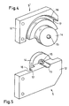
- FIGS. 4 and 5 The structure of a lateral bearing plate 5 is perspective in FIGS. 4 and 5 shown.
- the bearing plates 5 are preferably constructed identically so that they both for installation above the axis of rotation 11 ( Figure 4), as well as for the construction below the axis of rotation 11 (FIG. 5):
- Each bearing plate 5 consists of a plate-shaped part 12, in one of which Longitudinal edge a semi-circular cross-section 13 is incorporated for later mounting of the head of a fastening screw 22.
- On one side is on the part 12 a disc-shaped axle support 14 with a central through hole 15 attached, for example soldered flat, or with the plate-shaped part) 12 worked from a piece 5, 5 '.
- the central through hole 15 is aligned the groove 13.
- Concentric around the axle beam 14 is in the inside of part 12 Ring groove 16 incorporated, the curvature and extent is selected so that the appropriately designed end of a roller segment 3 without contact in the annular groove 16 can rotate.
- the back wall 17 of part 12 remaining at the bottom of the groove 16 is designed to be extremely thin as it has the minimum distance between two neighboring ones Roll segments 3 defines.
- the thickness of the back wall 17 is preferably 1 mm Or less. Despite the small thickness, the required strength has to be borne given a roller segment 3, since the part 12 is made thicker in the remaining area and the annular back wall 17 does not have a straight bending line.
- an appropriate Bevel of the parts 12 on the side facing a winding roll 2 can Wrap angle of the web 1 around a roller segment 3 regardless of the installation up or down and from the winding direction in the desired area can be set symmetrically for both possible winding directions.
- the Wrap angle of the web 1 on a roller segment 3 is 5 ° to 30 °, preferably between 8 ° and 20 °, in order to prevent the escape of those starting with the web 1 Favor air layer.
- each roller segment 3, 3 ' consists of a roller jacket 18, preferably made of metal, on which an outer running layer 19 made of rubber is applied.
- the roller shell 18 is on two lateral roller bearings 20 on one Axis 21 fastened freely rotatable. It is graded at each side end like this designed that the end of the contactless assembly in the annular groove 16 of the Bearing plate 5, 5 'immersed. The assembly takes place in such a way that the axial clearance between the end faces of a roller segment and the rear wall 17 in the Ring groove 16 is 0.2 mm to 5 mm, preferably about 0.3 mm.
- Each axis 21 is on both ends by means of a screw 22 on the disc-shaped Axle bracket 14 of the bearing plate 5, 5 'screwed.
- the screws 22 each extend from the outside centered on the axis of rotation 11 through the bore 15 of the axle support 14, with its head in the transverse groove 13 of the plate-shaped part 12 is partially sunk.
- the bearing plates 5, 5 'of two adjacent roller segments 3, 3 ' are alternately at the top or bottom of the fork-shaped bearing part 10 of the Carriage 6 attached. In Figure 3, the bearing plates 5 of the two outer Roller segments 3 arranged below, the bearing plates 5 'of the middle part above.
- the bearing plates 5 'of the middle roller segment 3 are for a clearer Represented drawn 180 ° around the axis of rotation 11 folded up. In the installed position are the back walls 17 of the bearing plates 5 'of the middle Roll segment 3 'exactly on the corresponding rear walls 17 of the bearing plates 5th the outer roller segments 3.
- the two the axes 21 of two adjacent Roller segments 3, 3 'bearing plates 5, 5' are thus in the space between the adjacent roller segments 3, 3 'one above the other and perpendicular to Axis of rotation 11 arranged displaceably against each other.
- the arrangement of the bearing plates 5, 5 'one above the other allows the required gap between two to keep adjacent roller segments 3, 3 'very low. To mark up To prevent sensitive webs 1, the gap is less than 5 mm, preferably it is between 0.8 mm and 3 mm.
- the coupled roller segments 3, 3 ' form a rigid in itself Pressure roller, which is pressed with the same pressure against a winding roller 2.
- the contact line of all roller segments 3, 3 'coupled together forms an exact one Just.
- a coupling of two adjacent roller segments 3, 3 ' is then advantageous if due to large thickness tolerances winding rollers 2 with zones of too strong differing winding reel diameters. Then it is undesirable that each roller segment 3, 3 'resting on the winding roll 2 adapts to the current diameter in its contact zone.
- a clutch two adjacent roller segments 3, 3 ' may be advantageous if one roller segment 3, 3 'with an excessive axial length over a winding roller 2.
- Switchable latches 23 are preferably used as coupling elements shown in Figures 1 and 2 - movable parallel to the axis of rotation 11 on the carriage 6th are attached.
- the bolts 23 are - for example by means of magnets or air cylinders - Movable back and forth along its axial direction in a guide 24 and move with their end into a corresponding opening in the guide 24 of the adjacent carriage 6.
- each winding roll 2 located roller segments 3 to a contact roller of the required axial Length interconnected without a shift of the roller segments 3 in axial direction or a replacement of contact rollers to the required Wrapping roll width is required. All roller segments 3 that are not required are pneumatically moved to an end position. With a format change without manual intervention correspondingly changed groups of roller segments 3 activated. If necessary, adjacent and active roller segments 3 by the switchable bolt 23 to a rigid contact roller with an exactly straight Contact line coupled together. The contact rollers interconnected in this way are pressed against the winding rollers 2 under an adjustable pressure in order to To largely prevent air from entering the winding rollers 2.
Landscapes
- Winding Of Webs (AREA)
- Replacement Of Web Rolls (AREA)
Description
Die Erfindung betrifft ein Kontaktwalzensystem einer Wickelmaschine mit mehreren, Stirnseite an Stirnseite nebeneinander frei drehbar gelagerten Walzensegmenten und eine Wickelmaschine zum Aufwickeln einer laufenden Warenbahn, insbesondere einer Papierbahn oder Kunststoffolie, die das Kontaktwalzensystem enthält.The invention relates to a contact roller system of a winding machine with several Face to face side by side freely rotatable roller segments and a winding machine for winding a running web, in particular one Paper web or plastic film that contains the contact roller system.
In Wickelmaschinen zum Aufwickeln von laufenden Warenbahnen, beispielsweise Papierbahnen oder Kunststoffolien, werden bekannterweise Kontaktwalzen als Andruck- oder Abquetschwalzen verwendet, um insbesondere bei hohen Wickelgeschwindigkelten das Eindringen von Luft in die Wickelrollen weitgehend zu verhindern.In winding machines for winding up running webs, for example Paper webs or plastic films are known to be contact rollers Pinch or squeeze rollers are used, especially at high winding speeds largely prevent air from entering the winding rolls.
Werden mit der Wickelmaschine durch Längsschnitte unterteilten Warenbahnen zu Wickelrollen aufgewickelt, die beim Aufwickeln mit fluchtenden Hülsen gehalten werden, dann müssen die Kontaktwalzen für jede Wickelrolle einzeln beweglich sein, um unvermeidbare Durchmesserunterschiede der Wickelrollen auszugleichen. Die axiale Länge einer Kontaktwalze muß dabei gleich oder größer sein als die Breite der Wickelrolle, gegen die sie angedrückt wird.Can be divided with the winding machine by longitudinal cuts Winding reels wound up, which are held while winding with aligned sleeves then the contact rollers for each winding roll must be individually movable, to compensate for unavoidable differences in diameter of the winding rolls. The axial length of a contact roller must be equal to or greater than the width of the Winding roll against which it is pressed.
Es ist bekannt, Kontaktwalzen mit fester Länge in einzeln beweglichen Lagern aufzuhängen und pneumatisch gegen die jeweilige Wickelrolle anzudrücken. Kontaktwalzen mit fester Länge können nur einen begrenzten Breitenbereich von Wickelrollen abdecken. Bei einem Wechsel der Wickelbreiten außerhalb dieses Bereichs müssen die Kontaktwalzen gegen andere mit passender Länge ausgewechselt werden. Es müssen auch die Lagerstellen seitlich verschoben und ungefähr mittensymmetrisch zur Breite der jeweiligen Wickelrolle positioniert werden. Zum Betreiben einer Wickelmaschine mit sehr variablen Schnittbreiten sind demnach eine Vielzahl von bereit stehenden Kontaktwalzen erforderlich. Zudem müssen bei jedem Formatwechsel die Kontaktwalzen gewechselt und neu positioniert werden.It is known to have fixed length contact rollers in individually movable bearings hang up and press pneumatically against the respective winding roll. Fixed length contact rollers can only have a limited width range of Cover winding rolls. When changing the winding widths outside of this Area, the contact rollers must be replaced with others of suitable length become. The bearings must also be moved laterally and approximately be positioned symmetrically to the width of the respective winding roll. To the Operating a winding machine with very variable cutting widths is therefore one A large number of contact rollers are required. In addition, with everyone Format change the contact rollers are changed and repositioned.
Aus der DE-PS 39 41 384 ist eine Wickelmaschine mit einem gattungsgemäßen Kontaktwalzensystem bekannt, bei der Walzensegmente als Andruckwalzen lückenlos nebeneinander auf einer Tragachse exzentrisch gelagert sind. Die exzentrische Lagerung bewirkt, daß sich jedes Walzensegment beim gemeinsamen Andrücken gegen die Wickelrollen senkrecht zu seiner Drehachse relativ zu dem benachbarten Walzensegment bewegen kann. Weiterhin können durch eine Verriegelung der Walzensegmente gegeneinander Gruppen auf der Tragachse gebildet werden. Die einzelnen Walzensegmente können zwar ihre Position relativ zu der Wickelrolle anpassen, es ist jedoch nicht möglich, jedes einzelne Walzensegment mit einer individuell einstellbaren Anpreßkraft gegen die Wickelrolle zu drücken. Für sehr breite Maschinen ist diese Lösung unbrauchbar, da die tragende Achse im Inneren der Walzensegmente liegt und im Durchmesser begrenzt ist.From DE-PS 39 41 384 is a winding machine with a generic Contact roller system known, in the roller segments as pressure rollers without gaps are mounted eccentrically next to each other on a support axis. The eccentric Storage causes each roller segment to press together against the winding rolls perpendicular to its axis of rotation relative to the neighboring one Can move roller segment. Furthermore, by locking the Roll segments against each other groups are formed on the support axis. The individual roller segments can change their position relative to the winding roll adjust, but it is not possible to use every single roller segment to press the individually adjustable contact pressure against the winding roll. For very wide ones This solution is unusable because the load-bearing axis is inside the machine Roller segments lies and is limited in diameter.
Der Erfindung liegt die Aufgabe zugrunde, ein gattungsgemäßes Kontaktwalzensystem so zu verbessern, daß der Spalt zwischen zwei benachbarten Walzensegmenten zur Vermeidung von Markierungen möglichst gering gehalten werden kann.The invention has for its object a generic contact roller system to improve so that the gap between two adjacent roller segments for Avoidance of markings can be kept as low as possible.
Diese Aufgabe wird mit den Merkmalen des Patentanspruchs 1 gelöst.This object is achieved with the features of patent claim 1.
Bei der Lösung nach Patentanspruch 2 ist jedes Walzensegment in seiner Position
und seiner Anpreßkraft individuell einstellbar. Es lassen sich schmale Walzensegmente
mit individueller Andruckmechanik so dicht nebeneinander anordnen und
steuern, daß sie gemeinsam die Funktion einer Kontaktwalze mit einer der Wickelrollenbreite
entsprechenden Länge übernehmen. Bei einem Formatwechsel können die
Kontaktwalzen computergesteuert automatisch einer geänderten Wickelrolienbreite
angepaßt werden. Der Spalt zwischen zwei benachbarten Walzensegmenten läßt sich
aufgrund der Anordnung der Lagerplatten
übereinander extrem gering halten, um beim Aufwickeln ringförmige Markierungen au
den Wickelrollen zu vermeiden.In the solution according to
Die Unteransprüche enthalten bevorzugte, da besonders vorteilhafte Ausgestaltungen der Erfindung.The subclaims contain preferred, since particularly advantageous, configurations the invention.
Die Zeichnungen dienen zur Erläuterung der Erfindung anhand eines vereinfacht dargestellten Ausführungsbeispiels.The drawings serve to explain the invention with reference to a simplified illustrated embodiment.
Es zeigen:
- Figur 1
- Die Seitenansicht eines Kontaktwalzensystems nach der Erfindung,
Figur 2- eine Draufsicht auf das Kontaktwalzensystem nach Figur 1,
Figur 3- ausschnittsweise einen Querschnitt und die
Figuren 4 und 5- in perspektivischer Darstellung die seitlichen Lagerplatten eines Walzensegments.
- Figure 1
- The side view of a contact roller system according to the invention,
- Figure 2
- 2 shows a top view of the contact roller system according to FIG. 1,
- Figure 3
- sections of a cross section and
- Figures 4 and 5
- in perspective the side bearing plates of a roller segment.
Das Kontaktwalzensystem ist ein Bestandteil einer Wickelmaschine zum Aufwickeln
von laufenden Warenbahnen 1, insbesondere Papierbahnen oder Kunststoffolien. Die
durch Längsschnitte unterteilten Warenbahnen 1 werden zu Wickelrollen 2 aufgewikkelt,
die in der Wickelmaschine mit fluchtenden Hülsen gehalten werden; entweder
werden die Wickelrollen 2 auf einer gemeinsamen Wickelachse aufgewickelt oder jede
Wickelrolle 2 wird von zwei in ihre Hülse einfahrbaren Spannköpfen gehalten.
Insbesondere bei hohen Aufwickelgeschwindigkeiten sind Kontaktwalzen erforderlich,
um das Eindringen von Luft in die Wickelrollen 2 weitgehend zu verhindern. The contact roller system is part of a winding machine for winding
of moving webs 1, in particular paper webs or plastic films. The
material webs 1 divided by longitudinal cuts are wound up into
Das Kontaktwalzensystem enthält eine Reihe von Stirnseite an Stirnseite nebeneinander
angeordneten Walzensegmenten 3, deren axiale Länge geringer ist als die
minimale Breite einer aufzuwickelnden Wickelrolle 2. Beim Ausführungsbeispiel
beträgt die Länge 200 mm bis 300 mm. Jedes Walzensegment 3 ist an einer sich
über die Arbeitsbreite der Wickelmaschine erstreckenden Quertraverse 4 individuell
senkrecht zu seiner Drehachse 11 bewegbar und somit gegen eine Wickelrolle 2
andrückbar gelagert, damit unvermeidbare Durchmesserunterschiede der Wickelrollen
2 ausgeglichen werden können.The contact roller system contains a row from side to side side by side
arranged
Um die individuelle Einstellung in der Position und Anpreßkraft zu ermöglichen, ist
jedes Walzensegment 3 an seinen Stirnseiten an zwei seitlichen Lagerplatten 5 frei
drehbar gelagert, die sich parallel zu der Stirnseite des Walzensegments 3 erstrecken
und an einem Schlitten 6 befestigt sind. Außerhalb des Umfangsbereichs eines
Walzensegments 3 sind die zwei Lagerplatten 5 eines Walzensegments 3 jeweils an
der von der Kontaktstelle zur Wickelrolle 2 abgewandten Seite mittels einer Querplatte
25 zu einem starren Rahmen verbunden. Jeder Schlitten 6 ist auf der Quertraverse
4 in einer Linearführung 8, vorzugsweise einer Kugelführung, zur Wickelrolle 2 hin und
von dieser weg, also senkrecht zur Drehachse 11, verschiebbar gelagert. Als Antrieb
für die Verschiebebewegung dient eine pneumatische Kolben-Zylinder-Einheit 7, die
einerseits an einer auf der Quertraverse 4 befestigten Stützplatte 9, andererseits an
dem gabelförmigen Lagerteil 10 des Schlittens 6 befestigt ist, an dem die Querplatte
25 des Rahmens eines Walzensegments 3 aufgehängt ist. Die Schlitten 6 sind
schmaler als ein Walzensegment 3 gestaltet, so daß für jedes Walzensegment 3 ein
Schlitten 6 auf der Traverse 4 angeordnet werden kann.To enable the individual adjustment in position and contact pressure, is
each
Um den Spalt zwischen zwei benachbarten Walzensegmenten 3 möglichst gering zu
halten, sind die seitlichen Lagerplatten 5 zweier benachbarter Walzensegmente 3
alternierend jeweils unterhalb oder oberhalb der Drehachse 11 angeordnet. Dies
ermöglicht es, die beiden notwendigen Lagerplatten 5 zwischen zwei Walzensegmenten
3 senkrecht zur Verschieberichtung des Schlittens 6 übereinander anzuordnen,
wie in Figur 1 dargestellt ist. Dort ist die Position der seitlichen Lagerplatte 5' des
benachbarten Walzensegments 3' dargestellt. To minimize the gap between two
Der Aufbau einer seitlichen Lagerplatte 5 ist in den Figuren 4 und 5 perspektivisch
dargestellt. Bevorzugt sind die Lagerplatten 5 identisch so aufgebaut, daß sie sowohl
für den Einbau oberhalb der Drehachse 11 (Figur 4), als auch für den Aufbau
unterhalb der Drehachse 11 (Figur 5) eingesetzt werden können:The structure of a
Jede Lagerplatte 5 besteht aus einem plattenförmigen Teil 12, in dessen eine
Längskante eine im Querschnitt halbkreisförmige Quernut 13 eingearbeitet ist zur
späteren Aufnahme des Kopfes einer Befestigungsschraube 22. Auf einer Seite ist an
dem Teil 12 ein scheibenförmiger Achsträger 14 mit einer zentralen Durchgangsbohrung
15 befestigt, beispielsweise flächig aufgelötet, oder mit dem plattenförmigen Tei)
12 aus einem Stück 5, 5' gearbeitet. Die zentrale Durchgangsbohrung 15 fluchtet mit
der Nut 13. Konzentrisch um den Achsträger 14 ist in die Innenseite des Teils 12 eine
Ringnut 16 eingearbeitet, deren Krümmung und Ausmaß so gewählt ist, daß das
entsprechend gestaltete Ende eines Walzensegments 3 berührungslos in der Ringnut
16 rotieren kann. Die am Grund der Nut 16 verbleibende Rückenwand 17 des Teils 12
ist extrem dünn gestaltet, da sie den minimalen Abstand zwischen zwei benachbarten
Walzensegmenten 3 festlegt. Bevorzugt beträgt die Dicke der Rückenwand 17 1 mm
oder weniger. Trotz der geringen Dicke ist die erforderliche Festigkeit zum Tragen
eines Walzensegments 3 gegeben, da das Teil 12 im übrigen Bereich dicker gestaltet
ist und die ringförmig verlaufende Rückenwand 17 keine gerade Biegelinie aufweist.Each
An der dem Befestigungsende entgegengesetzten Seite - in den Figuren 4 und 5
jeweils rechts - ist der plattenförmige Teil 12 jeweils verkürzt gestaltet, die Ringnut
16 ist somit gegenüber einem Halbkreis etwas verkürzt. Dies führt dazu, daß in
diesem Bereich ein eingesetztes Walzensegment 3 umfänglich über den Bereich der
plattenförmigen Teile 12 hervortritt, wie in Figur 1 dargestellt ist. Der Bereich der
Kontaktstelle zur Wickelrolle 2 wird somit freigehalten. Eine der Wickelrolle 2
zulaufende Warenbahn 1 kann zuerst ein Walzensegment 3 und dann die Wickelrolle 2
berühren. Dies hat wicklungstechnologische Vorteile. Durch eine entsprechende
Abschrägung der Teile 12 an der einer Wickelrolle 2 zugewandten Seite kann der
Umschlingungswinkel der Bahn 1 um ein Walzensegment 3 unabhängig vom Einbau
oben oder unten und von der Aufwickelrichtung in dem gewünschten Bereich
symmetrisch für beide möglichen Aufwickelrichtungen eingestellt werden. Der
Umschlingungswinkel der Bahn 1 an einem Walzensegment 3 beträgt 5° bis 30°,
bevorzugt zwischen 8° und 20°, um das Entweichen der mit der Bahn 1 anlaufenden
Luftschicht zu begünstigen.On the side opposite the fastening end - in FIGS. 4 and 5
each on the right - the plate-shaped
Wie aus Figur 3 ersichtlich, besteht jedes Walzensegment 3, 3' aus einem Waizenmantel
18, vorzugsweise aus Metall, auf dem eine äußere Laufschicht 19 aus Gummi
aufgebracht ist. Der Walzenmantel 18 ist über zwei seitliche Wälzlager 20 auf einer
Achse 21 frei drehbar befestigt. Er ist an jedem seitlichen Ende abgestuft so
gestaltet, daß das Ende beim Zusammenbau berührungslos in die Ringnut 16 der
Lagerplatte 5, 5' eintaucht. Der Zusammenbau erfolgt derart, daß der axiale Freiraum
zwischen den Stirnflächen eines Walzensegments und der Rückwand 17 in der
Ringnut 16 0,2 mm bis 5 mm, bevorzugt ca. 0,3 mm beträgt.As can be seen from FIG. 3, each
Jede Achse 21 ist an beiden Stirnseiten mittels einer Schraube 22 an dem scheibenförmigen
Achsträger 14 der Lagerplatte 5, 5' festgeschraubt. Die Schrauben 22
erstrecken sich jeweils von außen zentriert zur Drehachse 11 durch die Bohrung 15
des Achsträgers 14, wobei ihr Kopf in der Quernut 13 des plattenförmigen Teils 12
teilweise versenkt ist. Die Lagerplatten 5, 5' zweier benachbarter Walzensegmente 3,
3' sind alternierend jeweils oben oder unten an den gabelförmigen Lagerteil 10 des
Schlittens 6 befestigt. In Figur 3 sind die Lagerplatten 5 der beiden äußeren
Walzensegmente 3 unten angeordnet, die Lagerplatten 5' des mittleren Teils oben.
Die Lagerplatten 5' des mittleren Walzensegments 3 sind für eine deutlichere
Darstellung um 180° um die Drehachse 11 nach oben geklappt eingezeichnet. In der
eingebauten Position liegen die Rückenwände 17 der Lagerplatten 5' des mittleren
Walzensegments 3' exakt auf den entsprechenden Rückwänden 17 der Lagerplatten 5
der äußeren Walzensegmente 3. Die beiden die Achsen 21 zweier benachbarter
Walzensegmente 3, 3' tragenden Lagerplatten 5, 5' sind somit im Zwischenraum
zwischen den benachbarten Walzensegmenten 3, 3' übereinander und senkrecht zur
Drehachse 11 gegeneinander verschiebbar angeordnet. Die Anordnung der Lagerplatten
5, 5' übereinander ermöglicht es, den erforderlichen Spalt zwischen zwei
benachbarten Walzensegmenten 3, 3' sehr gering zu halten. Um Markierungen auf
empfindlichen Bahnen 1 zu verhindern, beträgt der Spalt weniger als 5 mm, bevorzugt
beträgt er zwischen 0,8 mm und 3 mm. Each
Nach einer bevorzugten Ausführungsform können zwei benachbarte Walzensegmente
3, 3' mechanisch so aneinander gekuppelt werden, daß ihre Drehachsen 11 exakt
fluchten. Die miteinander gekuppelten Walzensegmente 3, 3' bilden eine in sich starre
Andruckwalze, die mit gleichem Druck gegen eine Wickelrolle 2 gedrückt wird. Die
Kontaktlinie aller miteinander gekuppelten Walzensegmente 3, 3' bildet eine exakte
Gerade. Eine Kupplung zweier benachbarter Walzensegmente 3, 3' ist dann vorteilhaft,
wenn aufgrund großer Dickentoleranzen Wickelrollen 2 mit Zonen von zu stark
sich unterscheidenden Wickelrollendurchmessern gewickelt werden. Dann ist es
unerwünscht, daß sich jedes an der Wickelrolle 2 anliegende Walzensegment 3, 3'
dem aktuellen Durchmesser in seiner Anliegezone anpaßt. Ebenso kann eine Kupplung
zweier benachbarter Walzensegmente 3, 3' vorteilhaft sein, wenn ein Walzensegment
3, 3' mit zu großer axialer Länge über eine Wickelrolle 2 übersteht.According to a preferred embodiment, two
Als Kupplungselemente werden bevorzugt schaltbare Riegel 23 verwendet, die - wie
in Figur 1 und 2 dargestellt - parallel zur Drehachse 11 bewegbar auf dem Schlitten 6
befestigt sind. Die Riegel 23 sind - beispielsweise mittels Magneten oder Luftzylinder -
entlang ihrer Achsrichtung vor und zurück bewegbar in einer Führung 24 gelagert und
rücken zum Ankuppeln mit ihrem Ende in eine entsprechende Öffnung in der Führung
24 des benachbarten Schlittens 6 ein.Switchable latches 23 are preferably used as coupling elements
shown in Figures 1 and 2 - movable parallel to the axis of
Bei extrem empfindlichen Materialien, beispielsweise Folien mit einer Dicke von
weniger als 10 µm, können selbst sehr geringe Spalte zwischen zwei benachbarten
Walzensegmenten 3 zu ringförmigen Markierungen auf einer Wickelrolle 2 führen. Zur
Verhinderung derartiger Markierungen ist bei einer vorteilhaften Ausführungsform die
Quertraverse 4 mit den daran befestigten Walzensegmenten 3 quer zur Bahnlaufrichtung,
also parallel zur Achsrichtung der Walzensegmente 3 über einen geringen Hub
hin- und herbewegbar. Beim Aufwickeln wird die Quertraverse 4 mittels eines
Antriebs in eine Changierbewegung versetzt, damit die Position der Spalte zwischen
zwei benachbarten Walzensegmente 3 permanent verändert wird. Bevorzugt wird die
Changierbewegung mit einem Hub von ungefähr als 10 mm in beide Richtungen von
der Ausgangsposition durchgeführt.For extremely sensitive materials, for example foils with a thickness of
less than 10 µm, even very small gaps can exist between two neighboring ones
Lead
Während des Aufwickelns werden für jede Wickelrolle 2 die in ihrem Breitenbereich
befindlichen Walzensegmente 3 zu einer Kontaktwalze der erforderlichen axialen
Länge zusammengeschaltet, ohne daß eine Verschiebung der Walzensegmente 3 in
axialer Richtung oder ein Auswechseln von Kontaktwalzen auf die erforderliche
Wickelrollenbreite erforderlich ist. Alle nicht benötigten Walzensegmente 3 werden
pneumatisch in eine Endposition gefahren. Bei einem Formatwechsel werden ohne
manuellen Eingriff entsprechend geänderte Gruppen von Walzensegmenten 3 aktiviert.
Falls erforderlich, werden benachbarte und aktive Walzensegmente 3 durch die
schaltbaren Riegel 23 zu einer in sich starren Kontaktwalze mit einer exakt geraden
Kontaktlinie miteinander gekuppelt. Die so zusammengeschalteten Kontaktwalzen
werden unter einem einstellbaren Druck gegen die Wickelrollen 2 gedrückt, um das
Eindringen von Luft in die Wickelrollen 2 weitgehend zu verhindern.During winding, the width range for each winding
Claims (9)
- Contact roll system for a winder, having a plurality of roll segments (3, 3') freely rotatably mounted beside one another end to end, characterized in that the roll segments (3, 3') are held by a frame (25) which contains bearing plates (5, 5') arranged between the roll segments (3, 3') and extending parallel to their ends, an annular groove (16), in which the end of a roll segment (3, 3') can rotate without contact, being machined into the inner side of each bearing plate (5, 5').
- Contact roll system according to Claim 1, characterized in that each roll segment (3, 3') is held by a frame which is mounted such that it can be moved at right angles to the axis of rotation (11) of the roll segment (3, 3'), and in that each frame of a roll segment (3, 3') contains two lateral bearing plates (5, 5') extending parallel to its ends, the adjacent bearing plates (5, 5') of two roll segments (3, 3') being arranged one above another at right angles to the direction of movement.
- Roll system according to Claim 1 or 2, characterized in that the gap between adjacent roll segments (3, 3') is less than 5 mm, preferably between 0.8 mm and 3 mm.
- Roll system according to one of Claims 1 to 3, characterized in that each roll segment (3, 3') is mounted on a common crossmember (4) such that it can be displaced at right angles to its axis of rotation (11) by means of a dedicated drive (7).
- Roll system according to one of Claims 1 to 4, characterized in that adjacent roll segments (3, 3') can be coupled mechanically to one another in order to form an intrinsically rigid pressure roll.
- Roll system according to one of Claims 1 to 6, characterized in that the axial clearance between the end face of a roll segment (3, 3') and the rear wall (17) of the annular groove (16) is 0.2 mm to 5 mm, preferably 0.3 mm.
- Roll system according to one of Claims 4 to 6, characterized in that the crossmember (4) having the roll segments (3) mounted therein can be set into an oscillating movement parallel to the axis of rotation (11) of the roll segments (3).
- Winder for winding up a moving material web, in particular a paper web or plastic film, characterized in that it has a contact roll system according to one of Claims 1 to 7.
- Winder according to Claim 8, characterized in that a contact roll system is arranged in such a way that the web (1) running towards a wound reel (2) wraps around a roll segment (3) over an angle of 5° to 30°, preferably between 8° and 20°.
Applications Claiming Priority (3)
| Application Number | Priority Date | Filing Date | Title |
|---|---|---|---|
| DE19805412A DE19805412A1 (en) | 1998-02-11 | 1998-02-11 | Contact roller system of a winding machine |
| DE19805412 | 1998-02-11 | ||
| PCT/EP1999/000559 WO1999041174A1 (en) | 1998-02-11 | 1999-01-28 | Contact roller system of a winding machine |
Publications (2)
| Publication Number | Publication Date |
|---|---|
| EP0986509A1 EP0986509A1 (en) | 2000-03-22 |
| EP0986509B1 true EP0986509B1 (en) | 2003-04-23 |
Family
ID=7857289
Family Applications (1)
| Application Number | Title | Priority Date | Filing Date |
|---|---|---|---|
| EP99904824A Expired - Lifetime EP0986509B1 (en) | 1998-02-11 | 1999-01-28 | Contact roller system of a winding machine |
Country Status (6)
| Country | Link |
|---|---|
| US (1) | US6182919B1 (en) |
| EP (1) | EP0986509B1 (en) |
| JP (1) | JP2001524917A (en) |
| DE (2) | DE19805412A1 (en) |
| ES (1) | ES2196768T3 (en) |
| WO (1) | WO1999041174A1 (en) |
Families Citing this family (9)
| Publication number | Priority date | Publication date | Assignee | Title |
|---|---|---|---|---|
| DE19848532A1 (en) * | 1998-10-21 | 2000-04-27 | Kampf Gmbh & Co Maschf | Contact roller preventing air inclusion during high speed winding of e.g. plastic or paper onto roll, includes narrow gaps for clearance-relieved levers and supports, assuring absence of marks on product |
| DE19939506A1 (en) * | 1999-08-20 | 2001-02-22 | Voith Paper Patent Gmbh | Winding station for a calendered paper or cardboard web uses an axial reciprocating movement for the web carrier drum and/or roll winding drum to give a consistently wound roll with compensation for web irregularities |
| DE19940665A1 (en) * | 1999-08-27 | 2001-04-05 | Voith Paper Patent Gmbh | Roll winding device and winding method |
| US20020017122A1 (en) * | 2000-04-01 | 2002-02-14 | Mccabe Troy A. | Wire containment apparatus for wire drawing machines |
| DE10131364A1 (en) * | 2001-06-28 | 2003-01-16 | Wt Wickeltechnik Gmbh | Contact roller system of a winding machine for thin strip material |
| DE10202020A1 (en) * | 2002-01-18 | 2003-07-24 | Kampf Gmbh & Co Maschf | Roller system for a winding machine, comprises a number of roller segments which are held on a bearing attached to a bearing plate |
| DE10250863B4 (en) * | 2002-10-31 | 2005-06-02 | Brückner Maschinenbau GmbH | Winding device for web-shaped materials, in particular plastic films |
| EP1454858B1 (en) * | 2003-02-12 | 2006-04-26 | Maschinenbau Wilhelm Kochsiek GmbH | Winder |
| DE102013200066A1 (en) * | 2013-01-04 | 2014-07-10 | Achenbach Buschhütten GmbH & Co. KG | Winding station and method for its operation |
Family Cites Families (15)
| Publication number | Priority date | Publication date | Assignee | Title |
|---|---|---|---|---|
| FI45589C (en) * | 1969-04-29 | 1972-07-10 | Ahlstroem Oy | Movable roller combination |
| DE2139159C3 (en) * | 1971-08-05 | 1974-08-15 | Jagenberg-Werke Ag, 4000 Duesseldorf | Device for spreading webs of material, in particular webs of paper |
| US3854646A (en) * | 1973-07-10 | 1974-12-17 | Ahlstroem Dev Gmbh | Pressure-balanced wide web guide roller |
| JPS5213064A (en) * | 1975-07-21 | 1977-02-01 | Nishimura Seisakusho:Kk | Each independent taking-up motion in a slitter |
| FI53561C (en) * | 1976-03-12 | 1978-06-12 | Ahlstroem Oy | BELASTNINGSVALS I RULLMASKIN |
| US4472155A (en) * | 1983-05-10 | 1984-09-18 | Valmet-Dominion Inc. | Divided roll mounting |
| FI69440C (en) * | 1983-07-22 | 1986-02-10 | Waertsilae Oy Ab | ANORDING FROM THE BANK |
| JPS60148861A (en) * | 1984-01-10 | 1985-08-06 | Baimotetsuku:Kk | Constant tension winder for multi-strip board |
| DE3900960C2 (en) * | 1989-01-14 | 1994-02-24 | Sundwiger Eisen Maschinen | Device for longitudinally dividing a band and winding up the strips of the divided band |
| DE3941384C1 (en) * | 1989-12-15 | 1991-06-27 | Kampf Gmbh & Co Maschinenfabrik, 5276 Wiehl, De | |
| DE9201791U1 (en) * | 1991-12-13 | 1992-04-09 | J.M. Voith Gmbh, 7920 Heidenheim | Winding machine for winding a web, in particular a paper web |
| DE19607349A1 (en) * | 1996-02-27 | 1997-08-28 | Voith Sulzer Papiermasch Gmbh | Method and device for winding a paper web into a roll |
| DE19651483A1 (en) * | 1996-04-19 | 1997-10-23 | Jagenberg Papiertech Gmbh | Pressure roller system for a winding machine |
| FI99278C (en) * | 1996-06-10 | 1998-04-27 | Valmet Corp | Adjustment method in rolling |
| FI105464B (en) * | 1996-06-10 | 2000-08-31 | Valmet Corp | Method and device for winding |
-
1998
- 1998-02-11 DE DE19805412A patent/DE19805412A1/en not_active Withdrawn
-
1999
- 1999-01-28 WO PCT/EP1999/000559 patent/WO1999041174A1/en active IP Right Grant
- 1999-01-28 JP JP54096599A patent/JP2001524917A/en active Pending
- 1999-01-28 US US09/381,532 patent/US6182919B1/en not_active Expired - Fee Related
- 1999-01-28 EP EP99904824A patent/EP0986509B1/en not_active Expired - Lifetime
- 1999-01-28 DE DE59905156T patent/DE59905156D1/en not_active Expired - Lifetime
- 1999-01-28 ES ES99904824T patent/ES2196768T3/en not_active Expired - Lifetime
Also Published As
| Publication number | Publication date |
|---|---|
| US6182919B1 (en) | 2001-02-06 |
| DE59905156D1 (en) | 2003-05-28 |
| EP0986509A1 (en) | 2000-03-22 |
| ES2196768T3 (en) | 2003-12-16 |
| WO1999041174A1 (en) | 1999-08-19 |
| JP2001524917A (en) | 2001-12-04 |
| DE19805412A1 (en) | 1999-08-12 |
Similar Documents
| Publication | Publication Date | Title |
|---|---|---|
| DE3924053C2 (en) | ||
| EP0453869B1 (en) | Turning-bar arrangement for strips of web running one above another | |
| DE3941384C1 (en) | ||
| DE4344920A1 (en) | Device for the transverse cutting of various materials | |
| DE2812958C2 (en) | ||
| AT401922B (en) | WINDING MACHINE FOR SHAPED GOODS, IN PARTICULAR PAPER | |
| EP0986509B1 (en) | Contact roller system of a winding machine | |
| DE2514876B1 (en) | ROLL CUTTING AND WINDING MACHINE | |
| DE2222608C2 (en) | Ring rolling mill | |
| EP1065031A2 (en) | Apparatus for transversely perforating a web | |
| DE102005010948B4 (en) | Device for separating a printed paper web | |
| DE1574418B1 (en) | Guide device for running material webs | |
| EP0439830A2 (en) | Web-processing device | |
| EP1123247B1 (en) | Contact rollers for a winding machine | |
| DE2612375C2 (en) | Clamping head for the core tubes of rolls made of paper, plastic films or the like | |
| DE2342515B1 (en) | Roll winding machine | |
| DE2905631C2 (en) | Roll stand with at least one support roll surrounded by a loosely rotatable sleeve | |
| EP0933320B1 (en) | Reel winder | |
| EP1270469B1 (en) | Contact roller system of a winding machine for thin web material | |
| DE60118964T2 (en) | DEVICE AND METHOD FOR WRAPPING TRACKS | |
| DE102011116308A1 (en) | Two drum winder | |
| DE102008043310A1 (en) | Spreader for continuous fiber sheets, comprises multiple roller sections and support bearings that are moved automatically or by contact elements by two adjusting units | |
| DE3806188C1 (en) | Plough folding device for the longitudinal folding of a web of material | |
| DE60312668T2 (en) | WRAPPING ARM FOR PLASTIC FOIL LENGTH CUTTING DEVICE | |
| DE2435916B2 (en) | FEED ROTATING DEVICE OF A PILGRIM ROLLING MILL |
Legal Events
| Date | Code | Title | Description |
|---|---|---|---|
| PUAI | Public reference made under article 153(3) epc to a published international application that has entered the european phase |
Free format text: ORIGINAL CODE: 0009012 |
|
| 17P | Request for examination filed |
Effective date: 19990727 |
|
| AK | Designated contracting states |
Kind code of ref document: A1 Designated state(s): DE ES FR GB IT |
|
| 17Q | First examination report despatched |
Effective date: 20011107 |
|
| GRAH | Despatch of communication of intention to grant a patent |
Free format text: ORIGINAL CODE: EPIDOS IGRA |
|
| GRAH | Despatch of communication of intention to grant a patent |
Free format text: ORIGINAL CODE: EPIDOS IGRA |
|
| GRAA | (expected) grant |
Free format text: ORIGINAL CODE: 0009210 |
|
| AK | Designated contracting states |
Designated state(s): DE ES FR GB IT |
|
| REG | Reference to a national code |
Ref country code: GB Ref legal event code: FG4D Free format text: NOT ENGLISH |
|
| GBT | Gb: translation of ep patent filed (gb section 77(6)(a)/1977) |
Effective date: 20030423 |
|
| REF | Corresponds to: |
Ref document number: 59905156 Country of ref document: DE Date of ref document: 20030528 Kind code of ref document: P |
|
| REG | Reference to a national code |
Ref country code: ES Ref legal event code: FG2A Ref document number: 2196768 Country of ref document: ES Kind code of ref document: T3 |
|
| ET | Fr: translation filed | ||
| PLBE | No opposition filed within time limit |
Free format text: ORIGINAL CODE: 0009261 |
|
| STAA | Information on the status of an ep patent application or granted ep patent |
Free format text: STATUS: NO OPPOSITION FILED WITHIN TIME LIMIT |
|
| 26N | No opposition filed |
Effective date: 20040126 |
|
| PGFP | Annual fee paid to national office [announced via postgrant information from national office to epo] |
Ref country code: ES Payment date: 20080130 Year of fee payment: 10 |
|
| PGFP | Annual fee paid to national office [announced via postgrant information from national office to epo] |
Ref country code: IT Payment date: 20080123 Year of fee payment: 10 |
|
| PGFP | Annual fee paid to national office [announced via postgrant information from national office to epo] |
Ref country code: FR Payment date: 20080111 Year of fee payment: 10 |
|
| REG | Reference to a national code |
Ref country code: FR Ref legal event code: ST Effective date: 20091030 |
|
| REG | Reference to a national code |
Ref country code: ES Ref legal event code: FD2A Effective date: 20090129 |
|
| PG25 | Lapsed in a contracting state [announced via postgrant information from national office to epo] |
Ref country code: FR Free format text: LAPSE BECAUSE OF NON-PAYMENT OF DUE FEES Effective date: 20090202 Ref country code: ES Free format text: LAPSE BECAUSE OF NON-PAYMENT OF DUE FEES Effective date: 20090129 |
|
| PG25 | Lapsed in a contracting state [announced via postgrant information from national office to epo] |
Ref country code: IT Free format text: LAPSE BECAUSE OF NON-PAYMENT OF DUE FEES Effective date: 20090128 |
|
| PGFP | Annual fee paid to national office [announced via postgrant information from national office to epo] |
Ref country code: DE Payment date: 20170120 Year of fee payment: 19 |
|
| PGFP | Annual fee paid to national office [announced via postgrant information from national office to epo] |
Ref country code: GB Payment date: 20170119 Year of fee payment: 19 |
|
| REG | Reference to a national code |
Ref country code: DE Ref legal event code: R119 Ref document number: 59905156 Country of ref document: DE |
|
| GBPC | Gb: european patent ceased through non-payment of renewal fee |
Effective date: 20180128 |
|
| PG25 | Lapsed in a contracting state [announced via postgrant information from national office to epo] |
Ref country code: DE Free format text: LAPSE BECAUSE OF NON-PAYMENT OF DUE FEES Effective date: 20180801 |
|
| PG25 | Lapsed in a contracting state [announced via postgrant information from national office to epo] |
Ref country code: GB Free format text: LAPSE BECAUSE OF NON-PAYMENT OF DUE FEES Effective date: 20180128 |