EP0986294A2 - Absorber für elektrische Wellen - Google Patents
Absorber für elektrische Wellen Download PDFInfo
- Publication number
- EP0986294A2 EP0986294A2 EP99117274A EP99117274A EP0986294A2 EP 0986294 A2 EP0986294 A2 EP 0986294A2 EP 99117274 A EP99117274 A EP 99117274A EP 99117274 A EP99117274 A EP 99117274A EP 0986294 A2 EP0986294 A2 EP 0986294A2
- Authority
- EP
- European Patent Office
- Prior art keywords
- electric wave
- wave absorber
- inorganic
- nonflammable
- fiber
- Prior art date
- Legal status (The legal status is an assumption and is not a legal conclusion. Google has not performed a legal analysis and makes no representation as to the accuracy of the status listed.)
- Withdrawn
Links
- 239000006096 absorbing agent Substances 0.000 title claims abstract description 296
- 239000002002 slurry Substances 0.000 claims abstract description 64
- 239000011248 coating agent Substances 0.000 claims abstract description 52
- OKTJSMMVPCPJKN-UHFFFAOYSA-N Carbon Chemical compound [C] OKTJSMMVPCPJKN-UHFFFAOYSA-N 0.000 claims abstract description 49
- 229910002804 graphite Inorganic materials 0.000 claims abstract description 47
- 239000010439 graphite Substances 0.000 claims abstract description 47
- 239000000853 adhesive Substances 0.000 claims abstract description 44
- 239000012783 reinforcing fiber Substances 0.000 claims abstract description 36
- 229920000049 Carbon (fiber) Polymers 0.000 claims abstract description 33
- 239000004917 carbon fiber Substances 0.000 claims abstract description 33
- VNWKTOKETHGBQD-UHFFFAOYSA-N methane Chemical compound C VNWKTOKETHGBQD-UHFFFAOYSA-N 0.000 claims abstract description 33
- 239000008187 granular material Substances 0.000 claims abstract description 24
- 239000012254 powdered material Substances 0.000 claims abstract description 24
- 239000006229 carbon black Substances 0.000 claims abstract description 17
- 239000004113 Sepiolite Substances 0.000 claims abstract description 11
- 235000019355 sepiolite Nutrition 0.000 claims abstract description 11
- 229910052624 sepiolite Inorganic materials 0.000 claims abstract description 11
- 239000000835 fiber Substances 0.000 claims description 32
- VYPSYNLAJGMNEJ-UHFFFAOYSA-N Silicium dioxide Chemical compound O=[Si]=O VYPSYNLAJGMNEJ-UHFFFAOYSA-N 0.000 claims description 18
- 239000003365 glass fiber Substances 0.000 claims description 14
- 239000000377 silicon dioxide Substances 0.000 claims description 12
- 239000011324 bead Substances 0.000 claims description 7
- 239000011521 glass Substances 0.000 claims description 7
- PNEYBMLMFCGWSK-UHFFFAOYSA-N aluminium oxide Inorganic materials [O-2].[O-2].[O-2].[Al+3].[Al+3] PNEYBMLMFCGWSK-UHFFFAOYSA-N 0.000 claims description 6
- NJLLQSBAHIKGKF-UHFFFAOYSA-N dipotassium dioxido(oxo)titanium Chemical compound [K+].[K+].[O-][Ti]([O-])=O NJLLQSBAHIKGKF-UHFFFAOYSA-N 0.000 claims description 6
- 239000011490 mineral wool Substances 0.000 claims description 6
- 239000010935 stainless steel Substances 0.000 claims description 6
- 229910001220 stainless steel Inorganic materials 0.000 claims description 6
- 230000005484 gravity Effects 0.000 description 30
- 239000000203 mixture Substances 0.000 description 28
- 238000000034 method Methods 0.000 description 27
- 238000000691 measurement method Methods 0.000 description 23
- NTHWMYGWWRZVTN-UHFFFAOYSA-N sodium silicate Chemical compound [Na+].[Na+].[O-][Si]([O-])=O NTHWMYGWWRZVTN-UHFFFAOYSA-N 0.000 description 23
- 238000012360 testing method Methods 0.000 description 21
- XLYOFNOQVPJJNP-UHFFFAOYSA-N water Substances O XLYOFNOQVPJJNP-UHFFFAOYSA-N 0.000 description 21
- 235000019353 potassium silicate Nutrition 0.000 description 19
- -1 etc. Substances 0.000 description 17
- SATCULPHIDQDRE-UHFFFAOYSA-N piperonal Chemical compound O=CC1=CC=C2OCOC2=C1 SATCULPHIDQDRE-UHFFFAOYSA-N 0.000 description 9
- 238000006243 chemical reaction Methods 0.000 description 8
- 239000003795 chemical substances by application Substances 0.000 description 8
- 239000000463 material Substances 0.000 description 8
- BIKXLKXABVUSMH-UHFFFAOYSA-N trizinc;diborate Chemical compound [Zn+2].[Zn+2].[Zn+2].[O-]B([O-])[O-].[O-]B([O-])[O-] BIKXLKXABVUSMH-UHFFFAOYSA-N 0.000 description 8
- ZEASXVYVFFXULL-UHFFFAOYSA-N amezinium metilsulfate Chemical compound COS([O-])(=O)=O.COC1=CC(N)=CN=[N+]1C1=CC=CC=C1 ZEASXVYVFFXULL-UHFFFAOYSA-N 0.000 description 6
- 239000011230 binding agent Substances 0.000 description 6
- 230000000052 comparative effect Effects 0.000 description 6
- 230000003301 hydrolyzing effect Effects 0.000 description 6
- 238000004519 manufacturing process Methods 0.000 description 6
- 238000005259 measurement Methods 0.000 description 6
- 238000002310 reflectometry Methods 0.000 description 6
- 229920005989 resin Polymers 0.000 description 6
- 239000011347 resin Substances 0.000 description 6
- 239000000126 substance Substances 0.000 description 6
- 229920005992 thermoplastic resin Polymers 0.000 description 6
- 229920001187 thermosetting polymer Polymers 0.000 description 6
- 239000000470 constituent Substances 0.000 description 5
- LFQSCWFLJHTTHZ-UHFFFAOYSA-N Ethanol Chemical compound CCO LFQSCWFLJHTTHZ-UHFFFAOYSA-N 0.000 description 4
- 239000004115 Sodium Silicate Substances 0.000 description 4
- XLOMVQKBTHCTTD-UHFFFAOYSA-N Zinc monoxide Chemical compound [Zn]=O XLOMVQKBTHCTTD-UHFFFAOYSA-N 0.000 description 4
- 238000010438 heat treatment Methods 0.000 description 4
- 239000012784 inorganic fiber Substances 0.000 description 4
- 238000011068 loading method Methods 0.000 description 4
- 229910052911 sodium silicate Inorganic materials 0.000 description 4
- 239000002904 solvent Substances 0.000 description 4
- PPBRXRYQALVLMV-UHFFFAOYSA-N Styrene Chemical compound C=CC1=CC=CC=C1 PPBRXRYQALVLMV-UHFFFAOYSA-N 0.000 description 3
- 238000010586 diagram Methods 0.000 description 3
- 239000000428 dust Substances 0.000 description 3
- 239000012779 reinforcing material Substances 0.000 description 3
- IUVCFHHAEHNCFT-INIZCTEOSA-N 2-[(1s)-1-[4-amino-3-(3-fluoro-4-propan-2-yloxyphenyl)pyrazolo[3,4-d]pyrimidin-1-yl]ethyl]-6-fluoro-3-(3-fluorophenyl)chromen-4-one Chemical compound C1=C(F)C(OC(C)C)=CC=C1C(C1=C(N)N=CN=C11)=NN1[C@@H](C)C1=C(C=2C=C(F)C=CC=2)C(=O)C2=CC(F)=CC=C2O1 IUVCFHHAEHNCFT-INIZCTEOSA-N 0.000 description 2
- 229910019142 PO4 Inorganic materials 0.000 description 2
- 239000011398 Portland cement Substances 0.000 description 2
- 238000010521 absorption reaction Methods 0.000 description 2
- 230000001070 adhesive effect Effects 0.000 description 2
- 229910052782 aluminium Inorganic materials 0.000 description 2
- XAGFODPZIPBFFR-UHFFFAOYSA-N aluminium Chemical compound [Al] XAGFODPZIPBFFR-UHFFFAOYSA-N 0.000 description 2
- 125000000129 anionic group Chemical group 0.000 description 2
- 239000007864 aqueous solution Substances 0.000 description 2
- 238000005452 bending Methods 0.000 description 2
- 150000001642 boronic acid derivatives Chemical class 0.000 description 2
- AXCZMVOFGPJBDE-UHFFFAOYSA-L calcium dihydroxide Chemical compound [OH-].[OH-].[Ca+2] AXCZMVOFGPJBDE-UHFFFAOYSA-L 0.000 description 2
- 239000000920 calcium hydroxide Substances 0.000 description 2
- 229910001861 calcium hydroxide Inorganic materials 0.000 description 2
- 239000000378 calcium silicate Substances 0.000 description 2
- 229910052918 calcium silicate Inorganic materials 0.000 description 2
- OYACROKNLOSFPA-UHFFFAOYSA-N calcium;dioxido(oxo)silane Chemical compound [Ca+2].[O-][Si]([O-])=O OYACROKNLOSFPA-UHFFFAOYSA-N 0.000 description 2
- 229910052799 carbon Inorganic materials 0.000 description 2
- 125000002091 cationic group Chemical group 0.000 description 2
- 239000013522 chelant Substances 0.000 description 2
- 239000007809 chemical reaction catalyst Substances 0.000 description 2
- 238000010276 construction Methods 0.000 description 2
- 238000005516 engineering process Methods 0.000 description 2
- 230000002708 enhancing effect Effects 0.000 description 2
- 239000010440 gypsum Substances 0.000 description 2
- 229910052602 gypsum Inorganic materials 0.000 description 2
- 230000036571 hydration Effects 0.000 description 2
- 238000006703 hydration reaction Methods 0.000 description 2
- 238000010030 laminating Methods 0.000 description 2
- PAZHGORSDKKUPI-UHFFFAOYSA-N lithium metasilicate Chemical compound [Li+].[Li+].[O-][Si]([O-])=O PAZHGORSDKKUPI-UHFFFAOYSA-N 0.000 description 2
- 229910052912 lithium silicate Inorganic materials 0.000 description 2
- 229910052751 metal Inorganic materials 0.000 description 2
- 239000002184 metal Substances 0.000 description 2
- 229910000000 metal hydroxide Inorganic materials 0.000 description 2
- 150000004692 metal hydroxides Chemical class 0.000 description 2
- 229910044991 metal oxide Inorganic materials 0.000 description 2
- 150000004706 metal oxides Chemical class 0.000 description 2
- 229910052914 metal silicate Inorganic materials 0.000 description 2
- 125000002496 methyl group Chemical group [H]C([H])([H])* 0.000 description 2
- BFXIKLCIZHOAAZ-UHFFFAOYSA-N methyltrimethoxysilane Chemical compound CO[Si](C)(OC)OC BFXIKLCIZHOAAZ-UHFFFAOYSA-N 0.000 description 2
- 238000002156 mixing Methods 0.000 description 2
- 239000010452 phosphate Substances 0.000 description 2
- 150000003016 phosphoric acids Chemical class 0.000 description 2
- 229920002401 polyacrylamide Polymers 0.000 description 2
- 238000003825 pressing Methods 0.000 description 2
- 150000004760 silicates Chemical class 0.000 description 2
- RMAQACBXLXPBSY-UHFFFAOYSA-N silicic acid Chemical compound O[Si](O)(O)O RMAQACBXLXPBSY-UHFFFAOYSA-N 0.000 description 2
- 238000004154 testing of material Methods 0.000 description 2
- ZNOCGWVLWPVKAO-UHFFFAOYSA-N trimethoxy(phenyl)silane Chemical compound CO[Si](OC)(OC)C1=CC=CC=C1 ZNOCGWVLWPVKAO-UHFFFAOYSA-N 0.000 description 2
- WUUHFRRPHJEEKV-UHFFFAOYSA-N tripotassium borate Chemical compound [K+].[K+].[K+].[O-]B([O-])[O-] WUUHFRRPHJEEKV-UHFFFAOYSA-N 0.000 description 2
- 238000009834 vaporization Methods 0.000 description 2
- 230000008016 vaporization Effects 0.000 description 2
- 239000011787 zinc oxide Substances 0.000 description 2
- JOYRKODLDBILNP-UHFFFAOYSA-N Ethyl urethane Chemical compound CCOC(N)=O JOYRKODLDBILNP-UHFFFAOYSA-N 0.000 description 1
- 241000607479 Yersinia pestis Species 0.000 description 1
- 238000004891 communication Methods 0.000 description 1
- 238000001035 drying Methods 0.000 description 1
- 230000000694 effects Effects 0.000 description 1
- 238000011049 filling Methods 0.000 description 1
- 230000036039 immunity Effects 0.000 description 1
- 238000004377 microelectronic Methods 0.000 description 1
- 238000010295 mobile communication Methods 0.000 description 1
- 239000011368 organic material Substances 0.000 description 1
- 239000010451 perlite Substances 0.000 description 1
- 235000019362 perlite Nutrition 0.000 description 1
- 239000002994 raw material Substances 0.000 description 1
- 239000011800 void material Substances 0.000 description 1
Images

Classifications
-
- H—ELECTRICITY
- H01—ELECTRIC ELEMENTS
- H01Q—ANTENNAS, i.e. RADIO AERIALS
- H01Q17/00—Devices for absorbing waves radiated from an antenna; Combinations of such devices with active antenna elements or systems
-
- H—ELECTRICITY
- H05—ELECTRIC TECHNIQUES NOT OTHERWISE PROVIDED FOR
- H05K—PRINTED CIRCUITS; CASINGS OR CONSTRUCTIONAL DETAILS OF ELECTRIC APPARATUS; MANUFACTURE OF ASSEMBLAGES OF ELECTRICAL COMPONENTS
- H05K9/00—Screening of apparatus or components against electric or magnetic fields
- H05K9/0069—Methods for measuring the shielding efficiency; Apparatus therefor; Isolation container for testing
-
- H—ELECTRICITY
- H01—ELECTRIC ELEMENTS
- H01Q—ANTENNAS, i.e. RADIO AERIALS
- H01Q17/00—Devices for absorbing waves radiated from an antenna; Combinations of such devices with active antenna elements or systems
- H01Q17/008—Devices for absorbing waves radiated from an antenna; Combinations of such devices with active antenna elements or systems with a particular shape
Definitions
- the present invention relates to an electric wave absorber used in an electric wave dark room, an electric wave absorbing wall, etc.
- An electric wave dark room (electric wave anechoic room) having no electromagnetic wave reflection is used for measurement of electromagnetic noise.
- An electric wave absorber is disposed in an inner wall of such an electric wave dark room.
- Examples of the background-art electric wave absorber used in the electric wave dark room include electric wave absorbers made from organic materials such as foamed styrol, foamed styrene, foamed urethane, etc., mixed with carbon black, or the like, to obtain electrical conductivity.
- nonflammable electric wave absorber examples include a molded material containing inorganic grains, comparatively low in raw material cost and having a large number of closed cells, such as SHIRASU balloons, glass beads, perlite, etc., and carbon black which are integrally bonded by a heat-resistant-inorganic adhesive agent such as water-glass (Japanese Patent No. 2743227).
- the aforementioned electric wave absorber is, however, low in mechanical strength. There is a problem that the occurrence of breaking, the generation of dust upon collision, etc. cannot be avoided when, for example, the electric wave absorber is provided as a quadrangular pyramid- or wedge-shaped large-size structure which is about 100 cm high.
- the present invention is designed upon the aforementioned actual circumstances.
- the object of the present invention is to provide an electric wave absorber which is light in weight and which is excellent in mechanical strength, nonflammable characteristic and electric wave absorbing power.
- an electric wave absorber which is formed by bonding a powdered or granulated material of an inorganic hollow body and inorganic reinforcing fiber to at least one member of the group consisting of carbon black, graphite and carbon fiber as an electrically conductive member by an inorganic adhesive agent.
- the amount of the electrically conductive member is in a range of from 0.5 to 80 g/l.
- the amount of carbon black and/or graphite as the electrically conductive member is in a range of from 30 to 50 g/l.
- the amount of carbon-fiber as the electrically conductive member is in a range of from 0.5 to 15 g/l.
- the inorganic hollow body is constituted by at least one member of the group consisting of SHIRASU balloons, silica balloons, glass beads, and alumina-silica balloons.
- the mean grain size of the inorganic hollow body is in a range of from 5 to 1000 ⁇ m.
- the inorganic reinforcing fiber is constituted by at least one member of the group consisting of glass fiber, rock wool fiber, stainless steel fiber, silica-alumina fiber, and potassium titanate fiber.
- the amount of the inorganic reinforcing fiber is in a range of from 1 to 20 g/l.
- the electric wave absorber is provided with a nonflammable layer which is integrally bonded to at least one portion thereof and which is constituted by at least one member of the group consisting of a nonflammable sheet made from a slurry containing sepiolite as a main component, and an inorganic coating agent layer.
- the electric wave absorber is provided as a quadrangular pyramid- or wedge-shaped structure which is hollow in its inside.
- the nonflammable layer is integrally bonded to at least one exposed portion of the electric wave absorber.
- the electrically conductive member and the powdered or granulated material of the inorganic hollow body give excellent electric wave absorbing power to the electric wave absorber whereas the inorganic reinforcing fiber gives mechanical strength to the electric wave absorber. Furthermore, the powdered or granulated material of the inorganic hollow body and the inorganic reinforcing fiber have a function of giving excellent nonflammable characteristic to the electric wave absorber. In addition, since the nonflammable layer is integrally bonded, the mechanical strength of the electric wave absorber is enhanced more greatly.
- an electric wave absorber comprising an electric wave absorbing molded body, and a nonflammable layer integrally bonded to at least one portion of the electric wave absorbing molded body, wherein the electric wave absorbing molded body contains at least one member of the group consisting of carbon black, graphite, and carbon fiber as an electrically conductive member, and a powdered or granulated material of an inorganic hollow body bonded to the electrically conductive member by an inorganic adhesive agent whereas the nonflammable layer is made from at least one member of the group consisting of a nonflammable sheet made from a slurry containing sepiolite as a main component, and an inorganic coating agent layer.
- the inorganic hollow body is made from at least one member of the group consisting of SHIRASU balloons, silica balloons, glass beads, and alumina-silica balloons.
- the amount of the electrically conductive member contained in the electric wave absorbing molded body is in a range of from 0.5 to 80 g/l.
- the amount of carbon black and/or graphite contained as the electrically conductive member is in a range of from 30 to 50 g/l.
- the amount of carbon fiber contained as the electrically conductive member is in a range of from 0.5 to 15 g/l.
- the mean grain size of the inorganic hollow body is in a range of from 5 to 1000 ⁇ m.
- the electric wave absorbing molded body contains inorganic reinforcing fiber in addition to the powdered or granulated material of the inorganic hollow body.
- the inorganic reinforcing fiber is constituted by at least one member of the group consisting of glass fiber, rock wool fiber, stainless steel fiber, silica-alumina fiber, and potassium titanate fiber.
- the amount of the inorganic reinforcing fiber contained in the electric wave absorbing molded body is in a range of from 1 to 20 g/l.
- the electric wave absorber is provided as a quadrangular pyramid- or wedge-shaped structure which is hollow in its inside.
- the nonflammable layer is integrally bonded to at least one face of the electric wave absorber exposed to the outside.
- the electric wave absorbing molded body containing an electrically conductive member, a powdered or granulated material of an inorganic hollow body and inorganic reinforcing fiber if necessary, which are bonded to one another by an inorganic adhesive agent gives excellent electric wave absorbing power to the electric wave absorber.
- the electric wave absorbing molded body is given mechanical strength by the nonflammable layer.
- the nonflammable layer has a function of giving excellent nonflammable characteristic to the electric wave absorber. Further, by provision of an inorganic coating agent layer as the nonflammable layer, both surface void filling effect and mechanical strength are given to the electric wave absorber.
- the electric wave absorber 1 of the present invention is formed by bonding an electrically conductive member and a powdered or granulated material of an inorganic hollow body, and inorganic reinforcing fiber with each other by an inorganic adhesive agent. At least one member of the group consisting of carbon black, graphite, and carbon fiber can be used as the electrically conductive member.
- Carbon black and/or graphite heretofore used as a lossy material for absorbing electric waves may be used as the electrically conductive member.
- the amount of carbon black and/or graphite contained in the electric wave absorber is in a range of from 10 to 80 g/l, preferably in a range of from 30 to 50 g/l.
- carbon fiber used as the electrically conductive member is not limited specifically in terms of fiber length, density and shape. For example, carbon fiber having a fiber length of from about 3 to about 20 mm can be used.
- the amount of carbon fiber contained in the electric wave absorber is in a range of from 0.5 to 15 g/l, preferably in a range of from 1 to 10 g/l. It the amount of the electrically conductive member contained in the electric wave absorber is out of the aforementioned range, the electric wave absorber hardly exhibits sufficient electric wave absorbing power and the nonflammable characteristic of the electric wave absorber is lowered undesirably.
- One member or a combination of two or more members of the group consisting of SHIRASU balloons, silica balloons, glass beads, and alumina-silica balloons, can be used as the powdered or granulated material of the inorganic hollow body.
- the mean grain size of the inorganic hollow body is contrariwise larger than 1000 ⁇ m, the loading density of the inorganic hollow body in the electric wave absorber becomes so low that the amount of use of the inorganic adhesive agent higher in specific gravity increases to enhance the adhesive strength between grains. Also in this case, the weight of the electric wave absorber increases undesirably.
- the inorganic hollow body small in mean grain size as described above is used to make reduction of weight possible compared with the background-art case where an inorganic hollow body having a mean grain size in a range of from about 1.5 to about 4.5 mm is used.
- Examples of the inorganic reinforcing fiber as one of constituent members of the electric wave absorber include glass fiber, rock wool fiber, stainless steel fiber, silica-alumina fiber, potassium titanate fiber, and so on.
- the amount of the inorganic reinforcing fiber which can be contained in the electric wave absorber is in a range of from 1 to 20 g/l. If the amount of the inorganic reinforcing fiber is smaller than 1 g/l, the mechanical strength of the electric wave absorber becomes insufficient. If the amount of the inorganic reinforcing fiber is larger than 20 g/l, the weight of the electric wave absorber increases undesirably.
- An adhesive agent capable of being cored by hydration such as Portland cement, gypsum, or the like, or an inorganic adhesive agent such as phosphoric acid salt, silica sol, a water-glass composition, or the like can be used as the inorganic adhesive agent.
- a water-glass composition which is inexpensive and high in cementing characteristic can be used preferably.
- Water-glass is an aqueous solution containing alkaline metal silicate as a main component.
- sodium silicate is preferable because it is inexpensive and easily available as an article standardized according to JIS. Further, a mixture of water-glass of sodium silicate and water-glass of lithium silicate may be used.
- the water-glass composition is prepared by mixing a curing agent with the aforementioned water-glass in order to shorten the curing time and improve both water resistance and heat resistance.
- the curing agent include: borates such as zinc borate, potassium borate, etc.; polyvalent metal oxides such as zinc oxide, etc.; polyvalent metal hydroxides such as calcium hydroxide, etc.; silicates such as calcium silicate, etc.; and so on.
- zinc borate is the best of these.
- the curing time of the water-glass composition can be adjusted suitably within a range of from about 5 minutes to about 1 hour if 10 to 20 parts by weight of zinc borate are added to 100 parts by weight of water-glass.
- the electric wave absorber according to the present invention can be formed by injecting a slurry containing the electrically conductive member, the inorganic hollow body, the inorganic reinforcing fiber, the inorganic adhesive agent and water into a predetermined-shaped mold.
- the electric wave absorber is very advantageous in terms of reduction of weight because the specific gravity of the electric wave absorber is small to be in a range of from about 0.20 to about 0.35 g/cm3.
- the thickness of the electric wave absorber according to the present invention is preferably in a range of from about 10 to about 30 mm.
- the electric wave absorber according to the present invention may be provided with a non-flammable layer integrally bonded to at least one portion of the electric wave absorber.
- the nonflammable layer is any one of a nonflammable layer constituted by a nonflammable sheet made from a slurry containing sepiolite as a main component, a nonflammable layer constituted by an inorganic coating agent layer, and a nonflammable layer constituted by a laminate formed by laminating the inorganic coating agent layer on at least one portion of the nonflammable sheet.
- the electric wave absorber according to the present invention contains inorganic reinforcing fiber, the electric wave absorber is large in mechanical strength in spite of low specific gravity and light weight so that there is no fear that dust is generated by dropout of the inorganic hollow body or the electrically conductive member upon collision.
- the nonflammable layer is used so as to cover the electric wave absorber, not only mechanical strength is enhanced more greatly but also nonflammable characteristic is enhanced.
- the slurry for making the nonflammable sheet used as the nonflammable layer 3 contains 60 to 90 % by weight of sepiolite and further contains a binder.
- the slurry may further contain glass fiber as a reinforcing material.
- the binder used may contain a thermoplastic resin for enhancing the strength of the nonflammable sheet, and a thermosetting resin having a network three-dimensional structure for giving both cohesive characteristic and water resistance.
- a thermoplastic resin an anionic thermoplastic resin such as polyacrylamide (molecular weight: about 800000 to about 1000000), or the like, may be used.
- a cationic thermosetting resin such as polyamide-polyamine-epichlorhydrine, or the like, may be used.
- a sheet formed from the aforementioned slurry by a paper-making process is dried at a predetermined temperature, the sheet is solidified with the advance of both vaporization of water and reaction of the binder.
- a nonflammable sheet is obtained.
- a laminate formed by sandwiching inorganic fiber by two sheets formed by a paper-making process may be dried at a predetermined temperature so as to be provided as a nonflammable sheet.
- the thickness of such a nonflammable sheet is preferably in a range of from about 0.1 to about 0.5 mm.
- the inorganic fiber is glass fiber, carbon fiber, or the like, and its fiber thickness, density and shape are not limited specifically.
- the inorganic coating agent used in the nonflammable layer is not limited specifically but a material heretofore used as an inorganic coating agent having nonflammable or flame-resisting characteristic can be used.
- the inorganic coating agent may be an inorganic coating agent containing alkyl silicate as a main agent, water for hydrolyzing the alkyl silicate, aluminum chelate as a reaction catalyst for accelerating the hydrolyzing reaction, methyl acid-phosphate as a reaction decelerator for decelerating the hydrolyzing reaction, and alcohol as a solvent for dissolving the alkyl silicate and water.
- the inorganic coating agent may further contain sepiolite dispersed in alcohol as the aforementioned solvent, and further contain carbon graphite, etc.
- the alkyl silicate used examples include methyl trimethoxysilane, phenyl trimethoxysilane, etc.
- a water type inorganic coating agent may be used.
- the thickness of the inorganic coating agent layer formed from the aforementioned inorganic coating agent is preferably in a range of from about 10 to about 30 ⁇ m.
- the integral bonding of the nonflammable layer onto the electric wave absorber is performed by: (1) a method in which the nonflammable sheet or the nonflammable sheet provided with the inorganic coating agent layer by applying and curing the inorganic coating agent in advance is bonded to the electric wave absorber by the inorganic adhesive agent so that the nonflammable layer is integrally bonded onto the electric wave absorber; (2) a method in which the inorganic coating agent is applied on the electric wave absorber and cured so that the nonflammable layer made from the inorganic coating agent layer is integrally bonded onto the electric wave absorber; (3) a method in which the nonflammable sheet or the nonflammable sheet provided with the inorganic coating agent layer by applying and curing the inorganic coating agent in advance is disposed on an inner surface of the mold prepared for the slurry to be injected therein to mold the electric wave absorber so that both the electric wave absorber and the nonflammable layer are taken out of the mold simultaneously after the slurry is injected; or the like.
- the nonflammable layer is integrally bonded to at least one portion of the electric wave absorber to improve the mechanical strength of the electric wave absorber more greatly. That is, it is not essential that nonflammable layers are provided on opposite sides of the electric wave absorber respectively.
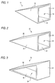
- Figs. 1 through 3 are perspective views showing preferred examples of the structure of the electric wave absorber according to the present invention.
- the electric wave absorber 11 shown in Fig. 1 is provided as a quadrangular pyramid-shaped structure.
- the electric wave absorber 11 has isosceles triangle-shaped side wall portions 12, and an opening 14 provided in its base portion while its inside is provided as a hollow structure in order to reduce its weight.
- Such an electric wave absorber 11 can be produced by: a method in which plate-like electric wave absorbers according to the present invention are bonded to one another by an inorganic adhesive agent to thereby form a quadrangular pyramid shape; a method in which quadrangular pyramid-shaped female and male molds are prepared so that a slurry for an electric wave absorber is injected in a gap portion between the two molds, dried to be solidified and then taken out of the molds; or the like.
- nonflammable layer is to be provided to the electric wave absorber 11
- nonflammable layers are preferably integrally bonded to at least exposed surfaces (surfaces of the four side wall portions 12) of the electric wave absorbers.
- the electric wave absorber 11 having such nonflammable layers can be produced by: a method in which plate-like electric wave absorbers each having a nonflammable layer integrally bonded to at least one side of the electric wave absorber according to the present invention are bonded to one another by an inorganic adhesive agent with the nonflammable layer turning outward to thereby form a quadrangular pyramid shape; a method in which quadrangular pyramid-shaped female and male molds are prepared, a nonflammable layer (in this case, a nonflammable sheet or a nonflammable sheet provided with an inorganic coating agent layer by applying and curing an inorganic coating agent in advance) is disposed in the inside of the female mold in advance, a slurry for an electric wave absorber is injected in a gap portion between the two molds and dried to be solidified and then the electric wave absorber having nonflammable layers integrally bonded thereto is taken out of the molds; or the like.
- the electric wave absorber 21 shown in Fig. 2 is provided as a wedge-shaped structure.
- the electric wave absorber 21 has inclined portions 22, side wall portions 23 located between the inclined portions, and an opening 24 which is provided in its base portion while its inside is provided as a hollow structure in order to reduce its weight.
- Such an electric wave absorber 21 can be produced by: a method in which plate-like electric wave absorbers according to the present invention are bonded to one another by an inorganic adhesive agent to thereby form a wedge shape; a method in which wedge-shaped female and male molds are prepared so that a slurry for an electric wave absorber is injected in a gap portion between the molds, dried to be solidified and taken out of the molds; or the like.
- nonflammable layers are preferably integrally bonded to at least exposed surfaces (respective surfaces of the inclined portions 22 and of the side wall portions 23) of the electric wave absorber.
- the electric wave absorber 21 having such nonflammable layers can be produced by: a method in which plate-like electric wave absorbers each having a nonflammable layer integrally bonded to at least one side of the electric wave absorber according to the present invention are bonded to one another by an inorganic adhesive agent with the nonflammable layer turning outward to thereby form a wedge shape; a method in which wedge-shaped female and male molds are prepared, a nonflammable layer (in this case, a nonflammable sheet or a nonflammable sheet provided with an inorganic coating agent layer by applying and curing an inorganic coating agent in advance) is disposed in the inside of the female mold in advance, a slurry for an electric wave absorbing molded body is injected in a gap portion between the two molds and
- the electric wave absorber 31 shown in Fig. 3 is provided as a wedge-shaped structure.
- the electric wave absorber 31 has inclined portions 32, a base portion 33 located in the base of the inclined portions, and openings 34 which are provided between the inclined portions while its inside is provided as a hollow structure in order to reduce its weight.
- Such an electric wave absorber 31 can be produced by: a method in which plate-like electric wave absorbers according to the present invention are bonded to one another by an inorganic adhesive agent to thereby form a wedge shape; or the like.
- nonflammable layers are preferably integrally bonded to at least exposed surfaces (surfaces of the inclined portions 32) of the electric wave absorber.
- the electric wave absorber 31 having such nonflammable layers can be produced by: a method in which plate-like electric wave absorbers each having a nonflammable layer integrally bonded to at least one side of the electric wave absorber according to the present invention are bonded to one another by an inorganic adhesive agent with the nonflammable layer turning outward to thereby form a wedge shape; or the like.
- a slurry of the following composition for an electric wave absorbing molded body was prepared by use of a Henschel mixer.
- Composition of Slurry for Electric Wave Absorbing Molded Body SHIRASU balloon (mean grain size: 50 to 400 ⁇ m) (SANKILITE made by Sanki Engineering Co., Ltd.) 220 parts by weight graphite (blue-P made by Nippon Graphite Industries, Ltd.) 50 parts by weight glass fiber (6 mm-article made by Nitto Boseki Co., Ltd.) 8 parts by weight inorganic adhesive agent (FJ294 made by Tokiwa Electric Co.) 175 parts by weight water 550 parts by weight
- test piece being 200 mm long, 150 mm wide and 15 mm thick (or 16 mm thick in the case where a nonflammable sheet of paper was provided) was produced. After the test piece was left in an air-dried state, the bending strength of the test piece was measured at a pressing rate of 1 mm/min.
- a wedge-shaped electric wave absorber having a base 600 mm ⁇ 600 mm and being 1300 mm high as shown in Fig. 2 was produced from the four sheets of electric wave absorbers by use of an inorganic adhesive agent (FJ294 made by Tokiwa Electric Co.). Ferrite IB-011 (5.9 mm thick) made by TDK Corp.
- the electric wave absorbing power of the electric wave, absorber was measured at 1 GHz. That is, an electric wave was radiated onto the electric wave absorber in an electric wave dark room shown in the measurement system block diagram of Fig. 5 and the reflection wave level of the electric wave absorber was measured.
- a wedge-shaped female mold having a base 600 mm ⁇ 600 mm and an upper base 400 mm long and being 1300 mm high and a male mold corresponding to the female mold were produced so that a gap portion between the two molds was 15 mm thick.
- a releasant was applied on inner surfaces of the molds. Then, a slurry of the same composition as that used for production in Embodiment 1 was injected in the gap portion between the two molds. The slurry was dried at 60°C for 24 hours so that a wedge-shaped electric wave absorber having a base 600 mm ⁇ 600 mm and being 1300 mm high was produced as shown in Fig. 3. Then, the electric wave absorber was dried at 60°C for 7 days. The electric wave absorber had nonflammable layers of nonflammable sheets integrally bonded to exposed surfaces of a wedge-shaped structure. Further, the specific gravity of the electric wave absorber was 0.30 g/cm3. The amount of the electrically conductive member (graphite) contained in the electric wave absorbing molded body was 40 g/l.
- the nonflammable characteristic, mechanical strength and 1 GHz-electric wave absorbing power of the electric wave absorber were measured by the same measurement method as in Embodiment 1 and shown in the following Table 1.
- a slurry of the following composition for an electric wave absorbing molded body was prepared by use of Omni-mixer.
- a wedge-shaped electric wave absorber having a base 600 mm ⁇ 600 mm and being 1300 mm high as shown in Fig. 3 was produced by use of the slurry in the same manner as in Embodiment 2. Then, the electric wave absorber was dried at 60°C for 7 days. The electric wave absorber had a wedge-shaped structure. Further, the specific gravity of the electric wave absorber was 0.25 g/cm3. The amount of the electrically conductive member (carbon fiber) contained in the electric wave absorbing molded body was 5 g/l.
- the nonflammable characteristic, mechanical strength and 1 GHz-electric wave absorbing power of the electric wave absorber were measured by the same measurement method as in Embodiment 1 and shown in the following Table 1.
- a plate-like electric wave absorber was produced in the same manner as in Embodiment 1 except that the amount of graphite (blue-P made by Nippon Graphite Industries, Ltd.) in the slurry for an electric wave absorbing molded body was adjusted so that the amount of the electrically conductive member (graphite) contained in the electric wave absorbing molded body was 30 g/l.
- a wedge-shaped structure was further produced by use of the plate-like electric wave absorbers.
- the specific gravity of the electric wave absorber was 0.28 g/cm3.
- the nonflammable characteristic, mechanical strength and 1 GHz-electric wave absorbing power of the electric wave absorber were measured by the same measurement method as in Embodiment 1 and shown in the following Table 1.
- a plate-like electric wave absorber was produced in the same manner as in Embodiment 1 except that the amount of graphite (blue-P made by Nippon Graphite Industries, Ltd.) in the slurry for an electric wave absorbing molded body was adjusted so that the amount of the electrically conductive member (graphite) contained in the electric wave absorbing molded body was 50 g/l.
- a wedge-shaped structure was further produced by use of the plate-like electric wave absorbers.
- the specific gravity of the electric wave absorber was 0.32 g/cm3.
- the nonflammable characteristic, mechanical strength and 1 GHz-electric wave absorbing power of the electric wave absorber were measured by the same measurement method as in Embodiment 1 and shown in the following Table 1.
- a wedge-shaped electric wave absorber was produced in the same manner as in Embodiment 3 except that the amount of carbon fiber (DIALEAD made by Mitsubishi Chemical Corp.) in the slurry for an electric wave absorbing molded body was adjusted so that the amount of the electrically conductive member (carbon fiber) contained in the electric wave absorbing molded body was 0.5 g/l.
- the specific gravity of the electric wave absorber was 0.25 g/cm3.
- the nonflammable characteristic, mechanical strength and 1 GHz-electric wave absorbing power of the electric wave absorber were measured by the same measurement method as in Embodiment 1 and shown in the following Table 1.
- a wedge-shaped electric wave absorber was produced in the same manner as in Embodiment 3 except that the amount of carbon fiber (DIALEAD made by Mitsubishi Chemical Corp.) in the slurry for an electric wave absorbing molded body was adjusted so that the amount of the electrically conductive member (carbon fiber) contained in the electric wave absorbing molded body was 15 g/l.
- the specific gravity of the electric wave absorber was 0.28 g/cm3.
- the nonflammable characteristic, mechanical strength and 1 GHz-electric wave absorbing power of the electric wave absorber were measured by the same measurement method as in Embodiment 1 and shown in the following Table 1.
- a nonflammable sheet (GP19 (0.27 mm thick) made by Tokiwa Electric Co.) to form a nonflammable layer was disposed in the inside of a mold in advance.
- a plate-like electric wave absorber having nonflammable sheets integrally provided on its opposite sides respectively and having a size 650 mm ⁇ 1400 mm ⁇ 15 mm was produced by injecting a slurry of the same composition as that used for production in Embodiment 1 into the mold and then drying the slurry at 60°C for 24 hours. Then, a wedge-shaped structure was produced in the same manner as in Example 1 by use of the plate-like electric wave absorbers.
- the specific gravity of the electric wave absorber was 0.28 g/cm3.
- the amount of the electrically conductive member (graphite) contained in the electric wave absorber was 40 g/l. Further, the nonflammable characteristic, mechanical strength and 1 GHz-electric wave absorbing power of the electric wave absorber were measured by the same measurement method as in Embodiment 1 and shown in the following Table 1.
- composition of Slurry for Electric Wave Absorber SHIRASU balloon (mean grain size: 50 to 400 ⁇ m) (SANKILITE made by Sanki Engineering Co., Ltd.) 220 parts by weight graphite (blue-P made by Nippon Graphite Industries, Ltd.) 50 parts by weight inorganic adhesive agent (FJ294 made by Tokiwa Electric Co.) 175 parts by weight water 550 parts by weight
- the aforementioned slurry was injected in a mold and dried at 60°C for 24 hours to thereby produce a plate-like electric wave absorber having a size 650 mm ⁇ 1400 mm ⁇ 15 mm. Then, the electric wave absorber was dried at 60°C for 7 days.
- the specific gravity of the electric wave absorber was 0.31 g/cm3.
- the amount of the electrically conductive member (graphite) contained in the electric wave absorber was 40 g/l. Further, the nonflammable characteristic and mechanical strength of the electric wave absorber were measured by the same measurement method as in Embodiment 1 and shown in the following Table 1.
- a wedge-shaped electric wave absorber having a base 600 mm ⁇ 600 mm and being 1300 mm high as shown in Fig. 2 was produced by use of the aforementioned plate-like electric wave absorber in the same manner as in Example 1.
- the electric wave absorbing power of the electric wave absorber was measured at 1 GHz by the same measurement method as in Example 1. Results were shown in the following Table 1.
- Example A1 0.31 Good (763°C) 2.7 -23
- Example A2 0.30 Good (761°C) 2.5 -23
- Example A3 0.25 Good (766°C) 3.5 -28
- Example A4 0.28 Good (765°C) 2.7 -21
- Example A5 0.32 Good (767°C) 3.0 -25
- Example A6 0.25 Good (760°C) 4.0 -21
- the electric wave absorber exhibits excellent electric wave absorbing power because of both the electrically conductive member and the powdered or granulated material of the inorganic hollow body which are contained in the electric wave absorber. Further, the electric wave absorber has excellent mechanical strength because of the inorganic reinforcing fiber which is contained in the electric wave absorber. Further, the electric wave absorber has excellent nonflammable characteristic because of both the powdered or granulated material of the inorganic hollow body and the inorganic reinforcing fiber which are contained in the electric wave absorber.
- the electric wave absorber is excellent in electric wave absorbing power, wide in electric wave absorption frequency band and high in withstanding electric power but also the electric wave absorber is light in weight, and excellent both in mechanical strength and in nonflammable characteristic. Accordingly, not only safety in work environment can be enhanced but also reduction of production cost can be achieved.
- Fig. 5 is a schematic sectional view showing an embodiment of the electric wave absorber according to the present invention.
- the electric wave absorber 1 has an electric wave absorbing molded body 2, and nonflammable layers 3 which are integrally bonded to opposite sides of the electric wave absorbing molded body.
- the electric wave absorbing molded body 2 which is one of constituent members of the electric wave absorber 1, is formed by bonding an electrically conductive member and a powdered or granulated material of an inorganic hollow body with each other by an inorganic adhesive agent or by bonding an electrically conductive member, a powdered or granulated material of an inorganic hollow body and inorganic reinforcing fiber to one another by an inorganic adhesive agent.
- At least one member of the group consisting of carbon black, graphite, and carbon fiber can be used as the electrically conductive member.
- Carbon black and/or graphite heretofore used as a lossy material for absorbing electric waves may be used as the electrically conductive member.
- the amount of carbon black and/or graphite contained in the electric wave absorbing molded body 2 is in a range of from 10 to 80 g/l, preferably in a range of from 30 to 50 g/l.
- carbon fiber used as the electrically conductive member is not limited specifically in terms of fiber length, density and shape. For example, carbon fiber having a fiber length of from about 3 to about 20 mm can be used.
- the amount of carbon fiber contained in the electric wave absorbing molded body 2 is in a range of from 0.5 to 15 g/l, preferably in a range of from 1 to 10 g/l.
- the electric wave absorbing molded body 2 If the amount of the electrically conductive member contained in the electric wave absorbing molded body 2 is out of the aforementioned range, the electric wave absorbing molded body 2 hardly exhibits sufficient electric wave absorbing power and the nonflammable characteristic of the electric wave absorbing molded body 2 is lowered undesirably.
- One member or a combination of two or more members of the group consisting of SHIRASU balloons, silica balloons, glass beads, and alumina-silica balloons, can be used as the powdered or granulated material of the inorganic hollow body.
- the mean grain size of the inorganic hollow body is contrariwise larger than 1000 ⁇ m, the loading density of the inorganic hollow body in the electric wave absorbing molded body 2 becomes so low that the amount of use of the inorganic adhesive agent higher in specific gravity increases to enhance the adhesive strength between grains. Also in this case, the weight of the electric wave absorber 1 increases undesirably.
- the inorganic hollow body small in mean grain size as described above is used to make reduction of weight possible compared with the background-art case where an inorganic hollow body having a mean grain size in a range of from about 1.5 to about 4.5 mm is used.
- An adhesive agent capable of being cured by hydration such as Portland cement, gypsum, or the like, or an inorganic adhesive agent such as phosphoric acid salt, silica sol, a water-glass composition, or the like can be used as the inorganic adhesive agent.
- a water-glass composition which is inexpensive and high in cementing characteristic can be used preferably.
- Water-glass is an aqueous solution containing alkaline metal silicate as a main component.
- sodium silicate is preferable because it is inexpensive and easily available as an article standardized according to JIS. Further, a mixture of water-glass of sodium silicate and water-glass of lithium silicate may be used.
- the water-glass composition is prepared by mixing a curing agent with the aforementioned water-glass in order to shorten the curing time and improve both water resistance and heat resistance.
- the curing agent include: borates such as zinc borate, potassium borate, etc.; polyvalent metal oxides such as zinc oxide, etc.; polyvalent metal hydroxides such as calcium hydroxide, etc.; silicates such as calcium silicate, etc.; and so on.
- zinc borate is the best of these.
- the curing time of the water-glass composition can be adjusted suitably within a range of from about 5 minutes to about 1 hour it 10 to 20 parts by weight of zinc borate are added to 100 parts by weight of water-glass.
- the electric wave absorbing molded body 2 as one of constituent members of the electric wave absorber 1 is made to contain inorganic reinforcing fiber as a reinforcing material in addition to the powdered or granulated material of the inorganic hollow body
- examples of the inorganic reinforcing fiber used include glass fiber, rock wool fiber, stainless steel fiber, silica-alumina fiber, potassium titanate fiber, and so on.
- the amount of the inorganic reinforcing fiber which can be contained in the electric wave absorbing molded body 2 is in range of from 1 to 20 g/l.
- the aforementioned electric wave absorbing molded body 2 can be formed by injecting a slurry containing the electrically conductive member, the inorganic hollow body, (the inorganic reinforcing fiber it necessary), the inorganic adhesive agent and water into a predetermined-shape mold.
- the electric wave absorbing molded body 2 is very advantageous in terms of reduction of the weight of the electric wave absorber 1 because the specific gravity of the electric wave absorbing molded body 2 is small to be in a range of from about 0.20 to about 0.35 g/cm3.
- the nonflammable layer 3 as one of constituent members of the electric wave absorber 1 according to the present invention is any one of a nonflammable layer constituted by a nonflammable sheet made from a slurry containing sepiolite as a main component, a nonflammable layer constituted by an inorganic coating agent layer, and a nonflammable layer constituted by a laminate formed by laminating the inorganic coating agent layer on at least one portion of the nonflammable sheet.
- the electric wave absorbing molded body 2 contains no inorganic reinforcing fiber, it is small in mechanical strength in spite of low specific gravity and light weight so that dust may be generated upon collision because the inorganic hollow body or the electrically conductive member drops out.
- the nonflammable layer 3 is disposed so as to cover the electric wave absorbing molded body 2 for giving mechanical strength and for giving nonflammable characteristic.
- the slurry for making the nonflammable sheet used as the nonflammable layer 3 contains 60 to 90 % by weight of sepiolite and further contains a binder.
- the slurry may further contain glass fiber as a reinforcing material.
- the binder used may contain a thermoplastic resin for enhancing the strength of the nonflammable sheet, and a thermosetting resin having a network three-dimensional structure for giving both cohesive characteristic and water resistance.
- a thermoplastic resin an anionic thermoplastic resin such as polyacrylamide (molecular weight: about 800000 to about 1000000), or the like, may be used.
- a cationic thermosetting resin such as polyamide-polyamine-epichlorhydrine, or the like, may be used.
- a sheet formed from the aforementioned slurry by a paper-making process is dried at a predetermined temperature, the sheet is solidified with the advance of both vaporization of water and reaction of the binder.
- a nonflammable sheet is obtained.
- a laminate formed by sandwiching inorganic fiber by two sheets formed by a paper-making process may be dried at a predetermined temperature so as to be provided as a nonflammable sheet.
- the thickness of such a nonflammable sheet is preferably in a range of from about 0.1 to about 0.5 mm.
- the inorganic fiber is glass fiber, carbon fiber, or the like, and its fiber thickness, density and shape are not limited specifically.
- the inorganic coating agent used in the nonflammable layer 3 is not limited specifically but a material heretofore used as an inorganic coating agent having nonflammable or flame-resisting characteristic can be used.
- the inorganic coating agent may be an inorganic coating agent containing alkyl silicate as a main agent, water for hydrolyzing the alkyl silicate, aluminum chelate as a reaction catalyst for accelerating the hydrolyzing reaction, methyl acid-phosphate as a reaction decelerator for decelerating the hydrolyzing reaction, and alcohol as a solvent for dissolving the alkyl silicate and water.
- the inorganic coating agent may further contain sepiolite dispersed in alcohol as the aforementioned solvent, and further contain carbon graphite, etc.
- the alkyl silicate used examples include methyl trimethoxysilane, phenyl trimethoxysilane, etc.
- a water type inorganic coating agent may be used.
- the thickness of the inorganic coating agent layer formed from the aforementioned inorganic coating agent is preferably in a range of from about 10 to about 30 ⁇ m.
- the integral bonding of the nonflammable layer 3 onto the electric wave absorbing molded body 2 is performed by: (1) a method in which the nonflammable sheet or the nonflammable sheet provided with the inorganic coating agent layer by applying and curing the inorganic coating agent in advance is bonded to the electric wave absorbing molded body 2 by the inorganic adhesive agent so that the nonflammable layer 3 is integrally bonded onto the electric wave absorbing molded body 2; (2) a method in which the inorganic coating agent is applied on the electric wave absorbing molded body 2 and cured so that the nonflammable layer 3 made from the inorganic coating agent layer is integrally bonded onto the electric wave absorbing molded body 2; (3) a method in which the nonflammable sheet or the nonflammable sheet provided with the inorganic coating agent layer by applying and curing the inorganic coating agent in advance is disposed on an inner surface of the mold prepared for the slurry to be injected therein to mold the electric wave absorbing molded body 2 so that both the electric wave absorbing molded body 2 and the
- the thickness of the plate-like electric wave absorber 1 shown in Fig. 5 is preferably in a range of from about 10 to about 30 mm.
- the nonflammable layer 3 is integrally bonded to at least one portion of the electric wave absorbing molded body 2 to improve the mechanical strength of the electric wave absorbing molded body 2. That is, it is not essential that nonflammable layers are provided on opposite sides of the electric wave absorbing molded body 2 respectively as shown in Fig. 5.
- Figs. 1 through 3 are perspective views showing preferred examples of the structure of the electric wave absorber according to the present invention.
- the electric wave absorber 11 shown in Fig. 1 is provided as a quadrangular pyramid-shaped structure.
- the electric wave absorber 11 has isosceles triangle-shaped side wall portions 12, and an opening 14 provided in its base portion while its inside is provided as a hollow structure in order to reduce its weight.
- nonflammable layers are integrally bonded to at least exposed surfaces (surfaces of the four side wall portions 12).
- Such an electric wave absorber can be produced by: a method in which plate-like electric wave absorbers each having a nonflammable layer integrally bonded to at least one side of the side wall portion according to the present invention are bonded to one another by an inorganic adhesive agent with the nonflammable layer turning outward so as to form a quadrangular pyramid shape; a method in which quadrangular pyramid-shaped female and male molds are prepared, a nonflammable layer (in this case, a nonflammable sheet or a nonflammable sheet provided with an inorganic coating agent layer by applying and curing an inorganic coating agent in advance) is disposed in the inside of the female mold in advance, a slurry for an electric wave absorbing molded body is injected in a gap portion between the two molds and dried to be solidified and then the electric wave absorbing molded body integrally bonded to the nonflammable layer is taken out of the molds; or the like.
- the electric wave absorber 21 shown in Fig. 2 is provided as a wedge-shaped structure.
- the electric wave absorber 21 has inclined portions 22, sidewall portions 23 located between the inclined portions, and an opening 24 which is provided in its base portion while its inside is provided as a hollow structure in order to reduce its weight.
- nonflammable layers are integrally bonded to at least exposed surfaces (respective surfaces of the inclined portions 22 and of the side wall portions 23).
- Such an electric wave absorber can be produced by: a method in which plate-like electric wave absorbers each having a nonflammable layer integrally bonded to at least one side of the inclined portion or the side wall portion according to the present invention are bonded to one another by an inorganic adhesive agent with the nonflammable layer turning outward so as to form a wedge; a method in which wedge-shaped female and male molds are prepared, a nonflammable layer (in this case, a nonflammable sheet or a nonflammable sheet provided with an inorganic coating agent layer by applying and curing an inorganic coating agent in advance) is disposed in the inside of the female mold in advance, a slurry for an electric wave absorbing molded body is injected in a gap portion between the two molds and dried to be solidified and then the electric wave absorbing molded body integrally bonded to the nonflammable layer is taken out of the molds; or the like.
- a nonflammable layer in this case, a nonflammable sheet or a nonflammable sheet provided with an in
- the electric wave absorber 31 shown in Fig. 3 is provided as a wedge-shaped structure.
- the electric wave absorber 31 has inclined portions 32, a base portion 33 located in the base of the inclined portions, and openings 34 which are provided between the inclined portions while its inside is provided as a hollow structure in order to reduce its weight.
- nonflammable layers are integrally bonded to at least exposed surfaces (surfaces of the inclined portions 32).
- Such an electric wave absorber can be produced by: a method in which plate-like electric wave absorbers each having a nonflammable layer integrally bonded to at least one side surface according to the present invention are bonded to one another by an inorganic adhesive agent with the nonflammable layer turning outward so as to form a wedge shape; or the like.
- a slurry of the following composition for an electric wave absorbing molded body was prepared by use of a Henschel mixer.
- Composition of Slurry for Electric Wave Absorbing Molded Body SHIRASU balloon (mean grain size; 50 to 400 ⁇ m) (SANKILITE made by Sanki Engineering Co., Ltd.) 220 parts by weight graphite (blue-P made by Nippon Graphite Industries, Ltd.) 50 parts by weight glass fiber (6 mm-article made by Nitto Boseki Co., Ltd.) 8 parts by weight inorganic adhesive agent (FJ294 made by Tokiwa Electric Co.) 175 parts by weight water 550 parts by weight
- the aforementioned slurry was injected in a mold in which a nonflammable sheet (GP19 (0.27 mm thick) made by Tokiwa Electric Co.) to form a nonflammable layer was disposed in the inside of the mold in advance.
- the slurry was dried at 60°C for 24 hours so that a plate-like electric wave absorber having a size 650 mm ⁇ 1400 mm ⁇ 15 mm and having a sectional structure shown in Fig. 5 was produced.
- the electric wave absorber was dried at 60°C for 7 days.
- the specific gravity of the electric wave absorber was 0.32 g/cm3.
- the amount of the electrically conductive member (graphite) contained in the electric wave absorbing molded body was 40 g/l. Further, both nonflammable characteristic and mechanical strength were measured by the following measurement method and shown in the following Table 2.
- test piece being 200 mm long, 150 mm wide and 15 mm thick (or 16 mm thick in the case where a nonflammable sheet of paper was provided) was produced. After the test piece was left in an air-dried state, the bending strength of the test piece was measured at a pressing rate of 1 mm/min.
- a wedge-shaped electric wave absorber having a base 600 mm ⁇ 600 mm and being 1300 mm high as shown in Fig. 1 was produced from the four sheets of electric wave absorbers by use of an inorganic adhesive agent (FJ294 made by Tokiwa Electric Co.). Ferrite IB-011 (5.9 mm thick) made by TDK Corp.
- the electric wave absorbing power of the electric wave absorber was measured at 1 GHz. That is, an electric wave was radiated onto the electric wave absorber in an electric wave dark room shown in the measurement system block diagram of Fig. 4 and the reflection wave level of the electric wave absorber was measured.
- a wedge-shaped female mold having a base 600 mm ⁇ 600 mm and an upper base 400 mm long and being 1300 mm high and a male mold corresponding to the female mold were produced so that a gap portion between the two molds was 15 mm thick.
- a releasant was applied on inner surfaces of the molds.
- a nonflammable sheet (GP19 (0.27 mm thick) made by Tokiwa Electric) to form a nonflammable layer was disposed in the inside of the female mold in advance.
- a slurry of the same composition as that used for production in Embodiment 1 was injected in the gap portion between the two molds. The slurry was dried at 60°C for 24 hours so that a wedge-shaped electric wave absorber having a base 600 mm ⁇ 600 mm and being 1300 mm high was produced as shown in Fig. 2. Then, the electric wave absorber was dried at 60°C for 7 days.
- the electric wave absorber had nonflammable layers of nonflammable sheets integrally bonded to exposed surfaces of a wedge-shaped structure. Further, the specific gravity of the electric wave absorber was 0.31 g/cm3. The amount of the electrically conductive member (graphite) contained in the electric wave absorbing molded body was 40 g/l.
- the nonflammable characteristic, mechanical strength and 1 GHz-electric wave absorbing power of the electric wave absorber were measured by the same measurement method as in Embodiment 1 and shown in the following Table 2.
- a slurry of the following composition for an electric wave absorbing molded body was prepared by use of Omni-mixer.
- a wedge-shaped electric wave absorber having a base 600 mm ⁇ 600 mm and being 1300 mm high as shown in Fig. 2 was produced by use of the slurry in the same manner as in Embodiment 2. Then, the electric wave absorber was dried at 60°C for 7 days. The electric wave absorber had nonflammable layers of nonflammable sheets integrally bonded to exposed surfaces of a wedge-shaped structure. Further, the specific gravity of the electric wave absorber was 0.27 g/cm3. The amount of the electrically conductive member (carbon fiber) contained in the electric wave absorbing molded body was 5 g/l.
- the nonflammable characteristic, mechanical strength and 1 GHz-electric wave absorbing power of the electric wave absorber were measured by the same measurement method as in Embodiment 1 and shown in the following Table 2.
- a plate-like electric wave absorber was produced in the same manner as in Embodiment 1 except that the amount of graphite (blue-P made by Nippon Graphite Industries, Ltd.) in the slurry for an electric wave absorbing molded body was adjusted so that the amount of the electrically conductive member (graphite) contained in the electric wave absorbing molded body was 30 g/l.
- a wedge-shaped structure was further produced by use of the plate-like electric wave absorbers.
- the specific gravity of the electric wave absorber was 0.30 g/cm3.
- the nonflammable characteristic, mechanical strength and 1 GHz-electric wave absorbing power of the electric wave absorber were measured by the same measurement method as in Embodiment 1 and shown in the following Table 2.
- a plate-like electric wave absorber was produced in the same manner as in Embodiment 1 except that the amount of graphite (blue-P made by Nippon Graphite Industries, Ltd.) in the slurry for an electric wave absorbing molded body was adjusted so that the amount of the electrically conductive member (graphite) contained in the electric wave absorbing molded body was 50 g/l.
- a wedge-shaped structure was further produced by use of the plate-like electric wave absorbers.
- the specific gravity of the electric wave absorber was 0.33 g/cm3.
- the nonflammable characteristic, mechanical strength and 1 GHz-electric wave absorbing power of the electric wave absorber were measured by the same measurement method as in Embodiment 1 and shown in the following Table 2.
- a wedge-shaped electric wave absorber was produced in the same manner as in Embodiment 3 except that the amount of carbon fiber (DIALEAD made by Mitsubishi Chemical Corp.) in the slurry for an electric wave absorbing molded body was adjusted so that the amount of the electrically conductive member (carbon fiber) contained in the electric wave absorbing molded body was 0.5 g/l.
- the specific gravity of the electric wave absorber was 0.26 g/cm3.
- the nonflammable characteristic, mechanical strength and 1 GHz-electric wave absorbing power of the electric wave absorber were measured by the same measurement method as in Embodiment 1 and shown in the following Table 2.
- a wedge-shaped electric wave absorber was produced in the same manner as in Embodiment 3 except that the amount of carbon fiber (DIALEAD made by Mitsubishi Chemical Corp.) in the slurry for an electric wave absorbing molded body was adjusted so that the amount of the electrically conductive member (carbon fiber) contained in the electric wave absorbing molded body was 15 g/l.
- the specific gravity of the electric wave absorber was 0.29 g/cm3.
- the nonflammable characteristic, mechanical strength and 1 GHz-electric wave absorbing power of the electric wave absorber were measured by the same measurement method as in Embodiment 1 and shown in the following Table 2.
- a wedge-shaped electric wave absorber was produced in the same manner as in Embodiment 3 except that a nonflammable sheet provided with a 20 ⁇ m-thick inorganic coating agent layer by applying an inorganic coating agent (GRANDEX FJ803 made by Tokiwa Electric Co.) onto a nonflammable sheet (GP19 (0.27 mm thick) made by Tokiwa Electric Co.) was used as a nonflammable sheet to form a nonflammable layer.
- the electric wave absorber was formed so that nonflammable layers each made from the nonflammable sheet coated with the inorganic coating agent layer were integrally bonded to exposed surfaces of a wedge-shaped structure. Further, the specific gravity of the electric wave absorber was 0.28 g/cm3.
- the amount of the electrically conductive member (carbon fiber) contained in the electric wave absorbing molded body was 5 g/l.
- the nonflammable characteristic, mechanical strength and 1 GHz-electric wave absorbing power of the electric wave absorber were measured by the same measurement method as in Embodiment 1 and shown in the following Table 2.
- a wedge-shaped female mold having a base 600 mm ⁇ 600 mm and an upper base 400 mm long and being 1300 mm high and a male mold corresponding to the female mold were produced so that a gap portion between the two molds was 15 mm thick.
- a releasant was applied on inner surfaces of the molds.
- a slurry of the same composition as that used for production in Embodiment 3 was injected in the gap portion between the two molds.
- the slurry was dried at 60°C for 24 hours so that a wedge-shaped electric wave absorber having a base 600 mm ⁇ 600 mm and being 1300 mm high as shown in Fig. 2 was produced.
- an inorganic coating agent (GRANDEX FJ803 made by Tokiwa Electric Co.) was applied onto exposed surfaces of the electric wave absorber to provide an inorganic coating agent layer 20 ⁇ m thick.
- the electric wave absorber was dried at 60°C for 7 days.
- the electric wave absorber was formed so that nonflammable layers each made from an inorganic coating agent layer were integrally bonded to exposed surfaces of a wedge-shaped structure. Further, the specific gravity of the electric wave absorber was 0.30 g/cm3. The amount of the electrically conductive member (carbon fiber) contained in the electric wave absorbing molded body was 5 g/l.
- the nonflammable characteristic, mechanical strength and 1 GHz-electric wave absorbing power of the electric wave absorber were measured by the same measurement method as in Embodiment 1 and shown in the following Table 2.
- a slurry of the following composition for an electric wave absorbing molded body was prepared by use of a Henschel mixer.
- a plate-like electric wave absorber having a size 650 mm ⁇ 1400 mm ⁇ 15 mm and having a sectional structure shown in Fig. 5 was produced in the same manner as in Embodiment 1 except that the aforementioned slurry was used.
- the electric wave absorber was dried at 60°C for 7 days.
- the electric wave absorber was provided so that nonflammable layers each made from a nonflammable sheet were integrally bonded to opposite sides of the electric wave absorber.
- the specific gravity of the electric wave absorber was 0.33 g/cm3.
- the amount of the electrically conductive member (graphite) contained in the electric wave absorbing molded body was 40 g/l.
- the nonflammable characteristic and mechanical strength of the electric wave absorber were measured by the same measurement method as in Embodiment 1 and shown in the following Table 2.
- Composition of Slurry for Electric Wave Absorbing Molded Body SHIRASU balloon (mean grain size: 50 to 400 ⁇ m) (SANKILITE made by Sanki Engineering Co., Ltd.) 220 parts by weight graphite (blue-P made by Nippon Graphite Industries, Ltd.) 50 parts by weight inorganic adhesive agent (FJ294 made by Tokiwa Electric Co.) 175 parts by weight water 550 parts by weight
- a wedge-shaped electric wave absorber was produced by use of the aforementioned plate-like electric wave absorber in the same manner as in Example 1.
- the electric wave absorbing power of the electric wave absorber was measured at 1 GHz by the same measurement method as in Embodiment 1 and shown in the following Table 2.
- a slurry of the following composition for an electric wave absorbing molded body was prepared by a Henschel mixer.
- Composition of Slurry for Electric Wave Absorbing Molded Body SHIRASU balloon (mean grain size: 50 to 400 ⁇ m) (SANKILITE made by Sanki Engineering Co., Ltd.) 220 parts by weight graphite (blue-P made by Nippon Graphite Industries, Ltd.) 50 parts by weight inorganic adhesive agent (FJ294 made by Tokiwa Electric Co.) 175 parts by weight water 550 parts by weight
- the aforementioned slurry was injected in a mold and dried at 60°C for 24 hours so that a plate-like electric wave absorber having a size 650 mm ⁇ 1400 mm ⁇ 15 mm was produced. Then, the electric wave absorber was dried at 60°C for 7 days.
- the specific gravity of the electric wave absorber was 0.31 g/cm3.
- the amount of the electrically conductive member (graphite) contained in the electric wave absorber was 40 g/l.
- the nonflammable characteristic and mechanical strength of the electric wave absorber were measured by the same measurement method as in Example 1 and shown in the following Table 2.
- a wedge-shaped electric wave absorber having a base 600 mm ⁇ 600 mm and being 1300 mm high as shown in Fig. 2 was produced by use of the aforementioned plate-like electric wave absorber in the same manner as in Example 1.
- the electric wave absorbing power of the electric wave absorber was measured at 1 GHz by the same measurement method as in Embodiment 1 and shown in the following Table 2.
- Example B1 0.32 Good (761°C) 3.2 -22
- Example B2 0.31 Good (759°C) 3.0 -22
- Example B3 0.27 Good (765°C) 4.1 -28
- Example B4 0.30 Good (760°C) 3.3 -20
- Example B5 0.33 Good (764°C) 2.8 -24
- Example B6 0.26 Good (758°C) 3.5 -20
- Example B7 0.29 Good (765°C) 4.6 -21
- Example B10 0.33 Good (761°C) 2.0 -24 Comparative Example 0.31 Good (765°C) 0.4 -23
- Embodiments 1 to 10 were low in specific gravity, light in weight and excellent in nonflammable characteristic, mechanical strength and electric wave absorbing power. It was further confirmed that the characteristic was enhanced more greatly when inorganic reinforcing fiber was used in combination with a powdered or granulated material of SHIRASU balloons (Examples 1 to 9).
- the electric wave absorbing molded body as one of constituent members of the electric wave absorber exhibits excellent electric wave absorbing power but also the nonflammable layer integrally bonded to the electric wave absorbing molded body gives both mechanical strength and nonflammable characteristic to the electric wave absorber. Accordingly, the electric wave absorber is excellent in electric wave absorbing power, wide in electric wave absorption frequency band and high in withstanding electric power. Furthermore, the electric wave absorber is light in weight and excellent both in mechanical strength and in nonflammable characteristic. Accordingly, not only safety in work environment can be improved but also reduction of production cost can be achieved.
Landscapes
- Engineering & Computer Science (AREA)
- Microelectronics & Electronic Packaging (AREA)
- Shielding Devices Or Components To Electric Or Magnetic Fields (AREA)
Applications Claiming Priority (4)
| Application Number | Priority Date | Filing Date | Title |
|---|---|---|---|
| JP26724298 | 1998-09-04 | ||
| JP10267241A JP2000082892A (ja) | 1998-09-04 | 1998-09-04 | 電波吸収体 |
| JP26724198 | 1998-09-04 | ||
| JP10267242A JP2000082893A (ja) | 1998-09-04 | 1998-09-04 | 電波吸収体 |
Publications (2)
| Publication Number | Publication Date |
|---|---|
| EP0986294A2 true EP0986294A2 (de) | 2000-03-15 |
| EP0986294A3 EP0986294A3 (de) | 2000-05-17 |
Family
ID=26547777
Family Applications (1)
| Application Number | Title | Priority Date | Filing Date |
|---|---|---|---|
| EP99117274A Withdrawn EP0986294A3 (de) | 1998-09-04 | 1999-09-02 | Absorber für elektrische Wellen |
Country Status (4)
| Country | Link |
|---|---|
| US (1) | US6259394B1 (de) |
| EP (1) | EP0986294A3 (de) |
| KR (1) | KR20000022855A (de) |
| TW (1) | TW428801U (de) |
Cited By (4)
| Publication number | Priority date | Publication date | Assignee | Title |
|---|---|---|---|---|
| WO2003064780A1 (fr) * | 2002-01-31 | 2003-08-07 | Nitto Boseki Co., Ltd. | Absorbeur d'ondes electromagnetiques |
| DE102007058480A1 (de) * | 2007-12-04 | 2009-06-10 | Frankonia Handels- und Vertriebsgesellschaft für chemisch- und elektrotechnische Produkte mbH | Absorber zur breitbandigen Absorption von elektromagnetischen Wellen im Frequenzbereich von 1 bis 18 GHz und Verfahren zu dessen Herstellung |
| CN1905422B (zh) * | 2006-08-07 | 2010-05-12 | 信息产业部通信计量中心 | 同时具备空中射频测试与电磁兼容性测试能力的全电波暗室 |
| CN114383386A (zh) * | 2022-01-22 | 2022-04-22 | 和爱电磁兼容科技(安徽)有限公司 | 一种吸波材料用表面除湿结构 |
Families Citing this family (7)
| Publication number | Priority date | Publication date | Assignee | Title |
|---|---|---|---|---|
| JP3922039B2 (ja) * | 2002-02-15 | 2007-05-30 | 株式会社日立製作所 | 電磁波吸収材料及びそれを用いた各種製品 |
| US7290057B2 (en) | 2002-08-20 | 2007-10-30 | Microsoft Corporation | Media streaming of web content data |
| JP4144754B2 (ja) * | 2004-05-31 | 2008-09-03 | Tdk株式会社 | 電波吸収体 |
| US7688246B2 (en) * | 2005-05-10 | 2010-03-30 | Fuji Xerox Co., Ltd. | Radio wave absorber, electromagnetic field measurement system and radiated immunity system |
| US8324515B2 (en) | 2007-10-16 | 2012-12-04 | Honeywell International Inc. | Housings for electronic components |
| US20090117386A1 (en) * | 2007-11-07 | 2009-05-07 | Honeywell International Inc. | Composite cover |
| US7869216B2 (en) * | 2008-08-25 | 2011-01-11 | Honeywell International Inc. | Composite avionics chassis |
Family Cites Families (19)
| Publication number | Priority date | Publication date | Assignee | Title |
|---|---|---|---|---|
| NL112646C (de) * | 1958-12-04 | |||
| JPS5734396A (en) | 1980-08-08 | 1982-02-24 | Tdk Electronics Co Ltd | Radio wave absorbing composition |
| JPS5734398A (en) | 1980-08-11 | 1982-02-24 | Tdk Electronics Co Ltd | Radio wave absorbing composition |
| DE3818114A1 (de) * | 1988-05-27 | 1989-11-30 | Gruenzweig & Hartmann Montage | Absorber fuer elektromagnetische und akustische wellen |
| US5248553A (en) * | 1989-03-16 | 1993-09-28 | Toyo Ink Manufacturing Co., Ltd. | Coated molded article |
| US5324766A (en) * | 1989-07-07 | 1994-06-28 | Mitsui Petrochemical Industries, Ltd. | Resin composition for forming plated layer and use thereof |
| JPH0399496A (ja) * | 1989-09-12 | 1991-04-24 | Gureesu Japan Kk | 電波吸収体 |
| JPH05280121A (ja) | 1991-03-16 | 1993-10-26 | Tokiwa Electric Co Ltd | 強化不燃シート |
| JP2743227B2 (ja) | 1992-02-26 | 1998-04-22 | パラマウント硝子工業株式会社 | 耐熱不燃性電波吸収体 |
| US5455116A (en) * | 1992-10-27 | 1995-10-03 | Kansai Paint Co., Ltd. | Electromagnetic wave reflection-preventing material and electromagnetic wave reflection-preventing method |
| US5455117A (en) * | 1992-10-27 | 1995-10-03 | Kansai Paint Co., Ltd. | Electromagnetic wave reflection-preventing material and electromagnetic wave reflection-preventing method |
| JP2826038B2 (ja) * | 1993-04-28 | 1998-11-18 | 大塚サイエンス株式会社 | 電波吸収体およびその製造方法 |
| EP0689262B1 (de) * | 1994-06-23 | 1999-12-01 | Takenaka Corporation | Wellenabsorbierende Zusammensetzung, Absorberelement für Funkwellen, Funkwellenabsorber und Verfahren zur Herstellung von Absorberelementen |
| JPH081854A (ja) | 1994-06-27 | 1996-01-09 | Tokiwa Electric Co Ltd | 耐火ボード |
| JPH0883992A (ja) * | 1994-09-12 | 1996-03-26 | Natl Space Dev Agency Japan<Nasda> | 電波吸収体 |
| JPH09148779A (ja) * | 1995-11-17 | 1997-06-06 | Ohbayashi Corp | 電磁波の遮蔽・吸収性を有するコンクリート構造 |
| JP3664192B2 (ja) | 1996-01-29 | 2005-06-22 | 北越製紙株式会社 | 不燃シートまたは不燃成形体 |
| JPH10217217A (ja) * | 1997-02-07 | 1998-08-18 | Mitsubishi Chem Corp | 錐状電波吸収体の製造法 |
| JPH1187978A (ja) * | 1997-09-09 | 1999-03-30 | Nitto Boseki Co Ltd | 不燃性電波吸収体 |
-
1999
- 1999-09-02 KR KR1019990037040A patent/KR20000022855A/ko not_active Abandoned
- 1999-09-02 EP EP99117274A patent/EP0986294A3/de not_active Withdrawn
- 1999-09-03 US US09/390,293 patent/US6259394B1/en not_active Expired - Fee Related
- 1999-09-04 TW TW088215155U patent/TW428801U/zh not_active IP Right Cessation
Cited By (4)
| Publication number | Priority date | Publication date | Assignee | Title |
|---|---|---|---|---|
| WO2003064780A1 (fr) * | 2002-01-31 | 2003-08-07 | Nitto Boseki Co., Ltd. | Absorbeur d'ondes electromagnetiques |
| CN1905422B (zh) * | 2006-08-07 | 2010-05-12 | 信息产业部通信计量中心 | 同时具备空中射频测试与电磁兼容性测试能力的全电波暗室 |
| DE102007058480A1 (de) * | 2007-12-04 | 2009-06-10 | Frankonia Handels- und Vertriebsgesellschaft für chemisch- und elektrotechnische Produkte mbH | Absorber zur breitbandigen Absorption von elektromagnetischen Wellen im Frequenzbereich von 1 bis 18 GHz und Verfahren zu dessen Herstellung |
| CN114383386A (zh) * | 2022-01-22 | 2022-04-22 | 和爱电磁兼容科技(安徽)有限公司 | 一种吸波材料用表面除湿结构 |
Also Published As
| Publication number | Publication date |
|---|---|
| KR20000022855A (ko) | 2000-04-25 |
| US6259394B1 (en) | 2001-07-10 |
| EP0986294A3 (de) | 2000-05-17 |
| TW428801U (en) | 2001-04-01 |
Similar Documents
| Publication | Publication Date | Title |
|---|---|---|
| US6259394B1 (en) | Electric wave absorber | |
| AU2004247667B2 (en) | Multi-layer fire-barrier systems | |
| KR100333568B1 (ko) | 불연성 허니컴 전파흡수재 및 이를 사용한 전파흡수체 | |
| KR100472198B1 (ko) | 전파흡수체 조립용 부재, 전파흡수체 및 전파흡수체의제조방법 | |
| US5932054A (en) | Radio wave absorber composition, radio wave absorber member, radio wave absorber, and method for producing radio wave absorber member | |
| US6613975B1 (en) | Member for assembling radio wave absorber and method of producing radio wave absorber | |
| JP4375987B2 (ja) | 電波吸収体用成型体およびその製造方法、ならびに電波吸収体 | |
| JP2000082893A (ja) | 電波吸収体 | |
| JP2000277973A (ja) | フェライト含有繊維体及びその製造方法 | |
| JP2000082892A (ja) | 電波吸収体 | |
| JP2002176286A (ja) | 不燃性電波吸収シート及び不燃性電波吸収三次元構造体 | |
| KR100447887B1 (ko) | 전파투과체 | |
| JPH051386Y2 (de) | ||
| JP2000135752A (ja) | 電波透過体 | |
| CN222146380U (zh) | 隔热板、电池模组、电池包和用电设备 | |
| JP4005371B2 (ja) | 表面被覆電波吸収体 | |
| JPH07144977A (ja) | 吸音性複合成形体およびその製法 | |
| JPS63208300A (ja) | 電波吸収体 | |
| JP4420145B2 (ja) | 電波暗室 | |
| JP2903165B2 (ja) | 不燃性電波吸収材の製造方法 | |
| JPH0661890B2 (ja) | 不燃性吸音材並びにその製造法 | |
| JPH0227798A (ja) | 電波吸収体及びその製造方法 | |
| JP2006287018A (ja) | 電波吸収シート | |
| JPH01223242A (ja) | 電磁波遮蔽吸収断熱材 |
Legal Events
| Date | Code | Title | Description |
|---|---|---|---|
| PUAI | Public reference made under article 153(3) epc to a published international application that has entered the european phase |
Free format text: ORIGINAL CODE: 0009012 |
|
| AK | Designated contracting states |
Kind code of ref document: A2 Designated state(s): DE FR GB NL |
|
| AX | Request for extension of the european patent |
Free format text: AL;LT;LV;MK;RO;SI |
|
| PUAL | Search report despatched |
Free format text: ORIGINAL CODE: 0009013 |
|
| AK | Designated contracting states |
Kind code of ref document: A3 Designated state(s): AT BE CH CY DE DK ES FI FR GB GR IE IT LI LU MC NL PT SE |
|
| AX | Request for extension of the european patent |
Free format text: AL;LT;LV;MK;RO;SI |
|
| 17P | Request for examination filed |
Effective date: 20000803 |
|
| AKX | Designation fees paid |
Free format text: DE FR GB NL |
|
| STAA | Information on the status of an ep patent application or granted ep patent |
Free format text: STATUS: THE APPLICATION IS DEEMED TO BE WITHDRAWN |
|
| 18D | Application deemed to be withdrawn |
Effective date: 20061005 |