EP0985530A2 - Farbwerk in einer Rotations-Offsetdruckmaschine mit einer Farbauftragswalze zur Verringerung des Pereffektes der Druckfarbe - Google Patents
Farbwerk in einer Rotations-Offsetdruckmaschine mit einer Farbauftragswalze zur Verringerung des Pereffektes der Druckfarbe Download PDFInfo
- Publication number
- EP0985530A2 EP0985530A2 EP99114183A EP99114183A EP0985530A2 EP 0985530 A2 EP0985530 A2 EP 0985530A2 EP 99114183 A EP99114183 A EP 99114183A EP 99114183 A EP99114183 A EP 99114183A EP 0985530 A2 EP0985530 A2 EP 0985530A2
- Authority
- EP
- European Patent Office
- Prior art keywords
- inking
- ink
- roller
- shore
- outer layer
- Prior art date
- Legal status (The legal status is an assumption and is not a legal conclusion. Google has not performed a legal analysis and makes no representation as to the accuracy of the status listed.)
- Granted
Links
- 229920001971 elastomer Polymers 0.000 claims abstract description 11
- 239000000806 elastomer Substances 0.000 claims abstract description 9
- 238000007645 offset printing Methods 0.000 claims abstract description 7
- 230000004323 axial length Effects 0.000 claims abstract description 5
- 238000007639 printing Methods 0.000 claims description 19
- 244000059549 Borneo rubber Species 0.000 claims 1
- 238000011144 upstream manufacturing Methods 0.000 claims 1
- 239000007787 solid Substances 0.000 abstract description 6
- 239000000976 ink Substances 0.000 description 42
- 239000000463 material Substances 0.000 description 6
- 230000003287 optical effect Effects 0.000 description 4
- 239000003973 paint Substances 0.000 description 4
- 230000000694 effects Effects 0.000 description 3
- 239000011049 pearl Substances 0.000 description 3
- 239000002826 coolant Substances 0.000 description 2
- 238000001816 cooling Methods 0.000 description 2
- 206010037867 Rash macular Diseases 0.000 description 1
- 229910000831 Steel Inorganic materials 0.000 description 1
- 150000001875 compounds Chemical class 0.000 description 1
- 238000005094 computer simulation Methods 0.000 description 1
- 230000001419 dependent effect Effects 0.000 description 1
- 230000008021 deposition Effects 0.000 description 1
- 238000006073 displacement reaction Methods 0.000 description 1
- 238000005516 engineering process Methods 0.000 description 1
- 238000004519 manufacturing process Methods 0.000 description 1
- 238000013021 overheating Methods 0.000 description 1
- 239000010959 steel Substances 0.000 description 1
Images


Classifications
-
- B—PERFORMING OPERATIONS; TRANSPORTING
- B41—PRINTING; LINING MACHINES; TYPEWRITERS; STAMPS
- B41F—PRINTING MACHINES OR PRESSES
- B41F31/00—Inking arrangements or devices
- B41F31/26—Construction of inking rollers
Definitions
- the present invention relates to an inking unit in a rotary offset printing press with an inking roller according to the preamble of claim 1, by means of which the Pearls of the solids contained in printing inks is reduced.
- Prior art offset printing machines comprise a plate cylinder the surface of which contains the image to be printed. This is either in Roll contact with the web or sheet to be printed or preferably with a transfer or blanket cylinder, by means of which the the image contained in the plate cylinder is transferred to the web or the sheet.
- the Ink is fed to the plate cylinder, which is then either directly on the web / Transfer sheet or to the blanket cylinder and then to the web / sheet becomes.
- the ink supply to the plate cylinder can be varied Way, most often using a color box, i. H. one Device in which an ink fountain roller on a container containing printing ink, the ink fountain. At the interface between the ink fountain base and the ink fountain roller are a number of ink fountain keys, which on the Ink fountain roller to and from this can be moved. The distance one The respective ink zone screw from the ink fountain roller surface determines the thickness the ink transferred to the outer surface of the ink fountain roller. In close proximity to the ink fountain roller is a metering roller beyond the ink fountain head screws subordinate.
- the metering roller leads one of one or more rollers, e.g. B. friction rollers, Lifter rollers, intermediate rollers and inking rollers existing ink roller color to.
- the ink is transferred to the plate cylinder via the inking roller.
- inking rollers have an elastic, relatively soft Outer surface made of an elastomer, the hardness in the range between 22 and 28 Shore A (Durometer) lies.
- the outer surface is also cylindrical and has one uniform outer diameter.
- the present invention relates to a device by which the beading of the in Solids contained in printing inks is reduced. In this way, the The present invention significantly improves the printing quality of a printing press by an even distribution of the ink solids is achieved over the entire printed image. Furthermore, the present invention uses less ink achieved uniform optical density of the printed image.
- one or more are used as inking rollers Rollers used, the outer surface of which is made of an elastomer, which is a Hardness between 60 and 90 Shore A (durometer) or between 50 and 100 Shore A (Durometer).
- the use of such an inking roller ensures one more even application of paint on the plate cylinder and thus on the Blanket cylinder and the web to be printed.
- Is more than an inking roller provided is preferably at least the inking roller that the plate cylinder contacted last in the direction of rotation, as an inking roller with a hard one Outer surface made of an elastomer.
- Significantly improved printing results can be achieved, however, if all inking rollers are designed in this way.
- the inking rollers can axially along their length have a convex shape so that the diameter of the hard Surface made of an elastomer is larger in the axial center than at the axial ends, which ensures optimal contact between the inking rollers and the plate cylinder is guaranteed.
- the present invention further relates to a printing machine with which at low Color consumption achieved a high print quality and a uniform optical density can be, since the printing ink by the inking rollers according to the invention is evenly applied to the plate cylinder and thus to achieve a certain print quality less color needs to be applied. Accordingly means the present invention is an improvement over prior art printing machines the technology in which to achieve a certain print quality much more Color must be used.
- Fig. 1 shows a schematic representation of a printing press according to the present invention.
- a web of material W e.g. B. made of paper
- a blanket 12 can be applied to each of the blanket cylinders B U and B L.
- the plate cylinder and the inking unit by means of which the colored image is transferred to the upper blanket cylinder B U , are not shown.
- These components are identical or similar to the components assigned to the lower blanket cylinder B L.
- the ink application rollers F 1 , F 2 , F 3 can be supplied with ink by any known inking unit;
- an ink roller 1 is shown, through which the color is transferred to the plate cylinder P, which then transfers a color image to the lower blanket cylinder B L.
- a rotating ink fountain roller I adjoins an ink fountain 10 and takes up an ink layer therefrom in a known manner, which then transfers it to a metering roller M.
- the metering roller M transfers the ink layer to a number of transfer rollers D and then to the friction rollers V, an (oscillating) intermediate roller S and a large transfer roller L.
- the ink is transferred from the friction rollers V to one or more ink application rollers F 1 , F 2 , F 3 .
- the inking rollers F 1 , F 2 , F 3 transfer an ink layer to the plate cylinder P, although it is not absolutely necessary to provide three inking rollers, but the number of inking rollers can be chosen as desired.
- the printing press according to the present invention can comprise a dampening unit 2 which is arranged downstream of the blanket cylinder B L in the direction of rotation of the plate cylinder and which can be used for moistening the plate cylinder P.
- a printing plate 11 is arranged in a known manner, which transfers a colored image to the lower blanket cylinder B L , with which the latter then prints the web W.
- the thickness and type of the ink layer to be transferred to the plate cylinder P and accordingly the quality of the colored print image on the web W are controlled via the ink application rollers F 1 , F 2 , F 3 .
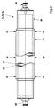
- FIGS. 2 and 3 show two embodiments of an inking roller F 1 , F 2 or F 3 according to the invention, which have an inner core 30 made of a relatively strong, rigid material such as. B. steel.
- the inner core 30 is preferably hollow to reduce the weight and can have pins 22 at both ends for the rotatable fastening of the inking roller F 1 , F 2 or F 3 .
- Hollow core 30 may include a suitable cooling mechanism, e.g. B. a coolant channel to avoid overheating of the inking roller F 1 , F 2 or F 3 during production printing.
- At least part of the axial length of the inner core 30 is an outer layer 21 made of an elastomer, e.g. B. Buna® rubber compound or another suitable compressible material.
- the elastomer from which the outer layer 21 is made is relatively hard, ie with a hardness of 50-100 Shore A, preferably between approximately 60 and 90 Shore A (durometer), in particular approximately 80 Shore A (durometer).
- the increased hardness of the outer layer 21 brings improved printing results because it causes a finer and more uniform ink splitting between the plate cylinder P and the inking rollers F 1 , F 2 or F 3 .
- the improved ink splitting leads to an improved deposition of the ink solids on the material web W after the transfer of the ink from the plate cylinder P to the blanket cylinder B L , which results in a high-quality print image with high optical density with less ink consumption than in conventional printing presses.
- the outer layer 21 of the inking roller F1, F2 or F3 Due to the increased hardness of the outer layer 21 of the inking roller F1, F2 or F3 according to the invention, it is stiffer and less flexible than conventional inking rollers, which means that when using a standard inking roller with a uniform outer diameter, the contact strip between the inking roller and the plate cylinder changes.
- the inking roller with the hard outer layer 21 as the last inking roller in the direction of rotation of the plate cylinder P, i.e. in the position of the inking roller F 3 in FIG. 1, and the other two inking rollers with a usual hardness, e.g. B. in the range of 27-35 Shore A. Improved printing results can be achieved if each of the inking rollers F 1 , F 2 and F 3 has a hard outer layer 21.
- an inking roller cooling system (not shown) e.g. B. in the form of coolant channels in the cavity inside the inking rollers F 1 , F 2 or F 3 .
Landscapes
- Inking, Control Or Cleaning Of Printing Machines (AREA)
- Printing Plates And Materials Therefor (AREA)
- Accessory Devices And Overall Control Thereof (AREA)
- Cleaning In Electrography (AREA)
- Rotary Presses (AREA)
Abstract
Description
- Fig. 1
- eine schematische Vorderansicht eines Farbwalzenzugs einer Offset-Druckmaschine gemäß der vorliegenden Erfindung;
- Fig. 2
- eine Vorderansicht sowie eine Innenansicht einer Farbauftragswalze gemäß einer ersten Ausführungsform der vorliegenden Erfindung;
- Fig. 3
- eine Vorderansicht sowie eine Innenansicht einer Farbauftragswalze gemäß einer zweiten Ausführungsform der vorliegenden Erfindung.
- 1
- Farbwalzenzug
- 2
- Feuchtwerk
- 10
- Farbkasten
- 11
- Druckplatte
- 12
- Gummituch
- 21
- Außenschicht
- 22
- Zapfen
- 30
- innerer Kern
- BL
- unterer Gummituchzylinder
- BU
- oberer Gummituchzylinder
- D
- Reiberwalze
- F1
- Farbauftragswalze
- F2
- Farbauftragswalze
- F3
- Farbauftragswalze
- I
- Farbkastenwalze
- L
- große Reiberwalze
- M
- Dosierwalze
- P
- Plattenzylinder
- S
- Schwingwalze
- V
- Heberwalze
- W
- Materialbahn
Claims (11)
- Farbwerk in einer Rotations-Offsetdruckmaschine mit einer Farbauftragswalze (F1, F2, F3), welche einen inneren Kern (30) und eine Außenschicht (21) aufweist,
dadurch gekennzeichnet
daß die Außenschicht (21) eine Härte im Bereich zwischen 50 Shore A und 100 Shore A aufweist. - Farbwerk nach Anspruch 1,
dadurch gekennzeichnet,
daß die Härte der Außenschicht (21) ca. zwischen 60 Shore A und 90 Shore A beträgt. - Farbwerk nach Anspruch 1 oder 2,
dadurch gekennzeichnet,
daß die Härte der Außenschicht (21) ca. 80 Shore A beträgt. - Farbwerk nach einem der vorhergehenden Ansprüche,
dadurch gekennzeichnet,
daß die Außenoberfläche der Außenschicht (21) entlang der axialen Länge der Außenschicht (21) eine konvexe Form aufweist. - Farbwerk nach einem der vorhergehenden Ansprüche,
dadurch gekennzeichnet,
daß die Außenschicht (21) ein Elastomer, z. B. Gummi, enthält. - Farbwerk nach einem der vorhergehenden Ansprüche,
dadurch gekennzeichnet,
daß der innere Kern (30) hohl ist. - Farbwerk nach einem der vorhergehenden Ansprüche,
dadurch gekennzeichnet,
daß eine Vielzahl von Farbauftragswalzen (F1, F2, F3) vorgesehen ist, welche jeweils eine Außenschicht (21) aufweisen, die eine Härte im Bereich zwischen 50 Shore A und 100 Shore A besitzt. - Farbwerk nach einem der Ansprüche 1 bis 6,
dadurch gekennzeichnet,
daß dieses eine weitere Farbauftragswalze (F1, F2) umfaßt, welche eine Außenschicht (21) aufweist, die eine geringere Härte, insbesondere im Bereich zwischen 20 Shore A und 40 Shore A besitzt. - Farbwerk nach Anspruch 8,
dadurch gekennzeichnet,
daß die Außenschicht (21) der weiteren Farbauftragswalze eine Härte im Bereich von 27 Shore A bis 35 Shore A aufweist. - Farbwerk nach einem der Ansprüche 8 oder 9,
dadurch gekennzeichnet,
daß die weitere Farbauftragswalze (F1, F2) der Farbauftragswalze (F3) in Drehrichtung des Plattenzylinders (P) gesehen vorgeordnet ist. - Druckmaschine mit einem Farbwerk nach einem der vorhergehenden Ansprüche.
Applications Claiming Priority (2)
| Application Number | Priority Date | Filing Date | Title |
|---|---|---|---|
| US09/131,564 US6098540A (en) | 1998-08-10 | 1998-08-10 | Apparatus and method for reducing mottling in printing presses |
| US131564 | 2002-04-23 |
Publications (4)
| Publication Number | Publication Date |
|---|---|
| EP0985530A2 true EP0985530A2 (de) | 2000-03-15 |
| EP0985530A3 EP0985530A3 (de) | 2000-10-04 |
| EP0985530B1 EP0985530B1 (de) | 2003-09-24 |
| EP0985530B2 EP0985530B2 (de) | 2009-01-14 |
Family
ID=22450006
Family Applications (1)
| Application Number | Title | Priority Date | Filing Date |
|---|---|---|---|
| EP99114183A Expired - Lifetime EP0985530B2 (de) | 1998-08-10 | 1999-07-22 | Farbwerk in einer Rotations-Offsetdruckmaschine mit einer Farbauftragswalze zur Verringerung des Pereffektes der Druckfarbe |
Country Status (5)
| Country | Link |
|---|---|
| US (1) | US6098540A (de) |
| EP (1) | EP0985530B2 (de) |
| JP (1) | JP2000052625A (de) |
| CN (1) | CN1131780C (de) |
| DE (2) | DE19934395B4 (de) |
Cited By (1)
| Publication number | Priority date | Publication date | Assignee | Title |
|---|---|---|---|---|
| DE102006011477A1 (de) * | 2006-03-13 | 2007-09-20 | Koenig & Bauer Aktiengesellschaft | Druckwerk mit einem geteilten Formzylinder |
Families Citing this family (11)
| Publication number | Priority date | Publication date | Assignee | Title |
|---|---|---|---|---|
| DE19911180C2 (de) * | 1999-03-12 | 2001-02-01 | Koenig & Bauer Ag | Druckwerk für eine Rotationsdruckmaschine |
| US7055428B2 (en) * | 2002-04-11 | 2006-06-06 | Koenig & Bauer Aktiengesellschaft | Characterization, determination of a characteristic number and selection of suitable dressings on cylinders of a printing press |
| WO2005118293A1 (en) * | 2004-05-21 | 2005-12-15 | Demaxz, L.L.C. | Apparatus for printing on substrates of timber or synthetic material |
| CN1939721B (zh) * | 2005-09-27 | 2010-12-15 | 海德堡印刷机械股份公司 | 用于对印刷机调节温度的方法 |
| DE102006015481B4 (de) * | 2006-01-04 | 2009-07-09 | Koenig & Bauer Aktiengesellschaft | Walze einer Druckmaschine |
| CN101045367A (zh) * | 2006-03-28 | 2007-10-03 | 海德堡印刷机械股份公司 | 网纹辊印刷装置 |
| DE102006015482B4 (de) * | 2006-04-03 | 2010-06-24 | Koenig & Bauer Aktiengesellschaft | Walze einer Druckmaschine |
| DE102006015490B4 (de) * | 2006-04-03 | 2009-11-12 | Koenig & Bauer Aktiengesellschaft | Rollendruckmaschine mit einem Filmfarbwerk |
| DE102006046521A1 (de) * | 2006-09-29 | 2008-04-03 | Man Roland Druckmaschinen Ag | Druckwerk einer Druckmaschine |
| US8726807B2 (en) * | 2007-06-04 | 2014-05-20 | Goss International Americas, Inc. | Smooth roller with low line load and methods |
| US20120279407A1 (en) * | 2011-05-06 | 2012-11-08 | Phoenix Machinery | Paper coater apparatus and process |
Family Cites Families (15)
| Publication number | Priority date | Publication date | Assignee | Title |
|---|---|---|---|---|
| CH355786A (de) * | 1958-01-24 | 1961-07-31 | Winkler Fallert & Co Maschf | Maschine zum Bedrucken von Papier und andern Stoffen in Bahnen mittels Tiefdruckwalzen |
| DE6910823U (de) * | 1969-03-17 | 1969-07-03 | Maschf Augsburg Nuernberg Ag | Filmwalze oder dgl. fuer farbwerke von rotationsdruckmaschinen |
| US3828674A (en) * | 1972-03-01 | 1974-08-13 | Houston Chronicle Publishing C | Printing press ink suppression apparatus |
| JPS5549295A (en) * | 1978-10-05 | 1980-04-09 | Toray Ind Inc | Ink roller for dry lithographic printing |
| DE3705194A1 (de) * | 1987-02-19 | 1988-09-01 | Frankenthal Ag Albert | Farbwerk |
| WO1989005732A1 (fr) * | 1987-12-21 | 1989-06-29 | Kinyosha Co., Ltd | Rouleau encreur pour presse d'imprimerie et fabrication dudit rouleau |
| DE8908243U1 (de) * | 1989-07-06 | 1989-08-17 | MAN Roland Druckmaschinen AG, 6050 Offenbach | Offsetdruckwerk |
| US5341733A (en) † | 1990-03-03 | 1994-08-30 | Albert Frankenthal Aktiengesellschaft | Short inking apparatus for a rotary press |
| JPH0422980A (ja) * | 1990-05-18 | 1992-01-27 | Canon Inc | 画像形成装置 |
| DE4103742C2 (de) * | 1991-02-07 | 1994-07-14 | Roland Man Druckmasch | Einstellbare Feuchtwerks- oder Farbwerkswalze |
| US5816150A (en) * | 1993-02-24 | 1998-10-06 | Sarda; Jean Lucien | Dampening units of offset printing presses |
| DE9310713U1 (de) * | 1993-07-17 | 1993-09-02 | Man Roland Druckmaschinen Ag, 63069 Offenbach | Farbauftragwalze |
| DE4436973C2 (de) † | 1993-12-21 | 2003-06-26 | Heidelberger Druckmasch Ag | Gummituch mit variierendem Profil und Verfahren zu seiner Herstellung |
| JP2951542B2 (ja) * | 1994-06-30 | 1999-09-20 | 日本ボールドウィン株式会社 | 冷却装置を有するローラ |
| DE29612105U1 (de) * | 1996-07-11 | 1996-08-22 | Man Roland Druckmaschinen Ag, 63069 Offenbach | Walze in einer Druckmaschine |
-
1998
- 1998-08-10 US US09/131,564 patent/US6098540A/en not_active Expired - Lifetime
-
1999
- 1999-07-22 DE DE19934395A patent/DE19934395B4/de not_active Expired - Fee Related
- 1999-07-22 DE DE59907097T patent/DE59907097D1/de not_active Expired - Lifetime
- 1999-07-22 EP EP99114183A patent/EP0985530B2/de not_active Expired - Lifetime
- 1999-07-26 CN CN99111013A patent/CN1131780C/zh not_active Expired - Fee Related
- 1999-08-09 JP JP11225255A patent/JP2000052625A/ja active Pending
Cited By (2)
| Publication number | Priority date | Publication date | Assignee | Title |
|---|---|---|---|---|
| DE102006011477A1 (de) * | 2006-03-13 | 2007-09-20 | Koenig & Bauer Aktiengesellschaft | Druckwerk mit einem geteilten Formzylinder |
| DE102006011477B4 (de) * | 2006-03-13 | 2007-12-27 | Koenig & Bauer Aktiengesellschaft | Druckwerk mit einem geteilten Formzylinder |
Also Published As
| Publication number | Publication date |
|---|---|
| EP0985530B2 (de) | 2009-01-14 |
| DE19934395A1 (de) | 2000-02-17 |
| EP0985530A3 (de) | 2000-10-04 |
| EP0985530B1 (de) | 2003-09-24 |
| CN1131780C (zh) | 2003-12-24 |
| CN1244462A (zh) | 2000-02-16 |
| US6098540A (en) | 2000-08-08 |
| JP2000052625A (ja) | 2000-02-22 |
| HK1023095A1 (en) | 2000-09-01 |
| DE19934395B4 (de) | 2012-11-08 |
| DE59907097D1 (de) | 2003-10-30 |
Similar Documents
| Publication | Publication Date | Title |
|---|---|---|
| EP0225509B1 (de) | Vorrichtung zum Bedrucken einer Bahn | |
| EP2703162B1 (de) | Verfahren und Vorrichtung zum Bedrucken von Bedruckstoff | |
| DE3237868A1 (de) | Druckwerk fuer den zeitungs- und zeitschriftendruck | |
| EP0061581A1 (de) | An einen Plattenzylinder einer Offset- oder Hochdruckmaschine anstellbarer Walzenstock | |
| EP0985530B1 (de) | Farbwerk in einer Rotations-Offsetdruckmaschine mit einer Farbauftragswalze zur Verringerung des Pereffektes der Druckfarbe | |
| DE8413874U1 (de) | Vorrichtung zum Befeuchten an lithographischen Druckpressen | |
| EP1457331B1 (de) | Kurzfarbwerk einer Rotationsdruckmaschine | |
| EP0116176B1 (de) | Farbwerk | |
| DE2259085A1 (de) | Farbwerk fuer flachdruckmaschinen | |
| EP0518892B1 (de) | Kurzfarbwerk für eine rollenrotationsdruckmaschine | |
| DE10044233A1 (de) | Verbindungsarmmechanismus zum einstellbaren Einstellen des Abstandes zwischen Plattenzylindern und Gummizylindern bei einer Rotationsoffsetdruckpresse | |
| EP0534160B1 (de) | Rotationsdruckmaschine | |
| EP1053887A2 (de) | Orloff-Mehrfarbendruckverfahren | |
| EP1627738A1 (de) | Druckeinheit und Farbwerk mit antriebsseitig getrennten, drehenden und changierenden Farbwerkwalzen | |
| DE69834752T2 (de) | Farbzuführrolle für drucker | |
| WO2005035249A1 (de) | Tiefdruckwerk | |
| EP0761432A1 (de) | Feuchtwerk für eine Offsetdruckmaschine | |
| EP0761431B1 (de) | Feuchtwerk für eine Offsetdruckmaschine | |
| DE10202785B4 (de) | Druckmaschine mit einem Farb- und Feuchtwerk | |
| DE19938870A1 (de) | Verfahren und Vorrichtung zum Aufbringen von Druckbildern auf Materialbahnen | |
| DE19628648C1 (de) | Zwischen Panoramadruck und Druck von vier Farben nebeneinander umstellbares Farbwerk | |
| DE69014670T2 (de) | Anordnung zum Auftragen der Farbe für Druckmaschinen. | |
| DE3130525A1 (de) | "rotationshochdruckmaschine" | |
| CH697158A5 (de) | Kurzfarbwerk. | |
| EP3569416A1 (de) | Rakel für eine siebdruckmaschine |
Legal Events
| Date | Code | Title | Description |
|---|---|---|---|
| PUAI | Public reference made under article 153(3) epc to a published international application that has entered the european phase |
Free format text: ORIGINAL CODE: 0009012 |
|
| AK | Designated contracting states |
Kind code of ref document: A2 Designated state(s): CH DE FR GB IT LI NL |
|
| AX | Request for extension of the european patent |
Free format text: AL;LT;LV;MK;RO;SI |
|
| PUAL | Search report despatched |
Free format text: ORIGINAL CODE: 0009013 |
|
| AK | Designated contracting states |
Kind code of ref document: A3 Designated state(s): AT BE CH CY DE DK ES FI FR GB GR IE IT LI LU MC NL PT SE |
|
| AX | Request for extension of the european patent |
Free format text: AL;LT;LV;MK;RO;SI |
|
| 17P | Request for examination filed |
Effective date: 20001016 |
|
| AKX | Designation fees paid |
Free format text: CH DE FR GB IT LI NL |
|
| 17Q | First examination report despatched |
Effective date: 20010608 |
|
| GRAH | Despatch of communication of intention to grant a patent |
Free format text: ORIGINAL CODE: EPIDOS IGRA |
|
| GRAS | Grant fee paid |
Free format text: ORIGINAL CODE: EPIDOSNIGR3 |
|
| GRAA | (expected) grant |
Free format text: ORIGINAL CODE: 0009210 |
|
| AK | Designated contracting states |
Kind code of ref document: B1 Designated state(s): CH DE FR GB IT LI NL |
|
| PG25 | Lapsed in a contracting state [announced via postgrant information from national office to epo] |
Ref country code: NL Free format text: LAPSE BECAUSE OF FAILURE TO SUBMIT A TRANSLATION OF THE DESCRIPTION OR TO PAY THE FEE WITHIN THE PRESCRIBED TIME-LIMIT Effective date: 20030924 Ref country code: IT Free format text: LAPSE BECAUSE OF FAILURE TO SUBMIT A TRANSLATION OF THE DESCRIPTION OR TO PAY THE FEE WITHIN THE PRESCRIBED TIME-LIMIT;WARNING: LAPSES OF ITALIAN PATENTS WITH EFFECTIVE DATE BEFORE 2007 MAY HAVE OCCURRED AT ANY TIME BEFORE 2007. THE CORRECT EFFECTIVE DATE MAY BE DIFFERENT FROM THE ONE RECORDED. Effective date: 20030924 |
|
| REG | Reference to a national code |
Ref country code: GB Ref legal event code: FG4D Free format text: NOT ENGLISH |
|
| REG | Reference to a national code |
Ref country code: CH Ref legal event code: EP |
|
| REF | Corresponds to: |
Ref document number: 59907097 Country of ref document: DE Date of ref document: 20031030 Kind code of ref document: P |
|
| GBT | Gb: translation of ep patent filed (gb section 77(6)(a)/1977) |
Effective date: 20031118 |
|
| NLV1 | Nl: lapsed or annulled due to failure to fulfill the requirements of art. 29p and 29m of the patents act | ||
| PLBI | Opposition filed |
Free format text: ORIGINAL CODE: 0009260 |
|
| ET | Fr: translation filed | ||
| PLAX | Notice of opposition and request to file observation + time limit sent |
Free format text: ORIGINAL CODE: EPIDOSNOBS2 |
|
| 26 | Opposition filed |
Opponent name: KBA KOENIG & BAUER AKTIENGESELLSCHAFT, -LIZEN Effective date: 20040623 |
|
| REG | Reference to a national code |
Ref country code: GB Ref legal event code: 732E |
|
| RAP2 | Party data changed (patent owner data changed or rights of a patent transferred) |
Owner name: GOSS INTERNATIONAL AMERICAS, INC. |
|
| PLAX | Notice of opposition and request to file observation + time limit sent |
Free format text: ORIGINAL CODE: EPIDOSNOBS2 |
|
| PLBB | Reply of patent proprietor to notice(s) of opposition received |
Free format text: ORIGINAL CODE: EPIDOSNOBS3 |
|
| REG | Reference to a national code |
Ref country code: CH Ref legal event code: NV Representative=s name: KIRKER & CIE SA |
|
| REG | Reference to a national code |
Ref country code: FR Ref legal event code: TP |
|
| PLCK | Communication despatched that opposition was rejected |
Free format text: ORIGINAL CODE: EPIDOSNREJ1 |
|
| APBP | Date of receipt of notice of appeal recorded |
Free format text: ORIGINAL CODE: EPIDOSNNOA2O |
|
| APAH | Appeal reference modified |
Free format text: ORIGINAL CODE: EPIDOSCREFNO |
|
| APBQ | Date of receipt of statement of grounds of appeal recorded |
Free format text: ORIGINAL CODE: EPIDOSNNOA3O |
|
| APBU | Appeal procedure closed |
Free format text: ORIGINAL CODE: EPIDOSNNOA9O |
|
| PUAH | Patent maintained in amended form |
Free format text: ORIGINAL CODE: 0009272 |
|
| STAA | Information on the status of an ep patent application or granted ep patent |
Free format text: STATUS: PATENT MAINTAINED AS AMENDED |
|
| 27A | Patent maintained in amended form |
Effective date: 20090114 |
|
| AK | Designated contracting states |
Kind code of ref document: B2 Designated state(s): CH DE FR GB IT LI NL |
|
| REG | Reference to a national code |
Ref country code: CH Ref legal event code: AEN Free format text: AUFRECHTERHALTUNG DES PATENTES IN GEAENDERTER FORM |
|
| PGFP | Annual fee paid to national office [announced via postgrant information from national office to epo] |
Ref country code: CH Payment date: 20100726 Year of fee payment: 12 |
|
| PGFP | Annual fee paid to national office [announced via postgrant information from national office to epo] |
Ref country code: GB Payment date: 20100726 Year of fee payment: 12 |
|
| REG | Reference to a national code |
Ref country code: CH Ref legal event code: PL |
|
| GBPC | Gb: european patent ceased through non-payment of renewal fee |
Effective date: 20110722 |
|
| PG25 | Lapsed in a contracting state [announced via postgrant information from national office to epo] |
Ref country code: LI Free format text: LAPSE BECAUSE OF NON-PAYMENT OF DUE FEES Effective date: 20110731 Ref country code: CH Free format text: LAPSE BECAUSE OF NON-PAYMENT OF DUE FEES Effective date: 20110731 |
|
| PG25 | Lapsed in a contracting state [announced via postgrant information from national office to epo] |
Ref country code: GB Free format text: LAPSE BECAUSE OF NON-PAYMENT OF DUE FEES Effective date: 20110722 |
|
| PGFP | Annual fee paid to national office [announced via postgrant information from national office to epo] |
Ref country code: FR Payment date: 20130717 Year of fee payment: 15 |
|
| REG | Reference to a national code |
Ref country code: FR Ref legal event code: ST Effective date: 20150331 |
|
| PG25 | Lapsed in a contracting state [announced via postgrant information from national office to epo] |
Ref country code: FR Free format text: LAPSE BECAUSE OF NON-PAYMENT OF DUE FEES Effective date: 20140731 |
|
| PGFP | Annual fee paid to national office [announced via postgrant information from national office to epo] |
Ref country code: DE Payment date: 20150729 Year of fee payment: 17 |
|
| REG | Reference to a national code |
Ref country code: DE Ref legal event code: R119 Ref document number: 59907097 Country of ref document: DE |
|
| PG25 | Lapsed in a contracting state [announced via postgrant information from national office to epo] |
Ref country code: DE Free format text: LAPSE BECAUSE OF NON-PAYMENT OF DUE FEES Effective date: 20170201 |