EP0982844B1 - Dispositif d'entrainement de moteur a courant continu sans balai - Google Patents
Dispositif d'entrainement de moteur a courant continu sans balai Download PDFInfo
- Publication number
- EP0982844B1 EP0982844B1 EP97935825A EP97935825A EP0982844B1 EP 0982844 B1 EP0982844 B1 EP 0982844B1 EP 97935825 A EP97935825 A EP 97935825A EP 97935825 A EP97935825 A EP 97935825A EP 0982844 B1 EP0982844 B1 EP 0982844B1
- Authority
- EP
- European Patent Office
- Prior art keywords
- phase
- voltage
- inverter
- command
- amplitude
- Prior art date
- Legal status (The legal status is an assumption and is not a legal conclusion. Google has not performed a legal analysis and makes no representation as to the accuracy of the status listed.)
- Expired - Lifetime
Links
Images


Classifications
-
- H—ELECTRICITY
- H02—GENERATION; CONVERSION OR DISTRIBUTION OF ELECTRIC POWER
- H02P—CONTROL OR REGULATION OF ELECTRIC MOTORS, ELECTRIC GENERATORS OR DYNAMO-ELECTRIC CONVERTERS; CONTROLLING TRANSFORMERS, REACTORS OR CHOKE COILS
- H02P6/00—Arrangements for controlling synchronous motors or other dynamo-electric motors using electronic commutation dependent on the rotor position; Electronic commutators therefor
- H02P6/10—Arrangements for controlling torque ripple, e.g. providing reduced torque ripple
Definitions
- the present invention relates to a synchronous motor driving method, compressor driving method, device for the methods, and brushless DC motor driving device. More particularly, the present invention relates to a synchronous motor driving method for driving a synchronous motor such as a brushless DC motor or the like using an inverter and a device for the method, and a compressor driving method for driving a compressor using the synchronous motor which is driven by such method or device and a device for the method, and a brushless DC motor driving device for driving a brushless DC motor using an inverter.
- a brushless DC motor is devotedly employed as a driving source which is easier in torque controlling than an AC motor due to a position detection mechanism which is previously provided to the brushless DC motor.
- a method for controlling a d-axis current to be 0 which gives no influence to motor torque generation that is the method for controlling a phase of current to be the same phase as a phase of a generation voltage due to a motor speed (the phase of current equals to 0), is known as a driving method which is free from lowering in efficiency, and is widely employed because of simplification in control.
- an embedded magnet arrangement brushless DC motor in which a rotor has permanent magnets which are embedded in an interior of the rotor, can simultaneously output two generation torques, that is a magnetic torque and a reluctance torque. Therefore, the embedded magnet arrangement brushless DC motor has a characteristic effect such that driving with higher efficiency than the surface magnet arrangement brushless DC motor is realized by determining distribution of the two torques to be adequate in response to a load torque so that the current is determined to have a minimum value and the total torque is determined to have a maximum value (hereinafter, referred to as "maximum torque control").
- the embedded magnet arrangement brushless DC motor has developed in application to an air-conditioner or the like in recent years which is required energy saving especially.
- a maximum torque control method for controlling an embedded magnet arrangement brushless DC motor is recited in "a controlling method which is adequate to an embedded magnetic arrangement PM motor (Umekomi-jishaku-kouzou-PM-mota ni tekishita seigyohou)", Motimoyo et al., Denki-gakkai Handoutai Denryoku Kenkyuukai Shiryou SPC-92-5. It is known that the maximum torque control is realized by controlling d - , and q-axis currents based upon a relational equation which is determined based upon electrical constants of a motor.
- a synchronous motor driving device comprising inverter control means controlling an inverter by multiplying a relative current amplitude with the product of an error output signal of an external control and a function of a global current compensation characteristic. The output of the multiplication is applied to the inverter to control the inverter.
- the present invention was made in view of the above problems.
- Minimizing in motor current is merely minimizing copper loses when the scope of the maximum torque controlling method is employed.
- a scope of maximum efficiency control is disclosed in "driving method of a brushless DC motor with high efficiency and with saving in energy (burashiresu DC mota no shou-enerugi- koukouritsu untenhou)", Morimoto et al., Dengakuron D, vol. 112-3, pp. 285 (Hei 4-3 ), but the problem in modeling errors exists which is similar to the problem (1) of the maximum torque control because the iron losses are determined to be constant.
- harmonic wave components of a load torque waveform a band of changing components of a current amplitude or current phase are easily limited to harmonic wave components which give great influence to vibration ⁇ for example, first order harmonic wave and second order harmonic wave for a one cylinder compressor which is an intermittent load: higher torque changing components give little influence to,a change in rotation and vibration due to the change in rotation, because the flywheel effect (effect of moment of inertia) is improved following a frequency ⁇ . Unnecessary electric power consumption is prevented due to the above operation, so that driving with higher efficiency is possible.
- a voltage may be employed instead of the current.
- the inverter is controlled by the inverter control means so as to superpose a varying amount upon an amplitude and a phase of a current waveform or voltage waveform when a torque control is performed for suppressing speed change within one rotation by a synchronous motor controlled with an inverter which motor drives a load having a cyclic torque change. Therefore, a torque control is realized which drives the load having the cyclic intermittence under a maximum efficiency condition (or in a higher efficiency condition) using a practical arrangement so that the vibration in a low speed is decreased.
- means for controlling a varying amount in phase based upon an output of a torque control section and for controlling a varying amount in amplitude based upon a detection amount corresponding to efficiency are employed as the inverter control means. Therefore, control including iron losses is realized, the iron losses not being considered in the maximum torque controlling method. Also, operations similar to those of claim 1 are performed.
- the first center point voltage is obtained using the resistances, each having one end which is connected to an output terminal of each phase of the inverter and another end which is connected to one another
- the second center point voltage is obtained using the stator winding each of which of each phase of the synchronous motor is connected at one end to one another
- the difference between the first center point voltage and the second center point voltage is integrated by the integration means so that the integration signal is obtained
- the magnetic pole position of a rotor of the synchronous motor is detected by the magnetic pole position detection means based upon the integration signal. Therefore, providing a Hall element, encoder or the 1-ike is not required for detecting the magnetic pole position. Further, operations similar to those of one of claims 1 to 8 are performed.
- the one cylinder compressor is driven using the synchronous motor which is driven by the synchronous motor driving device according to one of the claims 1 to 9.
- the voltage equation of the, synchronous motor is represented as the formula (2)
- the generation torque is given as the equation (3) using d-, and q-axis currents.
- the d-axis is an axis which represents a direction of magnetic flux which is generated by permanent magnets
- the q-axis is an axis which is shifted by 90 degrees electrically from the d-axis.
- voltages applied to the synchronous motor are represented as the formula (4) which is obtained by transforming the formula (1).
- the applied voltages of the synchronous motor are calculated using the formula (2) and formula (4).
- p represents a number of pairs of magnetic poles
- R represents a winding resistance
- Ld represents self-inductances which are transformed to the d-, q-coordinates system
- Ke represents a constant of speed electromotive voltage.
- ⁇ represents an electric angle.
- the changing component in phase becomes smaller because the inductance is smaller than the inductance of an embedded magnet arrangement brushless DC motor. Therefore, the efficiency improvement effect of the torque control in which the voltage amplitude and voltage phase are changed, is smaller than that of the embedded magnet arrangement brushless DC motor. But, efficiency improvement effect of the torque control is obtained by employing the surface magnet arrangement brushless DC motor and by changing the voltage amplitude and voltage phase.
- the distribution of the d-, and q- axis currents should be adjusted suitably responding to the size of the torque when the torque control is performed for minimizing the motor current.
- a reluctance motor (a motor driven by reluctance torque only) which is one species of synchronous motor
- the current phase of 45 degrees is the maximum torque control condition by determining the speed electromotive voltage constant to be 0 in the equation (6).
- the inductance L is determined to be great for obtaining a reluctance torque, so that the changing component in voltage phase should be determined to be great. Therefore, efficiency improvement effect which is similar to that of the embedded magnet arrangement brushless DC motor is realized by performing torque control by changing the voltage amplitude and voltage phase.
- the amplitude and phase are obtained as illustrated in Fig. 3 .
- the current amplitude and current phase should be changed for generating a motor torque which is coincident to the intermittent load under the condition that the motor current is minimized.
- the torque control with minimized motor current is realized by employing the simple control which adjusts the size and phase of the changing components in the current amplitude and in the current phase. Therefore, complicated operations using many modeling constants are not required, and a man-hour for measuring many modeling constants under each condition for considering the influence of temperature rising and magnetic saturation is not required.
- the applied voltages are obtained as illustrated in Fig. 4 . It is understood that the amplitude and phase in the applied voltages should be changed in synchronism with the intermittence in the load torque, as is similar as of the motor currents.
- dashed lines in Fig. 3 and Fig 4 represent an average value of the waveform.
- the first center point voltage is obtained using resistances, each having one end which is connected to an output terminal of each phase of the inverter and another end which is connected to one another
- the second center point voltage is obtained using each stator winding of each phase of the brushless DC motor which is connected at one end to one another
- the difference between the first center point voltage and the second center point voltage is integrated by the integration means so that the integration signal is obtained
- the magnetic pole position of a rotor of the brushless DC motor is detected by the magnetic pole position detection means based upon the integration signal
- inverter control means for controlling an inverter so that the changing voltage which is advanced with respect to the phase of the load torque is superposed upon the average value voltage command in synchronism with intermittence of the load torque for applying to the brushless DC motor by the inverter control means using the inverter.
- the change in peak value of the integration signal are suppressed by the peak value changing suppression means.
- the inverter interval is divided by the,division means, and the level of the integration signal is judged at every divided interval by the judgment means whether the level is great or small. And, the inverter voltage phase is retarded responding to the judgment result representing that the level of the integration signal is great and the inverter voltage phase is advanced responding to the judgment result representing that the level of the integration signal is small by the inverter voltage phase control means.
- the first center point voltage is obtained using resistances, each having one end which is connected to an output terminal of each phase of the inverter and, another end which is connected to one another
- the second center point voltage is obtained using each stator winding of each phase of the brushless DC motor which is connected at one end to one another
- the difference between the first center point voltages and the second center point voltage is integrated by the integration means so that the integration signal is obtained
- the magnetic pole position of the rotor of the brushless DC motor is detected by the magnetic pole position detection means based upon the integration signal
- the changing phase which is advanced with respect to the phase of the load torque is superposed upon the average value phase command in synchronism with intermittence of the load torque for applying to the brushless DC motor by the inverter control means using the inverter.
- changes in peak value of the integration signal are suppressed by the peak value changing suppression means.
- the inverter interval is divided by the division means, and the-integration signal is judged whether its level is great or small for every divided interval by the judgment means. And, the inverter voltage amplitude is increased responding to the judgment result representing that the level of the integration signal is great and the inverter voltage amplitude is decreased responding to the judgment result representing that the level of the integration signal is small by the inverter voltage amplitude control means.
- Fig. 5 is a block diagram illustrating an embodiment of a synchronous motor driving device according to the present invention.
- This synchronous motor driving device includes a speed deviation calculation section 1 for calculating a deviation between a speed command ⁇ * and a motor speed ⁇ , a speed controlling section 2 for outputting an average value command of a current amplitude by inputting the calculated deviation and by carrying out a predetermined operation (for example, PI operation (proprtional and integral operation) ⁇ , a current amplitude command output section 3 for adding the average value command of the current amplitude and a changing component of the current amplitude at every rotation position output from a torque control section 10 (described later) and for outputting a current amplitude command, a three phase alternate current calculating section 4 for inputting the current amplitude command and a current phase command output from a current phase command output section 11 (described later) and for outputting a three phase alternate current command based upon a formula (8) for example, a current-fed inverter 5 for inputting the three phase alternate current command, a synchronous motor 6 to which is applied the output of the current-fed inverter 5,
- the rotor position detecting section 7 is exemplified as a rotation position sensor such as an encoder and a counter circuitry for the output therefrom, a position detecting circuitry for performing filtering to a motor terminal voltage, a circuitry for carrying out position calculation from electrical parameters of a motor and the like.
- the synchronous motor 6 is exemplified as a surface magnet arrangement brushless DC motor, an embedded magnet arrangement brushless DC motor, a reluctance motor and the like.
- Fig. 6 is a flowchart useful in understanding an operation of the synchronous motor driving device illustrated in Fig. 5 .
- step SP1 a rotor position (position angle) ⁇ is input, in step SP2, a rotation speed (motor speed) ⁇ is calculated from the rotor position , in step SP3, a difference between a real speeds ⁇ and a speed command w ⁇ is applied a PI operation (proportional, integral operation) and an average current amplitude command is obtained, in step SP4, the torque control operation is carried out by inputting the real speed ⁇ and the rotor position ⁇ so that a changing component of the current amplitude is obtained from a changing component of the real speed, in step SP5, the average current amplitude command and the changing component of the current amplitude are added so as to obtain and memorize an amplitude command, in step SP6, the changing component of the current amplitude is multiplied with a coefficient, then is shifted so as to obtain a changing component of a current phase (wherein, the coefficient, and a shifting amount are determined experimentally, for example), in step SP7, an average phase command ⁇ ⁇ from the exterior and
- Fig. 7 is a block diagram illustrating another embodiment of the synchronous motor driving device according to the present invention.
- This synchronous motor driving device is different from the synchronous motor driving device illustrated in Fig. 5 in that a current, deviation calculating section 5d for calculating a deviation between the three phase alternate current command and a winding current detection value which is output from a winding current detecting section 5c (describes later), a current control section 5a for inputting the calculated deviation and for carrying out current control so as to transform a current command into a voltage command, a voltage-fed inverter 5b for inputting the transformed voltage command, and the winding current detecting section 5c for detecting a winding current of a synchronous motor 6 (described later) are employed instead of the current-fed inverter 5.
- the other arrangement sections are similar to those of the synchronous motor driving device illustrated in Fig. 5 .
- the current control section 5a, voltage-fed inverter 5b, winding current detecting section 5c and current deviation calculating section 5d constitute a current-fed inverter.
- Fig. 8 is a flowchart useful in understanding an operation of the synchronous motor driving device illustrated in Fig. 7 .
- step SP1 a rotor position (position angle) ⁇ is input, in step SP2, a rotation speed (motor speed) ⁇ is calculated from the rotor position , in step SP3, a difference between a real speed and a speed command ⁇ ⁇ is applied,a PI operation (proportional, integral operation) so as to obtain an average current amplitude command, in step SP4, the torque control operation is carried out by inputting the real speed ⁇ and the rotor position so as to obtain a changing component in current amplitude from a real speed changing component; in step SP5, the average current amplitude command and the changing component in current amplitude are added so as to obtain and memorize an amplitude command, in step SP6, the changing component in current amplitude is multiplied by a coefficient and then shifted so as to obtain a changing component in current phase (wherein, the coefficient, shifting amount are determined experimentally, for example), in step SP7, an average phase command ⁇ ⁇ and the changing component in current phase are added so as to obtain and memorize a
- synchronous motor driving device illustrated in Fig. 7 can be simplified in its arrangement in its entirety, because the device employs a voltage-fed inverter which has a main circuitry arrangement which is more simple than that of a current-fed inverter.
- Fig. 9 is a block diagram illustrating a synchronous motor driving device of a further embodiment according to the present invention.
- This synchronous motor driving device includes a speed deviation calculating section 21 for calculating a deviation between a speed command ⁇ ⁇ and a motor speed ⁇ , a speed control section 22 for outputting an average value command of a voltage amplitude by inputting the calculated deviation and by carrying out a predetermined operation (for-example, a PI operation), a voltage amplitude command output section 23 for adding the average value command of the voltage amplitude and a changing, component of the voltage amplitude at every rotation position output from a torque controlling section 30 (described later), and for outputting a voltage amplitude command, a three phase alternate current calculating section 24 for inputting the voltage amplitude command and a voltage phase command output from a voltage phase command output section 31 (described later) and for outputting three phase alternate current command based upon a formula (9) for example, a voltage-fed inverter 25 for inputting the three phase alternate current command, a synchronous motor 6 to which is applied the output of the voltage-fed inverter 25, a rotor
- the rotor position detection section 27 is exemplified as a rotation position sensor such as an encoder and a counter circuitry for the output therefrom, a position detecting circuitry for performing filtering to a motor terminal voltage, a circuitry for carrying out position calculation from electrical parameters of a motor and the like.
- Fig. 10 is a flowchart useful in understanding an operation of the synchronous motor driving device illustrated in Fig. 9 .
- step SP1 a rotor position (position angle) is input, in step SP2, a rotation speed (motor speedy) ⁇ is calculated from the rotor position ⁇ , in step SP3, a difference between a real speed and a speed command ⁇ ⁇ is applied a PI operation (proportional, integral operation) so as to obtain an average voltage amplitude command, in step SP4, torque control-operation is carried out by inputting the real speed ⁇ and the rotor position so as to obtain a changing component in voltage amplitude from a real speed changing component, in step SP5, the average voltage amplitude command and the changing component in voltage amplitude are added so as to obtain and memorize an amplitude command, in step SP6, the changing component in voltage amplitude is multiplied by a coefficient and then shifted so as to obtain a changing component in voltage phase (wherein, the coefficient, shifting amount are determined experimentally, for example), in step SP7, an average phase command ⁇ ⁇ and the changing component in voltage phase are added so as to obtain and memorize
- Fig. 11 is a block diagram illustrating a synchronous motor driving device of yet another embodiment according to the present invention.
- This synchronous motor driving device includes a speed deviation calculating section 41 for calculating a deviation between a speed command ⁇ ⁇ and a motor speed ⁇ , a speed control section 42 for outputting an average value command of a voltage phase by inputting the calculated deviation and by carrying out a predetermined operation (for example, a PI operation), a voltage phase command output section 43 for,adding the average value command of the voltage phase and a changing component of the voltage phase at every rotation position output from a torque control section 50 (described later) and for outputting a voltage phase command, a three phase alternate current calculating section 44 for inputting the voltage phase command and a voltage amplitude command output from a voltage amplitude command output section 51 (described later) and for outputting a three phase alternate current command based upon a formula (9) for example, a voltage-fed inverter 45 for inputting the three phase alternate current command, a synchronous motor 6 to which is applied the output of the voltage-fed inverter 45, a rotor position detecting section 47 for
- the rotor position detecting section 47 is exemplified as a rotational position sensor such as an encoder and a counter circuitry for the output therefrom, a position detecting circuitry for performing filtering to a motor terminal voltage, a circuitry for carrying out position calculation from electrical parameters of a motor and the like.
- Fig. 12 is a flowchart useful in understanding an operation of the synchronous motor driving device illustrated in Fig. 11 .
- step SP1 a rotor position (position angle) ⁇ is input, in step SP2, a rotation speed (motor speed) ⁇ is calculated from the rotor position ⁇ , in step SP3, a difference between a real speed and a speed command ⁇ ⁇ is applied a PI operation (proportional, integral operation) so as to obtain an average voltage phase command, in step SP4, torque control operation is carried out by inputting the real speed ⁇ and the rotor position ⁇ so as to obtain a changing component in voltage phase from a real speed changing component, in step SP5, the average voltage phase command and the changing component in voltage phase are added so as to obtain and memorize a phase command, in step SP6, the changing component in voltage phase is multiplied by a coefficient and is then shifted so as to obtain a changing component in voltage amplitude (wherein, the coefficient, shifting amount are determined experimentally, for example), in step SP7, an average amplitude command Vm* and the changing component in voltage amplitude are added so as to obtain and memorize an amplitude
- Fig. 13 is a block diagram illustrating a synchronous motor driving device of a yet further embodiment according to the present invention.
- This synchronous motor driving device includes a speed deviation calculating section 61 for calculating a deviation between a speed command ⁇ ⁇ and a motor, speed ⁇ , a speed control section 62 for outputting an average value command of a voltage amplitude by inputting the calculated deviation and by carrying out a predetermined operation (for example, a PI operation), a voltage amplitude command output section 63 for adding the average value command of the voltage amplitude and a changing component of the voltage amplitude at every rotation position output from a torque control section 70 (described later) and for outputting a voltage amplitude command, a three phase alternate current calculating section 64 for inputting the voltage amplitude command and a voltage phase command output from a voltage phase command output section 71 (described later) and for outputting a three phase alternate current command based upon a formula (9) for example, a voltage-fed inverter 65 for inputting the three phase alternate current command, a synchronous motor 6 to which is applied the output of the voltage-fed inverter 65,
- the rotor position detecting section 67 is exemplified as a rotation position sensor such as an encoder and a counter circuitry for the output therefrom, a position detecting circuitry for performing filtering to a motor_terminal voltage,-a circuitry for carrying out position calculation from electrical parameters of a motor and the like.
- the current control is carried out by adding a winding current detecting section and a current controlling section. Also, it is possible that a current-fed inverter is employed instead of the voltage-fed inverter.
- Fig. 14 is a flowchart useful in understanding an operation of the synchronous motor driving device illustrated in Fig. 13 .
- step SP1 a rotor position (position angle) ⁇ is input, in step SP2, a rotation speed (motor speed) ⁇ is calculated from the rotor position ⁇ , in-step SP3, a difference between a real speed ⁇ and a speed command ⁇ ⁇ is applied a PI operation (proportional, integral operation) so as to obtain an average voltage amplitude command, in step SP4, the torque control operation is carried out by inputting the real speed ⁇ and the rotor position ⁇ so as to obtain a changing component in voltage amplitude from a real speed changing component, in step SP5, the average voltage amplitude command and the changing component in voltage amplitude are added so as to obtain and memorize an amplitude command, in step SP6, the changing component in voltage phase is applied for controlling and operating in response to a size of an inverter input current (for minimizing the inverter input current), in step SP7, an average phase command ⁇ ⁇ and the changing component in voltage phase are added so as to obtain and memorize a phase command, in step
- control for minimizing an inverter input power may be carried out by adding voltage detection and by calculating an inverter input power, instead of controlling and operating of the changing component in voltage phase in response to the size of the inverter input current.
- Fig. 15 is a block diagram illustrating a synchronous motor driving device of a further embodiment according to the present invention.
- This synchronous motor driving device includes a speed deviation calculating section 81 for calculating a deviation between a speed command ⁇ ⁇ and a motor speed ⁇ , a speed control section 82 for outputting an average value command of a voltage phase by inputting the calculated deviation and by carrying out a predetermined operation (for example, a_PI operation), a voltage phase command output section 83 for adding the average value command of the voltage phase and a changing component of the voltage phase at every rotation position output from a torque control section 90 (described later) and for outputting a voltage phase command, a three phase alternate current calculation section 84 for inputting the voltage phase command and a voltage amplitude command output from a voltage amplitude command output section 91 (described later) and for outputting a three phase alternate current command based upon a formula (9) for example, a voltage-fed inverter 85 for inputting the three phase alternate current command, a synchronous motor 6 to which is applied the output of the voltage-fed inverter 85, a rotor position detecting section
- a speed calculating section 89 for inputting the position angle ⁇ and for calculating and outputting a motor speed therefrom
- the torque control section 90 for inputting the motor speed ⁇ and position angle , for carrying out torque control operation, and for outputting a changing component of the voltage phase at every rotation position
- an amplitude control section 88 for inputting an inverter input current detected by an inverter input current detecting section 92 (described later), for carrying out an amplitude control operation, and for calculating and outputting a changing component command of a voltage amplitude
- the voltage amplitude command output section 91 for adding an average amplitude command ⁇ ⁇ which is obtained by a manner which is known in the past and the changing component command and for calculating and outputting the voltage amplitude command therefrom
- the inverter input current detecting section 92 for detecting the inverter input current (one species of detection quantities which are related to efficiency) which is supplied to the voltage-fed inverter 85 from a commercial power source 93.
- the rotor position detecting section 87 is exemplified as a rotation position sensor such as an encoder and a counter circuitry for the output therefrom, a position detecting circuitry for performing filtering to a motor terminal voltage, circuitry for carrying out position calculation from electrical parameters of a motor and the like.
- current control is carried out by adding a winding current detecting section and a current control section.
- a current-fed inverter is employed instead of the voltage-fed inverter.
- a control for minimizing an inverter input power may be carried out by adding detection of voltage and by calculating an inverter input power, instead of controlling and operating of the changing component in voltage phase in response to the size of the inverter input current.
- Fig. 16 is a chart illustrating change in load torque corresponding to the rotation angle of one cylinder compressor
- Fig. 17 is a chart illustrating the frequency distribution of the load torque.
- an actual intermittent load includes many frequency components.
- a torque control is carried out for completely compensating the frequency' components and for suppressing speed change which is a cause of vibration, a disadvantage arises in that an effective value and a peak value of a motor current are increased.
- Fig. 18 is a block diagram illustrating a synchronous motor driving device of a yet further embodiment according to the present invention.
- This synchronous motor driving device includes a speed deviation calculating section 101 for calculating a deviation between a speed command ⁇ ⁇ and a motor speed ⁇ , a speed control section 102 for outputting an average value command of a voltage amplitude by inputting the calculated deviation and by carrying out a predetermined operation (for example, a PI operation), a voltage amplitude command output section 103 for adding the average value command of the voltage amplitude and a changing component of the voltage amplitude at every rotation position output from a voltage amplitude changing component output section 113 (described later) and for outputting a voltage amplitude command, a three phase alternate current calculating section 104 for inputting the voltage amplitude command and a voltage phase command output from a voltage phase command output section 111 (described later) and for outputting a three phase alternate current command based upon a formula (9) for example, a voltage-fed inverter 105 for inputting the three phase alternate current command, a synchronous motor 6 to'which is applied the output of the voltage-
- the rotor position detecting section 107 is exemplified as a rotation position sensor such as an encoder and a counter circuitry for the output therefrom, a position detection circuitry for performing a filtering to a motor terminal voltage, a circuitry for carrying out position calculation from electrical parameters of a motor and the like.
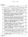
- Fig. 19 is a flowchart useful in understanding an operation of the synchronous motor driving device illustrated in Fig. 18 .
- step SP1 a rotor position (position angle) ⁇ is input, in step SP2, a rotation speed (motor speed) ⁇ is calculated from the rotor position ⁇ , in step SP3, a difference between a real speed ⁇ and a speed command ⁇ ⁇ is applied a PI operation (proportional, integral operation) so as to obtain an average voltage amplitude command, in step SP4, a torque control operation is carried out by inputting the real speed ⁇ and the rotor position so as to obtain a changing component in voltage amplitude from a real speed changing component, in step SP5, for adding a third order harmonic of phase for reducing a peak to the changing component of voltage amplitude so as to calculate a new changing component of voltage amplitude, in step SP6, the average voltage amplitude command and the new changing component in voltage amplitude are added so as to obtain and memorize an amplitude command, in step SP7, the new changing component in voltage phase is multiplied by a coefficient, the product is then shifted, so that a changing component
- a current control may be carried out by adding a winding current detecting section and a current control section.
- the third order harmonic is superposed upon the voltage command, but the third order harmonic may be superposed upon the current command.
- current-fed inverter or current control type inverter which comprises a voltage-fed inverter, a winding current detecting section in addition, and a current control section in addition, for performing current controlling.
- a superposing degree of the third order harmonic is determined based upon the specification of the synchronous motor driving system.
- Figs. 20 are charts illustrating torque waveforms ⁇ refer to Fig.. 20 (A) ⁇ , current amplitude waveforms ⁇ refer to Fig. 20 (B) ⁇ , and current phase waveforms ⁇ refer to Fig. 20 (C) ⁇ when the third order harmonic of the current waveform is superposed so that the third order harmonic of about 10 % with respect to the fundamental wave of torque is superposed upon the torque waveform.
- a represents a waveform which is obtained by superposing the third order harmonic
- b represents a waveform which is not superposed the third order harmonic
- c represents an average value.
- a peak of the current amplitude (a peak of the motor current) is suppressed by superposing the third order harmonic. Therefore, driving with a shifted operation point caused by a limitation in the current capacity of an inverter element is not needed, and a control of the synchronous motor driving device, and synchronous motor driving method illustrated in Fig. 5 to Fig. 15 is realized in wider range.
- the third order harmonic may not be included in the load torque, or the third order harmonic may increase speed change in the case where the amplitude relationship or the phase relationship is different from the above relationship. But, this does not raise a problem in practice and this has the above advantage so that it is preferable that the superposing of then third order harmonic is applied to a synchronous motor driving device and a synchronous motor driving method, by taking the flywheel effects being great and the vibration preventing design which is applied at the installing time into consideration.
- Fig. 21 is a block diagram illustrating a synchronous motor driving device of a further embodiment according to the present invention.
- each serial connection circuit is connected in parallel to one another between terminals of a direct current power source 120 so that a voltage-fed inverter 121 is constructed, each serial connection circuit being constructed by connecting two switching transistors in series. Further, a diode for protection is connected in parallel to each switching transistor.
- Three resistances 122u, 122v and 122w which are connected in a Y-connection arrangement, and stator windings 6u, 6v and 6w of a synchronous motor 6 which are connected in a Y-connection arrangement, are connected to a center point of each serial connection circuitry. Further, 6a represents a rotor.
- a first center point voltage VN obtained at a center point of the resistances 122u, 122v and 122w is supplied to a non-reverse input terminal of an operation amplifier 123a
- a second center point voltage VM obtained at a center point of the stator windings 6u, 6v and 6w is supplied to a reverse input terminal of the operation amplifier 123a through a resistance 123b.
- a resistance 123c is connected between the reverse input terminal and an output terminal of the operation amplifier 123a. Therefore, a difference voltage VNM corresponding to a difference between the first center point voltage VN and the second center point voltage VM is obtained at the output terminal of the operation amplifier 123a.
- the difference voltage VNM is supplied to an integration circuitry in which a resistance 124a and a condenser 124b are connected in series to one another.
- An integration signal ⁇ VNOdt obtained at a center point of the resistance 124a and the condenser 124b is supplied to a non-reverse input terminal of an operation amplifier 125, and a reverse input terminal of the operation amplifier 125 is connected to a ground, so that a zero-cross comparator is constituted.
- An output signal from the zero-cross comparator is supplied to a micro-processor 126 as a position signal (magnetic pole detection signal).
- the integration signal ⁇ SVNOdt is supplied to an integration signal level detection circuitry 127.
- a detection signal from the integration signal level detection circuitry 127 is supplied to the micro-processor 126.
- a speed command and a speed changing command are also supplied to the micro-processor 126.
- the micro-processor 126 outputs signals for controlling the inverter 121 through a base driving circuitry 128.
- Fig. 22 is a block diagram illustrating an arrangement of the micro-processor 126.
- This micro-processor 126 includes an interval measurement timer 131 for carrying out a stop, reset and restart by an interruption processing 1 due to receiving of the position signal, a position signal interval calculating section 132 for calculating an interval of the position signal by inputting a timer value of the interval measurement timer 131 at the stopping timing, a speed calculating section 133 for carrying out speed operation by inputting the interval of the position signal output from the position signal interval calculating section 132 and for calculating and outputting a present speed, a deviation calculating section 134 for calculating a difference between a speed command given from the exterior and the present speed output from the speed calculating section 133 and for outputting this difference as a speed change, a changeover signal calculating section 135 for calculating and outputting a changeover signal by inputting the speed change output from the deviation calculating section 134 and a speed change command given from the exterior, a first order component compensation model calculating section 136 for calculating and outputting a first order component compensation model by inputting the speed change output from the deviation
- the primary component compensation model calculating section 136 carries out the compensation operation using gains which are 0 for components other than the first order component. Therefore, no problems arise even when a speed change is employed as an input of the first order component compensation model calculating section 136. That is the speed command becomes constant (direct current) under a steady condition, and the output from the first order component compensation model calculating section 136 is zero even when a direct current (or a signal which has a frequency different from a frequency of an output signal from a signal model) is input to the first order component compensation model calculating section 136.
- Fig. 23 is a schematic diagram illustrating a control model of a system in which a compressor is driven using a synchronous motor which is driven by the synchronous motor driving device illustrated in Fig. 21 .
- This control model includes a subtraction section 201 for calculating a difference between the speed command and the rotation speed of the synchronous motor 6, a PI control section 202 for carrying out proportional control and integral control (PI control) by inputting the difference output from the subtraction section 201 and for outputting a proportional control result and an integral control result therefrom, a speed change average value calculating section 203, for calculating a size ⁇ of an average of the speed change during N-rotations (N is a natural number) by inputting the difference output from the subtraction section 201, a changeover section 204 for outputting 0 or 1 by inputting the size ⁇ of an average of the speed change output from the speed change average value calculating section 203, a multiplication section 205 for multiplying the rotation speed of the synchronous motor 6 and the output from the changeover section 204 and for outputting a multiplication result, a variable arrangement first order component compensation section 206 for carrying out first order component compensation by inputting the multiplication result output from the multiplication section 205 and for outputting
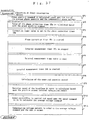
- Fig. 24 to Fig. 26 are flowcharts useful in understanding the operation of the micro-processor 126. Wherein, Fig. 24 explains the interruption processing 1, Fig. 25 explains the interruption processing 2, and Fig. 26 explains the interruption processing 3.
- step SP1 a value for the phase correction timer 140 is calculated from the phase amount command, in step SP2, the phase correction timer value is set in the phase correction timer 140, in step SP3, the phase correction timer 140 is started, in step SP4, the interval measurement timer 131 is stopped, in step SP5, a value of the interval measurement timer 131 is read, in step SP6, the value of the interval measurement timer 131 is reset, then the interval measurement timer 131 is started for the next interval measurement.
- step SP7 an interval of the position signal is calculated, in step SP8, a motor rotation speed is calculated from the calculation result of the interval of the position signal, in step SP9, speed change is calculated based upon the motor rotation speed and the speed command, in step SP10, the PI operation is carried out to the speed change, and the average voltage amplitude command is calculated, in step SP11, the average value of the size of the speed change is calculated and the changeover signal is output based upon the obtained average value, in step SP12, a compensation voltage amplitude is calculated based upon the speed change and the changeover signal, in step Sup13, the compensation voltage amplitude is added to the average voltage amplitude, in step SP14, the delay processing is carried out ⁇ for example, the compensation voltage amplitude is memorized, and the compensation voltage amplitude is read out which is prior to M samples (wherein, M is a positive integer) ⁇ , in step SP15, a compensation phase is calculated by multiplying a predetermined coefficient by the coefficient device 146, in step SP16, the compensation
- step SP1 an inverter mode is advanced by 1 step, in step SP2, a voltage pattern corresponding to the advanced inverter mode is output, then the operation is returned to an original processing.
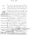
- Figs. 27 are charts illustrating signal waveforms of each section of the synchronous motor driving device which is illustrated in Fig. 21 and Fig. 22 .
- the difference voltage VNM is obtained as illustrated in Fig. 27 (A)
- the integration signal VN0dt is obtained as illustrated in Fig. 27(B)
- the position signal is obtained as illustrated in Fig. 27 (C) .
- the phase correction timer 140 starts as illustrated in Fig. 27 (D) ⁇ refer to starting points of arrows illustrated in Fig. 27(D) ⁇ by the interruption processing 1 based upon the position signal. And, the conduction width control timer 141 starts as illustrated in Fig. 27 (E) ⁇ refer to starting points of arrows illustrated in Fig. 27(E) ⁇ at every output of the count-over signal ⁇ refer to ending points of arrows illustrated in Fig. 27(D) ⁇ from the phase correction timer 140 which is controlled the timer value which is set based upon the phase amount command as illustrated in Fig. 27 (M) .
- the inverter mode is advanced by every 1 step as illustrated in Fig. 27 (N) , and ON-OFF conditions of the switching transistors 121ul, 121u2, 121v1, 121v2, 121w1, 121w2 of the inverter circuitry 121 are changed corresponding to the inverter mode as illustrated in Fig. 27(F) to Fig. 27(K) , at every output of the count-over signal from the phase correction timer 140 ⁇ refer to ending points of arrows illustrated in Fig. 27(D) ⁇ and at every output of the count-over signal from the conduction width control timer 141 ⁇ refer to ending points of arrows illustrated in Fig. 27(E) ⁇ .
- each switching transistor is applied chopper control by the PWM section 144 based upon the inverter output voltage illustrated in Fig. 27(L) .
- the dashed line illustrated in Fig. 27 (L) represents the output (average voltage) from the PI operation section 137, and the solid line illustrated in Fig. 27(L) represents the output (compensation voltage) from the first order component compensation model calculating section 136.
- phase control becomes a control system with 1 sample delay in connection to the timer processing.
- Figs. 28 are charts illustrating a line voltage amplitude waveform ⁇ refer to Fig. 28 (A) ⁇ , a voltage phase waveform (refer to Fig. 28 (B) ⁇ , a phase current waveform ⁇ refer to Fig. 28 (C) ⁇ , and an inverter DC current waveform ⁇ refer to Fig. 28(D) ⁇ when a compressor is driven by controlling the voltage phase and the voltage amplitude, each being relative to one another, based upon the scope of the maximum torque control.
- Figs. 29 are charts illustrating a line voltage amplitude waveform ⁇ refer to Fig. 29 (A) ⁇ , a voltage phase waveform ⁇ refer to Fig.
- the driving condition is as follows; low pressure: 5 kg/cm 2 , high pressure: 13 kg/ cm 2 , rotation number: 20 r. p. s..
- Fig. 30 is a block diagram illustrating an arrangement of a micro-processor which is a main section of a synchronous motor driving device of a further embodiment according to the present invention. Further, arrangement other than the micro-processor is the same as the arrangement of the synchronous motor driving device illustrated in Fig. 21 , therefore, description thereof is omitted.
- This micro-processor includes an interval measurement timer 151 for carrying out a stop, reset and restart by an interruption processing 1 due to receiving of the position signal, a position signal interval calculating section 152 for calculating an interval of the position signal by inputting a timer value of the interval measurement timer 151 at the stopping timing, a speed calculating section 153 for carrying out a speed operation by inputting the interval of the position signal output from the position signal interval calculating section 152 and for calculating and outputting a present speed, a speed calculating section 154 for carrying out a speed control by inputting a speed command given from the exterior and the present speed output from the speed calculating section 153 and for outputting an average voltage command, a compensation phase coefficient generation section 155 for generating a compensation phase coefficient by inputting the present speed output from the speed calculating section 153, a compensation voltage coefficient generation section 161 for generating a compensation voltage coefficient by inputting the present speed outputs from the speed calculating section 153, a compensation phase pattern mode selection section 156 and a compensation voltage pattern
- Fig. 31 is a flowchart useful in understanding an operation of the micro-processor illustrated in Fig. 30 .
- Fig. 31 illustrates the interruption processing 1 only.
- the interruption processing 2 and interruption processing 3 are similar to flowcharts illustrated in Fig. 25 and Fig. 26 , therefore illustrations thereof are omitted.
- step SP1 the interval measurement timer 151 is stopped, in step SP2, the value of the interval measurement timer 151 is read, in step SP3, the value of the interval measurement timer 151 is reset, and the interval measurement timer 151 is started for the next interval measurement.
- step SP4 the interval of the position signal is calculated, in step SP5, the present speed of the motor is calculated from the calculation result for the interval of the position signal, in step SP6, the compensation phase pattern is read based upon the compensation phase pattern mode, in step SP7, the compensation phase pattern mode is advanced by 1 step, in step SP8, the compensation phase coefficient is read based upon the present spewed, in step SP9, the compensation phase amount command is calculated by multiplying the multiplication result of the average phase amount command and the coefficient to the compensation phase pattern, in step SP10, the phase amount command is calculated by adding the average phase amount command and the compensation phase amount command, in step SP11, the timer value of the phase correction timer 160 is calculated from the phase amount command, in step SP12, the correction timer value is set to the phase correction timer 160, in step SP13, the phase correction timer 160 is started, in step SP14, the speed control is carried out based upon the speed command and the present speed, and the average voltage command is calculated, in step SP15, the compensation voltage pattern is read based upon the compensation
- the voltage amplitude changing component is determined so as to reduce vibration, and the phase changing component is determined so as to improve efficiency, and the voltage amplitude changing component and the phase changing component are determined to be in patterns, respectively, and the voltage amplitude changing component and the phase changing component in patterns are read out. Therefore, the control operation can preferably be simplified when an intermittent load is driven in which load torque scarcely changes.
- Figs. 32 are charts illustrating signal waveforms of each section of the synchronous motor driving device which is illustrated in Fig. 21 and Fig. 30 .
- the difference voltage VNM is obtained as illustrated in Fig. 32(A)
- the integration signal ⁇ VNOdt is obtained as illustrated in Fig. 32(B)
- the position signal is obtained as illustrated in Fig. 32 (C) .
- the phase correction timer 160 starts as illustrated in Fig. 32(D) ⁇ refer to starting points of arrows illustrated in Fig. 32(D) ⁇ by the interruption processing 1 based upon the position signal.
- the conduction width control timer 169 starts as illustrated in Fig. 32 (E) ⁇ refer to starting points of arrows illustrated in Fig. 32(E) ⁇ at every output of the count-over signal ⁇ refer to ending points of arrows illustrated in Fig. 32 (D) ⁇ from the phase correction timer 160 for which is controlled the timer value which is set based upon the phase amount command as illustrated in Fig. 32(M) .
- the inverter mode is advanced by every 1 step as illustrated in Fig. 32(N) , and ON-OFF conditions of the switching transistors 121ul, 121u2, 121v1, 121v2, 121w1, 121w2 of the inverter circuitry 121 are changed corresponding to the inverter mode as illustrated in Fig. 32 (F) to Fig. 32(K) , at every output of the count-over signal from the phase correction timer 160 ⁇ refer to ending points of arrows illustrated in Fig. 32(D) ⁇ and at every output of the count-over signal from the conduction width control timer 169 ⁇ refer to ending points of arrows illustrated in Fig.
- each switching transistor is applied chopper control by the PWM section 164 based upon the inverter output voltage illustrated in Fig. 32(L) .
- the dashed line illustrated in Fig. 32(L) represents the output (average voltage) from the speed control section 154, and the solid line illustrated in Fig. 32(L) represents the output (compensation voltage) from the multiplication section 166.
- phase control becomes a control system with 1 sample delay in connection to the timer processing.
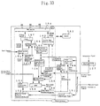
- Fig. 33 is a block diagram illustrating an arrangement of a micro-processor which is a main section of a synchronous motor driving device of a further embodiment according to the present invention.
- This synchronous motor driving device is different from the synchronous motor driving device illustrated in Fig. 30 in that a compensation phase coefficient generation section 168 for obtaining and outputting a compensation phase coefficient by inputting the integration signal level detection signal output from the integration signal level detecting circuitry 127 (refer to Fig. 21 ) and the compensation phase pattern output from the compensation phase pattern mode selection section 156 is employed instead of the compensation phase coefficient generation section 155, and wherein the compensation phase coefficient output from the compensation phase pattern mode selection section 156 and the compensation phase coefficient output from the compensation phase coefficient generation section 168 are multiplied so as to obtain and output the compensation phase amount command.
- Fig. 34 is a flowchart useful in understanding the operation for obtaining a compensation phase amount command.
- step SP1 a compensation phase pattern mode is read, in step SP2, a compensation phase pattern (for example, sin ⁇ n) is read based upon the compensation phase pattern mode, in step SP3, an integration signal level detection signal is compared with a predetermined value so that it is judged whether or not the integration signal level detection signal is greater.
- a compensation phase pattern for example, sin ⁇ n
- step SP4 When it is judged that the integration signal level detection signal is greater, in step SP4, a compensation phase coefficient K is increased by ⁇ sin ⁇ n. On the contrary, when it is judged that the integration signal level detection signal is smaller, in step SP5, the compensation phase coefficient K is decreased by ⁇ sin ⁇ n.
- ⁇ is a constant which is experimentally determined.
- the pattern of the phase changing component is successively corrected so as to determine the integration signal level detection signal to be a predetermined value, as a result, control with efficiency is securely carried out.
- Fig. 35 is a chart illustrating a relationship between an integration signal level and a phase changing component. Wherein, a dashed line illustrated in Fig. 35 is an integration signal level which makes an efficiency to be a maximum efficiency.
- Fig. 36 is a block diagram illustrating an arrangement of a micro-processor which is a main section of a brushless DC motor driving device of an embodiment of the present invention. Arrangement of a section other than the micro-processor is similar as that of the arrangement illustrated in Fig. 21 , therefore detailed description is omitted. Further, a brushless DC motor is employed as the synchronous motor. Furthermore, this brushless DC motor driving device carries out a speed control using a voltage amplitude.
- a magnetic pole position detection signal output from a position detector is supplied to an exterior interruption terminal of the micro-processor.
- an interruption processing for a phase correction timer 18a, interval measurement timer 18b, and compensation voltage pattern mode selection section 19g" , and an interruption processing for a compensation phase pattern mode selection section 19m are carried out by the magnetic pole position detection signal supplied to the exterior interruption terminal.
- the phase correction timer 18a is set a timer value by a timer value calculating section 19a (described later).
- the interval measurement timer 18b obtains a timer value by measuring an interval of the magnetic pole position detection signal and supplies the timer value to a position signal interval calculating section 19b which is included in a CPU 19.
- the position signal interval calculating section 19b receives the timer value from the interval measurement timer 18b, calculates intervals of voltage patterns of stator windings 13u, 13v and 13w, and outputs a position signal interval signal which represents an interval.
- the phase correction timer 18a supplies a count-over signal to an inverter mode selection section 19c which is included in the CPU 19 and carries out an interruption processing (refer to the interruption processing 2 in Fig. 36 ).
- the inverter mode selection section 19c reads out a corresponding voltage pattern from a memory 18c and outputs the voltage pattern therefrom.
- the compensation voltage pattern mode selection section 19g" reads out a corresponding compensation voltage pattern from the memory 18c and outputs the compensation voltage pattern therefrom.
- the compensation phase pattern mode selection section 19m reads out a corresponding compensation phase pattern from the memory 18c and outputs the compensation phase pattern therefrom.
- an calculation is carried out based upon the timer value by the position signal interval calculating section 19b so as to output a position signal interval signal.
- the position signal interval signal is supplied to the timer value calculating section 19a and a speed calculating section 19e.
- the speed calculating section 19e calculates a present speed based upon the position signal interval signal from the position signal interval calculating section 19b and supplies the present speed to a speed control section 19f.
- a speed command is also supplied to the speed control section 19f.
- the speed control section 19f outputs an average voltage command based upon the speed command and the present speed from the speed calculating section 19e.
- the compensation phase pattern output from the compensation phase pattern mode selection section 19m and an average phase amount command are supplied to an adder 19n, and a sum of the both is supplied as a phase amount command to the timer value calculating section 19a.
- the timer value calculating section 19a calculates the timer value which is to be set in the phase correction timer 18a based upon the phase amount command and the position signal interval signal from the position signal interval calculating section 19b.
- the average voltage command and the compensation voltage pattern output from the compensation voltage pattern mode selection section 19g" are supplied to an adder 19h, and a sum of the both is output as a voltage command.
- the voltage pattern output from the inverter mode selection section 19c and the voltage command output from the adder 19h are supplied to a PWM (pulse width modulation) section 18d.
- the PWM section 18d outputs voltage commands for three phases. These voltage commands are supplied to a base driving circuitry 20.
- the base driving circuitry 20 outputs control signals each of which is to be supplied to each base terminal of switching transistors 121u1, 121u2, 121v1, 121v2, 121w1 and 121w2 of the inverter.
- each component section included within the CPU 19 is merely represented its functional section for performing corresponding function as the component section. Those component sections do not exist in the CPU 19 under a condition that each component section is clearly distinguished.
- the position signal which is reversed its level periodically is output, as is illustrated in Fig. 39(A) .
- the interruption processing 1 is carried out at timings corresponding to standing and falling of the position signal.
- the compensation voltage pattern mode is changed, as is illustrated in Fig. 39 (C) , so that the compensation voltage pattern which is illustrated in Fig. 39(B) is output.
- the compensation phase pattern mode is changed, as is illustrated in Fig. 39(E) , so that the compensation phase pattern which is illustrated in Fig. 39(D) is output.
- the compensation phase pattern is determined so that changing of peak value of the integration signal is reduced which is illustrated in Fig, 42 .
- the sum of the compensation phase pattern and the average phase amount command is supplied to the timer value calculating section 19a as the phase amount command, and the timer value of the phase correction timer 18a is determined based upon the output from the timer value calculating section 19a, so that the timer value is increased or decreased, as is illustrated in Fig. 39 (F) .
- the phase correction timer 18a has its timer value determined by the timer value calculating section 19a, the phase correction timer 18a is count-over when the phase correction timer performs a counting operation for the determined timer value ⁇ refer to the ending points of the arrows in Fig. 39(F) ⁇ .
- the interruption processing 2 is carried out at every occurrence of the count-over of the phase correction timer 18a, so that the inverter mode selection section 19c advances the inverter mode by 1 step. That is, the inverter mode is selected in the order of "2""3""4" ... "0""1"”2" ... .
- the ON-OFF condition of the switching transistors 121u1, 121u2, 121v1, 121v2, 121w1 and 121w2 is controlled, as illustrated in Figs. 39(G) to 39(L) , corresponding to each inverter mode, by advancing the inverter mode by 1 step by the interruption processing 2.
- the integration signal level'and the inverter voltage phase have a relationship such that the level of the integration signal is increased by advancing the inverter voltage phase and that the level of the integration signal is decreased by delaying the inverter voltage phase, as is illustrated in Fig. 40 . Therefore, the beat phenomenon in the integration signal is greatly reduced, as is illustrated in Figs. 41 , by carrying out the processing based upon the device illustrated in Fig. 36 , so that the position signal (integration signal) is stabilized and the driving range of the brushless DC motor is enlarged when the torque control is performed.
- Figs. 42 are charts illustrating the integration signal, motor speed and compensation voltage pattern when the determination of the timer value based upon the compensation phase pattern is not carried out. The beat phenomenon to some degree is generated in the integration signal. Further, Figs. 41 illustrate the integration signal, motor speed, compensation voltage pattern and compensation phase pattern.
- Fig, 37 is a flowchart useful in understanding the operation of the interruption processing 1.
- An external interruption requirement is accepted at standing edges and falling edges, respectively, of the magnetic pole position detection signal (corresponding to the excitement change-over signal) from the position detection section.
- step SP1 the phase amount command is calculated based upon the sum of the average phase amount (average phase correction angle) from the exterior and the compensation phase pattern selected by the compensation pattern mode selection section 19m, in step SP2, the value of the phase correction timer 18a is calculated based upon the phase amount command, in step SP3, the correction timer value is set in the phase correction timer 18a, in step SP4, the phase correction timer 18a is started.
- step SP5 the interval measurement timer 18b is stopped which has started by the previous interruption processing 1, in step SP6, the interval measurement timer value is read (is memorized).
- the operations in steps SP5 and SP6 are operations for detecting an interval of edges of the position signal.
- step SP7 the interval measurement timer 18b is immediately reset and is started again for the next interval measurement.
- step SP8 calculation of the memorized position signal interval (for example, calculation of a count number per 1 degree in electrical angle) is carried out, in step SP9, the rotation speed at the present time of the brushless DC motor 13 is calculated based upon the position signal interval calculation result, in step SP10, the speed control is carried out based upon the speed command so as to calculate the average voltage command, in step SP11, the compensation voltage pattern is added to the average voltage command and the sum is output, then the operation returns to an original processing.
- Fig. 38 is a flowchart useful in understanding the operation of the interruption processing 2.
- the interruption processing 2 is accepted at every count-over of the phase correction timer 18a which has started in the interruption processing 1.
- step SP1 the inverter mode previously determined in the memory 18c is advanced by 1 step, in step SP2, the voltage pattern corresponding to the advanced inverter mode is output, then the operation returns to an original processing.
- Fig. 43 is a block diagram illustrating an arrangement of a micro-processor which is a main section of a brushless DC motor driving device of another embodiment according to the present invention. A portion other than the micro-processor has a similar arrangement to that in Fig. 21 , therefore description in detail is omitted. Further, this brushless DC motor driving device performs the speed control using a voltage phase.
- This brushless DC motor driving device is different from the brushless DC motor in Fig. 36 in that a speed control section 19f' for outputting an average phase amount command by inputting the present speed output from the speed calculating section 19e and the speed command from the exterior is employed instead of the speed control section 19f, that the compensation phase pattern output from the compensation phase pattern mode selection section 19m and the average phase amount command are supplied to the adder 19n so as to obtain the phase amount command and the phase amount command is supplied to the timer value calculation section 19a, and that the average voltage command from the exterior and the compensation voltage pattern output from the compensation voltage pattern mode selection section 19g" are supplied to the adder 19h so as to obtain the voltage command and the voltage command is supplied to the PWM section 18d.
- the position signal which is reversed in level periodically, is illustrated in Fig. 45(A) .
- the interruption processing 1 is carried out at every timing of standing and falling of the position signal, the compensation voltage pattern mode changes, as is illustrated in Fig. 45 (E) , so that the compensation voltage pattern illustrated in Fig. 45 (D) is output.
- the compensation phase pattern mode is changed, as is illustrated in Fig. 45(C) , so that the compensation pattern illustrated in Fig. 45 (B) is output.
- the sum of the compensation phase pattern and the average phase amount command output from the speed control section 19f' is supplied as the phase amount command to the timer value calculating section 19a so that the timer value in the phase correction timer 18a is determined by the output from the timer value calculating section 19a. Therefore, the timer value is" increased or decreased, as is illustrated in Fig. 45(F) . Though this phase correction timer 18a is determined by the timer value calculating section 19a, the phase correction timer 18a is count-over when the phase correction timer 18a has performed a count operation for the determined timer value ⁇ refer to the ending points of the arrows in Fig. 45(F) ⁇ .
- the interruption processing 2 is carried out at every count-over of the phase correction timer 18a so that the inverter mode selection section 19c advances the inverter mode by 1 step. That is, the inverter mode is sequentially selected in the order of "2""3""4" ... "0""1"”2" ... . And, the ON-OFF condition of the switching transistors 121u1, 121u2, 121v1, 121v2, 121w1 and 121w2 is controlled corresponding to each inverter mode, as illustrated in Figs. 45(G) to 45(L) , by advancing the inverter mode by 1 step by the interruption processing 2.
- the beat phenomenon of the integration signal is greatly reduced so that the position signal (integration signal) is stabilized and the driving range of the brushless DC motor under the torque control is enlarged, as is similar as the brushless DC motor driving device illustrated in Fig. 36 .
- Fig. 44 is a flowchart useful in understanding the operation of the interruption processing 1.
- the external interruption requirement is accepted at every standing edge and falling edge of the magnetic pole position detection signal (corresponds to the above excitement change-over signal) of the position detecting section.
- step SP1 the interval measurement timer 18b is stopped, in step SP2, interval measurement timer-value is read.
- the operations in steps SP1 and SP2 are operations for detecting an interval of edges of the position signal. Therefore, after reading of the interval measurement timer value, in step SP3, the interval measurement timer 18b is immediately stopped and is started again for the next interval measurement.
- step SP4 calculation of the memorized position signal interval (calculation of a count number per 1 degree in electric angle) is carried out, in step SP5, the present rotation speed of the brushless DC motor is calculated based upon the position signal interval calculation result, in step SP6, the average phase amount command is calculated by carrying out the speed control based upon the speed command, in step SP7, the phase amount command is obtained by adding the compensation phase pattern to the average phase amount command, in step.SP8, the timer value to be set in the phase correction timer 18a is calculated based upon the phase amount command, in step SP9, the calculated timer value is set in the phase correction timer 18a, in step SP10, the phase correction timer 18a is started, in step SP11, the voltage command is output by adding the compensation voltage pattern to the average voltage command, then the operation returns to an original processing.
- Fig. 46 is a block diagram illustrating an arrangement of a micro-processor which is a main section of a brushless DC motor of yet another embodiment according to the present invention.
- the block diagram illustrates the brushless DC motor driving device in Fig. 36 in more detail.
- the arrangement other than the micro-processor is similar to the arrangement in Fig. 21 , therefore description thereof is omitted.
- this brushless DC motor driving device performs the speed control based upon the voltage amplitude.
- This brushless DC motor driving device is different from the brushless DC motor driving device in Fig. 36 in that a compensation voltage coefficient generation section 19i' for outputting a previously determined (compensation voltage coefficient (a value between 0 and 1) based upon the present speed from the speed calculating section 19e, and a compensation phase coefficient generating section 19p for outputting a previously determined compensation phase coefficient (a value between 0 and 1) based upon the present speed from the speed calculating section 19e are further provided.
- a multiplication section 19j is further provided for outputting a compensation voltage pattern by inputting the average voltage command output from the speed control section 19f, the compensation voltage coefficient output from the compensation voltage coefficient generation section 19i' and the compensation voltage pattern output from the compensation voltage pattern mode selection section 19g" .
- a multiplication section 19q is further provided for outputting a compensation phase pattern by inputting the average phase amount command given from the exterior, the compensation phase coefficient output from the compensation phase coefficient generation section 19p and the compensation phase pattern output from the compensation phase pattern mode selection section 19m.
- the average voltage command output from the speed control section 19f and the compensation voltage pattern output from the multiplication section 19j are supplied to the adder 19h and the sum of the both is output as the voltage command
- the average phase amount command given from the exterior and the compensation phase pattern output from the multiplication section 19q are supplied to the adder 19n and the sum of the both is output as the phase amount command.
- Figs. 47 and 48 are a flowchart useful in understanding an operation of the interruption processing 1 in Fig. 46 .
- the external interruption requirement is accepted at standing edges and falling edges of the magnetic pole position detection signal (corresponds to the above excitement change-over signal) of the position detection section.
- step SP1 the interval measurement timer 18b is stopped, in step SP2, the interval measurement timer value is read.
- the operations in steps SP1 and SP2 are operations for detecting an interval of the edges of the position signal. Therefore, after the reading of the interval measurement timer value, in step SP3, the interval measurement timer 18b is immediately reset and is started again for the next interval measurement.
- step SP4 calculation of the memorized position signal interval (for example, calculation of a count number per 1 degree in electric angle) is carried out, in step SP5, the present, speed of the brushless DC motor is calculated based upon the position signal interval calculation result, in step SP6, the compensation phase pattern is read based upon the compensation phase pattern mode, in step SP7, the compensation phase pattern mode is advanced by 1 step.
- step SP8 the compensation phase coefficient is read based upon the present speed
- step SP9 the compensation phase is calculated by multiplying the multiplication result of the average phase amount command and the compensation phase coefficient to the compensation phase pattern
- step SP10 the phase amount command is calculated by adding the compensation phase and the average phase amount command
- step SP11 the timer value which should be set in the phase correction timer 18a is calculated based upon the phase amount command
- step SP12 the timer value is set in the phase correction timer 18a
- step SP13 the phase correction timer 18a is started.
- step SP14 the average voltage command is calculated by performing the speed control based upon the speed command given from the exterior.
- step SP15 the compensation voltage pattern is read based upon the compensation voltage pattern mode.
- step SP16 the compensation voltage pattern mode is advanced by 1 step.
- step SP17 the compensation voltage coefficient is read based upon the present rotation speed.
- step SP18 the compensation voltage is calculated by multiplying the multiplication result of the average voltage amount command and the compensation voltage coefficient to the compensation voltage pattern.
- step SP19 the voltage command is calculated by adding the compensation voltage and the average voltage command, then the operation returns to an original processing.
- the compensation phase pattern mode selection section 19m selects the compensation phase pattern so as to suppress the beat phenomenon of the integration signal. But, it is possible that the inverter interval is divided, the level of the integration signal is judged whether it is great or small at every divided interval, and in responding to the judgment result, the inverter voltage phase is delayed when the level of the integration signal is great, or the inverter voltage phase is advanced when the level of the integration signal is small.
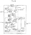
- Fig. 49 is a block diagram illustrating an arrangement of a micro-processor which is a main section of a brushless DC motor of a yet further embodiment according to the present invention.
- the block diagram illustrates the brushless DC motor driving device in Fig. 43 in more detail.
- the arrangement other than the micro-processor is similar to the arrangement in Fig. 21 , therefore description thereof is omitted.
- this brushless DC motor driving device performs the speed control based upon the phase amplitude.
- This brushless DC motor driving device is different from the brushless DC motor driving device in Fig. 43 in that a compensation voltage coefficient generation section 19i' for outputting a previously determined compensation voltage coefficient (a value between 0 and 1) based upon the present speed from the speed calculating section 19e, and a compensation phase coefficient generating section 19p for outputting a previously determined compensation phase coefficient (a value between 0 and 1) based upon the present speed from the speed calculating section 19e are further provided.
- a multiplication section 19j is further provided for outputting a compensation voltage pattern by inputting the average voltage command given from the exterior, the compensation voltage coefficient output from the compensation voltage coefficient generation section 19i' and the compensation voltage pattern output from the compensation voltage pattern mode selection section 19g" .
- a multiplication section 19q is further provided for outputting a compensation phase pattern by inputting the average phase amount command-output from the speed controlling section 19f, the compensation phase coefficient output from the compensation phase coefficient, generation section 19p and the compensation phase pattern output-from the compensation phase pattern mode selection section 19m.
- the average voltage command given from the exterior and the compensation voltage pattern output from the multiplication section 19j are supplied to the adder 19h and the sum of the both is output as the voltage command
- the average phase amount command output from the speed control section 19f and the compensation phase pattern output from the multiplication section 19q are supplied to the adder 19n and the sum of the both is output as the phase amount command.
- Figs. 50 and 51 are a flowchart useful in understanding an operation of the interruption processing 1 in Fig. 49 .
- the external interruption requirement is accepted at standing edges and falling edges of the magnetic pole position detection signal (corresponds to the above excitement change-over signal) of the position detection section.
- step SP1 the interval measurement timer 18b is stopped, in step SP2, the interval measurement timer value is read.
- the operations in steps SP1 and SP2 are operations for detecting an interval of the edges of the position signal. Therefore, after the reading of the interval measurement timer value, in step SP3, the interval measurement timer 18b is immediately reset and is started again for the next interval measurement.
- step SP4 calculation of the memorized'position signal interval (for example, calculation of a count number per 1 degree in electric angle) is carried out, in step SP5, the present speed of the brushless DC motor is calculated based upon the position signal interval calculation result, in step SP6, the average phase amount command is calculated by performing the speed control based upon the speed command given from the exterior, in step SP7, the compensation phase pattern is read based upon the compensation phase pattern mode, in step SP8, the compensation phase pattern mode is advance by 1 step.
- the memorized'position signal interval for example, calculation of a count number per 1 degree in electric angle
- step SP9 the compensation phase coefficient is read based upon the present speed
- step SP10 the compensation phase is calculated by multiplying the multiplication result of the average phase amount command and the compensation phase coefficient to the compensation phase pattern
- step SP11 the phase amount command is calculated by adding the compensation phase and the average phase amount command
- step SP12 the timer value which should be set in the phase correction timer 18a is calculated based upon the phase amount command
- step SP13 the timer value is set in the phase correction timer 18a
- step SP14 the phase correction timer 18a is started.
- step SP15 the compensation voltage pattern is read based upon the compensation voltage pattern mode
- step SP16 the compensation voltage pattern mode is advanced by 1 step.
- step SP17 the compensation voltage coefficient is read based upon the present rotation speed
- step SP18 the compensation voltage is calculated by multiplying the multiplication result of the average voltage amount command and the compensation voltage coefficient to the compensation voltage pattern
- step SP19 the voltage command is calculated by adding the compensation voltage and the average voltage command, then the operation returns to an original processing.
- the present invention can realize the torque control for reducing low speed vibration of a cyclic intermittent load with a maximum efficiency condition and with a practical arrangement, and is applicable to various applications in which a cyclic intermittent load is driven using a synchronous motor or brushless DC motor.
Claims (22)
- Dispositif de commande de moteur synchrone comprenant :des moyens de commande d'onduleur (8) (10) (28) (30) (48) (50) (68) (70) (88) (90) (108) (110) (126) pour commander un onduleur (5) (5b) (25) (45) (65) (85) (105) (121) de manière à ajouter (3) une quantité variable à une amplitude et à une phase d'une commande de courant ou d'une commande de tension lorsqu'une commande de couple est effectuée pour supprimer une variation de vitesse pendant une rotation par un moteur synchrone (6) commandé par un onduleur (5) (5b) (25) (45) (65) (85) (105) (121), lequel moteur (6) commande une charge ayant une variation de couple cyclique.
- Dispositif selon la revendication 1, dans lequel les moyens de commande d'onduleur (8) (10) (28) (30) (48) (50) (68) (70) (88) (90) (108) (110) (126) sont des moyens pour commander une quantité variable de phase sur la base d'une quantité variable d'amplitude qui est commandée sur la base d'une sortie d'une section de commande de couple (10) (30) (110).
- Dispositif selon la revendication 1, dans lequel les moyens de commande d'onduleur (48) (50) (126) sont des moyens pour commander une quantité variable d'amplitude sur la base d'une quantité variable de phase qui est commandée sur la base d'une sortie d'une section de commande de couple (50).
- Dispositif selon la revendication 1, dans lequel les moyens de commande d'onduleur (68) (70) (126) sont des moyens pour commander une quantité variable d'amplitude sur la base d'une sortie d'une section de commande de couple (70) et pour commander une quantité variable de phase sur la base d'une quantité de détection correspondant à un rendement.
- Dispositif selon la revendication 1, dans lequel les moyens de commande d'onduleur (88) (90) (126) sont des moyens pour commander une quantité variable de phase sur la base d'une sortie d'une section de commande de couple (90) et pour commander une quantité variable d'amplitude sur la base d'une quantité de détection correspondant à un rendement.
- Dispositif selon l'une des revendications 1 à 5, dans lequel les moyens de commande d'onduleur (8) (10) (28) (30) (48) (50) (68) (70) (88) (90) (108) (110) (126) utilisent une quantité correspondant à une onde fondamentale et à des harmoniques inférieures en tant que quantité variable.
- Dispositif selon l'une des revendications 1 à 5, dans lequel les moyens de commande d'onduleur (8) (10) (28) (30) (48) (50) (68) (70) (88) (90) (108) (110) (126) utilisent une quantité correspondant à une onde fondamentale en tant que quantité variable.
- Dispositif selon l'une des revendications 1 à 5, dans lequel les moyens de commande d'onduleur (8) (10) (28) (30) (48) (50) (68) (70) (88) (90) (108) (110) (126) sont des moyens pour superposer une troisième harmonique à la quantité variable d'amplitude.
- Dispositif selon l'une des revendications 1 à 8, comprenant en outre des résistances (122u) (122v) (122w) ayant chacune une extrémité connectée à une borne de sortie de chaque phase de l'onduleur (121) et une autre extrémité connectée aux autres de sorte qu'une première tension de point milieu est obtenue, des enroulements de stator (6u) (6v) (6w) de chaque phase du moteur synchrone (6) qui sont connectés chacun à une extrémité aux autres de sorte qu'une deuxième tension de point milieu est obtenue, des moyens d'intégration (124a) (124b) pour intégrer une différence entre la première tension de point milieu et la deuxième tension de point milieu et pour obtenir un signal d'intégration, et des moyens de détection de position de pôle magnétique (125) pour détecter une position de pôle magnétique d'un rotor (6a) du moteur synchrone (6) sur la base du signal d'intégration.
- Dispositif d'entraînement de compresseur comprenant :un compresseur à un cylindre, etun moteur synchrone pour entraîner le compresseur à un cylindre qui est commandé par le dispositif de commande de moteur synchrone selon l'une des revendications 1 à 9.
- Dispositif selon la revendication 1, dans lequel les moyens de commande d'onduleur (18) utilisent une tension variable qui est en avance par rapport à une phase d'un couple de charge en tant que quantité variable, et
utilisent une commande de tension de valeur moyenne en tant que forme d'onde de tension, et
exécutant une opération de superposition en synchronisation avec une intermittence du couple de charge pour une application au moteur (6),
le dispositif comprenant en outre :des résistances (122u) (122v) (122w) ayant chacune une extrémité connectée à une borne de sortie de chaque phase de l'onduleur (121) et une autre extrémité connectée aux autres de sorte qu'une première tension de point milieu est obtenue,des enroulements de stator (6u) (6v) (6w) correspondant chacun à chaque phase du moteur (6), chacun des enroulements de stator (6u) (6v) (6w) étant connecté à une extrémité aux autres de sorte qu'une deuxième tension de point milieu est obtenue,des moyens d'intégration (124a) (124b) pour intégrer une différence entre la première tension de point milieu et la deuxième tension de point milieu et pour obtenir un signal d'intégration,des moyens de détection de position de pôle magnétique (125) pour détecter une position de pôle magnétique d'un rotor (6a) du moteur (6) sur la base du signal d'intégration, etdes moyens de suppression de variation de valeur crête (19m) (19n) (19a) pour supprimer une variation de valeur crête du signal d'intégration. - Dispositif selon la revendication 11, dans lequel les moyens de suppression de variation de valeur crête (19m) (19n) (19a) comprennent des moyens de division pour diviser un intervalle d'onduleur, des moyens de jugement pour juger si le niveau du signal d'intégration est grand ou petit pendant chaque intervalle de division, et des moyens de commande de phase de tension d'onduleur (19m) (19n) (19a) pour retarder la phase de la tension d'onduleur en réponse au résultat de jugement indiquant que le niveau du signal d'intégration est grand et pour avancer la phase de la tension d'onduleur en réponse au résultat de jugement indiquant que le niveau du signal d'intégration est petit.
- Dispositif selon la revendication 1, dans lequel les moyens de commande d'onduleur (18) utilisent une phase variable qui est en avance par rapport à une phase d'un couple de charge en tant que quantité variable, et
utilisent une commande de phase de valeur moyenne en tant que forme d'onde de phase, et
exécutant une opération de superposition en synchronisation avec une intermittence du couple de charge pour une application au moteur (6),
le dispositif comprenant en outre :des résistances (122u) (122v) (122w) ayant chacune une extrémité connectée à une borne de sortie de chaque phase de l'onduleur (121) et une autre extrémité connectée aux autres de sorte qu'une première tension de point milieu est obtenue,des enroulements de stator (6u) (6v) (6w) correspondant chacun à chaque phase du moteur (6), chacun des enroulements de stator (6u) (6v) (6w) étant connecté à une extrémité aux autres de sorte qu'une deuxième tension de point milieu est obtenue,des moyens d'intégration pour intégrer une différence entre la première tension de point milieu et la deuxième tension de point milieu et pour obtenir un signal d'intégration,des moyens de détection de position de pôle magnétique (123a) (124a) (124b) (125) pour détecter une position de pôle magnétique d'un rotor (6a) du moteur (6) sur la base du signal d'intégration, etdes moyens de suppression de variation de valeur crête (19m) (19n) (19a) pour supprimer un variation d'une valeur crête du signal d'intégration. - Dispositif selon la revendication 13, dans lequel les moyens de suppression de variation de valeur crête (19m) (19n) (19a) comprennent des moyens de division pour diviser un intervalle d'onduleur, des moyens de jugement pour juger si le niveau du signal d'intégration est grand ou petit pendant chaque intervalle de division, et des moyens de commande d'amplitude de tension d'onduleur pour augmenter l'amplitude de la tension d'onduleur en réponse au résultat de jugement indiquant que le niveau du signal d'intégration est grand et pour diminuer l'amplitude de tension d'onduleur en réponse au résultat de jugement indiquant que le niveau du signal d'intégration est petit.
- Procédé de commande de moteur synchrone comprenant l'étape suivante :ajouter une quantité variable à une amplitude et à une phase d'une commande de courant ou d'une commande de tension lorsqu'une commande de couple est effectuée pour supprimer une variation de vitesse pendant une rotation par un moteur synchrone (6) commandé par un onduleur (5) (5b) (25) (45) (65) (85) (105) (121) lequel moteur (6) entraîne une charge ayant une variation de couple cyclique.
- Procédé de commande de moteur synchrone selon la revendication 15, dans lequel une quantité variable de phase est commandée sur la base d'une quantité variable d'amplitude qui est commandée sur la base d'une sortie d'une section de commande de couple (10) (30) (70) (110).
- Procédé de commande de moteur synchrone selon la revendication 15, dans lequel une quantité variable d'amplitude est commandée sur la base d'une quantité variable de phase qui est commandée sur la base d'une sortie d'une section de commande de couple (50) (90).
- Procédé de commande de moteur synchrone selon la revendication 15, dans lequel une quantité variable d'amplitude est commandée sur la base d'une sortie d'une section de commande de couple (10) (30) (70) (110), et une quantité variable de phase est commandée sur la base d'une quantité de détection qui est liée à un rendement.
- Procédé de commande de moteur synchrone selon la revendication 15, dans lequel une quantité variable de phase est commandée sur la base d'une sortie d'une section de commande de couple (50) (90), et une quantité variable d'amplitude est commandée sur la base d'une quantité de détection qui est liée à un rendement.
- Procédé de commande de moteur synchrone selon l'une des revendications 15 à 19, dans lequel une quantité correspondant à une onde fondamentale et à des harmoniques inférieures est utilisée en tant que quantité variable.
- Procédé de commande de moteur synchrone selon l'une des revendications 15 à 19, dans lequel une quantité correspondant à une onde fondamentale est utilisée en tant que quantité variable.
- Procédé de commande de moteur synchrone selon l'une des revendications 15 à 19, dans lequel une troisième harmonique est superposée à la quantité variable d'amplitude.
Applications Claiming Priority (3)
| Application Number | Priority Date | Filing Date | Title |
|---|---|---|---|
| JP21757396 | 1996-08-19 | ||
| JP21757396 | 1996-08-19 | ||
| PCT/JP1997/002875 WO1998008297A1 (fr) | 1996-08-19 | 1997-08-19 | Procede d'entrainement de moteur synchrone, procede d'entrainement de compresseur, dispositif pour ces procedes et dispositif d'entrainement de moteur a courant continu sans balai |
Publications (3)
| Publication Number | Publication Date |
|---|---|
| EP0982844A1 EP0982844A1 (fr) | 2000-03-01 |
| EP0982844A4 EP0982844A4 (fr) | 2000-03-01 |
| EP0982844B1 true EP0982844B1 (fr) | 2009-06-03 |
Family
ID=16706399
Family Applications (1)
| Application Number | Title | Priority Date | Filing Date |
|---|---|---|---|
| EP97935825A Expired - Lifetime EP0982844B1 (fr) | 1996-08-19 | 1997-08-19 | Dispositif d'entrainement de moteur a courant continu sans balai |
Country Status (9)
| Country | Link |
|---|---|
| US (1) | US6208109B1 (fr) |
| EP (1) | EP0982844B1 (fr) |
| JP (1) | JP3654652B2 (fr) |
| KR (2) | KR100592970B1 (fr) |
| CN (1) | CN1122356C (fr) |
| AT (1) | ATE433222T1 (fr) |
| DE (1) | DE69739441D1 (fr) |
| ES (1) | ES2328303T3 (fr) |
| WO (1) | WO1998008297A1 (fr) |
Families Citing this family (52)
| Publication number | Priority date | Publication date | Assignee | Title |
|---|---|---|---|---|
| DE10037972B4 (de) * | 1999-08-05 | 2005-09-15 | Sharp K.K. | Vorrichtung und Verfahren zur Elektromotorsteuerung |
| US6392418B1 (en) * | 1999-09-16 | 2002-05-21 | Delphi Technologies, Inc. | Torque current comparison for current reasonableness diagnostics in a permanent magnet electric machine |
| JP3454210B2 (ja) * | 1999-11-30 | 2003-10-06 | 株式会社日立製作所 | 同期モータの位置センサレス制御方法 |
| GB2367332B (en) * | 2000-09-25 | 2003-12-03 | Compair Uk Ltd | Improvements in multi-stage screw compressor drive arrangements |
| CN1290252C (zh) * | 2000-11-09 | 2006-12-13 | 大金工业株式会社 | 同步电机控制方法及其装置 |
| EP1211798B1 (fr) | 2000-11-22 | 2018-01-10 | Nissan Motor Co., Ltd. | Méthode et dispositif de contrôle d'un moteur |
| EP1237274B1 (fr) * | 2001-03-02 | 2004-05-06 | Matsushita Electric Industrial Co., Ltd. | Contrôleur pour un moteur électrique |
| JP3818086B2 (ja) * | 2001-06-01 | 2006-09-06 | 株式会社日立製作所 | 同期モータの駆動装置 |
| JP3867518B2 (ja) * | 2001-06-06 | 2007-01-10 | 株式会社日立製作所 | 同期電動機のセンサレス制御システム |
| JP4075338B2 (ja) * | 2001-07-18 | 2008-04-16 | 株式会社豊田自動織機 | 電動圧縮機の制御方法 |
| JP3668870B2 (ja) * | 2001-08-09 | 2005-07-06 | 株式会社日立製作所 | 同期電動機駆動システム |
| US7190145B2 (en) * | 2002-01-16 | 2007-03-13 | Ballard Power Systems Corporation | Method and apparatus for improving speed measurement quality in multi-pole machines |
| JPWO2003071672A1 (ja) * | 2002-02-25 | 2005-06-16 | ダイキン工業株式会社 | 電動機制御方法およびその装置 |
| AU2006246513B2 (en) * | 2002-02-25 | 2008-03-20 | Daikin Industries, Ltd. | Motor control method and its apparatus |
| JP4357967B2 (ja) * | 2002-03-22 | 2009-11-04 | パナソニック株式会社 | シンクロナスリラクタンスモータの制御装置 |
| JP4407109B2 (ja) * | 2002-10-11 | 2010-02-03 | ダイキン工業株式会社 | 電動機制御方法およびその装置 |
| AU2006252022B2 (en) * | 2002-10-11 | 2007-08-23 | Daikin Industries, Ltd. | Motor control method and apparatus thereof |
| JP3771544B2 (ja) * | 2003-03-24 | 2006-04-26 | 株式会社日立製作所 | 永久磁石形同期電動機の制御方法及び装置 |
| EP1617551A4 (fr) * | 2003-04-22 | 2010-09-08 | Panasonic Corp | Dispositif de commande du moteur, compresseur, climatiseur et refrigerateur |
| US6859001B2 (en) * | 2003-07-24 | 2005-02-22 | General Electric Company | Torque ripple and noise reduction by avoiding mechanical resonance for a brushless DC machine |
| US20050135794A1 (en) * | 2003-12-22 | 2005-06-23 | General Electric Company | Method and system for negative torque reduction in a brushless DC motor |
| US7606011B2 (en) * | 2004-04-15 | 2009-10-20 | Sundyne Corporation | Motor controller with automated input power determination |
| JP2006017041A (ja) * | 2004-07-02 | 2006-01-19 | Kobe Steel Ltd | 回転式圧縮機 |
| JP4513445B2 (ja) * | 2004-07-22 | 2010-07-28 | 株式会社デンソー | 圧縮機駆動用モータの制御方法およびその装置 |
| JP4583111B2 (ja) * | 2004-08-31 | 2010-11-17 | ルネサスエレクトロニクス株式会社 | モータの駆動制御装置およびディスク回転システム |
| JP4729356B2 (ja) * | 2005-07-29 | 2011-07-20 | 株式会社日立製作所 | モータ制御装置,洗濯機,エアコンおよび電動オイルポンプ |
| US7187152B1 (en) * | 2005-10-14 | 2007-03-06 | Delta Electronic Inc. | AC servo drive without current sensor |
| JP4926492B2 (ja) * | 2006-02-20 | 2012-05-09 | 本田技研工業株式会社 | モータ制御装置 |
| JP2009538103A (ja) * | 2006-05-18 | 2009-10-29 | パナソニック株式会社 | モータ駆動装置 |
| JP4720653B2 (ja) * | 2006-07-07 | 2011-07-13 | トヨタ自動車株式会社 | 電動機制御装置およびそれを備えた車両 |
| JP5167631B2 (ja) * | 2006-11-30 | 2013-03-21 | 株式会社デンソー | モータの制御方法及びそれを利用するモータ制御装置 |
| KR101364204B1 (ko) * | 2007-05-29 | 2014-02-17 | 엘지전자 주식회사 | 모터 드라이버 시스템 및 모터 드라이버 보호방법 |
| WO2008146381A1 (fr) * | 2007-05-31 | 2008-12-04 | Mitsubishi Electric Corporation | Convertisseur de secteur |
| KR100964368B1 (ko) * | 2007-10-31 | 2010-06-17 | 엘지전자 주식회사 | 공기조화기의 전동기 제어방법 및 그 제어 장치 |
| JP2009303287A (ja) * | 2008-06-10 | 2009-12-24 | Nidec Shibaura Corp | モータ制御装置 |
| JP4883151B2 (ja) * | 2009-08-05 | 2012-02-22 | 株式会社デンソー | 回転機の制御装置 |
| US8227929B2 (en) * | 2009-09-25 | 2012-07-24 | General Electric Company | Multi-use energy storage for renewable sources |
| KR101694539B1 (ko) * | 2010-02-08 | 2017-01-09 | 엘지전자 주식회사 | 공기 조화기의 압축기 구동장치 및 그 구동방법 |
| US8657585B2 (en) * | 2010-02-08 | 2014-02-25 | Lg Electronics Inc. | Apparatus for driving compressor of air conditioner and method for driving the same |
| US8639388B2 (en) * | 2010-05-25 | 2014-01-28 | Raytheon Company | Time domain vibration reduction and control |
| RU2013108278A (ru) * | 2010-07-26 | 2014-09-10 | Мицубиси Электрик Корпорейшн | Способ управления для устройства управления двигателем |
| CN103518110B (zh) * | 2011-05-09 | 2016-08-31 | 松下电器产业株式会社 | 冰箱 |
| JP5920769B2 (ja) * | 2011-09-27 | 2016-05-18 | 株式会社ミツバ | ブラシレスモータ制御方法及びブラシレスモータ制御装置並びに電動パワーステアリング装置 |
| CN102400917B (zh) * | 2011-11-03 | 2014-05-21 | 周海波 | 一种降低封闭式永磁压缩机震动和噪音的方法 |
| JP5259851B1 (ja) * | 2012-03-28 | 2013-08-07 | オリンパス株式会社 | 位置制御装置 |
| JP5494760B2 (ja) * | 2012-08-30 | 2014-05-21 | ダイキン工業株式会社 | 電動機制御装置 |
| KR102136804B1 (ko) * | 2013-01-23 | 2020-07-22 | 엘지전자 주식회사 | 모터 제어 장치 및 그 제어 방법 |
| JP5737445B2 (ja) * | 2013-03-05 | 2015-06-17 | ダイキン工業株式会社 | 電力変換器制御装置 |
| KR101535036B1 (ko) * | 2014-08-25 | 2015-07-24 | 현대자동차주식회사 | 구동모터의 전류지령에 대한 토크 보상장치 및 방법 |
| GB2530293B (en) * | 2014-09-17 | 2017-08-02 | Nidec Control Techniques Ltd | Method of controlling a power output of an inverter drive |
| KR101519597B1 (ko) * | 2015-02-03 | 2015-05-13 | 이승철 | 교류 모터 이상상태 검출장치 및 이를 구비한 배전반 |
| CN111649774B (zh) * | 2020-06-23 | 2021-12-07 | 北京控制工程研究所 | 一种旋转变压器测角误差硬件自校正系统和方法 |
Citations (1)
| Publication number | Priority date | Publication date | Assignee | Title |
|---|---|---|---|---|
| US5469215A (en) * | 1993-08-02 | 1995-11-21 | Okuma Corporation | Method and apparatus for controlling an electric motor with compensation or torque ripple |
Family Cites Families (9)
| Publication number | Priority date | Publication date | Assignee | Title |
|---|---|---|---|---|
| JPS5413919A (en) * | 1977-07-04 | 1979-02-01 | Hitachi Ltd | Preventive controller for torque pulsation |
| US5272429A (en) * | 1990-10-01 | 1993-12-21 | Wisconsin Alumni Research Foundation | Air gap flux measurement using stator third harmonic voltage and uses |
| US5223775A (en) * | 1991-10-28 | 1993-06-29 | Eml Research, Inc. | Apparatus and related method to compensate for torque ripple in a permanent magnet electric motor |
| US5422570A (en) * | 1993-12-30 | 1995-06-06 | Whirlpool Corporation | Speed sensing for the third harmonic stator voltage signal |
| US5481166A (en) * | 1993-12-30 | 1996-01-02 | Whirlpool Corporation | Motor control for brushless permanent magnet using only three wires |
| ES2167444T3 (es) * | 1994-07-25 | 2002-05-16 | Daikin Ind Ltd | Motor capaz de producir un rendimiento elevado y procedimiento de control de dicho motor. |
| JPH08126377A (ja) * | 1994-10-19 | 1996-05-17 | Fujitsu General Ltd | モータの制御方法 |
| DE4442151A1 (de) * | 1994-11-26 | 1996-05-30 | Philips Patentverwaltung | Schaltungsanordnung zum Steuern eines elektronisch kommutierten Motors |
| US5798631A (en) * | 1995-10-02 | 1998-08-25 | The State Of Oregon Acting By And Through The State Board Of Higher Education On Behalf Of Oregon State University | Performance optimization controller and control method for doubly-fed machines |
-
1997
- 1997-08-19 EP EP97935825A patent/EP0982844B1/fr not_active Expired - Lifetime
- 1997-08-19 WO PCT/JP1997/002875 patent/WO1998008297A1/fr not_active Application Discontinuation
- 1997-08-19 KR KR1020057010295A patent/KR100592970B1/ko not_active IP Right Cessation
- 1997-08-19 DE DE69739441T patent/DE69739441D1/de not_active Expired - Lifetime
- 1997-08-19 AT AT97935825T patent/ATE433222T1/de not_active IP Right Cessation
- 1997-08-19 CN CN97198891A patent/CN1122356C/zh not_active Expired - Fee Related
- 1997-08-19 KR KR1019997001379A patent/KR20000068244A/ko active Search and Examination
- 1997-08-19 ES ES97935825T patent/ES2328303T3/es not_active Expired - Lifetime
- 1997-08-19 JP JP51058198A patent/JP3654652B2/ja not_active Expired - Fee Related
-
1999
- 1999-02-19 US US09/252,666 patent/US6208109B1/en not_active Expired - Lifetime
Patent Citations (1)
| Publication number | Priority date | Publication date | Assignee | Title |
|---|---|---|---|---|
| US5469215A (en) * | 1993-08-02 | 1995-11-21 | Okuma Corporation | Method and apparatus for controlling an electric motor with compensation or torque ripple |
Also Published As
| Publication number | Publication date |
|---|---|
| EP0982844A1 (fr) | 2000-03-01 |
| CN1122356C (zh) | 2003-09-24 |
| WO1998008297A1 (fr) | 1998-02-26 |
| JP3654652B2 (ja) | 2005-06-02 |
| KR20000068244A (ko) | 2000-11-25 |
| US6208109B1 (en) | 2001-03-27 |
| KR100592970B1 (ko) | 2006-06-26 |
| EP0982844A4 (fr) | 2000-03-01 |
| KR20050088412A (ko) | 2005-09-06 |
| DE69739441D1 (de) | 2009-07-16 |
| ES2328303T3 (es) | 2009-11-11 |
| CN1234144A (zh) | 1999-11-03 |
| ATE433222T1 (de) | 2009-06-15 |
Similar Documents
| Publication | Publication Date | Title |
|---|---|---|
| EP0982844B1 (fr) | Dispositif d'entrainement de moteur a courant continu sans balai | |
| EP1083649A2 (fr) | Moteur capable de produire un rendement élevé et procédé de commande dudit moteur | |
| US7352151B2 (en) | Method of estimating magnetic pole position in motor and apparatus of controlling the motor based on the estimated position | |
| US6008618A (en) | Zero speed start-up for a speed sensorless induction motor drive | |
| US6339308B2 (en) | Vector control method for synchronous reluctance motor | |
| US5804939A (en) | Brushless D.C. motor driving and controlling method and apparatus therefor and electrical equipment | |
| EP0748038A2 (fr) | Système et méthode de commande de moteurs à aimants permanents sans balais | |
| US9917542B2 (en) | Input vector set for position detection of PM motors | |
| US20020097015A1 (en) | Motor control apparatus and motor control method | |
| US20090140674A1 (en) | Control apparatus for ac motor | |
| JP2004048868A (ja) | 同期電動機の速度制御装置 | |
| JP2002247876A (ja) | インバータ装置、圧縮機制御装置、冷凍・空調装置の制御装置、モータの制御方法、圧縮機、冷凍・空調装置 | |
| JP3397013B2 (ja) | 同期モータの制御装置 | |
| US20040251860A1 (en) | Advanced sensorless drive technique for brushless DC motors | |
| JP4744505B2 (ja) | モータ駆動制御装置、モータ駆動制御方法及び座標変換方法、並びに換気扇、液体用ポンプ、送風機、冷媒圧縮機、空気調和機及び冷蔵庫 | |
| US20210281205A1 (en) | Driving device, driving system, and method of driving electric motor | |
| JP2004040861A (ja) | モータの駆動装置 | |
| JP5136568B2 (ja) | 電動機の制御回路、及びその制御回路を用いた空気調和機 | |
| JP3544338B2 (ja) | 圧縮機モータの制御装置 | |
| JP2001119978A (ja) | ブラシレスdcモータ制御方法およびその装置 | |
| JP2005046000A (ja) | 同期モータ駆動方法、圧縮機駆動方法およびこれらの装置 | |
| JP3567598B2 (ja) | ブラシレスdcモータ駆動方法、圧縮機駆動方法およびこれらの装置 | |
| JP4802428B2 (ja) | 誘導電動機の制御方法 | |
| JPH0799800A (ja) | インバータ駆動空気調和機 | |
| JP3132380B2 (ja) | ブラシレスdcモータ駆動制御装置 |
Legal Events
| Date | Code | Title | Description |
|---|---|---|---|
| PUAI | Public reference made under article 153(3) epc to a published international application that has entered the european phase |
Free format text: ORIGINAL CODE: 0009012 |
|
| 17P | Request for examination filed |
Effective date: 19990506 |
|
| A4 | Supplementary search report drawn up and despatched |
Effective date: 19990826 |
|
| AK | Designated contracting states |
Kind code of ref document: A4 Designated state(s): AT BE CH DE DK ES FI FR GB GR IE IT LI LU MC NL PT SE Kind code of ref document: A1 Designated state(s): AT BE CH DE DK ES FI FR GB GR IE IT LI LU MC NL PT SE |
|
| 17Q | First examination report despatched |
Effective date: 20050215 |
|
| GRAP | Despatch of communication of intention to grant a patent |
Free format text: ORIGINAL CODE: EPIDOSNIGR1 |
|
| RTI1 | Title (correction) |
Free format text: SYNCHRONOUS MOTOR DRIVING DEVICE |
|
| GRAS | Grant fee paid |
Free format text: ORIGINAL CODE: EPIDOSNIGR3 |
|
| GRAA | (expected) grant |
Free format text: ORIGINAL CODE: 0009210 |
|
| AK | Designated contracting states |
Kind code of ref document: B1 Designated state(s): AT BE CH DE DK ES FI FR GB GR IE IT LI LU MC NL PT SE |
|
| REG | Reference to a national code |
Ref country code: GB Ref legal event code: FG4D |
|
| REG | Reference to a national code |
Ref country code: CH Ref legal event code: EP |
|
| REG | Reference to a national code |
Ref country code: IE Ref legal event code: FG4D |
|
| REF | Corresponds to: |
Ref document number: 69739441 Country of ref document: DE Date of ref document: 20090716 Kind code of ref document: P |
|
| PG25 | Lapsed in a contracting state [announced via postgrant information from national office to epo] |
Ref country code: FI Free format text: LAPSE BECAUSE OF FAILURE TO SUBMIT A TRANSLATION OF THE DESCRIPTION OR TO PAY THE FEE WITHIN THE PRESCRIBED TIME-LIMIT Effective date: 20090603 Ref country code: AT Free format text: LAPSE BECAUSE OF FAILURE TO SUBMIT A TRANSLATION OF THE DESCRIPTION OR TO PAY THE FEE WITHIN THE PRESCRIBED TIME-LIMIT Effective date: 20090603 |
|
| NLV1 | Nl: lapsed or annulled due to failure to fulfill the requirements of art. 29p and 29m of the patents act | ||
| REG | Reference to a national code |
Ref country code: ES Ref legal event code: FG2A Ref document number: 2328303 Country of ref document: ES Kind code of ref document: T3 |
|
| PG25 | Lapsed in a contracting state [announced via postgrant information from national office to epo] |
Ref country code: SE Free format text: LAPSE BECAUSE OF FAILURE TO SUBMIT A TRANSLATION OF THE DESCRIPTION OR TO PAY THE FEE WITHIN THE PRESCRIBED TIME-LIMIT Effective date: 20090903 Ref country code: NL Free format text: LAPSE BECAUSE OF FAILURE TO SUBMIT A TRANSLATION OF THE DESCRIPTION OR TO PAY THE FEE WITHIN THE PRESCRIBED TIME-LIMIT Effective date: 20090603 |
|
| PG25 | Lapsed in a contracting state [announced via postgrant information from national office to epo] |
Ref country code: BE Free format text: LAPSE BECAUSE OF FAILURE TO SUBMIT A TRANSLATION OF THE DESCRIPTION OR TO PAY THE FEE WITHIN THE PRESCRIBED TIME-LIMIT Effective date: 20090603 |
|
| PG25 | Lapsed in a contracting state [announced via postgrant information from national office to epo] |
Ref country code: PT Free format text: LAPSE BECAUSE OF FAILURE TO SUBMIT A TRANSLATION OF THE DESCRIPTION OR TO PAY THE FEE WITHIN THE PRESCRIBED TIME-LIMIT Effective date: 20091003 Ref country code: MC Free format text: LAPSE BECAUSE OF NON-PAYMENT OF DUE FEES Effective date: 20090831 |
|
| REG | Reference to a national code |
Ref country code: CH Ref legal event code: PL |
|
| PLBE | No opposition filed within time limit |
Free format text: ORIGINAL CODE: 0009261 |
|
| STAA | Information on the status of an ep patent application or granted ep patent |
Free format text: STATUS: NO OPPOSITION FILED WITHIN TIME LIMIT |
|
| PG25 | Lapsed in a contracting state [announced via postgrant information from national office to epo] |
Ref country code: LI Free format text: LAPSE BECAUSE OF NON-PAYMENT OF DUE FEES Effective date: 20090831 Ref country code: DK Free format text: LAPSE BECAUSE OF FAILURE TO SUBMIT A TRANSLATION OF THE DESCRIPTION OR TO PAY THE FEE WITHIN THE PRESCRIBED TIME-LIMIT Effective date: 20090603 Ref country code: CH Free format text: LAPSE BECAUSE OF NON-PAYMENT OF DUE FEES Effective date: 20090831 |
|
| 26N | No opposition filed |
Effective date: 20100304 |
|
| REG | Reference to a national code |
Ref country code: IE Ref legal event code: MM4A |
|
| PG25 | Lapsed in a contracting state [announced via postgrant information from national office to epo] |
Ref country code: IE Free format text: LAPSE BECAUSE OF NON-PAYMENT OF DUE FEES Effective date: 20090819 |
|
| PG25 | Lapsed in a contracting state [announced via postgrant information from national office to epo] |
Ref country code: GR Free format text: LAPSE BECAUSE OF FAILURE TO SUBMIT A TRANSLATION OF THE DESCRIPTION OR TO PAY THE FEE WITHIN THE PRESCRIBED TIME-LIMIT Effective date: 20090904 |
|
| PG25 | Lapsed in a contracting state [announced via postgrant information from national office to epo] |
Ref country code: LU Free format text: LAPSE BECAUSE OF NON-PAYMENT OF DUE FEES Effective date: 20090819 |
|
| PGFP | Annual fee paid to national office [announced via postgrant information from national office to epo] |
Ref country code: GB Payment date: 20120815 Year of fee payment: 16 |
|
| PGFP | Annual fee paid to national office [announced via postgrant information from national office to epo] |
Ref country code: IT Payment date: 20120810 Year of fee payment: 16 Ref country code: ES Payment date: 20120827 Year of fee payment: 16 Ref country code: DE Payment date: 20120816 Year of fee payment: 16 Ref country code: FR Payment date: 20120823 Year of fee payment: 16 |
|
| GBPC | Gb: european patent ceased through non-payment of renewal fee |
Effective date: 20130819 |
|
| PG25 | Lapsed in a contracting state [announced via postgrant information from national office to epo] |
Ref country code: DE Free format text: LAPSE BECAUSE OF NON-PAYMENT OF DUE FEES Effective date: 20140301 |
|
| REG | Reference to a national code |
Ref country code: DE Ref legal event code: R119 Ref document number: 69739441 Country of ref document: DE Effective date: 20140301 |
|
| REG | Reference to a national code |
Ref country code: FR Ref legal event code: ST Effective date: 20140430 |
|
| PG25 | Lapsed in a contracting state [announced via postgrant information from national office to epo] |
Ref country code: IT Free format text: LAPSE BECAUSE OF NON-PAYMENT OF DUE FEES Effective date: 20130819 |
|
| PG25 | Lapsed in a contracting state [announced via postgrant information from national office to epo] |
Ref country code: GB Free format text: LAPSE BECAUSE OF NON-PAYMENT OF DUE FEES Effective date: 20130819 |
|
| PG25 | Lapsed in a contracting state [announced via postgrant information from national office to epo] |
Ref country code: FR Free format text: LAPSE BECAUSE OF NON-PAYMENT OF DUE FEES Effective date: 20130902 |
|
| REG | Reference to a national code |
Ref country code: ES Ref legal event code: FD2A Effective date: 20140905 |
|
| PG25 | Lapsed in a contracting state [announced via postgrant information from national office to epo] |
Ref country code: ES Free format text: LAPSE BECAUSE OF NON-PAYMENT OF DUE FEES Effective date: 20130820 |