EP0982745B1 - Dispositif de verrouillage pour un outil motorisé - Google Patents
Dispositif de verrouillage pour un outil motorisé Download PDFInfo
- Publication number
- EP0982745B1 EP0982745B1 EP99306355A EP99306355A EP0982745B1 EP 0982745 B1 EP0982745 B1 EP 0982745B1 EP 99306355 A EP99306355 A EP 99306355A EP 99306355 A EP99306355 A EP 99306355A EP 0982745 B1 EP0982745 B1 EP 0982745B1
- Authority
- EP
- European Patent Office
- Prior art keywords
- latch
- handle
- switch
- axis
- trigger
- Prior art date
- Legal status (The legal status is an assumption and is not a legal conclusion. Google has not performed a legal analysis and makes no representation as to the accuracy of the status listed.)
- Expired - Lifetime
Links
Images

Classifications
-
- H—ELECTRICITY
- H01—ELECTRIC ELEMENTS
- H01H—ELECTRIC SWITCHES; RELAYS; SELECTORS; EMERGENCY PROTECTIVE DEVICES
- H01H13/00—Switches having rectilinearly-movable operating part or parts adapted for pushing or pulling in one direction only, e.g. push-button switch
- H01H13/02—Details
- H01H13/04—Cases; Covers
- H01H13/08—Casing of switch constituted by a handle serving a purpose other than the actuation of the switch
-
- H—ELECTRICITY
- H01—ELECTRIC ELEMENTS
- H01H—ELECTRIC SWITCHES; RELAYS; SELECTORS; EMERGENCY PROTECTIVE DEVICES
- H01H3/00—Mechanisms for operating contacts
- H01H3/02—Operating parts, i.e. for operating driving mechanism by a mechanical force external to the switch
- H01H3/20—Operating parts, i.e. for operating driving mechanism by a mechanical force external to the switch wherein an auxiliary movement thereof, or of an attachment thereto, is necessary before the main movement is possible or effective, e.g. for unlatching, for coupling
-
- H—ELECTRICITY
- H01—ELECTRIC ELEMENTS
- H01H—ELECTRIC SWITCHES; RELAYS; SELECTORS; EMERGENCY PROTECTIVE DEVICES
- H01H9/00—Details of switching devices, not covered by groups H01H1/00 - H01H7/00
- H01H9/02—Bases, casings, or covers
- H01H9/06—Casing of switch constituted by a handle serving a purpose other than the actuation of the switch, e.g. by the handle of a vacuum cleaner
Definitions
- This invention relates to a switch lockout mechanism for a power tool, and, more particularly, to a mechanism that locks the power switch in an "off' position and requires an operator to actuate a separate lever to orient the switch to its "on" position.
- Power tools such as circular saws
- a handle molded into the body of the tool.
- Such a handle is grasped by the power tool operator to guide and propel the tool through the workpiece.
- the rear handle oftentimes resembles a pistol grip, and extends upwardly and forwardly.
- the handle is separated from the body of the saw so that the operator can easily grasp an elongated handle section that fits comfortably within the hand of the operator.
- This handle section typically extends in a direction that is generally parallel to and along the line of travel of the saw.
- the on/off switch for the saw located where it can be actuated by at least the index finger of the operator's hand engaging the handle.
- Such an arrangement allows an operator to selectively start and stop the cutting operation of the saw while having his/her hand gripping the handle.
- Prior lockout mechanisms or latches typically are of two main types, a pivoting type and a sliding type.
- a pivot-type arrangement the latch is pivotally mounted within the handle structure about an axis which is transverse or perpendicular to the elongated direction of the handle.
- the latch In the case of a circular saw, the latch is pivotally mounted about an axis that is parallel to the axis of rotation of the saw blade.
- a still further disadvantage of these references is the location of the lockout mechanism at the same general location of or behind the location of the on/off switch with respect to the longitudinal axis of the handle. More specifically, when a person typically grabs a handle, the tendency is for the thumb to be forward of the index and middle fingers. To actuate the lockout mechanism buttons of these references, the thumb must be moved rearwardly to push the actuating button, thus presenting a potential awkward position for the saw operator, and, further, possibly resulting in unnecessary reorientation of the thumb along the side of the handle to the normal gripping position.
- the rotation of a switch is truly of a "trigger" nature if the pivot point is located adjacent the top of the switch and the lower end of the switch rotates inwardly toward the handle.
- the large trigger structures of the above references also may result in some instability and finger fatigue in operating the structure. More specifically, because the trigger structure is not confined by a guard but extends along the length of the handle, it may be difficult for an operator to align his or her fingers with the trigger for actuation thereof.
- the second type of lockout mechanism includes a latch member which, when actuated, slides within the handle housing to allow actuation of the on/off switch by the operator.
- An example of this type of sliding latch member is disclosed in U.S. Patent No. 5,638,945. These sliding lockout mechanisms are oftentimes relatively complicated and do not allow ergonomic positioning of the thumb during the beginning power tool operation. More specifically, the lockout structure of the above patent, again, has the actuating button positioned on the top surface of a handle housing and at a location that is above the actuating switch for the power tool.
- this sliding-type mechanism is highly disadvantageous because it requires the operator to utilize significant effort to reposition his or her thumb in a normal gripping operation, and also has the sliding actuating switch or button located generally at the same location as the on/off switch along a longitudinal axis of the handle which is typically not a normal position for a user's thumb of the hand gripping the handle.
- An additional disadvantage of sliding mechanisms is that they are oftentimes subject to contamination by dirt or grease, which affects their operations. In particular, sliding mechanisms often have grooves and sliding surfaces which can become fouled easily.
- Prior art lockout mechanisms are also oftentimes subject to substantial forces as an operator attempts to actuate the power switch with the lockout mechanism in its locked position. Sometimes, such prior art mechanisms will give way and actually allow actuation of the power switch, without the operator first utilising the button or other structure to disengage the lockout mechanism.
- US-A-1 929 662 discloses a power tool comprising a switch lever pivotally mounted in the handle of the tool about a first axis for activating the motor.
- the switch lever has a first locking abutment in the form of a notch.
- the tool further comprises a latch located adjacent the switch lever and pivotally mounted in the handle about a second axis generally parallel to the first axis for movement back and forth between an engaged position and a disengaged position.
- the latch has a second locking abutment for engaging the first abutment and preventing the switch lever from being activated.
- the switch lever when pivoted to engage the first and second abutments, applies a force vector generally intersecting the second axis.
- the latch is rotated to its disengaged position in the same pivotal direction as the downward pivotal direction of a user's thumb by means of a thumb piece.
- a lockout mechanism is needed which will overcome the problems with the prior art lockout mechanisms discussed above.
- a power tool comprising:
- the latch comprises a generally "L-shaped" leg with first and second segments connected by a knee that forms the pivot point for the latch.
- the actuating lever preferably extends transverse to the leg and is disposed on the first segment.
- the second segment may have the second abutment disposed thereon.
- the first segment may extend in a direction forwardly of the second axis.
- the lever preferably has a surface that is for engagement by a thumb of an end user and that slopes downwardly in a direction of movement of the thumb of the user when moving the latch from an engaged to a disengaged position.
- a spring may be located between the second segment and the handle wall for biasing the latch in a first rotational direction.
- the switch is preferably pivotally supported for movement in a second rotational direction opposite to the first rotational direction.
- the tool may further comprise a support member located directly below the switch and providing a resting surface for the index finger during operation.
- the switch may have a first locking abutment.
- the latch may be located forward of the switch and have a second locking abutment for engaging the first locking abutment when the latch is in the engaged position.
- the latch member may be pivotally mounted to the handle so that the latch pivots between the engaged and disengaged positions.
- the lever preferably extends outwardly beyond both the sidewalls of the handle and has a sloped surface on each side of the handle.
- the sloped surface preferably is generally arcuate and has a convex upwardly orientation.
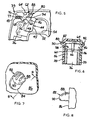
- a power circular saw designated generally by the numeral 20 is shown.
- Saw 20 has a housing assembly 22 in which is disposed a motor for powering a blade 24.
- Blade 24 is generally surrounded by an upper stationary guard 26 and a lower movable guard 28.
- Saw 20 also has a generally planar base or shoe 30 attached to stationary guard 26. Base 30 rests on the upper surface of the workpiece as the saw passes therethrough and is used to gauge the depth to which blade 24 cuts.
- Saw 20 further includes a rear trigger handle 32 and a forward brace handle 34.
- the trigger handle 32 has a power switch 36 mounted therein for operation by one hand of the saw user.
- the other hand of the saw user is positioned on brace handle 34 which allows the user to further control the saw as it passes through the workpiece.
- Trigger handle 32 has a generally hollow housing 38 which can be formed in a clamshell fashion by half sections 39. Housing 38 has a gripping portion 40 which fits within the palm of an operator during operation, and generally extends in an elongated direction along an axis 42, as best shown in Fig. 2. Power switch 36 is received within housing 38 and has a trigger 44 extending through an aperture 48 formed within housing 38 that allows actuation of the trigger by the index finger of an operator. More specifically, trigger 44 is configured with a finger-engaging surface 45 that accommodates the index finger of the hand of the operator gripping the handle. Trigger 44 is pivotally mounted about an axis 46 that is transverse to the elongated direction of handle portion 40 and to axis 42.
- Trigger 44 is actuated by an operator utilizing his or her index finger to rotate trigger 44 to the left in Fig. 5. As this is done, electrical contacts are made within switch 36 to connect the power supply of the saw with the saw motor to result in rotation of the blade. Trigger 44 is biased to its "off' position such that to actuate the switch and rotate it about axis 46 an operator must overcome the internal bias within switch 36. Trigger 44 can be pivotally mounted within housing 38 by a pin, trunnion or other suitable pivotal mounting arrangement.
- Trigger 44 is also received in a finger resting ring 52 extending outwardly from handle portion 40 and generally perpendicular to axis 42.
- Ring 52 serves to orient the index finger of a saw operator on trigger 44, and also provides a resting surface 54 upon which the index finger of a saw user can rest during operation while at the same time actuating the trigger. Ring 52 will help prevent an operator's index finger from slipping off of trigger 44 during operation because of the containment of the index finger within the aperture formed by the ring.
- the upper pivotal nature of trigger 44 and the positioning of the trigger within a finger support ring 52 provides a true "trigger" type operation which users often find comfortable and advantageous in selectively controlling the saw.
- Trigger 44 generally includes opposed spaced parallel sidewalls or flanges 56 which form a latch receiving space 58 therebetween, as best shown in Figs. 4-6.
- Trigger 44 has a locking pin 60 extending between flanges 56 at a location within housing 38 that is on the opposite side of trigger 44 from finger-engaging surface 45.
- Pin 60 rotates in the arc 61 indicated in Fig. 4 when trigger 44 is rotated.
- Pin 60 provides a locking engagement surface or abutment for engaging latch 62, as will be more fully described below.
- Latch 62 is generally L-shaped in nature and is pivotally mounted within housing 38 about an axis or pivot point 64 which is generally transverse to the elongated direction of handle portion 40 and axis 42. Latch 62 is pivotally mounted within housing 38 by any suitable means, such as a pivot pin, trunnion or other pivoting arrangement. Extending from axis 64 in a generally rearward direction is a locking leg or segment 66. Disposed on a rearward end of locking leg 66 is a generally arcuate abutment surface or cutout 68. Cutout 68 is used to engage pin 60 to secure trigger 44 in its locked position, as will be more fully described below. Leg 66 can have an inverted channel shape to reduce the weight associated with the latch member.
- a spring receiving area 72 Positioned on an upper surface 70 of locking arm 66 are a spring receiving area 72 and a spring maintaining pin 74. As best shown in Figs. 3 and 4, a coil compression spring is positioned about pin 74 and on area 72 and extends from arm 66 to a suitable receiving area 77 on an upper surface of housing 38. Spring 76 is used to bias latch 62 toward a locked position, as will be more fully described below.
- leg 78 Extending forwardly from pivot axis 64 is an actuating leg or segment 78.
- Leg 78 extends within housing 38 to a position that is forwardly of pivot axis 46 of trigger 44 along the elongated direction of portion 40.
- a locking lever 80 Located on a forward end of leg 78 is a locking lever 80 that extends transversely to the elongated direction of handle portion 40.
- lever 80 has two operator engaging sections 82 extending in opposite directions through oppositely disposed apertures 84 formed on the sidewalls 86 of housing 38. Segments 82 are the areas that are engaged by an operator to rotate latch 62 between a locked position, and an unlocked position, as will be more fully described below.
- Each segment 82 of lever 80 has an upper surface 88 that is sloped downwardly in a direction from the front of the saw toward the back of the saw, as best shown in Fig. 3. Still further, surface 88 is curved in a downwardly sloping arcuate fashion away from sidewall 86 to a lever end 90 (as best shown in Figs. 6-8). This arcuate curving is in a convex upwardly fashion. It is surface 88 and this downwardly sloping arcuate orientation from side wall 86 to end 90 that allows a user to easily slide his or her thumb off of the segment 82 after latch 62 has been actuated to its disengaged position and to position the thumb at a more comfortable location along the side of handle housing 38.
- segment 82 is actuated downwardly by the thumb of a user, it is desirable for the thumb to stay as close to sidewall 86 as possible.
- the sloping nature of segment 82 from side wall 86 to end 90 allows the thumb to slide over end surface 90 and resume its normal gripping position. End 90 is such that it is similar to a partial spherical surface which also aids the slide of the thumb off of segment 82.
- the thumb of the user may move slightly outwardly away from sidewall 86 as the thumb slides over end 90.
- the slope of surface 88, the distance segment 82 extends beyond surface 86, and the soft tissue associated with a user's thumb tip may be such that there is no noticeable outward movement of the thumb from side wall 86.
- some users may find it desirable to continue to rest their thumb on surface 88 during the entire cutting operation.
- the sloped surface 88 and its elimination of any sort of sharp edge associated with end 90 allows more user comfort if the user keeps his/her thumb on the segment.
- latch 62 is generally shown in a "locked” or “engaged” position. In this position, cutout 68 engages pin 60 of trigger 44, and is maintained thereon by the bias in coil spring 76. If a user attempts to rotate trigger 44 about trigger axis 46, latch 62 will prevent such rotation due to the engagement of abutting pin 60 and abutment cutout 68.
- An advantageous feature of latch 62 is the orientation such that the force vector of a user attempting to rotate trigger 44 at pin 60 extends directly through latch pivot axis 64. More specifically, the rotational arc of trigger 44 at pin 60 is shown in Fig. 4, as reference numeral 61.
- Pivot axis 64 of latch 62 is configured such that force vector 92 resulting from attempted actuation of trigger 44 extends directly through axis 64. Therefore, there are no force components being applied to latch 62 other than those directly through axis 64. As is apparent, this structure, because there are no other force vectors, helps prevent accidental disengagement of latch 62 and holds it firmly in its locked position even if substantial pressures are applied to trigger 44 by an operator.
- latch 62 is rotated to an "unlocked” and “disengaged” position by an operator pushing downwardly on upper surface 88 of either segment 82 to rotate leg 66 generally upwardly so that cutout 68 disengages pin 60.
- this rotation results in compression of spring 76, thus applying a downwardly biasing force to arm 66 that must be overcome by additional pressure on surface 88.
- a user begins rotation of trigger 44 using his or her index finger. As trigger 44 is rotated, pin 60 can pass adjacent a lower edge 94 of arm 60 until such time as electrical contact is made in switch 36 and the motor of saw 20 is actuated. As best shown in Figs.
- the downwardly sloping arcuate surface 88 from side wall 86 to end 90 allows an operator to easily slide his or her thumb over end 90 after latch 62 has been disengaged and thereafter rest comfortably along the side of housing 88 for further operation of the saw.
- the downward rotational direction of actuating leg 78 coincides with the downward pivot of a thumb, thus making the pivoting action of latch 62 a more natural occurrence for an operator.
- spring 76 will maintain contact between pin 60 and lower edge 94. After an operator is done cutting he or she simply releases trigger 44 and it returns to its "off' position via an internal spring bias. As it reaches its off position, pin 60 will again engage cutout 68 due to the bias of spring 76, and latch 62 will return automatically to its locked position. In order to reactuate trigger 44, an operator must again pivot latch 62 utilizing either of segments 82.
- the lockout mechanism in the present invention is advantageous for a number of reasons. First of all, the orientation of pivot point 64 of latch 62 such that force vector 92 of trigger 44 extends through such latch axis helps ensure that the latch will not accidentally disengage even when subjected to substantial force.
- actuating segments 82 and their sloped engaging surfaces 88 at a location that is forwardly of the location of the front portion of engaging surface 75 of trigger 44 ensures that the normal hand orientation, wherein the thumb is typically forward of the index finger during a gripping action, can be attained during the initial cutting operations of the saw, thus preventing unstable and awkward initial cutting operations.
- the rotational direction of latch 62 to its unlocked position in the same direction as the downward pivot of a user's thumb further allows easy, comfortable efficient operation by a user.
- the downwardly sloping arcuate upper surfaces 88 from sidewalls 86 toward ends 90 allow an operator to easily slide the thumb of the gripping hand over end 90 and off of lever 80 once the latch has been actuated.
- the dual oppositely extending segments 82 on both sides of the housing also allow easy uniform operation by either right-handed or left-handed operators.
- pivoting actions of both trigger 44 and latch 62 reduce the vulnerability to contamination and increased friction that is oftentimes present when sliding lockout mechanisms are utilized.
Claims (7)
- Un outil motorisé (20), comprenant :un boîtier (22) creux, définissant une poignée (32) avec une paroi extérieure ;un moteur, disposé dans le boîtier ;un interrupteur (36), comprenant un déclencheur (44), monté dans la poignée à pivotement autour d'un premier axe (46) pour actionner le moteur, l'interrupteur ayant une première butée de verrouillage (60),un verrou (62) placé de façon adjacente à l'interrupteur et monté à pivotement dans la poignée autour d'un deuxième axe (64) sensiblement parallèle au premier axe pour un déplacement dans une direction et dans l'autre, entre une position en prise et une position hors de prise, le verrou ayant une deuxième butée de verrouillage (68), pour venir en prise avec la première butée et empêcher l'interrupteur d'être actionné ; etun levier d'actionnement (80), pour déplacer le verrou (62) entre ses positions en prise et hors de prise,dans lequel le déclencheur (44), une fois pivoté pour venir en prise avec les première et deuxième butées, applique un vecteur de force coupant sensiblement le deuxième axe et dans lequel le verrou (62) est tourné à sa position hors de prise dans la même direction de pivotement que le sens de pivotement de descente du pouce d'un utilisateur,
caractérisé en ce que la paroi de poignée comprend une paire d'ouvertures (84) opposées et le levier d'actionnement (80) s'étend à travers les ouvertures (84). - Un outil motorisé tel que revendiqué à la revendication 1, dans lequel le verrou comprend une patte globalement "en forme de L", avec des premier et deuxième segments (66,78) connectés par un genou, le genou formant le point de pivotement du verrou.
- Un outil motorisé tel que revendiqué à la revendication 2 dans lequel le levier d'actionnement (80) s'étend transversalement par rapport à la patte et est disposé sur le premier segment, et le deuxième segment présente la deuxième butée disposée sur lui, le premier segment s'étendant dans une direction orientée vers l'avant du deuxième axe.
- Un outil motorisé tel que revendiqué à l'une quelconque des revendications 2 ou 3, dans lequel un ressort (76) est placé entre le deuxième segment et la paroi de poignée, pour solliciter le verrou dans un premier sens de rotation.
- Un outil motorisé tel que revendiqué à la revendication 4, dans lequel le déclencheur d'interrupteur (44) est supporté à pivotement pour un déplacement dans un deuxième sens de rotation, opposé au premier sens de rotation.
- Un outil motorisé tel que revendiqué à l'une quelconque des revendications antérieures, dans lequel :la paroi de poignée présente une ouverture (84) ;le verrou présente un levier d'actionnement (80) s'étendant à travers l'ouverture, le levier ayant une surface (88) pour être mise en prise par un pouce d'un utilisateur final, la surface étant inclinée vers le bas dans une direction de déplacement du pouce de l'utilisateur, lors du déplacement du verrou d'une position en prise à une position hors de prise.
- Un outil motorisé tel que revendiqué à l'une quelconque des revendications précédentes, comprenant en outre : un organe support (54) placé directement au-dessous de l'interrupteur, de manière que l'index de l'utilisateur puisse être logé par l'interrupteur, l'organe support fournissant une surface de repos à l'index durant le fonctionnement.
Priority Applications (2)
| Application Number | Priority Date | Filing Date | Title |
|---|---|---|---|
| EP06111208A EP1670011B1 (fr) | 1998-08-14 | 1999-08-11 | Dispositif de verrouillage pour un outil motorisé |
| EP05018447A EP1605482B1 (fr) | 1998-08-14 | 1999-08-11 | Mécanisme de blocage pour outil à moteur |
Applications Claiming Priority (2)
| Application Number | Priority Date | Filing Date | Title |
|---|---|---|---|
| US133846 | 1998-08-14 | ||
| US09/133,846 US6057518A (en) | 1998-08-14 | 1998-08-14 | Lockout mechanism for power tool |
Related Child Applications (2)
| Application Number | Title | Priority Date | Filing Date |
|---|---|---|---|
| EP05018447A Division EP1605482B1 (fr) | 1998-08-14 | 1999-08-11 | Mécanisme de blocage pour outil à moteur |
| EP06111208A Division EP1670011B1 (fr) | 1998-08-14 | 1999-08-11 | Dispositif de verrouillage pour un outil motorisé |
Publications (3)
| Publication Number | Publication Date |
|---|---|
| EP0982745A2 EP0982745A2 (fr) | 2000-03-01 |
| EP0982745A3 EP0982745A3 (fr) | 2000-08-16 |
| EP0982745B1 true EP0982745B1 (fr) | 2006-10-18 |
Family
ID=22460558
Family Applications (3)
| Application Number | Title | Priority Date | Filing Date |
|---|---|---|---|
| EP05018447A Expired - Lifetime EP1605482B1 (fr) | 1998-08-14 | 1999-08-11 | Mécanisme de blocage pour outil à moteur |
| EP06111208A Expired - Lifetime EP1670011B1 (fr) | 1998-08-14 | 1999-08-11 | Dispositif de verrouillage pour un outil motorisé |
| EP99306355A Expired - Lifetime EP0982745B1 (fr) | 1998-08-14 | 1999-08-11 | Dispositif de verrouillage pour un outil motorisé |
Family Applications Before (2)
| Application Number | Title | Priority Date | Filing Date |
|---|---|---|---|
| EP05018447A Expired - Lifetime EP1605482B1 (fr) | 1998-08-14 | 1999-08-11 | Mécanisme de blocage pour outil à moteur |
| EP06111208A Expired - Lifetime EP1670011B1 (fr) | 1998-08-14 | 1999-08-11 | Dispositif de verrouillage pour un outil motorisé |
Country Status (8)
| Country | Link |
|---|---|
| US (4) | US6057518A (fr) |
| EP (3) | EP1605482B1 (fr) |
| JP (1) | JP4786774B2 (fr) |
| AT (3) | ATE343214T1 (fr) |
| DE (3) | DE69937377T2 (fr) |
| DK (1) | DK1605482T3 (fr) |
| ES (1) | ES2293450T3 (fr) |
| PT (1) | PT1605482E (fr) |
Families Citing this family (37)
| Publication number | Priority date | Publication date | Assignee | Title |
|---|---|---|---|---|
| US6057518A (en) * | 1998-08-14 | 2000-05-02 | Black & Decker, Inc. | Lockout mechanism for power tool |
| US6091035A (en) * | 1998-08-14 | 2000-07-18 | Black & Decker, Inc. | Lockout mechanism for power tool |
| JP2000233383A (ja) * | 1999-02-12 | 2000-08-29 | Makita Corp | 電動工具のスイッチ機構 |
| US6274828B1 (en) * | 2000-02-22 | 2001-08-14 | Defond Manufacturing Limited | On-off switch with off position locking actuator |
| DE10040326A1 (de) * | 2000-08-17 | 2002-02-28 | Hilti Ag | Feststelleinrichtung für handgeführte Elektrowerkzeuge |
| JP3961755B2 (ja) * | 2000-09-18 | 2007-08-22 | Idec株式会社 | グリップ式スイッチ装置 |
| DE20104536U1 (de) * | 2001-03-16 | 2001-05-23 | Stihl Maschf Andreas | Handgeführtes, tragbares Arbeitsgerät mit Daumenstützen |
| AU2002324688A1 (en) | 2001-08-10 | 2003-02-24 | Shakti Systems, Inc. | Logic state transition sensor circuit |
| US6653584B1 (en) * | 2002-05-24 | 2003-11-25 | Rexon Co., Ltd. | Successive switch device of a slot cutting machine |
| US6987244B2 (en) * | 2002-07-31 | 2006-01-17 | Illinois Tool Works Inc. | Self-contained locking trigger assembly and systems which incorporate the assembly |
| US6753490B2 (en) * | 2002-10-16 | 2004-06-22 | S-B Power Tool Corporation | Ambidextrous switch lockout system |
| GB2395460B8 (en) * | 2002-11-22 | 2013-02-06 | Bosch Gmbh Robert | Electric hand tool machine |
| US6930262B2 (en) * | 2003-06-30 | 2005-08-16 | Wy Peron Lee | Safety switch box for saw machine |
| EP1589550A1 (fr) * | 2004-04-20 | 2005-10-26 | GMCA PTY Ltd | Mécanisme de commutation |
| CA2506878C (fr) * | 2004-05-10 | 2011-11-22 | Gary Anderson | Verrou d'outil pneumatique |
| CA2506876C (fr) * | 2004-05-10 | 2012-11-20 | Gary Anderson | Dispositif de verrouillage d'outil electrique |
| US7750509B2 (en) * | 2004-05-10 | 2010-07-06 | Gary Anderson | Power tool lockdown device |
| TWM301736U (en) * | 2006-06-05 | 2006-12-01 | Mobiletron Electronics Co Ltd | Electrical tool |
| DE102006000316A1 (de) * | 2006-06-29 | 2008-01-03 | Hilti Ag | Haupthandgriff mit Sicherungsverriegelung |
| US7476821B1 (en) * | 2007-07-24 | 2009-01-13 | Defond Components Limited | Trigger mechanism |
| JP5148297B2 (ja) * | 2008-01-10 | 2013-02-20 | 株式会社マキタ | マルノコ |
| GB0812274D0 (en) * | 2008-07-04 | 2008-08-13 | Black & Decker Inc | Switch mechanism for a power cutter |
| US8198560B2 (en) * | 2009-01-09 | 2012-06-12 | Makita Corporation | Switch devices for power tools |
| US8393835B2 (en) * | 2009-06-16 | 2013-03-12 | Robert Bosch Gmbh | Detachable operating handle for a power tool |
| ITTV20090136A1 (it) * | 2009-06-26 | 2010-12-27 | Saccon Srl | Dispositivo di sicurezza meccanico per lo sbloccamento selettivo d'una leva di comando con tirante a cavo per attrezzature veicolate e leva di comando con dispositivo di sicurezza per attrezzature veicolate |
| US8937259B2 (en) | 2009-10-13 | 2015-01-20 | Barton L. Garvin | Universal electrical circuit breaker locking device |
| US8598477B2 (en) | 2009-10-13 | 2013-12-03 | Barton L. Garvin | Universal switch restraint device |
| US9149923B2 (en) | 2010-11-09 | 2015-10-06 | Black & Decker Inc. | Oscillating tools and accessories |
| US8723060B2 (en) * | 2011-12-21 | 2014-05-13 | Robert Bosch Tool Corporation | Method and mechanism for power tool lock-off |
| US8872049B2 (en) | 2012-04-18 | 2014-10-28 | Milwaukee Electric Tool Corporation | Trigger lock-on lock-off mechanism |
| CN105392587B (zh) | 2012-12-11 | 2017-09-15 | 罗伯特·博世有限公司 | 具有发光元件系统的圆锯 |
| US10014128B2 (en) * | 2013-12-17 | 2018-07-03 | Robert Bosch Tool Corporation | Portable power tool with trigger switch, trigger release and lock-on mechanism combination |
| GB2546733B (en) * | 2016-01-22 | 2018-07-04 | Dyson Technology Ltd | Domestic appliance and part thereof |
| US20180093335A1 (en) | 2016-10-04 | 2018-04-05 | Tti (Macao Commercial Offshore) Limited | Trigger lock for a miter saw |
| JP7167490B2 (ja) * | 2018-05-31 | 2022-11-09 | 工機ホールディングス株式会社 | 電動工具 |
| TWM605270U (zh) * | 2020-06-04 | 2020-12-11 | 勞朋企業有限公司 | 用於瓦斯燃燒器之安全開關 |
| TWI745198B (zh) * | 2020-12-21 | 2021-11-01 | 力山工業股份有限公司 | 具安全裝置的可收合鋸切機 |
Family Cites Families (63)
| Publication number | Priority date | Publication date | Assignee | Title |
|---|---|---|---|---|
| US30270A (en) * | 1860-10-02 | Hew-cleaner | ||
| US1929662A (en) * | 1930-08-16 | 1933-10-10 | Wappat Inc | Motor driven tool switch |
| US3194084A (en) * | 1963-01-21 | 1965-07-13 | Black & Decker Mfg Co | Trigger locking means for hand-portable power-operated device |
| US3331406A (en) | 1964-03-03 | 1967-07-18 | Joseph C Christophel | Radial saw |
| US3383943A (en) | 1966-07-08 | 1968-05-21 | Cutler Hammer Inc | All-speed lever lock |
| US3626118A (en) * | 1966-11-14 | 1971-12-07 | Harold R Botefuhr | Radial arm saw with a depressible key for unlocking a switch-actuating trigger |
| US3422296A (en) | 1967-01-03 | 1969-01-14 | Emerson Electric Co | Interlock reversing switch |
| US3461556A (en) * | 1967-07-10 | 1969-08-19 | Sunbeam Corp | Trigger switch for electric appliance |
| US3376402A (en) | 1967-09-25 | 1968-04-02 | Black & Decker Mfg Co | Reversible electric switch with laterally extending reversing member for use in portable electric tool or appliance |
| US3579002A (en) | 1970-03-31 | 1971-05-18 | Black & Decker Mfg Co | Reversing switch for power tools |
| US3746815A (en) | 1971-11-03 | 1973-07-17 | Cutler Hammer Inc | Off locking trigger switches |
| US3780246A (en) * | 1972-08-22 | 1973-12-18 | Black & Decker Mfg Co | Hand-operated tool with switch actuator having three-position lock-off assembly |
| DE2254554C3 (de) | 1972-11-08 | 1979-08-30 | Licentia Patent-Verwaltungs-Gmbh, 6000 Frankfurt | Einschalter für eine elektromotorisch angetriebene Handwerkzeugmaschine |
| USRE30270E (en) | 1972-12-18 | 1980-05-06 | Eaton Corporation | Off locking in-line trigger switch |
| DE7321450U (de) | 1973-06-08 | 1973-09-06 | Metabowerke Kg | Schalter für ein elektromotorisch betriebenes Handwerkzeug |
| US3873796A (en) * | 1973-07-06 | 1975-03-25 | Black & Decker Mfg Co | Trigger mechanism for hand-operated power device including independently operable locking devices providing automatic lock off and manual lock-on operation |
| JPS5078998A (fr) * | 1973-11-15 | 1975-06-27 | ||
| US3973179A (en) * | 1974-08-23 | 1976-08-03 | The Black And Decker Manufacturing Company | Modular cordless tools |
| US3952239A (en) * | 1974-08-23 | 1976-04-20 | The Black And Decker Manufacturing Company | Modular cordless tools |
| US3971906A (en) * | 1974-11-01 | 1976-07-27 | Lucerne Products, Inc. | Trigger-lock control |
| DE2601269A1 (de) | 1976-01-15 | 1977-07-21 | Streicher Emide Metall | Haushaltsschneidemaschine |
| US4122320A (en) * | 1976-08-16 | 1978-10-24 | Disston, Inc. | Hand-operated double-acting trigger switch |
| US4135068A (en) | 1976-09-13 | 1979-01-16 | Bowen Tools, Inc. | Dead man safety assembly |
| JPS567053Y2 (fr) | 1977-11-15 | 1981-02-16 | ||
| US4196343A (en) * | 1978-03-02 | 1980-04-01 | C.A.H., Inc. | Hair dryer |
| FR2454171A1 (fr) | 1979-04-13 | 1980-11-07 | Telemecanique Electrique | Dispositif de verrouillage pour deux boutons-poussoirs |
| DE3007304A1 (de) | 1980-02-27 | 1981-09-03 | Marquardt Gmbh, 7201 Rietheim-Weilheim | Elektrischer schalter, insbesondere fuer ein elektrisches handwerkzeug |
| US4276459A (en) * | 1980-06-16 | 1981-06-30 | Ingersoll-Rand Company | Paddle switch safety button |
| US4449062A (en) * | 1980-09-15 | 1984-05-15 | Black & Decker Inc. | Safety arrangement for a powered tool or implement |
| US4365141A (en) * | 1981-01-05 | 1982-12-21 | Jerdon Industries, Inc. | Hair dryer |
| DE3104733C3 (de) | 1981-02-11 | 1997-01-09 | Reich Maschf Gmbh Karl | Schalter für Elektrowerkzeuge |
| DE3342412A1 (de) | 1983-11-24 | 1985-06-05 | Black & Decker Inc., Newark, Del. | Schalteranordnung fuer den drehrichtungsumschalter eines elektrowerkzeugs, insbesondere einer bohr- oder schlagbohrmaschine |
| DE3731079A1 (de) | 1987-09-16 | 1989-03-30 | Metabowerke Kg | Elektrohandwerkzeug mit einem universalmotor mit rechts- und linkslauf |
| US4934494A (en) * | 1988-03-30 | 1990-06-19 | Makita Electric Works, Ltd. | Combined locking mechanism and switch especially for power tools |
| US4864083A (en) | 1988-04-15 | 1989-09-05 | Lucerne Products, Inc. | Reversing switch |
| US4900881A (en) | 1988-10-24 | 1990-02-13 | Breuer Electric Mfg. Co. | Safety interlock for floor maintenance machine and method |
| JPH02137723U (fr) | 1989-04-21 | 1990-11-16 | ||
| JPH0832396B2 (ja) * | 1989-05-17 | 1996-03-29 | 株式会社マキタ | 携帯用電動工具 |
| DE8908924U1 (fr) | 1989-07-22 | 1989-09-14 | Gardena Kress + Kastner Gmbh, 7900 Ulm, De | |
| DE4007030A1 (de) * | 1990-03-02 | 1991-09-05 | Black & Decker Inc | Kraftgetriebene handwerkzeugmaschine mit einem rotierend angetriebenen werkzeug |
| DE4023101A1 (de) * | 1990-07-20 | 1992-01-23 | Metabowerke Kg | Elektrowerkzeug mit einer schalterverriegelung |
| DE4120874C2 (de) | 1991-06-21 | 2002-02-07 | Stihl Maschf Andreas | Gerätegehäuse für ein Arbeitsgerät, insbesondere eine Motorkettensäge |
| US5310259A (en) | 1993-02-02 | 1994-05-10 | Black & Decker Inc. | Mixer with lockout device for power boost switch |
| DE4309033C2 (de) | 1993-03-20 | 1999-11-25 | Braun Gmbh | Sicherheitsschaltvorrichtung für elektrische Geräte |
| US5440089A (en) | 1993-05-07 | 1995-08-08 | General Binding Corporation | Foot/table switch lockout for electric punches |
| DE4407418C2 (de) * | 1994-03-03 | 1998-02-19 | Black & Decker Inc | Schalteranordnung, insbesondere für eine Oberfräse |
| JP3572665B2 (ja) * | 1994-06-10 | 2004-10-06 | 日立工機株式会社 | 携帯用電動工具 |
| DE19522218B4 (de) | 1994-06-23 | 2010-11-11 | Fa. Andreas Stihl | Griffanordnung für eine Motorkettensäge |
| US5629679A (en) * | 1994-12-15 | 1997-05-13 | Cranford; Richard | Personal security device |
| US5483727A (en) * | 1995-03-02 | 1996-01-16 | P&F Brother Industrial Corporation | Operating handle for a cutting device |
| JP2852217B2 (ja) | 1995-10-26 | 1999-01-27 | リョービ株式会社 | トリガースイッチ |
| US5577600A (en) * | 1995-11-21 | 1996-11-26 | Emerson Electric Co. | Switch lock-out device for power tool |
| GB9524333D0 (en) | 1995-11-28 | 1996-01-31 | Black & Decker Inc | Lock-on, lock-off switch |
| DE19546328B4 (de) | 1995-12-12 | 2007-12-13 | Robert Bosch Gmbh | Handwerkzeugmaschine mit einem drehbaren Handgriff |
| JP2977076B2 (ja) | 1996-03-01 | 1999-11-10 | リョービ株式会社 | 電動工具のスイッチ機構 |
| US5638945A (en) * | 1996-06-10 | 1997-06-17 | Ryobi North America, Inc. | Locking trigger mechanism for a portable power tool |
| DE19745100B4 (de) | 1996-10-22 | 2007-01-04 | Marquardt Gmbh | Elektrischer Schalter |
| US5778747A (en) | 1996-11-21 | 1998-07-14 | Rexon Industrial Corp., Ltd. | Power saw having an ergonomically-designed handle and safety switch |
| JPH11347968A (ja) * | 1998-06-09 | 1999-12-21 | Makita Corp | 電動工具のスイッチ機構 |
| US5969312A (en) | 1998-06-24 | 1999-10-19 | S-B Power Tool Company | Ambidextrous powers-switch lock-out mechanism |
| US6057518A (en) * | 1998-08-14 | 2000-05-02 | Black & Decker, Inc. | Lockout mechanism for power tool |
| US6091035A (en) * | 1998-08-14 | 2000-07-18 | Black & Decker, Inc. | Lockout mechanism for power tool |
| JP2000233383A (ja) * | 1999-02-12 | 2000-08-29 | Makita Corp | 電動工具のスイッチ機構 |
-
1998
- 1998-08-14 US US09/133,846 patent/US6057518A/en not_active Expired - Lifetime
-
1999
- 1999-08-11 DE DE69937377T patent/DE69937377T2/de not_active Expired - Lifetime
- 1999-08-11 EP EP05018447A patent/EP1605482B1/fr not_active Expired - Lifetime
- 1999-08-11 EP EP06111208A patent/EP1670011B1/fr not_active Expired - Lifetime
- 1999-08-11 AT AT99306355T patent/ATE343214T1/de not_active IP Right Cessation
- 1999-08-11 DE DE69933626T patent/DE69933626T2/de not_active Expired - Lifetime
- 1999-08-11 AT AT05018447T patent/ATE376250T1/de not_active IP Right Cessation
- 1999-08-11 PT PT05018447T patent/PT1605482E/pt unknown
- 1999-08-11 EP EP99306355A patent/EP0982745B1/fr not_active Expired - Lifetime
- 1999-08-11 DK DK05018447T patent/DK1605482T3/da active
- 1999-08-11 DE DE69939718T patent/DE69939718D1/de not_active Expired - Lifetime
- 1999-08-11 AT AT06111208T patent/ATE410778T1/de not_active IP Right Cessation
- 1999-08-11 ES ES05018447T patent/ES2293450T3/es not_active Expired - Lifetime
- 1999-08-16 JP JP23002199A patent/JP4786774B2/ja not_active Expired - Fee Related
-
2000
- 2000-03-14 US US09/524,867 patent/US6340802B1/en not_active Expired - Lifetime
-
2002
- 2002-01-18 US US10/051,422 patent/US6538218B2/en not_active Expired - Fee Related
-
2003
- 2003-03-04 US US10/379,120 patent/US6861598B2/en not_active Expired - Fee Related
Also Published As
| Publication number | Publication date |
|---|---|
| US20030136652A1 (en) | 2003-07-24 |
| DE69933626D1 (de) | 2006-11-30 |
| EP0982745A2 (fr) | 2000-03-01 |
| DE69937377D1 (de) | 2007-11-29 |
| DE69937377T2 (de) | 2008-07-17 |
| EP1670011B1 (fr) | 2008-10-08 |
| US20020056618A1 (en) | 2002-05-16 |
| EP1670011A1 (fr) | 2006-06-14 |
| US6057518A (en) | 2000-05-02 |
| DE69933626T2 (de) | 2007-08-23 |
| ES2293450T3 (es) | 2008-03-16 |
| US6538218B2 (en) | 2003-03-25 |
| EP1605482B1 (fr) | 2007-10-17 |
| ATE343214T1 (de) | 2006-11-15 |
| EP1605482A1 (fr) | 2005-12-14 |
| ATE410778T1 (de) | 2008-10-15 |
| US6340802B1 (en) | 2002-01-22 |
| JP4786774B2 (ja) | 2011-10-05 |
| US6861598B2 (en) | 2005-03-01 |
| DE69939718D1 (de) | 2008-11-20 |
| JP2000061867A (ja) | 2000-02-29 |
| ATE376250T1 (de) | 2007-11-15 |
| EP0982745A3 (fr) | 2000-08-16 |
| PT1605482E (pt) | 2008-01-28 |
| DK1605482T3 (da) | 2008-02-11 |
Similar Documents
| Publication | Publication Date | Title |
|---|---|---|
| EP0982745B1 (fr) | Dispositif de verrouillage pour un outil motorisé | |
| US6288350B1 (en) | Lockout mechanism for power tool | |
| US5638945A (en) | Locking trigger mechanism for a portable power tool | |
| US7739799B2 (en) | Combination utility and sporting knife | |
| EP2248413B1 (fr) | Taille-haie avec poignée arrière rotative | |
| US5577600A (en) | Switch lock-out device for power tool | |
| EP2285535B1 (fr) | Dispositif électrique doté d'un mécanisme marche-arrêt | |
| US6805208B2 (en) | Switch lock-off mechanism for power tools | |
| US6610946B2 (en) | Actuation mechanism for a power tool | |
| US7015409B2 (en) | Power tool trigger | |
| JPH1124771A (ja) | 作業機の操作レバー装置 | |
| WO1999058302A1 (fr) | Couteau pliant |
Legal Events
| Date | Code | Title | Description |
|---|---|---|---|
| PUAI | Public reference made under article 153(3) epc to a published international application that has entered the european phase |
Free format text: ORIGINAL CODE: 0009012 |
|
| AK | Designated contracting states |
Kind code of ref document: A2 Designated state(s): AT BE CH CY DE DK ES FI FR GB GR IE IT LI LU MC NL PT SE |
|
| AX | Request for extension of the european patent |
Free format text: AL;LT;LV;MK;RO;SI |
|
| PUAL | Search report despatched |
Free format text: ORIGINAL CODE: 0009013 |
|
| AK | Designated contracting states |
Kind code of ref document: A3 Designated state(s): AT BE CH CY DE DK ES FI FR GB GR IE IT LI LU MC NL PT SE |
|
| AX | Request for extension of the european patent |
Free format text: AL;LT;LV;MK;RO;SI |
|
| RIC1 | Information provided on ipc code assigned before grant |
Free format text: 7H 01H 13/08 A, 7H 01H 3/20 B |
|
| 17P | Request for examination filed |
Effective date: 20010130 |
|
| AKX | Designation fees paid |
Free format text: AT BE CH CY DE DK ES FI FR GB GR IE IT LI LU MC NL PT SE |
|
| 17Q | First examination report despatched |
Effective date: 20050304 |
|
| GRAP | Despatch of communication of intention to grant a patent |
Free format text: ORIGINAL CODE: EPIDOSNIGR1 |
|
| GRAS | Grant fee paid |
Free format text: ORIGINAL CODE: EPIDOSNIGR3 |
|
| GRAA | (expected) grant |
Free format text: ORIGINAL CODE: 0009210 |
|
| AK | Designated contracting states |
Kind code of ref document: B1 Designated state(s): AT BE CH CY DE DK ES FI FR GB GR IE IT LI LU MC NL PT SE |
|
| PG25 | Lapsed in a contracting state [announced via postgrant information from national office to epo] |
Ref country code: NL Free format text: LAPSE BECAUSE OF FAILURE TO SUBMIT A TRANSLATION OF THE DESCRIPTION OR TO PAY THE FEE WITHIN THE PRESCRIBED TIME-LIMIT Effective date: 20061018 Ref country code: LI Free format text: LAPSE BECAUSE OF FAILURE TO SUBMIT A TRANSLATION OF THE DESCRIPTION OR TO PAY THE FEE WITHIN THE PRESCRIBED TIME-LIMIT Effective date: 20061018 Ref country code: FI Free format text: LAPSE BECAUSE OF FAILURE TO SUBMIT A TRANSLATION OF THE DESCRIPTION OR TO PAY THE FEE WITHIN THE PRESCRIBED TIME-LIMIT Effective date: 20061018 Ref country code: CH Free format text: LAPSE BECAUSE OF FAILURE TO SUBMIT A TRANSLATION OF THE DESCRIPTION OR TO PAY THE FEE WITHIN THE PRESCRIBED TIME-LIMIT Effective date: 20061018 Ref country code: BE Free format text: LAPSE BECAUSE OF FAILURE TO SUBMIT A TRANSLATION OF THE DESCRIPTION OR TO PAY THE FEE WITHIN THE PRESCRIBED TIME-LIMIT Effective date: 20061018 Ref country code: AT Free format text: LAPSE BECAUSE OF FAILURE TO SUBMIT A TRANSLATION OF THE DESCRIPTION OR TO PAY THE FEE WITHIN THE PRESCRIBED TIME-LIMIT Effective date: 20061018 |
|
| REG | Reference to a national code |
Ref country code: GB Ref legal event code: FG4D |
|
| REG | Reference to a national code |
Ref country code: IE Ref legal event code: FG4D Ref country code: CH Ref legal event code: EP |
|
| REF | Corresponds to: |
Ref document number: 69933626 Country of ref document: DE Date of ref document: 20061130 Kind code of ref document: P |
|
| PG25 | Lapsed in a contracting state [announced via postgrant information from national office to epo] |
Ref country code: DK Free format text: LAPSE BECAUSE OF FAILURE TO SUBMIT A TRANSLATION OF THE DESCRIPTION OR TO PAY THE FEE WITHIN THE PRESCRIBED TIME-LIMIT Effective date: 20070118 |
|
| PG25 | Lapsed in a contracting state [announced via postgrant information from national office to epo] |
Ref country code: ES Free format text: LAPSE BECAUSE OF FAILURE TO SUBMIT A TRANSLATION OF THE DESCRIPTION OR TO PAY THE FEE WITHIN THE PRESCRIBED TIME-LIMIT Effective date: 20070129 |
|
| REG | Reference to a national code |
Ref country code: SE Ref legal event code: TRGR |
|
| PG25 | Lapsed in a contracting state [announced via postgrant information from national office to epo] |
Ref country code: PT Free format text: LAPSE BECAUSE OF FAILURE TO SUBMIT A TRANSLATION OF THE DESCRIPTION OR TO PAY THE FEE WITHIN THE PRESCRIBED TIME-LIMIT Effective date: 20070319 |
|
| NLV1 | Nl: lapsed or annulled due to failure to fulfill the requirements of art. 29p and 29m of the patents act | ||
| ET | Fr: translation filed | ||
| REG | Reference to a national code |
Ref country code: CH Ref legal event code: PL |
|
| PLBE | No opposition filed within time limit |
Free format text: ORIGINAL CODE: 0009261 |
|
| STAA | Information on the status of an ep patent application or granted ep patent |
Free format text: STATUS: NO OPPOSITION FILED WITHIN TIME LIMIT |
|
| 26N | No opposition filed |
Effective date: 20070719 |
|
| PG25 | Lapsed in a contracting state [announced via postgrant information from national office to epo] |
Ref country code: MC Free format text: LAPSE BECAUSE OF NON-PAYMENT OF DUE FEES Effective date: 20070831 Ref country code: GR Free format text: LAPSE BECAUSE OF FAILURE TO SUBMIT A TRANSLATION OF THE DESCRIPTION OR TO PAY THE FEE WITHIN THE PRESCRIBED TIME-LIMIT Effective date: 20070119 |
|
| PG25 | Lapsed in a contracting state [announced via postgrant information from national office to epo] |
Ref country code: IE Free format text: LAPSE BECAUSE OF NON-PAYMENT OF DUE FEES Effective date: 20070813 |
|
| PG25 | Lapsed in a contracting state [announced via postgrant information from national office to epo] |
Ref country code: LU Free format text: LAPSE BECAUSE OF NON-PAYMENT OF DUE FEES Effective date: 20070811 Ref country code: CY Free format text: LAPSE BECAUSE OF FAILURE TO SUBMIT A TRANSLATION OF THE DESCRIPTION OR TO PAY THE FEE WITHIN THE PRESCRIBED TIME-LIMIT Effective date: 20061018 |
|
| PGFP | Annual fee paid to national office [announced via postgrant information from national office to epo] |
Ref country code: GB Payment date: 20120828 Year of fee payment: 14 Ref country code: SE Payment date: 20120829 Year of fee payment: 14 |
|
| PGFP | Annual fee paid to national office [announced via postgrant information from national office to epo] |
Ref country code: FR Payment date: 20120830 Year of fee payment: 14 Ref country code: IT Payment date: 20120823 Year of fee payment: 14 |
|
| PGFP | Annual fee paid to national office [announced via postgrant information from national office to epo] |
Ref country code: DE Payment date: 20130828 Year of fee payment: 15 |
|
| REG | Reference to a national code |
Ref country code: SE Ref legal event code: EUG |
|
| GBPC | Gb: european patent ceased through non-payment of renewal fee |
Effective date: 20130811 |
|
| PG25 | Lapsed in a contracting state [announced via postgrant information from national office to epo] |
Ref country code: SE Free format text: LAPSE BECAUSE OF NON-PAYMENT OF DUE FEES Effective date: 20130812 |
|
| REG | Reference to a national code |
Ref country code: FR Ref legal event code: ST Effective date: 20140430 |
|
| PG25 | Lapsed in a contracting state [announced via postgrant information from national office to epo] |
Ref country code: IT Free format text: LAPSE BECAUSE OF NON-PAYMENT OF DUE FEES Effective date: 20130811 |
|
| PG25 | Lapsed in a contracting state [announced via postgrant information from national office to epo] |
Ref country code: GB Free format text: LAPSE BECAUSE OF NON-PAYMENT OF DUE FEES Effective date: 20130811 |
|
| PG25 | Lapsed in a contracting state [announced via postgrant information from national office to epo] |
Ref country code: FR Free format text: LAPSE BECAUSE OF NON-PAYMENT OF DUE FEES Effective date: 20130902 |
|
| REG | Reference to a national code |
Ref country code: DE Ref legal event code: R119 Ref document number: 69933626 Country of ref document: DE |
|
| REG | Reference to a national code |
Ref country code: DE Ref legal event code: R119 Ref document number: 69933626 Country of ref document: DE Effective date: 20150303 |
|
| PG25 | Lapsed in a contracting state [announced via postgrant information from national office to epo] |
Ref country code: DE Free format text: LAPSE BECAUSE OF NON-PAYMENT OF DUE FEES Effective date: 20150303 |