EP0978418B1 - Vorrichtung zum Einbau in einen Kraftwagen mit einem Ausziehteil - Google Patents
Vorrichtung zum Einbau in einen Kraftwagen mit einem Ausziehteil Download PDFInfo
- Publication number
- EP0978418B1 EP0978418B1 EP99112921A EP99112921A EP0978418B1 EP 0978418 B1 EP0978418 B1 EP 0978418B1 EP 99112921 A EP99112921 A EP 99112921A EP 99112921 A EP99112921 A EP 99112921A EP 0978418 B1 EP0978418 B1 EP 0978418B1
- Authority
- EP
- European Patent Office
- Prior art keywords
- latch
- drawer
- push
- out part
- pop
- Prior art date
- Legal status (The legal status is an assumption and is not a legal conclusion. Google has not performed a legal analysis and makes no representation as to the accuracy of the status listed.)
- Expired - Lifetime
Links
- 230000001133 acceleration Effects 0.000 claims description 11
- 238000009434 installation Methods 0.000 claims description 4
- 235000013361 beverage Nutrition 0.000 description 3
- 208000027418 Wounds and injury Diseases 0.000 description 2
- 230000006378 damage Effects 0.000 description 2
- 238000013016 damping Methods 0.000 description 2
- 238000006073 displacement reaction Methods 0.000 description 2
- 208000014674 injury Diseases 0.000 description 2
- CDBYLPFSWZWCQE-UHFFFAOYSA-L Sodium Carbonate Chemical compound [Na+].[Na+].[O-]C([O-])=O CDBYLPFSWZWCQE-UHFFFAOYSA-L 0.000 description 1
- 230000002238 attenuated effect Effects 0.000 description 1
- 230000037431 insertion Effects 0.000 description 1
- 238000003780 insertion Methods 0.000 description 1
- 239000002991 molded plastic Substances 0.000 description 1
- 239000004033 plastic Substances 0.000 description 1
- 230000000979 retarding effect Effects 0.000 description 1
Images


Classifications
-
- E—FIXED CONSTRUCTIONS
- E05—LOCKS; KEYS; WINDOW OR DOOR FITTINGS; SAFES
- E05B—LOCKS; ACCESSORIES THEREFOR; HANDCUFFS
- E05B77/00—Vehicle locks characterised by special functions or purposes
- E05B77/02—Vehicle locks characterised by special functions or purposes for accident situations
- E05B77/04—Preventing unwanted lock actuation, e.g. unlatching, at the moment of collision
- E05B77/06—Preventing unwanted lock actuation, e.g. unlatching, at the moment of collision by means of inertial forces
-
- B—PERFORMING OPERATIONS; TRANSPORTING
- B60—VEHICLES IN GENERAL
- B60R—VEHICLES, VEHICLE FITTINGS, OR VEHICLE PARTS, NOT OTHERWISE PROVIDED FOR
- B60R7/00—Stowing or holding appliances inside vehicle primarily intended for personal property smaller than suit-cases, e.g. travelling articles, or maps
- B60R7/08—Disposition of racks, clips, holders, containers or the like for supporting specific articles
-
- B—PERFORMING OPERATIONS; TRANSPORTING
- B60—VEHICLES IN GENERAL
- B60R—VEHICLES, VEHICLE FITTINGS, OR VEHICLE PARTS, NOT OTHERWISE PROVIDED FOR
- B60R7/00—Stowing or holding appliances inside vehicle primarily intended for personal property smaller than suit-cases, e.g. travelling articles, or maps
- B60R7/04—Stowing or holding appliances inside vehicle primarily intended for personal property smaller than suit-cases, e.g. travelling articles, or maps in driver or passenger space, e.g. using racks
- B60R7/06—Stowing or holding appliances inside vehicle primarily intended for personal property smaller than suit-cases, e.g. travelling articles, or maps in driver or passenger space, e.g. using racks mounted on or below dashboards
Definitions
- the invention relates to a device for installation in a motor vehicle, with an extractable part, according to the preamble of claim 1.
- Such a pull-out may for example be a storage compartment, the art a drawer by pulling out of a basic position in one Use position is movable. In the basic position, the pull-out part closes in the substantially flush with, for example, a dashboard of the motor vehicle in the use position, the pull-out protrudes into a passenger compartment. It can For example, a swivel or other guide be provided to To be able to move the pull-out part from the basic to the use position.
- the pull-out can, for example, a holder for a beverage container such as a soda can, a beverage cup or the like. Be.
- EP-A-0 525 811 is a generic device with a downwardly pivotable flap Lockable storage compartment known, which can be arranged on a ceiling of a Motor vehicle is provided.
- the flap forms a bottom of the storage compartment.
- the Flap is closed by a so-called push-push locking device held by pushing the flap up into the storage compartment is unlockable.
- the known storage compartment has a safety locking device with a pivotally mounted latch on, the has an angled foot at its free end.
- the bolt pivots with his foot against the force of a Return spring element in a recess of the flap and prevents in that the flap move into the storage compartment and thereby the Push-push locking device can unlock.
- the flap unlocks and opens.
- a holder for beverage containers which belongs to Installation is provided in a motor vehicle.
- the holder has a drawer-like pull-out slide on, with a push-push locking device in a closed, retracted position is held.
- points the known holder a displaceable in the direction of insertion of the slider Ground up by inertial forces in an accident against the force of a person Return spring element is moved so that they push the push-locking device blocked, so that the latter can not unlock.
- the invention is based on the object, an extractable part in a motor vehicle in Case of an accident to prevent self-opening, with the opening Spend is meant from the basic position in the position of use.
- the device has a safety lock a latch on. Due to the inertia of the bolt arrives at a Rear-end collision, an impact of the motor vehicle on an obstacle and the like in Engagement with the pull-out part located in the basic position and locked this. The bolt thus passes through an acceleration, in particular a negative acceleration (deceleration) of the motor vehicle in the the pull-out part in the basic position interlocking intervention.
- This has the advantage that the pullout does not open in an accident, so not from the ground to the Used position moves, the risk of injury is reduced.
- the latch of the safety interlock is around one limited pivot angle about a pivot axis pivoting in the car appropriate.
- the point of engagement of the bolt with which the bolt in an accident in Engaged with the pull-out located in the basic position points Distance from the pivot axis.
- a mass center point of the bolt is located between the pivot axis and the point of engagement of the bolt.
- the pull-out and the Mass center of the bolt with at least approximately the same Move speed relative to the car. Since the intervention site of Riegel a greater distance from its pivot axis than the Mass center of the bolt has moved, the intervention point with larger Speed as the pull-out relative to the car. Through this larger Speed of the point of engagement of the bolt relative to the pull-out is arrives and this locks, the pull-out moves it almost not out his basic position.
- the bar has an increased mass in the region of its Mass center on.
- the enlarged mass can, for example, by an enlarged cross section of the bolt in the region of the center of mass be formed.
- a weight with a bar be molded plastic.
- the location of the center of mass of the Riegels can be determined by the choice of the place on the bolt on which the enlarged Mass is arranged, set.
- the invention is particularly intended for a drawer or the like. Filing, in the objects are inserted. Here it is particularly important that the Drawer in an accident remains in its closed home position so that Inlaid objects can not fly out and injure the passengers.
- the device according to the invention is provided for a pull-out part, which with a known push-push locking device in its normal position is locked and after unlocking of an opening spring element in the position of use is moved.
- the also called heart cam mechanism push-push locking device is by pressing on a front side of the pull-out part unlocks the pull-out part a short way into the dashboard or the like Motor vehicle pushes in.
- the inventive device prevents the Push-push locking device due to accelerations occurring in an accident can automatically unlock by stopping the pull-out before moving on the push-push locking device unlocked.
- the inventive Device the push-push locking device in an accident of the motor vehicle block, so that the push-push locking device can not unlock.
- the device according to the invention in an accident of the motor vehicle locks the extension part in its normal position, regardless of whether the push-push locking device is locked or unlocked.
- inventive device 10 has a box-shaped Housing 12 with open front 14 on.
- the device 10 is for installation provided, for example, in a not shown dashboard of a motor vehicle.
- the housing 12 is sunk and installed with the dashboard flush front side 14.
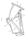
- the device 10 has a guide, with which the drawer 16 from one in Figure 1 shown, inserted into the housing 12 basic position in a in Figures 2 and 3 shown use position is displaceable, in which the drawer 16 from the Housing 12 protrudes.
- the guide of the drawer 16 has a plate-shaped slide 18 on a bottom 20 of the housing 12 ( Figure 4).
- the slider 18 engages laterally in grooves 22 of the housing bottom 20 and is thereby displaceable on the housing bottom 20 led.
- a pin connection 24 Figure 2
- the drawer is the 16th pivotally mounted on a front edge 26 of the slider 18.
- the housing 12 slide tracks 30, in the slide pins 32nd engage, which protrude laterally from the drawer 16 at a rear side.
- the scenery tour with the slide tracks 30 and the slide pin 32 causes a front End of drawer 16 when pulling down to the use position down pivots so that the drawer 16 in the position of use inclined downwards Situation in which their interior is easily accessible.
- the displacement of the drawer 16 in the use position is effected by an opening spring element.
- the opening spring element is in the illustrated embodiment a leg spring 23 which is attached to the bottom 20 of the housing 12 and the Drawer 16 presses on the slider 18 in the position of use. Closing the Drawer, so moving into the basic position in the housing 12, takes place against the spring force of the leg spring 23.
- the sliding movement of the drawer 16 is attenuated by a known rotational damping element 34, the side is attached to the drawer 16 in the rear area.
- a gear 36 of the rotary damping element 34 meshes with a not shown in the drawing Rack on an inner side of a side wall 28 of the housing 12th
- the drawer 16 with a known push-push locking device (Heart curve mechanism) 29 locked at the bottom of the Slider 18 is arranged.
- the push-push locking device 29 is through Pressure against a front panel 38 of the drawer 16 unlocked, so by pressing the drawer 16 a short distance over the basic position away in the housing 12th into it.
- After unlocking the push-push locking device 29 opens the Leg spring 23 the drawer 16, d. H. the leg spring 23 shifts the drawer 16 in the position of use.
- the device 10 has a safety locking device, which is the drawer 16 locked in an accident of the motor vehicle in the basic position.
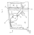
- the safety locking device is shown in Figures 4 and 5.
- the drawer 16 is the clear representation of the safety locking device because of these two Figures not drawn.
- the safety locking device has a bar 40 in the form of a stretched, at one end of cranked lever.
- the latch 40 is obliquely at an angle from about 45 ° to the sliding direction of the drawer 16 and the side of the slider 18 on the Caseback 20 is arranged.
- the bolt 40 At its the slider 18 far end, the bolt 40 a not visible in the drawing pivot on the pin in a hole engages the housing bottom 20.
- the latch 40 is thereby about a pivot axis 42 pivotally mounted on the housing bottom 20.
- the latch 40 has a weight 44, which is molded with a bar 40 forming plastic. In the range of weight 44 is a center of mass of the bolt 40. On one of the pivot axis 42nd facing away from the weight 44, the latch 40 extends to one side of the Slide 18.
- the pivot axis 42 distant end of the bolt 40 forms an engagement point 46.
- the distance of the engagement point 46 of the pivot axis 42 is essential greater than the distance of the weight 44 from the pivot axis 42.
- the swivel angle of the bolt 40 is limited, it can be between a base stop 48 and a End stop 50, both of which are arranged on the housing bottom 20, swing back and forth.
- the voltage applied to the end stop 50 position of the bolt 40 is shown in Figure 5 with Dashed lines indicated.
- the latch 40 In the voltage applied to the base stop 48 position is located the latch 40 with its engagement point 46 outside the path of the slider 18 of the Drawer 16. If the latch 40 on the end stop 50, its engagement point 46 projects into the path of a slide 18 upwardly projecting nose 54, so that the slider 18 only a short distance over the basic position away in the housing 12 slidably is. This displacement is so short that it unlocks the push-push locking device 29 of the drawer 16 prevented.
- the function of the safety locking device of the device according to the invention 10 is the following: In the case of, for example, a rear-end collision or impact on an obstacle is a high acceleration (deceleration) on the not shown Cars. This acceleration of the car strongly retarding causes the latch 40 and the drawer 16 with its slider 18 relative to the car and thus move to the housing 12 of the device 10. The movement of the bolt 40 and the drawer 16 with the slider 18 extends in the direction of a rear wall 54 of the Housing 12, in Figure 5 so up. The bolt 40 thereby passes into that in FIG. 5 indicated by dashed lines position in which it rests on the end stop 50.
- the intervention site 46 of the bolt 40 protrudes into the path of the nose 54 of the slider 18 and blocked thereby moving the slider 18 into the housing 12 before this movement the push-push locking device 29 of the drawer 16 unlocked.
- the Drawer 16 remains characterized in its inserted into the housing 12 basic position locked so that inserted into the drawer 16 items can not fall out.
- the weight 44 of the bolt 40 moves in an accident about the same Speed as the drawer 16 with its slider 18.
- the point of intervention 46 of Bolt 40 moves at a much higher speed than the weight 44 because their distance from the pivot axis 42 is greater.
- the spring force of the leg spring 52 of the bolt 40 is selected so that it locks the bolt 40 in the case of normal driving and also when braking sharply Accelerations against the base stop 48 holds pressed so that the drawer 16 can be opened at any time during normal driving and the latch 40 no Rattling noises generated. Furthermore, the leg spring 52 is so weakly formed that due to the accelerations occurring in an accident that significantly are greater than the accelerations occurring during normal driving, the engagement point 46 moves faster relative to the housing 12 than the drawer 16 with her slide 18.
Landscapes
- Engineering & Computer Science (AREA)
- Mechanical Engineering (AREA)
- Vehicle Step Arrangements And Article Storage (AREA)
- Lock And Its Accessories (AREA)
Description
- Figur 1
- eine erfindungsgemäße Vorrichtung in einer Grundstellung in Seitenansicht;
- Figur 2
- die Vorrichtung aus Figur 1 in einer Gebrauchsstellung;
- Figur 3
- die Vorrichtung aus Figur 1 in der Gebrauchsstellung in perspektivischer Darstellung;
- Figur 4
- ein Gehäuse der Vorrichtung aus Figur 1 in perspektivischer Darstellung; und
- Figur 5
- eine Draufsicht auf einen Boden des Gehäuses der Vorrichtung aus Figur 1.
Claims (3)
- Vorrichtung zum Einbau in einen Kraftwagen, mit einem Ausziehteil (16), das mit einer Führung aus einer Grundstellung in eine Gebrauchsstellung und umgekehrt bewegbar geführt ist, wobei die Vorrichtung (10) eine Sicherheitsverriegelungseinrichtung mit einem beweglichen Riegel (40) aufweist, der durch eine Beschleunigung in einen das Ausziehteil (16) in der Grundstellung verriegelnden Eingriff mit dem Ausziehteil (16) bringbar ist, wobei der Riegel mit einem Schwenkgelenk um einen begrenzten Schwenkwinkel schwenkbar ist und wobei eine Eingriffstelle (46) des Riegels (40), die einen Abstand von einer Schwenkachse (42) des Riegels (40) aufweist, in einen das Ausziehteil (16) in der Grundstellung verriegelnden Eingriff mit dem Ausziehteil (16) bringbar ist, und wobei ein Massenmittelpunkt des Riegels (40) sich zwischen der Schwenkachse (42) und der Eingriffstelle (46) des Riegels (40) befindet, dadurch gekennzeichnet, dass der Riegel (40) eine vergrößerte Masse (44) im Bereich seines Massenmittelpunktes aufweist.
- Vorrichtung nach Anspruch 1, dadurch gekennzeichnet, dass das Ausziehteil eine Schublade (16) ist.
- Vorrichtung nach Anspruch 1, dadurch gekennzeichnet, dass das Ausziehteil (16) mit einer entriegelbaren Push-Push-Verriegelungseinrichtung in der Grundstellung verriegelt ist und von einem Öffnungsfederelement in die Gebrauchsstellung bewegt wird.
Applications Claiming Priority (2)
| Application Number | Priority Date | Filing Date | Title |
|---|---|---|---|
| DE19835364 | 1998-08-05 | ||
| DE19835364A DE19835364C2 (de) | 1998-08-05 | 1998-08-05 | Vorrichtung zum Einbau in einem Kraftwagen mit einem Ausziehteil |
Publications (2)
| Publication Number | Publication Date |
|---|---|
| EP0978418A1 EP0978418A1 (de) | 2000-02-09 |
| EP0978418B1 true EP0978418B1 (de) | 2003-06-04 |
Family
ID=7876545
Family Applications (1)
| Application Number | Title | Priority Date | Filing Date |
|---|---|---|---|
| EP99112921A Expired - Lifetime EP0978418B1 (de) | 1998-08-05 | 1999-07-05 | Vorrichtung zum Einbau in einen Kraftwagen mit einem Ausziehteil |
Country Status (6)
| Country | Link |
|---|---|
| US (1) | US6213533B1 (de) |
| EP (1) | EP0978418B1 (de) |
| JP (1) | JP3451036B2 (de) |
| KR (1) | KR20000016912A (de) |
| DE (2) | DE19835364C2 (de) |
| ES (1) | ES2198818T3 (de) |
Families Citing this family (36)
| Publication number | Priority date | Publication date | Assignee | Title |
|---|---|---|---|---|
| US6746067B2 (en) * | 2001-09-04 | 2004-06-08 | Lear Corporation | Control panel for a vehicle |
| DE20116159U1 (de) * | 2001-10-02 | 2002-02-21 | TRW Automotive Electronics & Components GmbH & Co.KG, 67677 Enkenbach-Alsenborn | Verriegelungsvorrichtung |
| US20050028831A1 (en) * | 2002-01-13 | 2005-02-10 | Sloan Mark C. | Exterior vehicle ashtray system |
| US6682117B2 (en) * | 2002-01-13 | 2004-01-27 | Mark C. Sloan | Exterior vehicle ashtray system |
| JP2003276515A (ja) * | 2002-03-22 | 2003-10-02 | Nifco Inc | スライド及び回動運動のガイド機構、該ガイド機構を用いた蓋体の開閉機構、及び該開閉機構を用いた車載用内装品 |
| JP2003276516A (ja) * | 2002-03-25 | 2003-10-02 | Nifco Inc | ガイド機構、該ガイド機構を用いた蓋体の開閉機構、及び該開閉機構を用いた車載用内装品 |
| US6921141B1 (en) * | 2002-06-13 | 2005-07-26 | Crp Enterprises | Water resistant instrument enclosure |
| KR100464010B1 (ko) * | 2002-11-19 | 2004-12-31 | 엘지전자 주식회사 | 자동차용 정보재생 장치의 잠금장치 |
| DE10340673A1 (de) * | 2003-09-04 | 2005-03-31 | Fischer Automotive Systems Gmbh | Sicherheitsverriegelungsvorrichtung für ein Behältnis in einem Fahrzeug |
| US6899364B2 (en) * | 2003-10-17 | 2005-05-31 | Hyundai Mobis Co., Ltd. | Stopper structure in a glove box |
| US7165798B2 (en) * | 2004-02-06 | 2007-01-23 | Paccar Inc | Instrument mounting assembly |
| US7097220B2 (en) * | 2004-09-23 | 2006-08-29 | Lear Corporation | G-force push-push latch |
| US7192072B2 (en) * | 2005-02-18 | 2007-03-20 | Lear Corporation | Movable panel assembly |
| KR100645186B1 (ko) * | 2005-07-07 | 2006-11-10 | 현대모비스 주식회사 | 센터 어퍼 트레이 |
| JP4687470B2 (ja) | 2006-01-19 | 2011-05-25 | スズキ株式会社 | 車両室内の収納構造 |
| DE102006046562A1 (de) * | 2006-09-30 | 2008-04-03 | Bayerische Motoren Werke Ag | Verdeckt angeordnetes Staufach in einem Kraftfahrzeug-Innenraum |
| US8317236B2 (en) * | 2008-04-16 | 2012-11-27 | Electrolux Home Products, Inc. | Appliance drawer and latch mechanism therefor |
| DE102008020433A1 (de) | 2008-04-24 | 2009-10-29 | Fischer Automotive Systems Gmbh & Co. Kg | Verriegelungseinrichtung für Kraftfahrzeuginnenraumkomponenten |
| KR100893442B1 (ko) * | 2008-05-07 | 2009-04-17 | 기아자동차주식회사 | 오픈 방지 구조를 갖는 차량용 트레이 |
| KR100921299B1 (ko) * | 2008-06-30 | 2009-10-09 | 현대자동차주식회사 | 트레이 열림 방지장치 |
| US7850219B2 (en) * | 2008-10-08 | 2010-12-14 | Gm Global Technology Operations, Inc. | Viscous rotary damper for vehicle end gate assembly |
| DE102009060119B4 (de) * | 2009-12-15 | 2018-03-01 | Illinois Tool Works Inc. | Betätigungsvorrichtung |
| DE102010005420B4 (de) * | 2010-01-22 | 2022-12-29 | Dr. Ing. H.C. F. Porsche Aktiengesellschaft | Verriegelungsvorrichtung für einen Deckel eines Behältnisses in einem Kraftfahrzeug |
| DE202010006291U1 (de) * | 2010-04-30 | 2011-09-23 | Minda Ktsn Plastic Solutions Gmbh & Co.Kg | Verriegelungseinrichtung |
| DE102010050800A1 (de) * | 2010-11-09 | 2012-05-10 | Audi Ag | Verriegelungseinrichtung mit einer Push-Push-Mechanik für einen zwischen einer Schließ- und Offenstellung betätigbaren Behälter oder Deckel, insbesondere von Kraftfahrzeugen |
| DE102011111269A1 (de) | 2011-08-22 | 2013-02-28 | Faurecia Innenraum Systeme Gmbh | Ablagefach-Vorrichtung |
| KR101417535B1 (ko) | 2012-12-31 | 2014-07-08 | 현대자동차주식회사 | 자동차의 멀티 박스 |
| AT514058B1 (de) * | 2013-04-12 | 2014-10-15 | Blum Gmbh Julius | Antriebsvorrichtung für ein bewegbares Möbelteil |
| DE102014103792A1 (de) | 2014-03-20 | 2015-09-24 | Dr. Ing. H.C. F. Porsche Aktiengesellschaft | Verriegelung für eine schwenkbare Abdeckung in einem Fahrzeug |
| FR3047211B1 (fr) * | 2016-01-28 | 2018-03-02 | Faurecia Interieur Industrie | Dispositif ouvrant comprenant un dispositif de blocage de securite |
| US10625683B2 (en) | 2018-03-29 | 2020-04-21 | Ford Global Technologies, Llc | Push hanger hook |
| KR102603037B1 (ko) * | 2018-10-30 | 2023-12-04 | 현대자동차주식회사 | 차량의 수납 장치 |
| CN112092735B (zh) * | 2020-07-31 | 2022-02-11 | 东风延锋汽车饰件系统有限公司 | 用于汽车驾驶室内的带隐藏扣手的抽屉式储物盒 |
| CN115956155A (zh) | 2020-08-19 | 2023-04-11 | 韦伯两合公司塑料技术与成形 | 用于尤其是机动车的、可相对于壳体部件在关闭位态和打开位态之间操纵的容器或盖的锁定装置 |
| KR20240144209A (ko) * | 2022-01-24 | 2024-10-02 | 테슬라, 인크. | 파워-슬라이드 차량 격실들 |
| DE102023104395B4 (de) | 2023-02-23 | 2024-09-05 | Weber Gmbh & Co. Kg Kunststofftechnik Und Formenbau | Verriegelungsvorrichtung für einen gegenüber einem Gehäuseteil, insbesondere von Kraftfahrzeugen, zwischen einer Offen- und Schließstellung betätigbaren Deckel sowie Verfahren zum Ver- und Entriegeln eines einen Gehäuseteil verschließenden Deckels |
Family Cites Families (31)
| Publication number | Priority date | Publication date | Assignee | Title |
|---|---|---|---|---|
| US2798632A (en) * | 1954-07-12 | 1957-07-09 | Gen Motors Corp | Ash tray assembly |
| US4006951A (en) * | 1975-06-12 | 1977-02-08 | Adams Rite Products, Inc. | Locking mechanism for a slide drawer |
| JPS54109241U (de) * | 1978-01-13 | 1979-08-01 | ||
| US4422522A (en) * | 1982-01-21 | 1983-12-27 | Lectron Products, Inc. | Inertial lock for vehicle door latch |
| US4494806A (en) * | 1983-05-13 | 1985-01-22 | Leslie Metal Arts Company | Spring loaded drawer assembly with mechanical damping |
| JPS606650U (ja) * | 1983-06-22 | 1985-01-18 | 本田技研工業株式会社 | 車両のインストルメントパネルに設けられる小物収納ボツクス |
| DE3432739A1 (de) * | 1984-09-06 | 1986-03-13 | Adam Opel AG, 6090 Rüsselsheim | Kraftfahrzeug |
| JPH049830Y2 (de) * | 1985-10-15 | 1992-03-11 | ||
| JP2707126B2 (ja) * | 1988-12-26 | 1998-01-28 | 株式会社ニフコ | 自動車用灰皿装置 |
| JPH077225Y2 (ja) * | 1989-10-18 | 1995-02-22 | 株式会社ニフコ | 車載移動体の閉位置係止装置 |
| US4988134A (en) * | 1990-05-03 | 1991-01-29 | Hoover Universal, Inc. | Inertia latching mechanism with floating striker bar |
| EP0525811A1 (de) * | 1991-08-02 | 1993-02-03 | UNITED TECHNOLOGIES AUTOMOTIVE, Inc. | Fahrzeugkonsole mit Trägheitstürschloss |
| DE4130847C2 (de) * | 1991-09-17 | 1995-04-13 | Daimler Benz Ag | Verschlußkappe zum Verschließen eines Ablagefaches im Innenraum eines Kraftfahrzeuges |
| US5263346A (en) * | 1991-10-15 | 1993-11-23 | Kato Hatsujo Kaisha, Ltd. | Locking device for lid |
| DE4141239A1 (de) * | 1991-12-14 | 1993-06-17 | Audi Ag | Beweglicher handschuhkasten |
| JPH0575004U (ja) * | 1992-03-16 | 1993-10-12 | 加藤発条株式会社 | 安全機能付き自動車用収納装置 |
| EP0561113B1 (de) * | 1992-03-16 | 1997-05-21 | Kato Hatsujo Kaisha Ltd. | Sicherheitsverriegelung für ein Fahrzeugablagefach |
| JPH0575003U (ja) * | 1992-03-16 | 1993-10-12 | 加藤発条株式会社 | 安全機能付き自動車用収納装置 |
| US5255983A (en) * | 1992-07-28 | 1993-10-26 | Accuride International, Inc. | Shock absorbing disconnect latch for ball bearing slides |
| JP3156880B2 (ja) * | 1992-09-28 | 2001-04-16 | 本田技研工業株式会社 | 車両のグローブボックス構造 |
| US5308130A (en) * | 1992-12-18 | 1994-05-03 | General Motors Corporation | Vehicle door latch |
| DE69400926T2 (de) * | 1993-02-12 | 1997-06-12 | Kato Hatsujo Kaisha Ltd | Bewahrungsvorrichtung mit einer Sicherheitsfunktion |
| US5522638A (en) * | 1993-03-25 | 1996-06-04 | United Technologies Automotive, Inc. | Multifunctional garage door opener storage compartment |
| US5507423A (en) * | 1995-02-28 | 1996-04-16 | Prince Corporation | Push-push vehicle clothes hook assembly |
| DE19534436A1 (de) * | 1995-09-16 | 1997-03-20 | Daimler Benz Ag | Cockpitbereich für eine Beifahrerseite eines Kraftfahrzeugs |
| DE29518173U1 (de) * | 1995-11-16 | 1996-01-11 | Itw-Ateco Gmbh, 22844 Norderstedt | Vorrichtung zur Dämpfung der Bewegung eines beweglich gelagerten Bauteils, insbesondere einer Klappe in einem Automobil o.dgl. |
| JP3451156B2 (ja) * | 1995-12-19 | 2003-09-29 | 本田技研工業株式会社 | 自動車の天井用小物入れ |
| US5669642A (en) * | 1996-06-05 | 1997-09-23 | Hyundai Motor Company | Outside door handle automatic locking device for automobiles |
| KR19980028248A (ko) * | 1996-10-21 | 1998-07-15 | 박병재 | 자동차의 접이식 컵 홀더 |
| DE19756908A1 (de) * | 1997-12-19 | 1999-06-24 | Bayerische Motoren Werke Ag | Vorrichtung zum Halten eines Gegenstandes in einem Fahrzeug |
| US6062623A (en) * | 1998-05-18 | 2000-05-16 | Prince Corporation | Latch for vehicle overhead storage bin |
-
1998
- 1998-08-05 DE DE19835364A patent/DE19835364C2/de not_active Expired - Fee Related
-
1999
- 1999-07-05 EP EP99112921A patent/EP0978418B1/de not_active Expired - Lifetime
- 1999-07-05 DE DE59905801T patent/DE59905801D1/de not_active Expired - Fee Related
- 1999-07-05 ES ES99112921T patent/ES2198818T3/es not_active Expired - Lifetime
- 1999-07-08 KR KR1019990027409A patent/KR20000016912A/ko not_active Ceased
- 1999-08-03 US US09/368,026 patent/US6213533B1/en not_active Expired - Fee Related
- 1999-08-04 JP JP22159999A patent/JP3451036B2/ja not_active Expired - Fee Related
Also Published As
| Publication number | Publication date |
|---|---|
| DE19835364C2 (de) | 2000-06-08 |
| EP0978418A1 (de) | 2000-02-09 |
| DE59905801D1 (de) | 2003-07-10 |
| KR20000016912A (ko) | 2000-03-25 |
| ES2198818T3 (es) | 2004-02-01 |
| JP3451036B2 (ja) | 2003-09-29 |
| US6213533B1 (en) | 2001-04-10 |
| JP2000052879A (ja) | 2000-02-22 |
| DE19835364A1 (de) | 2000-02-17 |
Similar Documents
| Publication | Publication Date | Title |
|---|---|---|
| EP0978418B1 (de) | Vorrichtung zum Einbau in einen Kraftwagen mit einem Ausziehteil | |
| DE4130847C2 (de) | Verschlußkappe zum Verschließen eines Ablagefaches im Innenraum eines Kraftfahrzeuges | |
| DE102011118576B4 (de) | Betätigungsvorrichtung | |
| AT508139B1 (de) | Möbelantrieb mit touch-latch-vorrichtung | |
| EP3484327B1 (de) | Antriebsvorrichtung für ein bewegbares möbelteil und verfahren zum öffnen und schliessen eines bewegbaren möbelteils | |
| EP3449077B1 (de) | Ausstossvorrichtung für ein bewegbares möbelteil und möbel | |
| EP1253271A2 (de) | Push-Push-Verriegelungsmechanik | |
| DE102004030563A1 (de) | System zum Verriegeln eines ersten Elementes bezüglich eines zweiten Elementes und mit solch einem Verriegelungssystem ausgestatteter Sitz | |
| DE10248358B4 (de) | Becherhalter | |
| DE102010050800A1 (de) | Verriegelungseinrichtung mit einer Push-Push-Mechanik für einen zwischen einer Schließ- und Offenstellung betätigbaren Behälter oder Deckel, insbesondere von Kraftfahrzeugen | |
| DE102007034556A1 (de) | Verriegelungseinrichtung für die Frontklappe eines Kraftfahrzeuges | |
| EP0760309B1 (de) | Vorrichtung zum Verriegeln und Entriegeln eines Becherbehälters | |
| DE102007013081B4 (de) | Armlehne, insbesondere für Kraftfahrzeuge | |
| DE102015114788A1 (de) | Behältnis mit einer Sicherheitsverriegelungsmechanik für ein Fahrzeug | |
| EP1660743B1 (de) | Sicherheitsverriegelungsvorrichtung für ein behältnis in einem fahrzeug | |
| DE10027020A1 (de) | Mittelkonsole für Fahrzeuge | |
| EP0841213B1 (de) | Fahrzeugascher | |
| DE10009291B4 (de) | Armlehne mit Staufach und verriegelbarem Deckel | |
| DE102011090019B4 (de) | Entriegelungssperrvorrichtung, Aufbewahrungsfach mit Entriegelungssperrvorrichtung | |
| EP0849113B1 (de) | Einbauaschenbecher in ein Kraftfahrzeug | |
| EP1509663B1 (de) | Sicherheitsverriegelungsvorrichtung f r ein beh ltnis i n einem fahrzeug | |
| EP3990727B1 (de) | Verriegelungsvorrichtung für einen zwischen einer schliess- und offenstellung bestätigbaren behälter oder deckel, insbesondere von kraftfahrzeugen | |
| DE102009052633B4 (de) | Verschlussvorrichtung und Verwendung der Verschlussvorrichtung | |
| DE19532276C2 (de) | Laderaumabdeckung für einen Kombi-Personenkraftwagen | |
| DE102023104395B4 (de) | Verriegelungsvorrichtung für einen gegenüber einem Gehäuseteil, insbesondere von Kraftfahrzeugen, zwischen einer Offen- und Schließstellung betätigbaren Deckel sowie Verfahren zum Ver- und Entriegeln eines einen Gehäuseteil verschließenden Deckels |
Legal Events
| Date | Code | Title | Description |
|---|---|---|---|
| PUAI | Public reference made under article 153(3) epc to a published international application that has entered the european phase |
Free format text: ORIGINAL CODE: 0009012 |
|
| AK | Designated contracting states |
Kind code of ref document: A1 Designated state(s): DE ES FR GB IT SE |
|
| AX | Request for extension of the european patent |
Free format text: AL;LT;LV;MK;RO;SI |
|
| 17P | Request for examination filed |
Effective date: 20000620 |
|
| AKX | Designation fees paid |
Free format text: DE ES FR GB IT SE |
|
| 17Q | First examination report despatched |
Effective date: 20020515 |
|
| GRAH | Despatch of communication of intention to grant a patent |
Free format text: ORIGINAL CODE: EPIDOS IGRA |
|
| GRAH | Despatch of communication of intention to grant a patent |
Free format text: ORIGINAL CODE: EPIDOS IGRA |
|
| GRAA | (expected) grant |
Free format text: ORIGINAL CODE: 0009210 |
|
| PGFP | Annual fee paid to national office [announced via postgrant information from national office to epo] |
Ref country code: DE Payment date: 20030521 Year of fee payment: 5 |
|
| AK | Designated contracting states |
Designated state(s): DE ES FR GB IT SE |
|
| REG | Reference to a national code |
Ref country code: GB Ref legal event code: FG4D Free format text: NOT ENGLISH |
|
| REG | Reference to a national code |
Ref country code: SE Ref legal event code: TRGR |
|
| REF | Corresponds to: |
Ref document number: 59905801 Country of ref document: DE Date of ref document: 20030710 Kind code of ref document: P |
|
| ET | Fr: translation filed | ||
| GBT | Gb: translation of ep patent filed (gb section 77(6)(a)/1977) |
Effective date: 20031018 |
|
| REG | Reference to a national code |
Ref country code: ES Ref legal event code: FG2A Ref document number: 2198818 Country of ref document: ES Kind code of ref document: T3 |
|
| PLBE | No opposition filed within time limit |
Free format text: ORIGINAL CODE: 0009261 |
|
| STAA | Information on the status of an ep patent application or granted ep patent |
Free format text: STATUS: NO OPPOSITION FILED WITHIN TIME LIMIT |
|
| PGFP | Annual fee paid to national office [announced via postgrant information from national office to epo] |
Ref country code: FR Payment date: 20040506 Year of fee payment: 6 |
|
| 26N | No opposition filed |
Effective date: 20040305 |
|
| PGFP | Annual fee paid to national office [announced via postgrant information from national office to epo] |
Ref country code: ES Payment date: 20040607 Year of fee payment: 6 |
|
| PGFP | Annual fee paid to national office [announced via postgrant information from national office to epo] |
Ref country code: GB Payment date: 20040630 Year of fee payment: 6 |
|
| PGFP | Annual fee paid to national office [announced via postgrant information from national office to epo] |
Ref country code: SE Payment date: 20040714 Year of fee payment: 6 |
|
| PG25 | Lapsed in a contracting state [announced via postgrant information from national office to epo] |
Ref country code: DE Free format text: LAPSE BECAUSE OF NON-PAYMENT OF DUE FEES Effective date: 20050201 |
|
| PG25 | Lapsed in a contracting state [announced via postgrant information from national office to epo] |
Ref country code: IT Free format text: LAPSE BECAUSE OF NON-PAYMENT OF DUE FEES Effective date: 20050705 Ref country code: GB Free format text: LAPSE BECAUSE OF NON-PAYMENT OF DUE FEES Effective date: 20050705 |
|
| PG25 | Lapsed in a contracting state [announced via postgrant information from national office to epo] |
Ref country code: SE Free format text: LAPSE BECAUSE OF NON-PAYMENT OF DUE FEES Effective date: 20050706 Ref country code: ES Free format text: LAPSE BECAUSE OF NON-PAYMENT OF DUE FEES Effective date: 20050706 |
|
| EUG | Se: european patent has lapsed | ||
| GBPC | Gb: european patent ceased through non-payment of renewal fee |
Effective date: 20050705 |
|
| PG25 | Lapsed in a contracting state [announced via postgrant information from national office to epo] |
Ref country code: FR Free format text: LAPSE BECAUSE OF NON-PAYMENT OF DUE FEES Effective date: 20060331 |
|
| REG | Reference to a national code |
Ref country code: FR Ref legal event code: ST Effective date: 20060331 |
|
| REG | Reference to a national code |
Ref country code: ES Ref legal event code: FD2A Effective date: 20050706 |