EP0971091B1 - Gelenkanordnung zur Betätigung einer Klappe oder dergleichen - Google Patents
Gelenkanordnung zur Betätigung einer Klappe oder dergleichen Download PDFInfo
- Publication number
- EP0971091B1 EP0971091B1 EP99113108A EP99113108A EP0971091B1 EP 0971091 B1 EP0971091 B1 EP 0971091B1 EP 99113108 A EP99113108 A EP 99113108A EP 99113108 A EP99113108 A EP 99113108A EP 0971091 B1 EP0971091 B1 EP 0971091B1
- Authority
- EP
- European Patent Office
- Prior art keywords
- drive element
- linear drive
- flap
- axis
- lever
- Prior art date
- Legal status (The legal status is an assumption and is not a legal conclusion. Google has not performed a legal analysis and makes no representation as to the accuracy of the status listed.)
- Expired - Lifetime
Links
Images

Classifications
-
- A—HUMAN NECESSITIES
- A62—LIFE-SAVING; FIRE-FIGHTING
- A62C—FIRE-FIGHTING
- A62C2/00—Fire prevention or containment
- A62C2/06—Physical fire-barriers
- A62C2/24—Operating or controlling mechanisms
-
- E—FIXED CONSTRUCTIONS
- E05—LOCKS; KEYS; WINDOW OR DOOR FITTINGS; SAFES
- E05F—DEVICES FOR MOVING WINGS INTO OPEN OR CLOSED POSITION; CHECKS FOR WINGS; WING FITTINGS NOT OTHERWISE PROVIDED FOR, CONCERNED WITH THE FUNCTIONING OF THE WING
- E05F15/00—Power-operated mechanisms for wings
- E05F15/50—Power-operated mechanisms for wings using fluid-pressure actuators
- E05F15/53—Power-operated mechanisms for wings using fluid-pressure actuators for swinging wings
-
- F—MECHANICAL ENGINEERING; LIGHTING; HEATING; WEAPONS; BLASTING
- F24—HEATING; RANGES; VENTILATING
- F24F—AIR-CONDITIONING; AIR-HUMIDIFICATION; VENTILATION; USE OF AIR CURRENTS FOR SCREENING
- F24F13/00—Details common to, or for air-conditioning, air-humidification, ventilation or use of air currents for screening
- F24F13/08—Air-flow control members, e.g. louvres, grilles, flaps or guide plates
- F24F13/10—Air-flow control members, e.g. louvres, grilles, flaps or guide plates movable, e.g. dampers
- F24F13/14—Air-flow control members, e.g. louvres, grilles, flaps or guide plates movable, e.g. dampers built up of tilting members, e.g. louvre
-
- E—FIXED CONSTRUCTIONS
- E05—LOCKS; KEYS; WINDOW OR DOOR FITTINGS; SAFES
- E05Y—INDEXING SCHEME RELATING TO HINGES OR OTHER SUSPENSION DEVICES FOR DOORS, WINDOWS OR WINGS AND DEVICES FOR MOVING WINGS INTO OPEN OR CLOSED POSITION, CHECKS FOR WINGS AND WING FITTINGS NOT OTHERWISE PROVIDED FOR, CONCERNED WITH THE FUNCTIONING OF THE WING
- E05Y2900/00—Application of doors, windows, wings or fittings thereof
- E05Y2900/10—Application of doors, windows, wings or fittings thereof for buildings or parts thereof
- E05Y2900/13—Application of doors, windows, wings or fittings thereof for buildings or parts thereof characterised by the type of wing
- E05Y2900/148—Windows
- E05Y2900/152—Roof windows
- E05Y2900/154—Skylights
-
- F—MECHANICAL ENGINEERING; LIGHTING; HEATING; WEAPONS; BLASTING
- F24—HEATING; RANGES; VENTILATING
- F24F—AIR-CONDITIONING; AIR-HUMIDIFICATION; VENTILATION; USE OF AIR CURRENTS FOR SCREENING
- F24F11/00—Control or safety arrangements
- F24F11/30—Control or safety arrangements for purposes related to the operation of the system, e.g. for safety or monitoring
- F24F11/32—Responding to malfunctions or emergencies
- F24F11/33—Responding to malfunctions or emergencies to fire, excessive heat or smoke
- F24F11/34—Responding to malfunctions or emergencies to fire, excessive heat or smoke by opening air passages
Definitions
- the invention relates to a hinge assembly for actuation a flap or the like according to the preamble of the claim 1.
- the Joint arrangement can be single or double flaps made of sheet metal be actuated or slats of a lamellar fan.
- a rotatable or tiltable Element such as B. actuates a flap or a blade.
- the hinge assembly is intended to meet the requirement for SHE system, i. Smoke and heat exhaust systems meet, where a smoke vent in alarm position a large opening angle of should reach about 165 °.
- a known joint arrangement of the type mentioned is completely independent in and out of such an alert operable, with the opening and closing of a Flap over a whole large swivel range to about 165 ° may be, for which only a drive element is needed.
- a known hinge assembly is an end of a linear drive element at one of a stationary first Rotary axis of a flap or dome remote location of the flap pivotally mounted on a truss part of the flap.
- the linear drive element is a first Swivel axis pivotally mounted on a support lever, the in turn around a fixed second pivot axis nearby the axis of rotation of the flap is pivotable. This is the first Swivel axis approximately in the middle of the longitudinal extent of the support lever.
- An additional bellcrank is with a first end at an end remote from the second pivot axis of the Support lever arranged pivotally.
- a second end of the reversing lever engages pivotally on the truss part of the flap at a distance to its axis of rotation and to the mounting location of the first end of the drive element (EP 0 443 050 B1).
- These Joint arrangement is distinguished from other joint arrangements by a relatively space-saving position of the linear Drive elements, in particular a lifting cylinder, off.
- a less space-saving variant of the joint arrangement with only one linear drive element is at the first Pivot axis of the additional lever with a first end pivotally arranged, the second end of the truss part the flap at a distance to its axis of rotation and to the mounting location the first end of the drive element attacks.
- the invention is therefore based on the object, a joint assembly of the type mentioned above in such a way that this on the flap, lamella or the like, at the linear drive element attacks, no additional lateral forces initiates, so that the traverse or a truss bottom is not required.
- the hinge assembly with these features can be designed be that they are also used to operate smoke flaps in SHE systems have a large opening angle with completely independent Opening and closing allows, without being on the smoke damper flap to apply additional lateral forces, the otherwise intercept by a truss part. It will only Forces in the flap or the actuatable element the axis of rotation or hinge as well as on the swivel executed Location of the linear drive element on the Flap, the latter location substantially parallel to the axis of rotation is opposite, initiated. Reaction forces of the linear Drive elements are via the lever and the support lever only in a fixed pivot point of the reversing lever or a stationary second pivot axis of the support lever initiated.
- the hinge assembly according to the invention may be in their dimensions adapted flexibly to given operational requirements as long as the characteristics of the characterizing part of the Claim 1 are satisfied.
- the second end of the reversing lever at a fixed pivot point and the third pivot axis about which the bellcrank the linear drive element is pivotable must be observed be that the first pivot axis of the linear drive element on the support lever and the third pivot axis to which of the lever on the linear drive element is pivotable when operating the linear drive element describe circular trajectories that intersect and cause a resultant rotation of the linear drive element.
- the drive element can be linear move, in the case of a flap, to which the linear drive element, in particular a piston rod a compressed air cylinder in the closed state from below engages, during the rotation of the linear drive element this simultaneously moved up.
- a simple basic form of the joint arrangement is apparent according to claim 3, characterized in that the second end of the reversing lever at the fixed pivot closer to the stationary first axis of rotation of the flap as the stationary second pivot axis the support lever and preferably under the fixed second pivot axis of the support lever is mounted.
- This embodiment is especially recommended for a fixed Console in a curb.
- this console is fixed according to claim 4 Fulcrum of the second end of the bell crank on the fixed console, which is near the axis of rotation of the flap from this in its closed position preferably in Substantially perpendicular to this protrudes, in essence arranged below the axis of rotation of the flap.
- the stationary second pivot axis of the support lever on the console is in substantially below the fixed pivot point of the second End of the reversing lever attached to the console.
- the third pivot axis about which the linear drive element is pivotable at one end of the support lever.
- Compressed air are supplied, as well as the first Pivot axis of the linear drive element on the support lever.
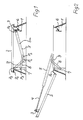
- Fig. 1 denotes a curb, on which a flap by means of a hinge about a stationary first axis of rotation P 0 is pivotable.
- a piston rod 4 of a Doppelhubzylinders 5 At the opposite end to the first axis of rotation P 0 engages the flap 2 via a locking element 3, a piston rod 4 of a Doppelhubzylinders 5 as a linear drive element.
- the pivotable connection of the piston rod to the locking element 3 and the flap 2 is designated P 1 .
- the locking element cooperates with a locking bracket 6 which is fixedly mounted inside the curb, such that upon actuation of the piston rod 4, see Fig. 2, an unlocking takes place.
- a bracket 7 is fixed to the inside of the curb, which protrudes approximately at right angles and perpendicularly downward with respect to the closed flap 2.
- the bracket 7 serves to support a support lever 8 and a reversing lever 9, whose one end with a fixed pivot point P 2 closer to the stationary first axis of rotation of the flap is arranged as a fixed pivot axis P 3 of the support lever 8, wherein the fixed pivot point P 2 and the fixed pivot axis P 3 are arranged here along a vertical line.
- the support lever 8 is arranged with an opposite to the stationary pivot axis P 3 end to the Doppelhubzylinder 5 and that in the central axis 5a of this Doppelhubzylinders 5.
- P 5 forms the first pivot axis of the Doppelhubzylinders 5 on the support lever 8, in the region of one end the double-stroke cylinder is arranged opposite to the pivotable connection point P 1 on the locking element 3 or the flap 2.
- the pivot axis P 4 of the reversing lever 9 is arranged.
- the pivot axis P 4 is referred to as the third pivot axis, because at least one second pivot axis is present at the pivotable connection point P 1 .
- the locking element 3 Upon actuation of the Doppelhubzylinders in the alarm position (see Figure 2), the locking element 3 is unlocked by the piston rod 4 of the locking console 6 and the flap 2 is raised and pivoted, with only forces on the first axis of rotation P 0 on the hinge of the flap and on the pivotable connection point P 1 are introduced into the flap, which is thus little burden.
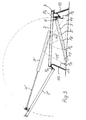
- the kinematics of the arrangement of the flap 2 of the Doppelhubzylinders 5 of the support lever 8 and the reversing lever 9 is formed so that during the pivotal movement of the flap 2, the first pivot axis P 5 of Doppelhubzylinders 5 about the stationary second pivot axis P 3 of the support lever 8 describes a circular path, which intersects with a circular path which describes the point P 4 as the third pivot axis of the Doppelhubzylinders at one end of the reversing lever 9 about its stationary pivot axis P 2 on the console 7. Segments of this circular path are shown in Fig. 3 with dotted lines.
- a first variant which allows the joint arrangement according to the invention, it is assumed from Fig. 3 of a top frame with a bracket 11 which is located on the same side inside of the top frame on which above the first axis of rotation P 0 of the flap 2 is arranged so do not continuously extend from the area of this first axis of rotation P 0 down as the console 7 in Figs. 1 and 2.
- a locking bracket is in the top frame 10 of FIG. 3 on the opposite side inside 12 extends downward.
- FIG. 3 In the first variant of FIG. 3 is a support lever 13, whose central axis is shown with a dash-dot line, pivotally between a first pivot axis P 5 in the central axis of the Doppelhubzylinders 5 as a linear drive element on the one hand and the stationary second pivot axis P 3 , in the Console 11 is mounted below at a vertical distance from the first axis of rotation P 0 , arranged.
- a likewise indicated only by its center line dash-dotted lever 14 is pivotable on the one hand about a third pivot axis P 4 on the Doppelhubzylinder 5 and on the other hand about a fixed pivot point P 2 below in the locking console 12th
- the double-stroke cylinder 5 When the double-stroke cylinder 5 is actuated, it in turn releases with its piston rod 4 a locking element 3 from the locking console 12 and pushes or pivots the flap 2 from the closed horizontal position into the wide-open alarm position of the flap 2 '.
- the kinematics in turn, as in the basic form so that the point P, a circle segment around the point P 2 describes until the bellcrank is in the alarm position 14 '.
- the point P 5 which represents the first pivot axis, describes a circular segment about the fixed second pivot axis P 3 of the support lever 13, which is designated in the alarm position by 13 '. Both circle segments intersect.
- FIG. 4 In the second variant of FIG. 4 is located within a top frame 15 on the opposite to the stationary first axis of rotation of the flap 2 side inside a console 16 which extends from an upper part designed for locking downwards, where in turn a fixed pivot point P. 2 a reversing lever 17 is pivotally mounted. At its opposite end, the reversing lever 17 is in turn arranged on the third pivot axis P 4 of the Doppelhubzylinders as a linear drive element, and indeed at its end, which is opposite to the locking element 3.
- a support lever 18 is further arranged from the end of the Doppelhubzylinders 5 about the first pivot axis of the Doppelhubzylinders P 5 to a support lever 18 which is in the drawn basic position, the closed position of the flap 2, parallel to the Doppelhubzylinder.
- To the first pivot axis P 5 opposite end of the support lever is mounted in a stationary second pivot axis P 3 , which is here perpendicular to the fixed pivot point P 2 of the reversing lever in the console 16.
- This embodiment is thus characterized by the fact that the console 16 opposite the inside of the attachment frame 15 no console or the like may be arranged must, to the reversing lever 17 or the support lever 18 at each store one end stationary. Nevertheless, the principle is Same kinematics with respect to the movement of the flap 2 in achieves the unillustrated wide open alarm position, as shown in Fig. 3.
Landscapes
- Engineering & Computer Science (AREA)
- Emergency Management (AREA)
- Mechanical Engineering (AREA)
- General Engineering & Computer Science (AREA)
- Health & Medical Sciences (AREA)
- Public Health (AREA)
- Combustion & Propulsion (AREA)
- Chemical & Material Sciences (AREA)
- Business, Economics & Management (AREA)
- Transmission Devices (AREA)
- Power-Operated Mechanisms For Wings (AREA)
- Holders For Apparel And Elements Relating To Apparel (AREA)
- Harvester Elements (AREA)
- Mechanically-Actuated Valves (AREA)
- Catching Or Destruction (AREA)
- Air-Flow Control Members (AREA)
Description
- Fig. 1
- in einer Seitenansicht teilweise geschnitten eine Grundform der Gelenkanordnung zur Betätigung einer Klappe mit einem Doppelhubzylinder in einer geschlossenen Grundstellung,
- Fig. 2
- in der gleichen Seitenansicht wie in Fig. 1 die Grundform der Gelenkanordnung in einer weit geöffneten Alarmstellung der Klappe,
- Fig. 3
- ebenfalls in einer Seitenansicht teilweise geschnitten eine erste Variante der Gelenkanordnung in der Grundstellung und in einer weit geöffneten Alarmstellung einer Klappe und
- Fig. 4
- in einer Seitenansicht teilweise geschnitten eine zweite Variante der Gelenkanordnung in der geschlossenen Grundstellung der Klappe.
Claims (9)
- Gelenkanordnung zur Betätigung einer Klappe oder dergleichen, insbesondere Rauchabzugsklappe oder Kuppel, die um eine ortsfeste, erste Drehachse (P0) aus einer geschlossenen Stellung in eine Alarmstellung sowie zurück schwenkbar ist, mit einem linearen Antriebselement (5), dessen eines Ende an einer von der Drehachse entfernten Stelle der Klappe schwenkbar mit der Klappe in Verbindung steht und welches andererseits um eine erste Schwenkachse (P5) schwenkbar an einem Stützhebel (8) angebracht ist, der seinerseits um eine ortsfeste, zweite Schwenkachse (P3) in einem Abstand zu, insbesondere unterhalb der ortsfesten, ersten Drehachse der Klappe schwenkbar ist, wobei ein zusätzlicher Umlenkhebel (9,14,17) mit einem ersten Ende um eine dritte Schwenkachse (P4) schwenkbar an dem Antriebselement (5) angeordnet ist,
dadurch gekennzeichnet, daß ein zweites Ende des Umlenkhebels (9,14,17) an einem festen Drehpunkt (P2) gelagert ist, dergestalt, daß die erste Schwenkachse (P5) des linearen Antriebselements (5) an dem Stützhebel (8,13,18) sowie die dritte Schwenkachse (P4), um welche der Umlenkhebel (9,14,17) an dem linearen Antriebselement (5) schwenkbar ist, bei Betätigung des linearen Antriebselements (5) kreisförmige Bewegungsbahnen beschreiben, die sich kreuzen und eine resultierende Drehung des linearen Antriebselements (5) hervorrufen. - Gelenkanordnung nach Anspruch 1,
dadurch gekennzeichnet, daß die dritte Schwenkachse (P4), um welche das lineare Antriebselement an dem Umlenkhebel (9,14,17) schwenkbar ist, näher zu dem einen Ende des linearen Antriebselements angeordnet ist, welches der Klappe abgewandt ist, als die erste Schwenkachse (P5), um welche der Stützhebel (8,13,18) an dem linearen Antriebselement schwenkbar ist. - Gelenkanordnung nach Anspruch 1 oder 2,
dadurch gekennzeichnet, daß das zweite Ende des Umlenkhebels (9) an den ortsfesten Drehpunkt (P2) näher bei der ortsfesten, ersten Drehachse (P0) der Klappe (2) als die ortsfeste zweite Schwenkachse (P3) des Stützhebels (8) und vorzugsweise unter dieser gelagert ist. - Gelenkanordnung nach Anspruch 3,
dadurch gekennzeichnet, daß der ortsfeste Drehpunkt (P2) des zweiten Endes des Umlenkhebels (9) an einer feststehenden Konsole (7), die in der Nähe der Drehachse (P0) der Klappe (2) von dieser in deren geschlossener Stellung vorzugsweise im wesentlichen rechtwinklig absteht, im wesentlichen unterhalb der Drehachse (P0) der Klappe (2) angeordnet ist und daß die ortsfeste zweite Schwenkachse (P3) des Stützhebels (8) an der Konsole (7) im wesentlichen unterhalb des ortsfesten Drehpunkts (P2) des zweiten Endes des Umlenkhebels (9) an der Konsole (7) angebracht ist. - Gelenkanordnung nach einem der vorangehenden Ansprüche,
dadurch gekennzeichnet, daß die dritte Schwenkachse (P4) des ersten Endes des Umlenkhebels (9,14,17) und die erste Schwenkachse des linearen Antriebselements an dem Stützhebel (8,13,18) in der Mittelachse (5a) des linearen Antriebselements liegen. - Gelenkanordnung nach einem der vorangehenden Ansprüche, gekennzeichnet durch ein lineares Antriebselement, welches geeignet ist, Seitenkräfte aufzunehmen.
- Gelenkanordnung nach einem der vorangehenden Ansprüche,
dadurch gekennzeichnet, daß die Klappe (2) an ihrem zu dem ortsfesten Drehpunkt (P0) entfernten Ende unmittelbar, d.h. ohne Einfügung eines Traversenteils mit dem linearen Antriebselement in schwenkbarer Verbindung steht. - Gelenkanordnung nach einem der vorangehenden Ansprüche,
dadurch gekennzeichnet, daß als lineares Antriebselement ein Doppelhubzylinder (5) vorgesehen ist. - Gelenkanordnung nach Anspruch 3 oder 4,
dadurch gekennzeichnet, daß sich die dritte Schwenkachse (P4), um welche das lineare Antriebselements um den Umlenkhebel (9,14,17) schwenkbar ist, an dem Ende des linearen Antriebselements befindet.
Applications Claiming Priority (2)
| Application Number | Priority Date | Filing Date | Title |
|---|---|---|---|
| DE19830678 | 1998-07-09 | ||
| DE19830678A DE19830678C2 (de) | 1998-07-09 | 1998-07-09 | Gelenkanordnung zur Betätigung einer Klappe oder dergleichen |
Publications (3)
| Publication Number | Publication Date |
|---|---|
| EP0971091A2 EP0971091A2 (de) | 2000-01-12 |
| EP0971091A3 EP0971091A3 (de) | 2003-06-11 |
| EP0971091B1 true EP0971091B1 (de) | 2004-05-19 |
Family
ID=7873452
Family Applications (1)
| Application Number | Title | Priority Date | Filing Date |
|---|---|---|---|
| EP99113108A Expired - Lifetime EP0971091B1 (de) | 1998-07-09 | 1999-07-07 | Gelenkanordnung zur Betätigung einer Klappe oder dergleichen |
Country Status (5)
| Country | Link |
|---|---|
| EP (1) | EP0971091B1 (de) |
| AT (1) | ATE267327T1 (de) |
| DE (2) | DE19830678C2 (de) |
| ES (1) | ES2217650T3 (de) |
| PL (1) | PL193843B1 (de) |
Cited By (1)
| Publication number | Priority date | Publication date | Assignee | Title |
|---|---|---|---|---|
| DE102006018485A1 (de) * | 2006-04-19 | 2007-10-25 | Andreas Grasl | Gelenkanordnung zum Betätigen einer Klappe, insbesondere Rauchabzugsklappe |
Families Citing this family (6)
| Publication number | Priority date | Publication date | Assignee | Title |
|---|---|---|---|---|
| DK176087B1 (da) | 2000-09-29 | 2006-05-22 | Vkr Holding As | Vindue med en manövreindretning til åbning og lukning heraf samt manövreindretning til et sådant vindue |
| DE10240039A1 (de) * | 2002-08-27 | 2004-03-04 | Suspa Holding Gmbh | Öffenbare Klappe, insbesondere Rauchgas-Abzugsklappe und Öffnungs-Mechanismus hierfür |
| PL210644B1 (pl) * | 2006-01-23 | 2012-02-29 | Rewa Społka Z Ograniczoną Odpowiedzialnością | Mechanizm otwierająco-zamykający klapy oddymiającej |
| DE102007041383B4 (de) | 2007-08-31 | 2009-10-22 | K + G Pneumatik Gmbh | Rauch- und Wärmeabzugs- und Lüftungseinrichtung umfassend Rauch- und Wärmeabzugs- und Lüftungsgeräte mit jeweils einem motorischen Antrieb |
| FR2946079B1 (fr) * | 2009-05-27 | 2015-10-09 | Souchier | Dispositif apte a l'ouverture d'un vantail. |
| CN108301724B (zh) * | 2018-01-18 | 2019-05-07 | 北京北方车辆集团有限公司 | 一种下翻式尾大门执行机构设计方法 |
Family Cites Families (4)
| Publication number | Priority date | Publication date | Assignee | Title |
|---|---|---|---|---|
| DE3143318A1 (de) * | 1981-10-31 | 1983-05-19 | Josef 4815 Schloss Holte Fortmeier | "rauch- und waermeabzugsvorrichtung" |
| DE3338092C3 (de) * | 1983-10-20 | 1994-08-04 | Eberspaecher J | Vorrichtung zum rauch- und waermeabzug sowie zum be- und entlueften von geschlossenen raeumen |
| DE8912132U1 (de) * | 1989-10-12 | 1990-04-19 | Fa. Otto Grasl, 3452 Heiligeneich, At | |
| DE19601318C2 (de) * | 1996-01-16 | 1999-01-21 | Grescha Ges Mbh & Co Grefe & S | Öffnungsmechanismus zum Öffnen und Schließen von Rauch- und Wärmeabzugsklappen |
-
1998
- 1998-07-09 DE DE19830678A patent/DE19830678C2/de not_active Expired - Lifetime
-
1999
- 1999-07-07 ES ES99113108T patent/ES2217650T3/es not_active Expired - Lifetime
- 1999-07-07 DE DE59909506T patent/DE59909506D1/de not_active Expired - Lifetime
- 1999-07-07 AT AT99113108T patent/ATE267327T1/de active
- 1999-07-07 EP EP99113108A patent/EP0971091B1/de not_active Expired - Lifetime
- 1999-07-08 PL PL334269A patent/PL193843B1/pl unknown
Cited By (2)
| Publication number | Priority date | Publication date | Assignee | Title |
|---|---|---|---|---|
| DE102006018485A1 (de) * | 2006-04-19 | 2007-10-25 | Andreas Grasl | Gelenkanordnung zum Betätigen einer Klappe, insbesondere Rauchabzugsklappe |
| DE102006018485B4 (de) * | 2006-04-19 | 2008-03-13 | Andreas Grasl | Gelenkanordnung zum Betätigen einer Klappe, insbesondere Rauchabzugsklappe |
Also Published As
| Publication number | Publication date |
|---|---|
| EP0971091A2 (de) | 2000-01-12 |
| ES2217650T3 (es) | 2004-11-01 |
| EP0971091A3 (de) | 2003-06-11 |
| DE59909506D1 (de) | 2004-06-24 |
| DE19830678A1 (de) | 2000-01-13 |
| ATE267327T1 (de) | 2004-06-15 |
| PL193843B1 (pl) | 2007-03-30 |
| DE19830678C2 (de) | 2000-11-30 |
Similar Documents
| Publication | Publication Date | Title |
|---|---|---|
| EP1312742B1 (de) | Austellvorrichtung für einen Kipp-Flügel, insbesondere Dreh-Kipp-Flügel eines Fensters, einer Tür oder dergleichen, entsprechende Fenstereinrichtung und entsprechendes Verfahren zum motorischen und manuellen Kippen | |
| EP0520343A1 (de) | Einrichtung zum Öffnen und Schliessen einer Fahrzeughaube | |
| EP0555757A1 (de) | Fahrzeughaube mit Scharnier | |
| EP1688289B1 (de) | Anordnung zum Schwenken der Teile eines Fahrzeugverdecks | |
| EP0222160B1 (de) | Betätigungsvorrichtung für ein Frachtladetor | |
| EP0933242B1 (de) | Antriebseinrichtung für einen Verdeckkastendeckel | |
| EP0971091B1 (de) | Gelenkanordnung zur Betätigung einer Klappe oder dergleichen | |
| EP0443050B1 (de) | Gelenkanordnung zur Betätigung einer Klappe | |
| DE102011085177B4 (de) | Antriebssystem für ein KFZ-Dachsystem | |
| EP1847672B1 (de) | Gelenkanordnung zum Betätigen einer Klappe, insbesondere Rauchabzugsklappe | |
| EP0021080B1 (de) | Hebe-Schiebe-Kipp-Tür oder -Fenster | |
| DE19912893A1 (de) | Cabrio-Fahrzeug mit einem Verdeck | |
| DE102007024742A1 (de) | Fenster, Tür oder dergleichen mit einer Entlastungseinrichtung | |
| WO2007076786A1 (de) | Verblendungsvorrichtung für fahrzeugdachsysteme mit öffnungsfähigem deckel | |
| EP0782509A1 (de) | Mit mikroschaltern versehener lenkstockschalter mit zwei betriebsstellungen und einer neutralstellung | |
| EP0620350B1 (de) | Beschlag für ein Fenster oder eine Tür | |
| EP1170445A2 (de) | Ausstellvorrichtung für einen an einem Rahmen schwenkbar angebrachten Kipp- oder Dreh-Kipp-Flügel | |
| DE102011015093A1 (de) | Verdeckkastendeckel-Hinterkantenscharnier | |
| EP2025844B1 (de) | Ausstellvorrichtung | |
| EP1176276A1 (de) | Selbst sperrende Verriegelungseinrichtung mit Einstellmöglichkeit | |
| DE10254537A1 (de) | Fenster oder Tür | |
| DE3111579A1 (de) | Drehkippfenster | |
| EP1231345B1 (de) | Gesteuerte Verriegelungsvorrichtung und Eckumlenkung | |
| EP0226698A2 (de) | Fehlbedienungssperre für Treibstangenbeschläge | |
| DE10008515A1 (de) | Betätigungseinrichtung für eine motorisch verstellbare Fahrzeugtür |
Legal Events
| Date | Code | Title | Description |
|---|---|---|---|
| PUAI | Public reference made under article 153(3) epc to a published international application that has entered the european phase |
Free format text: ORIGINAL CODE: 0009012 |
|
| AK | Designated contracting states |
Kind code of ref document: A2 Designated state(s): AT BE CH CY DE DK ES FI FR GB GR IE IT LI LU MC NL PT SE |
|
| AX | Request for extension of the european patent |
Free format text: AL;LT;LV;MK;RO;SI |
|
| PUAL | Search report despatched |
Free format text: ORIGINAL CODE: 0009013 |
|
| AK | Designated contracting states |
Designated state(s): AT BE CH CY DE DK ES FI FR GB GR IE IT LI LU MC NL PT SE |
|
| AX | Request for extension of the european patent |
Extension state: AL LT LV MK RO SI |
|
| 17P | Request for examination filed |
Effective date: 20030828 |
|
| GRAP | Despatch of communication of intention to grant a patent |
Free format text: ORIGINAL CODE: EPIDOSNIGR1 |
|
| RTI1 | Title (correction) |
Free format text: ARTICULATED ARRANGEMENT FOR ACTUATING A FLAP OR THE LIKE |
|
| AKX | Designation fees paid |
Designated state(s): AT BE CH CY DE DK ES FI FR GB GR IE IT LI LU MC NL PT SE |
|
| GRAS | Grant fee paid |
Free format text: ORIGINAL CODE: EPIDOSNIGR3 |
|
| GRAA | (expected) grant |
Free format text: ORIGINAL CODE: 0009210 |
|
| AK | Designated contracting states |
Kind code of ref document: B1 Designated state(s): AT BE CH CY DE DK ES FI FR GB GR IE IT LI LU MC NL PT SE |
|
| PG25 | Lapsed in a contracting state [announced via postgrant information from national office to epo] |
Ref country code: IE Free format text: LAPSE BECAUSE OF FAILURE TO SUBMIT A TRANSLATION OF THE DESCRIPTION OR TO PAY THE FEE WITHIN THE PRESCRIBED TIME-LIMIT Effective date: 20040519 Ref country code: FI Free format text: LAPSE BECAUSE OF FAILURE TO SUBMIT A TRANSLATION OF THE DESCRIPTION OR TO PAY THE FEE WITHIN THE PRESCRIBED TIME-LIMIT Effective date: 20040519 Ref country code: CY Free format text: LAPSE BECAUSE OF FAILURE TO SUBMIT A TRANSLATION OF THE DESCRIPTION OR TO PAY THE FEE WITHIN THE PRESCRIBED TIME-LIMIT Effective date: 20040519 |
|
| REG | Reference to a national code |
Ref country code: GB Ref legal event code: FG4D Free format text: NOT ENGLISH |
|
| REG | Reference to a national code |
Ref country code: CH Ref legal event code: NV Representative=s name: A. BRAUN, BRAUN, HERITIER, ESCHMANN AG PATENTANWAE Ref country code: CH Ref legal event code: EP |
|
| GBT | Gb: translation of ep patent filed (gb section 77(6)(a)/1977) |
Effective date: 20040519 |
|
| REG | Reference to a national code |
Ref country code: IE Ref legal event code: FG4D Free format text: GERMAN |
|
| REF | Corresponds to: |
Ref document number: 59909506 Country of ref document: DE Date of ref document: 20040624 Kind code of ref document: P |
|
| PG25 | Lapsed in a contracting state [announced via postgrant information from national office to epo] |
Ref country code: LU Free format text: LAPSE BECAUSE OF NON-PAYMENT OF DUE FEES Effective date: 20040707 |
|
| PG25 | Lapsed in a contracting state [announced via postgrant information from national office to epo] |
Ref country code: MC Free format text: LAPSE BECAUSE OF NON-PAYMENT OF DUE FEES Effective date: 20040731 |
|
| PG25 | Lapsed in a contracting state [announced via postgrant information from national office to epo] |
Ref country code: GR Free format text: LAPSE BECAUSE OF FAILURE TO SUBMIT A TRANSLATION OF THE DESCRIPTION OR TO PAY THE FEE WITHIN THE PRESCRIBED TIME-LIMIT Effective date: 20040819 Ref country code: DK Free format text: LAPSE BECAUSE OF FAILURE TO SUBMIT A TRANSLATION OF THE DESCRIPTION OR TO PAY THE FEE WITHIN THE PRESCRIBED TIME-LIMIT Effective date: 20040819 |
|
| REG | Reference to a national code |
Ref country code: SE Ref legal event code: TRGR |
|
| REG | Reference to a national code |
Ref country code: ES Ref legal event code: FG2A Ref document number: 2217650 Country of ref document: ES Kind code of ref document: T3 |
|
| ET | Fr: translation filed | ||
| REG | Reference to a national code |
Ref country code: IE Ref legal event code: FD4D |
|
| PLBE | No opposition filed within time limit |
Free format text: ORIGINAL CODE: 0009261 |
|
| STAA | Information on the status of an ep patent application or granted ep patent |
Free format text: STATUS: NO OPPOSITION FILED WITHIN TIME LIMIT |
|
| 26N | No opposition filed |
Effective date: 20050222 |
|
| PG25 | Lapsed in a contracting state [announced via postgrant information from national office to epo] |
Ref country code: PT Free format text: LAPSE BECAUSE OF NON-PAYMENT OF DUE FEES Effective date: 20041019 |
|
| REG | Reference to a national code |
Ref country code: CH Ref legal event code: PFA Owner name: GRASL, ANDREAS Free format text: GRASL, ANDREAS#WIENER STRASSE 23#3452 HEILIGENEICH (AT) -TRANSFER TO- GRASL, ANDREAS#WIENER STRASSE 23#3452 HEILIGENEICH (AT) |
|
| PGFP | Annual fee paid to national office [announced via postgrant information from national office to epo] |
Ref country code: SE Payment date: 20130725 Year of fee payment: 15 |
|
| REG | Reference to a national code |
Ref country code: CH Ref legal event code: PCAR Free format text: NEW ADDRESS: HOLBEINSTRASSE 36-38, 4051 BASEL (CH) |
|
| REG | Reference to a national code |
Ref country code: SE Ref legal event code: EUG |
|
| PG25 | Lapsed in a contracting state [announced via postgrant information from national office to epo] |
Ref country code: SE Free format text: LAPSE BECAUSE OF NON-PAYMENT OF DUE FEES Effective date: 20140708 |
|
| REG | Reference to a national code |
Ref country code: FR Ref legal event code: PLFP Year of fee payment: 18 |
|
| REG | Reference to a national code |
Ref country code: FR Ref legal event code: PLFP Year of fee payment: 19 |
|
| REG | Reference to a national code |
Ref country code: DE Ref legal event code: R082 Ref document number: 59909506 Country of ref document: DE Representative=s name: KEIL & SCHAAFHAUSEN PATENT- UND RECHTSANWAELTE, DE |
|
| PGFP | Annual fee paid to national office [announced via postgrant information from national office to epo] |
Ref country code: GB Payment date: 20170725 Year of fee payment: 19 Ref country code: ES Payment date: 20170814 Year of fee payment: 19 |
|
| REG | Reference to a national code |
Ref country code: FR Ref legal event code: PLFP Year of fee payment: 20 |
|
| PGFP | Annual fee paid to national office [announced via postgrant information from national office to epo] |
Ref country code: DE Payment date: 20180726 Year of fee payment: 20 Ref country code: FR Payment date: 20180723 Year of fee payment: 20 Ref country code: IT Payment date: 20180720 Year of fee payment: 20 Ref country code: NL Payment date: 20180723 Year of fee payment: 20 |
|
| PGFP | Annual fee paid to national office [announced via postgrant information from national office to epo] |
Ref country code: AT Payment date: 20180719 Year of fee payment: 20 Ref country code: CH Payment date: 20180725 Year of fee payment: 20 Ref country code: BE Payment date: 20180723 Year of fee payment: 20 |
|
| GBPC | Gb: european patent ceased through non-payment of renewal fee |
Effective date: 20180707 |
|
| PG25 | Lapsed in a contracting state [announced via postgrant information from national office to epo] |
Ref country code: GB Free format text: LAPSE BECAUSE OF NON-PAYMENT OF DUE FEES Effective date: 20180707 |
|
| REG | Reference to a national code |
Ref country code: DE Ref legal event code: R071 Ref document number: 59909506 Country of ref document: DE |
|
| REG | Reference to a national code |
Ref country code: NL Ref legal event code: MK Effective date: 20190706 |
|
| REG | Reference to a national code |
Ref country code: CH Ref legal event code: PL |
|
| REG | Reference to a national code |
Ref country code: AT Ref legal event code: MK07 Ref document number: 267327 Country of ref document: AT Kind code of ref document: T Effective date: 20190707 |
|
| REG | Reference to a national code |
Ref country code: BE Ref legal event code: MK Effective date: 20190707 |
|
| REG | Reference to a national code |
Ref country code: ES Ref legal event code: FD2A Effective date: 20190917 |
|
| PG25 | Lapsed in a contracting state [announced via postgrant information from national office to epo] |
Ref country code: ES Free format text: LAPSE BECAUSE OF NON-PAYMENT OF DUE FEES Effective date: 20180708 |