EP0971091B1 - Articulated arrangement for actuating a flap or the like - Google Patents
Articulated arrangement for actuating a flap or the like Download PDFInfo
- Publication number
- EP0971091B1 EP0971091B1 EP99113108A EP99113108A EP0971091B1 EP 0971091 B1 EP0971091 B1 EP 0971091B1 EP 99113108 A EP99113108 A EP 99113108A EP 99113108 A EP99113108 A EP 99113108A EP 0971091 B1 EP0971091 B1 EP 0971091B1
- Authority
- EP
- European Patent Office
- Prior art keywords
- drive element
- linear drive
- flap
- axis
- lever
- Prior art date
- Legal status (The legal status is an assumption and is not a legal conclusion. Google has not performed a legal analysis and makes no representation as to the accuracy of the status listed.)
- Expired - Lifetime
Links
- 239000000779 smoke Substances 0.000 claims description 5
- 238000006073 displacement reaction Methods 0.000 claims 9
- 241000446313 Lamella Species 0.000 description 1
- 238000005452 bending Methods 0.000 description 1
- 238000010276 construction Methods 0.000 description 1
- 238000003780 insertion Methods 0.000 description 1
- 230000037431 insertion Effects 0.000 description 1
- 239000002184 metal Substances 0.000 description 1
- 239000007787 solid Substances 0.000 description 1
Images

Classifications
-
- A—HUMAN NECESSITIES
- A62—LIFE-SAVING; FIRE-FIGHTING
- A62C—FIRE-FIGHTING
- A62C2/00—Fire prevention or containment
- A62C2/06—Physical fire-barriers
- A62C2/24—Operating or controlling mechanisms
-
- E—FIXED CONSTRUCTIONS
- E05—LOCKS; KEYS; WINDOW OR DOOR FITTINGS; SAFES
- E05F—DEVICES FOR MOVING WINGS INTO OPEN OR CLOSED POSITION; CHECKS FOR WINGS; WING FITTINGS NOT OTHERWISE PROVIDED FOR, CONCERNED WITH THE FUNCTIONING OF THE WING
- E05F15/00—Power-operated mechanisms for wings
- E05F15/50—Power-operated mechanisms for wings using fluid-pressure actuators
- E05F15/53—Power-operated mechanisms for wings using fluid-pressure actuators for swinging wings
-
- F—MECHANICAL ENGINEERING; LIGHTING; HEATING; WEAPONS; BLASTING
- F24—HEATING; RANGES; VENTILATING
- F24F—AIR-CONDITIONING; AIR-HUMIDIFICATION; VENTILATION; USE OF AIR CURRENTS FOR SCREENING
- F24F13/00—Details common to, or for air-conditioning, air-humidification, ventilation or use of air currents for screening
- F24F13/08—Air-flow control members, e.g. louvres, grilles, flaps or guide plates
- F24F13/10—Air-flow control members, e.g. louvres, grilles, flaps or guide plates movable, e.g. dampers
- F24F13/14—Air-flow control members, e.g. louvres, grilles, flaps or guide plates movable, e.g. dampers built up of tilting members, e.g. louvre
-
- E—FIXED CONSTRUCTIONS
- E05—LOCKS; KEYS; WINDOW OR DOOR FITTINGS; SAFES
- E05Y—INDEXING SCHEME ASSOCIATED WITH SUBCLASSES E05D AND E05F, RELATING TO CONSTRUCTION ELEMENTS, ELECTRIC CONTROL, POWER SUPPLY, POWER SIGNAL OR TRANSMISSION, USER INTERFACES, MOUNTING OR COUPLING, DETAILS, ACCESSORIES, AUXILIARY OPERATIONS NOT OTHERWISE PROVIDED FOR, APPLICATION THEREOF
- E05Y2900/00—Application of doors, windows, wings or fittings thereof
- E05Y2900/10—Application of doors, windows, wings or fittings thereof for buildings or parts thereof
- E05Y2900/13—Type of wing
- E05Y2900/148—Windows
- E05Y2900/152—Roof windows
- E05Y2900/154—Skylights
-
- F—MECHANICAL ENGINEERING; LIGHTING; HEATING; WEAPONS; BLASTING
- F24—HEATING; RANGES; VENTILATING
- F24F—AIR-CONDITIONING; AIR-HUMIDIFICATION; VENTILATION; USE OF AIR CURRENTS FOR SCREENING
- F24F11/00—Control or safety arrangements
- F24F11/30—Control or safety arrangements for purposes related to the operation of the system, e.g. for safety or monitoring
- F24F11/32—Responding to malfunctions or emergencies
- F24F11/33—Responding to malfunctions or emergencies to fire, excessive heat or smoke
- F24F11/34—Responding to malfunctions or emergencies to fire, excessive heat or smoke by opening air passages
Definitions
- the invention relates to a hinge assembly for actuation a flap or the like according to the preamble of the claim 1.
- the Joint arrangement can be single or double flaps made of sheet metal be actuated or slats of a lamellar fan.
- a rotatable or tiltable Element such as B. actuates a flap or a blade.
- the hinge assembly is intended to meet the requirement for SHE system, i. Smoke and heat exhaust systems meet, where a smoke vent in alarm position a large opening angle of should reach about 165 °.
- a known joint arrangement of the type mentioned is completely independent in and out of such an alert operable, with the opening and closing of a Flap over a whole large swivel range to about 165 ° may be, for which only a drive element is needed.
- a known hinge assembly is an end of a linear drive element at one of a stationary first Rotary axis of a flap or dome remote location of the flap pivotally mounted on a truss part of the flap.
- the linear drive element is a first Swivel axis pivotally mounted on a support lever, the in turn around a fixed second pivot axis nearby the axis of rotation of the flap is pivotable. This is the first Swivel axis approximately in the middle of the longitudinal extent of the support lever.
- An additional bellcrank is with a first end at an end remote from the second pivot axis of the Support lever arranged pivotally.
- a second end of the reversing lever engages pivotally on the truss part of the flap at a distance to its axis of rotation and to the mounting location of the first end of the drive element (EP 0 443 050 B1).
- These Joint arrangement is distinguished from other joint arrangements by a relatively space-saving position of the linear Drive elements, in particular a lifting cylinder, off.
- a less space-saving variant of the joint arrangement with only one linear drive element is at the first Pivot axis of the additional lever with a first end pivotally arranged, the second end of the truss part the flap at a distance to its axis of rotation and to the mounting location the first end of the drive element attacks.
- the invention is therefore based on the object, a joint assembly of the type mentioned above in such a way that this on the flap, lamella or the like, at the linear drive element attacks, no additional lateral forces initiates, so that the traverse or a truss bottom is not required.
- the hinge assembly with these features can be designed be that they are also used to operate smoke flaps in SHE systems have a large opening angle with completely independent Opening and closing allows, without being on the smoke damper flap to apply additional lateral forces, the otherwise intercept by a truss part. It will only Forces in the flap or the actuatable element the axis of rotation or hinge as well as on the swivel executed Location of the linear drive element on the Flap, the latter location substantially parallel to the axis of rotation is opposite, initiated. Reaction forces of the linear Drive elements are via the lever and the support lever only in a fixed pivot point of the reversing lever or a stationary second pivot axis of the support lever initiated.
- the hinge assembly according to the invention may be in their dimensions adapted flexibly to given operational requirements as long as the characteristics of the characterizing part of the Claim 1 are satisfied.
- the second end of the reversing lever at a fixed pivot point and the third pivot axis about which the bellcrank the linear drive element is pivotable must be observed be that the first pivot axis of the linear drive element on the support lever and the third pivot axis to which of the lever on the linear drive element is pivotable when operating the linear drive element describe circular trajectories that intersect and cause a resultant rotation of the linear drive element.
- the drive element can be linear move, in the case of a flap, to which the linear drive element, in particular a piston rod a compressed air cylinder in the closed state from below engages, during the rotation of the linear drive element this simultaneously moved up.
- a simple basic form of the joint arrangement is apparent according to claim 3, characterized in that the second end of the reversing lever at the fixed pivot closer to the stationary first axis of rotation of the flap as the stationary second pivot axis the support lever and preferably under the fixed second pivot axis of the support lever is mounted.
- This embodiment is especially recommended for a fixed Console in a curb.
- this console is fixed according to claim 4 Fulcrum of the second end of the bell crank on the fixed console, which is near the axis of rotation of the flap from this in its closed position preferably in Substantially perpendicular to this protrudes, in essence arranged below the axis of rotation of the flap.
- the stationary second pivot axis of the support lever on the console is in substantially below the fixed pivot point of the second End of the reversing lever attached to the console.
- the third pivot axis about which the linear drive element is pivotable at one end of the support lever.
- Compressed air are supplied, as well as the first Pivot axis of the linear drive element on the support lever.
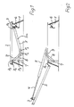
- Fig. 1 denotes a curb, on which a flap by means of a hinge about a stationary first axis of rotation P 0 is pivotable.
- a piston rod 4 of a Doppelhubzylinders 5 At the opposite end to the first axis of rotation P 0 engages the flap 2 via a locking element 3, a piston rod 4 of a Doppelhubzylinders 5 as a linear drive element.
- the pivotable connection of the piston rod to the locking element 3 and the flap 2 is designated P 1 .
- the locking element cooperates with a locking bracket 6 which is fixedly mounted inside the curb, such that upon actuation of the piston rod 4, see Fig. 2, an unlocking takes place.
- a bracket 7 is fixed to the inside of the curb, which protrudes approximately at right angles and perpendicularly downward with respect to the closed flap 2.
- the bracket 7 serves to support a support lever 8 and a reversing lever 9, whose one end with a fixed pivot point P 2 closer to the stationary first axis of rotation of the flap is arranged as a fixed pivot axis P 3 of the support lever 8, wherein the fixed pivot point P 2 and the fixed pivot axis P 3 are arranged here along a vertical line.
- the support lever 8 is arranged with an opposite to the stationary pivot axis P 3 end to the Doppelhubzylinder 5 and that in the central axis 5a of this Doppelhubzylinders 5.
- P 5 forms the first pivot axis of the Doppelhubzylinders 5 on the support lever 8, in the region of one end the double-stroke cylinder is arranged opposite to the pivotable connection point P 1 on the locking element 3 or the flap 2.
- the pivot axis P 4 of the reversing lever 9 is arranged.
- the pivot axis P 4 is referred to as the third pivot axis, because at least one second pivot axis is present at the pivotable connection point P 1 .
- the locking element 3 Upon actuation of the Doppelhubzylinders in the alarm position (see Figure 2), the locking element 3 is unlocked by the piston rod 4 of the locking console 6 and the flap 2 is raised and pivoted, with only forces on the first axis of rotation P 0 on the hinge of the flap and on the pivotable connection point P 1 are introduced into the flap, which is thus little burden.
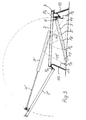
- the kinematics of the arrangement of the flap 2 of the Doppelhubzylinders 5 of the support lever 8 and the reversing lever 9 is formed so that during the pivotal movement of the flap 2, the first pivot axis P 5 of Doppelhubzylinders 5 about the stationary second pivot axis P 3 of the support lever 8 describes a circular path, which intersects with a circular path which describes the point P 4 as the third pivot axis of the Doppelhubzylinders at one end of the reversing lever 9 about its stationary pivot axis P 2 on the console 7. Segments of this circular path are shown in Fig. 3 with dotted lines.
- a first variant which allows the joint arrangement according to the invention, it is assumed from Fig. 3 of a top frame with a bracket 11 which is located on the same side inside of the top frame on which above the first axis of rotation P 0 of the flap 2 is arranged so do not continuously extend from the area of this first axis of rotation P 0 down as the console 7 in Figs. 1 and 2.
- a locking bracket is in the top frame 10 of FIG. 3 on the opposite side inside 12 extends downward.
- FIG. 3 In the first variant of FIG. 3 is a support lever 13, whose central axis is shown with a dash-dot line, pivotally between a first pivot axis P 5 in the central axis of the Doppelhubzylinders 5 as a linear drive element on the one hand and the stationary second pivot axis P 3 , in the Console 11 is mounted below at a vertical distance from the first axis of rotation P 0 , arranged.
- a likewise indicated only by its center line dash-dotted lever 14 is pivotable on the one hand about a third pivot axis P 4 on the Doppelhubzylinder 5 and on the other hand about a fixed pivot point P 2 below in the locking console 12th
- the double-stroke cylinder 5 When the double-stroke cylinder 5 is actuated, it in turn releases with its piston rod 4 a locking element 3 from the locking console 12 and pushes or pivots the flap 2 from the closed horizontal position into the wide-open alarm position of the flap 2 '.
- the kinematics in turn, as in the basic form so that the point P, a circle segment around the point P 2 describes until the bellcrank is in the alarm position 14 '.
- the point P 5 which represents the first pivot axis, describes a circular segment about the fixed second pivot axis P 3 of the support lever 13, which is designated in the alarm position by 13 '. Both circle segments intersect.
- FIG. 4 In the second variant of FIG. 4 is located within a top frame 15 on the opposite to the stationary first axis of rotation of the flap 2 side inside a console 16 which extends from an upper part designed for locking downwards, where in turn a fixed pivot point P. 2 a reversing lever 17 is pivotally mounted. At its opposite end, the reversing lever 17 is in turn arranged on the third pivot axis P 4 of the Doppelhubzylinders as a linear drive element, and indeed at its end, which is opposite to the locking element 3.
- a support lever 18 is further arranged from the end of the Doppelhubzylinders 5 about the first pivot axis of the Doppelhubzylinders P 5 to a support lever 18 which is in the drawn basic position, the closed position of the flap 2, parallel to the Doppelhubzylinder.
- To the first pivot axis P 5 opposite end of the support lever is mounted in a stationary second pivot axis P 3 , which is here perpendicular to the fixed pivot point P 2 of the reversing lever in the console 16.
- This embodiment is thus characterized by the fact that the console 16 opposite the inside of the attachment frame 15 no console or the like may be arranged must, to the reversing lever 17 or the support lever 18 at each store one end stationary. Nevertheless, the principle is Same kinematics with respect to the movement of the flap 2 in achieves the unillustrated wide open alarm position, as shown in Fig. 3.
Landscapes
- Engineering & Computer Science (AREA)
- General Engineering & Computer Science (AREA)
- Mechanical Engineering (AREA)
- Emergency Management (AREA)
- Chemical & Material Sciences (AREA)
- Public Health (AREA)
- Combustion & Propulsion (AREA)
- Business, Economics & Management (AREA)
- Health & Medical Sciences (AREA)
- Transmission Devices (AREA)
- Power-Operated Mechanisms For Wings (AREA)
- Holders For Apparel And Elements Relating To Apparel (AREA)
- Catching Or Destruction (AREA)
- Air-Flow Control Members (AREA)
- Harvester Elements (AREA)
- Mechanically-Actuated Valves (AREA)
Abstract
Description
Die Erfindung betrifft eine Gelenkanordnung zur Betätigung einer Klappe oder dergleichen nach dem Oberbegriff des Anspruchs 1.The invention relates to a hinge assembly for actuation a flap or the like according to the preamble of the claim 1.
Die Gelenkanordnung kann bei Lichtkuppeln mit einem Aufsatzkranz eingesetzt werden, in dem eine feststehende Konsole montiert ist. An dem Aufsatzkranz ist ein Lüfterrahmen beweglich mit Scharnieren angebracht. In einer Ausführungsform kann die Lichtkuppel auf dem Lüfterrahmen aufliegen; in einer anderen Ausführungsform ist der Lüfterrahmen als Einfaßrahmen für die Lichtkuppel ausgebildet. Weiterhin kann die Erfindung für Lichtbänder, sogenannte Lichtstraßen eingesetzt werden, die eine Zarge anstelle eines Aufsatzkranzes aufweisen. Mit der Gelenkanordnung können Einzel- oder Doppelklappen aus Blech betätigt werden oder aber auch Lamellen eines Lamellenlüfters. Generell wird mit der Gelenkanordnung ein dreh- bzw. kippbares Element, wie z. B. eine Klappe oder eine Lamelle betätigt.The joint arrangement can in light domes with a curb be used in which a fixed console is mounted. On the curb a fan frame is movable attached with hinges. In one embodiment the dome lights rest on the fan frame; in another Embodiment is the fan frame as a border frame for formed the dome light. Furthermore, the invention for Lichtbänder, so-called light streets are used, the have a frame instead of a curb. With the Joint arrangement can be single or double flaps made of sheet metal be actuated or slats of a lamellar fan. Generally, with the hinge assembly a rotatable or tiltable Element, such as B. actuates a flap or a blade.
Die Gelenkanordnung soll die Anforderung für RWA-Anlage, d.h. Rauch- und Wärmeabzugsanlagen erfüllen, bei denen eine Rauchabzugsklappe in Alarmstellung einen großen Öffnungswinkel von etwa 165 ° erreichen soll.The hinge assembly is intended to meet the requirement for SHE system, i. Smoke and heat exhaust systems meet, where a smoke vent in alarm position a large opening angle of should reach about 165 °.
Eine bekannte Gelenkanordnung der eingangs genannten Gattung ist vollständig selbständig in und aus einer solchen Alarmstellung betätigbar, wobei das Öffnen und Schließen einer Klappe über einen gesamten großen Schwenkbereich bis etwa 165° betragen kann, wozu nur ein Antriebselement benötigt wird.A known joint arrangement of the type mentioned is completely independent in and out of such an alert operable, with the opening and closing of a Flap over a whole large swivel range to about 165 ° may be, for which only a drive element is needed.
Bei einer solchen bekannten Gelenkanordnung ist ein Ende eines linearen Antriebselements an einer von einer ortsfesten ersten Drehachse einer Klappe oder Kuppel entfernten Stelle der Klappe schwenkbar an einem Traversenteil der Klappe angebracht. Andererseits ist das lineare Antriebselement um eine erste Schwenkachse schwenkbar an einem Stützhebel angebracht, der seinerseits um eine ortsfeste zweite Schwenkachse in der Nähe der Drehachse der Klappe schwenkbar ist. Dabei liegt die erste Schwenkachse etwa in der Mitte der Längsausdehnung des Stützhebels. Ein zusätzlicher Umlenkhebel ist mit einem ersten Ende an einem zu der zweiten Schwenkachse entfernten Ende des Stützhebels schwenkbar angeordnet. Ein zweites Ende des Umlenkhebels greift schwenkbar an dem Traversenteil der Klappe im Abstand zu deren Drehachse und zu der Anbringungsstelle des ersten Endes des Antriebselements an (EP 0 443 050 B1). Diese Gelenkanordnung zeichnet sich gegenüber anderen Gelenkanordnungen durch eine verhältnismäßig raumsparende Lage des linearen Antriebselements, insbesondere eines Hubzylinders, aus. Bei einer weniger raumsparenden Variante der Gelenkanordnung mit nur einem linearen Antriebselement ist an dessen erster Schwenkachse der zusätzliche Umlenkhebel mit einem ersten Ende schwenkbar angeordnet, dessen zweites Ende an dem Traversenteil der Klappe im Abstand zu deren Drehachse und zu der Anbringungsstelle des ersten Endes des Antriebselements angreift. - Bei einer weiteren Variante der Gelenkanordnung mit nur einem einzigen linearen Antriebselement ist dieses mit seinem zweiten Ende um eine ortsfeste dritte Schwenkachse schwenkbar, die mit einem ortsfesten zweiten Traversenteil bzw. Traversenunterteil in fester Verbindung stehend tiefer sowie von der ersten Drehachse, um welchen die Klappe schwenkbar ist, entfernter als die zweite Schwenkachse angeordnet ist, um welche der Stützhebel schwenkbar ist. Die Anordnung ist derart gestaltet, daß die Entfernung der dritten Schwenkachse von der ersten Schwenkachse größer bemessen ist als die Entfernung des Drehpunkts des Umlenkhebels am Traversenteil von der ersten Drehachse und größer ist als die Entfernung der zweiten Schwenkachse von der ersten Drehachse. - Allen diesen bekannten Gelenkanordnungen ist gemeinsam, daß durch das lineare Antriebselement an dem Traversenteil zusätzliche Querkräfte eingeleitet werden, welche eine entsprechend feste Traverse erfordern. In such a known hinge assembly is an end of a linear drive element at one of a stationary first Rotary axis of a flap or dome remote location of the flap pivotally mounted on a truss part of the flap. On the other hand, the linear drive element is a first Swivel axis pivotally mounted on a support lever, the in turn around a fixed second pivot axis nearby the axis of rotation of the flap is pivotable. This is the first Swivel axis approximately in the middle of the longitudinal extent of the support lever. An additional bellcrank is with a first end at an end remote from the second pivot axis of the Support lever arranged pivotally. A second end of the reversing lever engages pivotally on the truss part of the flap at a distance to its axis of rotation and to the mounting location of the first end of the drive element (EP 0 443 050 B1). These Joint arrangement is distinguished from other joint arrangements by a relatively space-saving position of the linear Drive elements, in particular a lifting cylinder, off. In a less space-saving variant of the joint arrangement with only one linear drive element is at the first Pivot axis of the additional lever with a first end pivotally arranged, the second end of the truss part the flap at a distance to its axis of rotation and to the mounting location the first end of the drive element attacks. - In a further variant of the joint arrangement with only a single linear drive element is this with its second end about a fixed third pivot axis swiveling, with a fixed second truss part or truss bottom in solid connection standing deeper as well as from the first axis of rotation about which the flap pivots is located more distant than the second pivot axis is about which the support lever is pivotable. The order is designed such that the distance of the third pivot axis is dimensioned larger than the first pivot axis Removal of the pivot point of the reversing lever on the truss part from the first axis of rotation and is greater than the distance of the second pivot axis of the first axis of rotation. - All these Known joint arrangements have in common that by the linear Drive element on the truss part additional lateral forces be initiated, which is a correspondingly fixed Traverse require.
Der Erfindung liegt daher die Aufgabe zugrunde, eine Gelenkanordnung der eingangs genannten Gattung so auszubilden, daß diese an der Klappe, Lamelle oder dergleichen, an der das lineare Antriebselement angreift, keine zusätzlichen Querkräfte einleitet, so daß die Traverse bzw. ein Traversenunterteil nicht erforderlich ist. Damit soll auch eine leichte, materialsparende Bauweise des von der linearen Antriebsvorrichtung und Gelenkanordnung betätigten Elements ermöglicht werden.The invention is therefore based on the object, a joint assembly of the type mentioned above in such a way that this on the flap, lamella or the like, at the linear drive element attacks, no additional lateral forces initiates, so that the traverse or a truss bottom is not required. This should also be a light, material-saving Construction of the linear drive device and hinge assembly actuated element.
Diese Aufgabe wird erfindungsgemäß durch die Ausbildung der Gelenkanordnung mit den in dem Anspruch 1 angegebenen Merkmalen gelöst.This object is achieved by the training of Joint arrangement with the features specified in claim 1 solved.
Die Gelenkanordnung mit diesen Merkmalen kann so ausgebildet werden, daß sie auch zur Betätigung von Rauchabzugsklappen in RWA-Anlagen einen großen Öffnungswinkel bei vollständig selbständigen Öffnung und Schließen ermöglicht, und zwar ohne auf die Rauchabzugsklappe zusätzliche Querkräfte aufzubringen, die sonst von einem Traversenteil abzufangen sind. Es werden lediglich Kräfte in die Klappe bzw. das betätigbare Element an dessen Drehachse bzw. Scharnier sowie an der schwenkbar ausgeführten Anbringungsstelle des linearen Antriebselements an der Klappe, wobei letztere Stelle zu der Drehachse im wesentlichen entgegengesetzt ist, eingeleitet. Reaktionskräfte des linearen Antriebselements werden über den Umlenkhebel und den Stützhebel nur in einem ortsfesten Drehpunkt des Umlenkhebels bzw. einer ortsfeste zweite Schwenkachse des Stützhebels eingeleitet. Die erfindungsgemäße Gelenkanordnung kann in ihrem Abmessungen flexibel an gegebene Einsatzforderungen angepaßt werden, solange die Merkmale des kennzeichnenden Teils des Anspruchs 1 erfüllt sind. Zu der Gestaltung der Lagerstelle des zweiten Endes des Umlenkhebels an einem festen Drehpunkt sowie der dritten Schwenkachse, um welche der Umlenkhebel an dem linearen Antriebselement schwenkbar ist, muß beachtet werden, daß die erste Schwenkachse des linearen Antriebselements an dem Stützhebel sowie die dritte Schwenkachse, um welche der Umlenkhebel an dem linearen Antriebselement schwenkbar ist, bei Betätigung des linearen Antriebselements kreisförmige Bewegungsbahnen beschreiben, die sich kreuzen und eine resultierende Drehung des linearen Antriebselements hervorrufen. Dabei kann sich außerdem das Antriebselement linear verschieben, und zwar wird im Falle einer Klappe, an welche das lineare Antriebselement, insbesondere eine Kolbenstange eines Druckluftzylinders im geschlossenen Zustand von unten angreift, bei der Drehung des linearen Antriebselements dieses gleichzeitig nach oben bewegt. Die trotz dieser Kinematik unkompliziert realisierbare Gelenkanordnung hat den weiteren Vorteil einer sehr flachen Bauweise, so daß die Gelenkanordnung mit linearem Antriebselement nicht oder nur sehr wenig aus einem normalen Aufsatzrahmen oder Aufsatzkranz, an dem eine Klappe angelenkt ist, nach unten herausragt. Je nach Platzverhältnissen oder Festigkeit der Aufsatzrahmen oder Zargen, in welche die Gelenkanordnung mit dem Antriebselement eingesetzt werden soll, kann eine optimale Gestaltung erreicht werden.The hinge assembly with these features can be designed be that they are also used to operate smoke flaps in SHE systems have a large opening angle with completely independent Opening and closing allows, without being on the smoke damper flap to apply additional lateral forces, the otherwise intercept by a truss part. It will only Forces in the flap or the actuatable element the axis of rotation or hinge as well as on the swivel executed Location of the linear drive element on the Flap, the latter location substantially parallel to the axis of rotation is opposite, initiated. Reaction forces of the linear Drive elements are via the lever and the support lever only in a fixed pivot point of the reversing lever or a stationary second pivot axis of the support lever initiated. The hinge assembly according to the invention may be in their dimensions adapted flexibly to given operational requirements as long as the characteristics of the characterizing part of the Claim 1 are satisfied. To the design of the depository the second end of the reversing lever at a fixed pivot point and the third pivot axis about which the bellcrank the linear drive element is pivotable must be observed be that the first pivot axis of the linear drive element on the support lever and the third pivot axis to which of the lever on the linear drive element is pivotable when operating the linear drive element describe circular trajectories that intersect and cause a resultant rotation of the linear drive element. In addition, the drive element can be linear move, in the case of a flap, to which the linear drive element, in particular a piston rod a compressed air cylinder in the closed state from below engages, during the rotation of the linear drive element this simultaneously moved up. The despite this kinematics uncomplicated realizable joint arrangement has the other Advantage of a very flat design, so that the hinge assembly with linear drive element not or only very little from a normal top frame or curb on which a flap is articulated, protruding downwards. Depending on Space or strength of the top frame or Frames in which the hinge assembly with the drive element can be used, an optimal design can be achieved become.
Die erforderliche, oben geschilderte Kinematik der Gelenkanordnung
wird gemäß Anspruch 2 insbesondere dadurch erzielt,
daß die dritte Schwenkachse, um welche das lineare Antriebselement
an dem Umlenkhebel schwenkbar ist, näher zu dem Ende
des linearen Antriebselements, welches der Klappe abgewandt
ist, angeordnet ist als die erste Schwenkachse, um welche der
Stützhebel an dem linearen Antriebselement schwenkbar ist.
Daraus ergibt sich auch, daß der Umlenkhebel über eine größere
Länge an dem linearen Antriebselement drehbar gelagert ist als
der Stützhebel. Es sei an dieser Stelle bemerkt, daß der Umlenkhebel
und der Stützhebel auch als erster Schwinghebel und
zweiter Schwinghebel bezeichnet werden können.The required, above-described kinematics of the joint arrangement
is achieved according to
Eine einfache Grundform der Gelenkanordnung zeichnet sich
gemäß Anspruch 3 dadurch aus, daß das zweite Ende des Umlenkhebels
an den ortsfesten Drehpunkt näher bei der ortsfesten
ersten Drehachse der Klappe als die ortsfeste zweite Schwenkachse
des Stützhebels und vorzugsweise unter der ortsfesten
zweiten Schwenkachse des Stützhebels gelagert ist.A simple basic form of the joint arrangement is apparent
according to
Diese Ausführungsform empfiehlt sich vor allem bei einer feststehenden Konsole in einem Aufsatzkranz.This embodiment is especially recommended for a fixed Console in a curb.
Unter Nutzung dieser Konsole ist gemäß Anspruch 4 der ortsfeste
Drehpunkt des zweiten Endes des Umlenkhebels an der
feststehenden Konsole, die in der Nähe der Drehachse der Klappe
von dieser in deren geschlossener Stelle vorzugsweise im
wesentlichen rechtwinklig zu dieser absteht, im wesentlichen
unterhalb der Drehachse der Klappe angeordnet. Die ortsfeste
zweite Schwenkachse des Stützhebels an der Konsole ist im
wesentlichen unterhalb des ortsfesten Drehpunkts des zweiten
Endes des Umlenkhebels an der Konsole angebracht.Using this console is fixed according to
In besonders vorteilhafter Weise ist keine Führung parallel zu
dem linearen Antriebselement erforderlich, wenn gemäß Anspruch
5 die dritte Schwenkachse an dem ersten Ende des Umlenkhebels
und die erste Schwenkachse des linearen Antriebselements an
dem Stützhebel in der Mittelachse des linearen Antriebselements
liegen.In a particularly advantageous manner, no guidance is parallel to
the linear drive element required if according to
Gemäß Anspruch 6 empfiehlt sich der Einsatz eines linearen
Antriebselements, welches geeignet ist, die durch die Gelenkanordnung
erzeugten Seitenkräfte bzw. Biegekräfte aufzunehmen.According to
Da an dem betätigbaren Element, an dem ein Ende des linearen
Antriebselements angreift, hingegen keine zusätzlichen Querkräfte
durch die Gelenkanordnung eingeführt werden, kann gemäß
Anspruch 7 dieses betätigbare Element bzw. die Klappe konstruktiv
einfach und massearm an ihrem zu dem ortsfesten Drehpunkt
entfernten Ende unmittelbar, d.h. ohne Einfügung eines
Traversenteils mit dem linearen Antriebselement in schwenkbare
Verbindung gebracht werden.As on the actuatable element, at which one end of the linear
Drive element attacks, however, no additional lateral forces
can be introduced through the hinge assembly, according to
In einer besonders raumsparenden Gelenkanordnung befindet sich die dritte Schwenkachse, um welche das lineare Antriebselement schwenkbar ist, an dem einen Ende des Stützhebels. Im dem Falle, in dem ein Doppelhubzylinder als lineares Antriebselement verwendet wird, kann über die dritte Schwenkachse Druckluft zugeführt werden, ebenso über die erste Schwenkachse des linearen Antriebselements an dem Stützhebel.In a particularly space-saving hinge assembly is located the third pivot axis about which the linear drive element is pivotable, at one end of the support lever. In the Case in which a Doppelhubzylinder as a linear drive element can be used over the third pivot axis Compressed air are supplied, as well as the first Pivot axis of the linear drive element on the support lever.
Drei Ausführungsformen der Erfindung werden im folgenden anhand einer Zeichnung mit vier Figuren beschrieben, woraus sich weitere Merkmale und Vorteile ergeben. Es zeigen:
- Fig. 1
- in einer Seitenansicht teilweise geschnitten eine Grundform der Gelenkanordnung zur Betätigung einer Klappe mit einem Doppelhubzylinder in einer geschlossenen Grundstellung,
- Fig. 2
- in der gleichen Seitenansicht wie in Fig. 1 die Grundform der Gelenkanordnung in einer weit geöffneten Alarmstellung der Klappe,
- Fig. 3
- ebenfalls in einer Seitenansicht teilweise geschnitten eine erste Variante der Gelenkanordnung in der Grundstellung und in einer weit geöffneten Alarmstellung einer Klappe und
- Fig. 4
- in einer Seitenansicht teilweise geschnitten eine zweite Variante der Gelenkanordnung in der geschlossenen Grundstellung der Klappe.
- Fig. 1
- in a side view partially cut a basic shape of the hinge assembly for actuating a flap with a Doppelhubzylinder in a closed basic position,
- Fig. 2
- in the same side view as in Fig. 1, the basic shape of the hinge assembly in a wide-open alarm position of the flap,
- Fig. 3
- also in a side view partially cut a first variant of the hinge assembly in the normal position and in a wide open alarm position of a flap and
- Fig. 4
- in a side view partially cut a second variant of the hinge assembly in the closed position of the flap.
In Fig. 1 ist mit 1 ein Aufsatzkranz bezeichnet, auf dem eine
Klappe mittels eines Scharniers um eine ortsfeste erste Drehachse
P0 schwenkbar ist. An dem entgegengesetzten Ende zu der
ersten Drehachse P0 greift an der Klappe 2 über ein Verriegelungselement
3 eine Kolbenstange 4 eines Doppelhubzylinders 5
als lineares Antriebselement an. Die schwenkbare Verbindung
der Kolbenstange an dem Verriegelungselement 3 bzw. der Klappe
2 ist mit P1 bezeichnet. Das Verriegelungselement wirkt mit
einer Verriegelungskonsole 6 zusammen, die innen an dem Aufsatzkranz
fest angebracht ist, derart, daß bei Betätigung der
Kolbenstange 4, siehe Fig. 2, eine Entriegelung erfolgt. In Fig. 1, 1 denotes a curb, on which a flap by means of a hinge about a stationary first axis of rotation P 0 is pivotable. At the opposite end to the first axis of rotation P 0 engages the
An dem zu der schwenkbaren Verbindungsstelle P1 gegenüberliegenden
Seite, nämlich in der Nähe der ersten Drehachse P0, ist
innen an dem Aufsatzkranz eine Konsole 7 befestigt, die bezüglich
der geschlossenen Klappe 2 annähernd rechtwinklig und
lotrecht nach unten absteht. Die Konsole 7 dient zur Lagerung
eines Stützhebels 8 sowie eines Umlenkhebels 9, dessen eines
Ende mit einem ortsfesten Drehpunkt P2 näher an der ortsfesten
ersten Drehachse der Klappe angeordnet ist als eine ortsfeste
Schwenkachse P3 des Stützhebels 8, wobei der ortsfeste Drehpunkt
P2 und die ortsfeste Schwenkachse P3 hier längs einer
lotrechten Linie angeordnet sind. Der Stützhebel 8 ist mit
einem zu der ortsfesten Schwenkachse P3 entgegengesetzten Ende
an dem Doppelhubzylinder 5 angeordnet und zwar in der Mittelachse
5a dieses Doppelhubzylinders 5. P5 bildet dabei die erste
Schwenkachse des Doppelhubzylinders 5 an dem Stützhebel 8, die
im Bereich des einen Endes des Doppelhubzylinders angeordnet
ist, der der schwenkbaren Verbindungsstelle P1 an dem Verriegelungselement
3 bzw. der Klappe 2 gegenüberliegt. Noch näher an
dem Ende des Doppelhubzylinders 5 als die erste Schwenkachse
P5 ist die Schwenkachse P4 des Umlenkhebels 9 angeordnet. Die
Schwenkachse P4 wird als dritte Schwenkachse bezeichnet, weil
mindestens eine zweite Schwenkachse an der schwenkbaren Verbindungsstelle
P1 vorliegt.At the opposite side to the pivotable connection point P 1 , namely in the vicinity of the first axis of rotation P 0 , a
Bei Betätigung des Doppelhubzylinders in die Alarmstellung
(siehe Fig 2) wird das Verriegelungselement 3 durch die Kolbenstange
4 von der Verriegelungskonsole 6 entriegelt und die
Klappe 2 angehoben und geschwenkt, wobei nur Kräfte an der
ersten Drehachse P0 an dem Scharnier der Klappe und an der
schwenkbaren Verbindungsstelle P1 in die Klappe eingeleitet
werden, die somit wenig belastet wird. Die Kinematik der Anordnung
der Klappe 2 des Doppelhubzylinders 5 des Stützhebels
8 und des Umlenkhebels 9 ist so ausgebildet, daß bei der
Schwenkbewegung der Klappe 2 die erste Schwenkachse P5 des
Doppelhubzylinders 5 um die ortsfeste zweite Schwenkachse P3
des Stützhebels 8 eine Kreisbahn beschreibt, die sich mit
einer Kreisbahn schneidet, welche der Punkt P4 als dritte
Schwenkachse des Doppelhubzylinders an dem einen Ende des
Umlenkhebels 9 um dessen ortsfeste Schwenkachse P2 an der Konsole
7 beschreibt. Segmente dieser kreisförmigen Bahn sind in
Fig. 3 mit strichpunktierten Linien dargestellt.Upon actuation of the Doppelhubzylinders in the alarm position (see Figure 2), the locking
Als erste Variante, welche die erfindungsgemäße Gelenkanordnung
zuläßt, wird gemäß Fig. 3 von einem Aufsatzrahmen mit
einer Konsole 11 ausgegangen, die sich auf derselben Seite
innen an dem Aufsatzrahmen befindet, an der über ihr die erste
Drehachse P0 der Klappe 2 angeordnet ist, sich also nicht aus
dem Bereich dieser ersten Drehachse P0 durchgehend nach unten
erstreckt wie die Konsole 7 in den Fig. 1 und 2. Andererseits
ist in dem Aufsatzrahmen 10 gemäß Fig. 3 auf der gegenüberliegenden
Seite innen eine Verriegelungskonsole 12 nach unten
verlängert.As a first variant, which allows the joint arrangement according to the invention, it is assumed from Fig. 3 of a top frame with a
Es sei an dieser Stelle bemerkt, daß in sämtlichen Figuren übereinstimmende Teile gleiche Bezugszeichen tragen.It should be noted at this point that in all figures Matching parts bear the same reference numerals.
In der ersten Variante gemäß Fig. 3 ist ein Stützhebel 13,
dessen Mittelachse mit einer strichpunktierten Linie dargestellt
ist, schwenkbar zwischen einer ersten Schwenkachse P5 in
der Mittelachse des Doppelhubzylinders 5 als linearem Antriebselement
einerseits und der ortsfesten zweiten
Schwenkachse P3, die in der Konsole 11 unten in einem lotrechten
Abstand zu der ersten Drehachse P0 gelagert ist, angeordnet.
Ein ebenfalls nur mit seiner Mittellinie strichpunktiert
angedeuteter Umlenkhebel 14 ist einerseits um eine dritte
Schwenkachse P4 an dem Doppelhubzylinder 5 schwenkbar sowie
andererseits um einen ortsfesten Drehpunkt P2 unten in der
Verriegelungskonsole 12.In the first variant of FIG. 3 is a
Wenn der Doppelhubzylinder 5 betätigt wird, löst er wiederum
mit seiner Kolbenstange 4 ein Verriegelungselement 3 von der
Verriegelungskonsole 12 und drückt bzw. schwenkt die Klappe 2
aus der geschlossenen waagerechten Stellung in die weit geöffnete
Alarmstellung der Klappe 2'. Die Kinematik ist wiederum
wie bei der Grundform so, daß der Punkt P, ein Kreissegment
um den Punkt P2 beschreibt, bis sich der Umlenkhebel in
der Alarmstellung 14' befindet. Analog dazu beschreibt der
Punkt P5, der die erste Schwenkachse darstellt, ein Kreissegment,
um die ortsfeste zweite Schwenkachse P3 des Stützhebels
13, der in der Alarmstellung mit 13' bezeichnet ist. Beide
Kreissegmente schneiden sich.When the double-
Bei der zweiten Variante gemäß Fig. 4 befindet sich innerhalb
eines Aufsatzrahmens 15 an der zu der ortsfesten ersten Drehachse
der Klappe 2 entgegengesetzten Seite innen eine Konsole
16, die sich von einem oberen zur Verriegelung ausgebildeten
Teil nach unten erstreckt, wo wiederum ein ortsfester Drehpunkt
P2 eines Umlenkhebels 17 schwenkbar gelagert ist. An
seinem entgegengesetzten Ende ist der Umlenkhebel 17 wiederum
an der dritten Schwenkachse P4 des Doppelhubzylinders als
lineares Antriebselement angeordnet, und zwar an dessen Ende,
welches dem Verriegelungselement 3 entgegengesetzt ist.In the second variant of FIG. 4 is located within a top frame 15 on the opposite to the stationary first axis of rotation of the
Ein Stützhebel 18 ist weiter von dem Ende des Doppelhubzylinders
5 um die erste Schwenkachse des Doppelhubzylinders P5 an
einem Stützhebel 18 angeordnet, der in der gezeichneten
Grundstellung, der geschlossenen Stellung der Klappe 2, parallel
zu dem Doppelhubzylinder liegt. Zu der ersten Schwenkachse
P5 entgegengesetzten Ende ist der Stützhebel in einer
ortsfesten zweiten Schwenkachse P3 gelagert, die hier lotrecht
über dem ortsfesten Drehpunkt P2 des Umlenkhebels in der Konsole
16 liegt.A
Diese Ausführungsform zeichnet sich also dadurch aus, daß an
der der Konsole 16 gegenüberliegenden Innenseite des Aufsatzrahmens
15 keinerlei Konsole oder dergleichen angeordnet sein
muß, um den Umlenkhebel 17 oder den Stützhebel 18 an jeweils
einem Ende ortsfest zu lagern. Trotzdem wird die grundsätzlich
gleiche Kinematik hinsichtlich der Bewegung der Klappe 2 in
die nicht dargestellte weit geöffnete Alarmstellung erzielt,
wie in Fig. 3 dargestellt.This embodiment is thus characterized by the fact that
the console 16 opposite the inside of the attachment frame
15 no console or the like may be arranged
must, to the reversing
Claims (9)
- Articulated arrangement for the actuation of a flap or the like, in particular a smoke exhaust flap or dome, which can be pivoted around a positionally fixed, first rotation axis (P0) from a closed position to an alarm position and back again, with a linear drive element (5) one end of which is in hinged connection at a point on the flap a distance away from the rotation axis and which, at the other end, is attached to pivot about a first pivoting axis (P5) on a support lever (8), which for its part can pivot about a positionally fixed, second pivoting axis (P3) a distance away from and in particular below the positionally fixed, first rotation axis of the flap, and an additional displacement lever (9, 14, 17) is arranged at a first end to pivot about a third pivoting axis (P4) on the drive element (5),
characterised in that
a second end of the displacement lever (9, 14, 17) is mounted on a fixed pivot point (P2), in such manner that when the linear drive element (5) is actuated, the first pivoting axis (P5) of the linear drive element (5) on the support lever (8, 13, 18) and the third pivoting axis (P4), about which the displacement lever (9, 14, 17) can pivot on the linear drive element (5), describe circular movement paths which cross one another and bring about a resultant rotation of the linear drive element (5). - Articulated arrangement according to Claim 1,
characterised in that
the third pivoting axis (P4), about which the linear drive element can pivot on the displacement lever (9, 14, 17), is arranged closer to the end of the linear drive element that is away from the flap, than is the first pivoting axis (P5) about which the support lever (8, 13, 18) can pivot on the linear drive element. - Articulated arrangement according to Claims 1 or 2,
characterised in that
the second end of the displacement lever (8) is mounted at the positionally fixed rotation point (P2) closer to the positionally fixed, first rotation axis (P0) of the flap (2) than is the positionally fixed second pivoting axis (P3) of the support lever (8) and preferably under it. - Articulated arrangement according to Claim 3,
characterised in that
the positionally fixed rotation point (P2) of the second end of the displacement lever (9) on a fixed bracket (7), which extends in the vicinity of the rotation axis (P0) of the flap (2) from the latter in its closed position preferably essentially at right-angles, is arranged essentially under the rotation axis (P0) of the flap (2), and the positionally fixed second pivoting axis (P3) of the support lever (8) on the bracket (7) is positioned essentially below the positionally fixed rotation point (P2) of the second end of the displacement lever (9) on the console (7). - Articulated arrangement according to any of the preceding claims,
characterised in that
the third pivoting axis (P4) of the first end of the displacement lever (9, 14, 17) and the first pivoting axis of the linear drive element on the support lever (8, 13, 18) lie on the central axis (5a) of the linear drive element. - Articulated arrangement according to any of the preceding claims,
characterised in that
it comprises a linear drive element that is suitable for absorbing lateral forces. - Articulated arrangement according to any of the preceding claims,
characterised in that
at its end away from the positionally fixed rotation point (P0), the flap (2) is in pivoting connection with the linear drive element directly, i.e. without the interposition of a crosspiece. - Articulated arrangement according to any of the preceding claims,
characterised in that
as the linear drive element, a double lifting cylinder (5) is provided. - Articulated arrangement according to Claims 3 or 4,
characterised in that
the third pivoting axis (P4), about which the linear drive element can pivot on the displacement lever (9, 14, 17), is located at the end of the linear drive element.
Applications Claiming Priority (2)
| Application Number | Priority Date | Filing Date | Title |
|---|---|---|---|
| DE19830678A DE19830678C2 (en) | 1998-07-09 | 1998-07-09 | Joint arrangement for actuating a flap or the like |
| DE19830678 | 1998-07-09 |
Publications (3)
| Publication Number | Publication Date |
|---|---|
| EP0971091A2 EP0971091A2 (en) | 2000-01-12 |
| EP0971091A3 EP0971091A3 (en) | 2003-06-11 |
| EP0971091B1 true EP0971091B1 (en) | 2004-05-19 |
Family
ID=7873452
Family Applications (1)
| Application Number | Title | Priority Date | Filing Date |
|---|---|---|---|
| EP99113108A Expired - Lifetime EP0971091B1 (en) | 1998-07-09 | 1999-07-07 | Articulated arrangement for actuating a flap or the like |
Country Status (5)
| Country | Link |
|---|---|
| EP (1) | EP0971091B1 (en) |
| AT (1) | ATE267327T1 (en) |
| DE (2) | DE19830678C2 (en) |
| ES (1) | ES2217650T3 (en) |
| PL (1) | PL193843B1 (en) |
Cited By (1)
| Publication number | Priority date | Publication date | Assignee | Title |
|---|---|---|---|---|
| DE102006018485A1 (en) * | 2006-04-19 | 2007-10-25 | Andreas Grasl | Joint arrangement for actuating a flap, in particular smoke exhaust flap |
Families Citing this family (6)
| Publication number | Priority date | Publication date | Assignee | Title |
|---|---|---|---|---|
| DK176087B1 (en) | 2000-09-29 | 2006-05-22 | Vkr Holding As | Window with a maneuver for opening and closing it and a maneuver for such a window |
| DE10240039A1 (en) * | 2002-08-27 | 2004-03-04 | Suspa Holding Gmbh | Openable flap, in particular flue gas flap and opening mechanism therefor |
| PL210644B1 (en) * | 2006-01-23 | 2012-02-29 | Rewa Społka Z Ograniczoną Odpowiedzialnością | The opening-closing mechanism of the desmoking cover |
| DE102007041383B4 (en) | 2007-08-31 | 2009-10-22 | K + G Pneumatik Gmbh | Smoke and heat extraction and ventilation device comprising smoke and heat extraction and ventilation devices, each with a motor drive |
| FR2946079B1 (en) * | 2009-05-27 | 2015-10-09 | Souchier | DEVICE SUITABLE FOR OPENING A VANTAIL. |
| CN108301724B (en) * | 2018-01-18 | 2019-05-07 | 北京北方车辆集团有限公司 | A kind of lower turning type tail gate actuator design method |
Family Cites Families (4)
| Publication number | Priority date | Publication date | Assignee | Title |
|---|---|---|---|---|
| DE3143318A1 (en) * | 1981-10-31 | 1983-05-19 | Josef 4815 Schloss Holte Fortmeier | Smoke and heat outlet device |
| DE3338092C3 (en) * | 1983-10-20 | 1994-08-04 | Eberspaecher J | DEVICE FOR THE EXHAUST OF SMOKE AND HEAT AND FOR THE VENTILATION AND EXHAUST OF CLOSED ROOMS |
| DE8912132U1 (en) * | 1989-10-12 | 1990-04-19 | Fa. Otto Grasl, 3452 Heiligeneich, At | |
| DE19601318C2 (en) * | 1996-01-16 | 1999-01-21 | Grescha Ges Mbh & Co Grefe & S | Opening mechanism for opening and closing smoke and heat flaps |
-
1998
- 1998-07-09 DE DE19830678A patent/DE19830678C2/en not_active Expired - Lifetime
-
1999
- 1999-07-07 AT AT99113108T patent/ATE267327T1/en active
- 1999-07-07 EP EP99113108A patent/EP0971091B1/en not_active Expired - Lifetime
- 1999-07-07 ES ES99113108T patent/ES2217650T3/en not_active Expired - Lifetime
- 1999-07-07 DE DE59909506T patent/DE59909506D1/en not_active Expired - Lifetime
- 1999-07-08 PL PL334269A patent/PL193843B1/en unknown
Cited By (2)
| Publication number | Priority date | Publication date | Assignee | Title |
|---|---|---|---|---|
| DE102006018485A1 (en) * | 2006-04-19 | 2007-10-25 | Andreas Grasl | Joint arrangement for actuating a flap, in particular smoke exhaust flap |
| DE102006018485B4 (en) * | 2006-04-19 | 2008-03-13 | Andreas Grasl | Joint arrangement for actuating a flap, in particular smoke exhaust flap |
Also Published As
| Publication number | Publication date |
|---|---|
| DE19830678A1 (en) | 2000-01-13 |
| DE19830678C2 (en) | 2000-11-30 |
| PL193843B1 (en) | 2007-03-30 |
| ES2217650T3 (en) | 2004-11-01 |
| EP0971091A3 (en) | 2003-06-11 |
| EP0971091A2 (en) | 2000-01-12 |
| ATE267327T1 (en) | 2004-06-15 |
| DE59909506D1 (en) | 2004-06-24 |
Similar Documents
| Publication | Publication Date | Title |
|---|---|---|
| EP1312742B1 (en) | Checking device for a tilting wing, in particular a pivoting-and-tilting wing of a window, door or the like, corresponding window and corresponding method for motor-driven and manual tilting | |
| EP0520343A1 (en) | Installation for opening and closing of a vehicle hood | |
| EP0555757A1 (en) | Hinge for a vehicle hood | |
| EP1688289B1 (en) | Device for the rotation of a part of a vehicle roof | |
| EP0222160B1 (en) | Operating device for a freight-loading door | |
| EP0933242B1 (en) | Driving device for vehicle top | |
| EP0971091B1 (en) | Articulated arrangement for actuating a flap or the like | |
| EP0443050B1 (en) | Assembly for the operation of a damper door | |
| DE102011085177B4 (en) | Drive system for a motor vehicle roof system | |
| EP1847672B1 (en) | Joint assembly for actuating a flap, in particular a smoke exhaust flap | |
| EP0021080B1 (en) | Lifting, sliding or swinging door or window | |
| DE19912893A1 (en) | Cabriolet vehicle with cover, having force-producing device engaging with multi-link pivot | |
| DE102007024742A1 (en) | Window or door with swinging - and tilting mountings, includes independent load relief mechanism with horizontal running surfaces for load-transmitting component | |
| DE202011004196U1 (en) | closure device | |
| WO2007076786A1 (en) | Masking device for vehicle roof systems comprising an openable cover | |
| EP0782509A1 (en) | Steering column switch with micro-switches, two working positions and a neutral position | |
| EP0620350B1 (en) | Fitting for a window or a door | |
| EP1170445A2 (en) | Checking device for a tilting or tilting and pivoting wing pivotably mounted to a frame | |
| DE102011015093A1 (en) | Box cover rear edge hinge for mounting in region of trailing edge of convertible top compartment cover of convertible vehicle, has arm attached to cover panel and another arm attached to console assembly | |
| EP2025844B1 (en) | Outward positioning device | |
| EP1176276A1 (en) | A self latching locking structure with adjustment possibility | |
| DE10254537A1 (en) | Window or door | |
| DE3111579A1 (en) | Turn-and-tilt window | |
| EP1231345B1 (en) | Controlled locking device and corner guide | |
| EP0226698A2 (en) | Locking device against wrong operation of actuating bars |
Legal Events
| Date | Code | Title | Description |
|---|---|---|---|
| PUAI | Public reference made under article 153(3) epc to a published international application that has entered the european phase |
Free format text: ORIGINAL CODE: 0009012 |
|
| AK | Designated contracting states |
Kind code of ref document: A2 Designated state(s): AT BE CH CY DE DK ES FI FR GB GR IE IT LI LU MC NL PT SE |
|
| AX | Request for extension of the european patent |
Free format text: AL;LT;LV;MK;RO;SI |
|
| PUAL | Search report despatched |
Free format text: ORIGINAL CODE: 0009013 |
|
| AK | Designated contracting states |
Designated state(s): AT BE CH CY DE DK ES FI FR GB GR IE IT LI LU MC NL PT SE |
|
| AX | Request for extension of the european patent |
Extension state: AL LT LV MK RO SI |
|
| 17P | Request for examination filed |
Effective date: 20030828 |
|
| GRAP | Despatch of communication of intention to grant a patent |
Free format text: ORIGINAL CODE: EPIDOSNIGR1 |
|
| RTI1 | Title (correction) |
Free format text: ARTICULATED ARRANGEMENT FOR ACTUATING A FLAP OR THE LIKE |
|
| AKX | Designation fees paid |
Designated state(s): AT BE CH CY DE DK ES FI FR GB GR IE IT LI LU MC NL PT SE |
|
| GRAS | Grant fee paid |
Free format text: ORIGINAL CODE: EPIDOSNIGR3 |
|
| GRAA | (expected) grant |
Free format text: ORIGINAL CODE: 0009210 |
|
| AK | Designated contracting states |
Kind code of ref document: B1 Designated state(s): AT BE CH CY DE DK ES FI FR GB GR IE IT LI LU MC NL PT SE |
|
| PG25 | Lapsed in a contracting state [announced via postgrant information from national office to epo] |
Ref country code: IE Free format text: LAPSE BECAUSE OF FAILURE TO SUBMIT A TRANSLATION OF THE DESCRIPTION OR TO PAY THE FEE WITHIN THE PRESCRIBED TIME-LIMIT Effective date: 20040519 Ref country code: FI Free format text: LAPSE BECAUSE OF FAILURE TO SUBMIT A TRANSLATION OF THE DESCRIPTION OR TO PAY THE FEE WITHIN THE PRESCRIBED TIME-LIMIT Effective date: 20040519 Ref country code: CY Free format text: LAPSE BECAUSE OF FAILURE TO SUBMIT A TRANSLATION OF THE DESCRIPTION OR TO PAY THE FEE WITHIN THE PRESCRIBED TIME-LIMIT Effective date: 20040519 |
|
| REG | Reference to a national code |
Ref country code: GB Ref legal event code: FG4D Free format text: NOT ENGLISH |
|
| REG | Reference to a national code |
Ref country code: CH Ref legal event code: NV Representative=s name: A. BRAUN, BRAUN, HERITIER, ESCHMANN AG PATENTANWAE Ref country code: CH Ref legal event code: EP |
|
| GBT | Gb: translation of ep patent filed (gb section 77(6)(a)/1977) |
Effective date: 20040519 |
|
| REG | Reference to a national code |
Ref country code: IE Ref legal event code: FG4D Free format text: GERMAN |
|
| REF | Corresponds to: |
Ref document number: 59909506 Country of ref document: DE Date of ref document: 20040624 Kind code of ref document: P |
|
| PG25 | Lapsed in a contracting state [announced via postgrant information from national office to epo] |
Ref country code: LU Free format text: LAPSE BECAUSE OF NON-PAYMENT OF DUE FEES Effective date: 20040707 |
|
| PG25 | Lapsed in a contracting state [announced via postgrant information from national office to epo] |
Ref country code: MC Free format text: LAPSE BECAUSE OF NON-PAYMENT OF DUE FEES Effective date: 20040731 |
|
| PG25 | Lapsed in a contracting state [announced via postgrant information from national office to epo] |
Ref country code: GR Free format text: LAPSE BECAUSE OF FAILURE TO SUBMIT A TRANSLATION OF THE DESCRIPTION OR TO PAY THE FEE WITHIN THE PRESCRIBED TIME-LIMIT Effective date: 20040819 Ref country code: DK Free format text: LAPSE BECAUSE OF FAILURE TO SUBMIT A TRANSLATION OF THE DESCRIPTION OR TO PAY THE FEE WITHIN THE PRESCRIBED TIME-LIMIT Effective date: 20040819 |
|
| REG | Reference to a national code |
Ref country code: SE Ref legal event code: TRGR |
|
| REG | Reference to a national code |
Ref country code: ES Ref legal event code: FG2A Ref document number: 2217650 Country of ref document: ES Kind code of ref document: T3 |
|
| ET | Fr: translation filed | ||
| REG | Reference to a national code |
Ref country code: IE Ref legal event code: FD4D |
|
| PLBE | No opposition filed within time limit |
Free format text: ORIGINAL CODE: 0009261 |
|
| STAA | Information on the status of an ep patent application or granted ep patent |
Free format text: STATUS: NO OPPOSITION FILED WITHIN TIME LIMIT |
|
| 26N | No opposition filed |
Effective date: 20050222 |
|
| PG25 | Lapsed in a contracting state [announced via postgrant information from national office to epo] |
Ref country code: PT Free format text: LAPSE BECAUSE OF NON-PAYMENT OF DUE FEES Effective date: 20041019 |
|
| REG | Reference to a national code |
Ref country code: CH Ref legal event code: PFA Owner name: GRASL, ANDREAS Free format text: GRASL, ANDREAS#WIENER STRASSE 23#3452 HEILIGENEICH (AT) -TRANSFER TO- GRASL, ANDREAS#WIENER STRASSE 23#3452 HEILIGENEICH (AT) |
|
| PGFP | Annual fee paid to national office [announced via postgrant information from national office to epo] |
Ref country code: SE Payment date: 20130725 Year of fee payment: 15 |
|
| REG | Reference to a national code |
Ref country code: CH Ref legal event code: PCAR Free format text: NEW ADDRESS: HOLBEINSTRASSE 36-38, 4051 BASEL (CH) |
|
| REG | Reference to a national code |
Ref country code: SE Ref legal event code: EUG |
|
| PG25 | Lapsed in a contracting state [announced via postgrant information from national office to epo] |
Ref country code: SE Free format text: LAPSE BECAUSE OF NON-PAYMENT OF DUE FEES Effective date: 20140708 |
|
| REG | Reference to a national code |
Ref country code: FR Ref legal event code: PLFP Year of fee payment: 18 |
|
| REG | Reference to a national code |
Ref country code: FR Ref legal event code: PLFP Year of fee payment: 19 |
|
| REG | Reference to a national code |
Ref country code: DE Ref legal event code: R082 Ref document number: 59909506 Country of ref document: DE Representative=s name: KEIL & SCHAAFHAUSEN PATENT- UND RECHTSANWAELTE, DE |
|
| PGFP | Annual fee paid to national office [announced via postgrant information from national office to epo] |
Ref country code: GB Payment date: 20170725 Year of fee payment: 19 Ref country code: ES Payment date: 20170814 Year of fee payment: 19 |
|
| REG | Reference to a national code |
Ref country code: FR Ref legal event code: PLFP Year of fee payment: 20 |
|
| PGFP | Annual fee paid to national office [announced via postgrant information from national office to epo] |
Ref country code: DE Payment date: 20180726 Year of fee payment: 20 Ref country code: FR Payment date: 20180723 Year of fee payment: 20 Ref country code: IT Payment date: 20180720 Year of fee payment: 20 Ref country code: NL Payment date: 20180723 Year of fee payment: 20 |
|
| PGFP | Annual fee paid to national office [announced via postgrant information from national office to epo] |
Ref country code: AT Payment date: 20180719 Year of fee payment: 20 Ref country code: CH Payment date: 20180725 Year of fee payment: 20 Ref country code: BE Payment date: 20180723 Year of fee payment: 20 |
|
| GBPC | Gb: european patent ceased through non-payment of renewal fee |
Effective date: 20180707 |
|
| PG25 | Lapsed in a contracting state [announced via postgrant information from national office to epo] |
Ref country code: GB Free format text: LAPSE BECAUSE OF NON-PAYMENT OF DUE FEES Effective date: 20180707 |
|
| REG | Reference to a national code |
Ref country code: DE Ref legal event code: R071 Ref document number: 59909506 Country of ref document: DE |
|
| REG | Reference to a national code |
Ref country code: NL Ref legal event code: MK Effective date: 20190706 |
|
| REG | Reference to a national code |
Ref country code: CH Ref legal event code: PL |
|
| REG | Reference to a national code |
Ref country code: AT Ref legal event code: MK07 Ref document number: 267327 Country of ref document: AT Kind code of ref document: T Effective date: 20190707 |
|
| REG | Reference to a national code |
Ref country code: BE Ref legal event code: MK Effective date: 20190707 |
|
| REG | Reference to a national code |
Ref country code: ES Ref legal event code: FD2A Effective date: 20190917 |
|
| PG25 | Lapsed in a contracting state [announced via postgrant information from national office to epo] |
Ref country code: ES Free format text: LAPSE BECAUSE OF NON-PAYMENT OF DUE FEES Effective date: 20180708 |