EP0970295B1 - Dispositif d'entrainement electromagnetique - Google Patents
Dispositif d'entrainement electromagnetique Download PDFInfo
- Publication number
- EP0970295B1 EP0970295B1 EP98917064A EP98917064A EP0970295B1 EP 0970295 B1 EP0970295 B1 EP 0970295B1 EP 98917064 A EP98917064 A EP 98917064A EP 98917064 A EP98917064 A EP 98917064A EP 0970295 B1 EP0970295 B1 EP 0970295B1
- Authority
- EP
- European Patent Office
- Prior art keywords
- accordance
- electromagnetic actuator
- valve
- anchor
- actuator
- Prior art date
- Legal status (The legal status is an assumption and is not a legal conclusion. Google has not performed a legal analysis and makes no representation as to the accuracy of the status listed.)
- Expired - Lifetime
Links
- 238000002485 combustion reaction Methods 0.000 claims description 5
- 238000009413 insulation Methods 0.000 claims description 4
- 239000000463 material Substances 0.000 claims description 3
- 229910052782 aluminium Inorganic materials 0.000 claims description 2
- XAGFODPZIPBFFR-UHFFFAOYSA-N aluminium Chemical compound [Al] XAGFODPZIPBFFR-UHFFFAOYSA-N 0.000 claims description 2
- 238000004804 winding Methods 0.000 claims description 2
- 239000004411 aluminium Substances 0.000 claims 1
- 238000001816 cooling Methods 0.000 claims 1
- 230000001105 regulatory effect Effects 0.000 claims 1
- 230000008878 coupling Effects 0.000 description 3
- 238000010168 coupling process Methods 0.000 description 3
- 238000005859 coupling reaction Methods 0.000 description 3
- 238000003466 welding Methods 0.000 description 3
- 238000010276 construction Methods 0.000 description 2
- 230000005284 excitation Effects 0.000 description 2
- 230000017525 heat dissipation Effects 0.000 description 2
- 230000004308 accommodation Effects 0.000 description 1
- 206010003549 asthenia Diseases 0.000 description 1
- 230000005540 biological transmission Effects 0.000 description 1
- 229910052751 metal Inorganic materials 0.000 description 1
- 239000002184 metal Substances 0.000 description 1
- 238000005096 rolling process Methods 0.000 description 1
- XLYOFNOQVPJJNP-UHFFFAOYSA-N water Substances O XLYOFNOQVPJJNP-UHFFFAOYSA-N 0.000 description 1
Images


Classifications
-
- H—ELECTRICITY
- H01—ELECTRIC ELEMENTS
- H01F—MAGNETS; INDUCTANCES; TRANSFORMERS; SELECTION OF MATERIALS FOR THEIR MAGNETIC PROPERTIES
- H01F7/00—Magnets
- H01F7/06—Electromagnets; Actuators including electromagnets
- H01F7/08—Electromagnets; Actuators including electromagnets with armatures
- H01F7/16—Rectilinearly-movable armatures
- H01F7/1638—Armatures not entering the winding
-
- F—MECHANICAL ENGINEERING; LIGHTING; HEATING; WEAPONS; BLASTING
- F01—MACHINES OR ENGINES IN GENERAL; ENGINE PLANTS IN GENERAL; STEAM ENGINES
- F01L—CYCLICALLY OPERATING VALVES FOR MACHINES OR ENGINES
- F01L9/00—Valve-gear or valve arrangements actuated non-mechanically
- F01L9/20—Valve-gear or valve arrangements actuated non-mechanically by electric means
-
- H—ELECTRICITY
- H01—ELECTRIC ELEMENTS
- H01F—MAGNETS; INDUCTANCES; TRANSFORMERS; SELECTION OF MATERIALS FOR THEIR MAGNETIC PROPERTIES
- H01F7/00—Magnets
- H01F7/06—Electromagnets; Actuators including electromagnets
- H01F7/08—Electromagnets; Actuators including electromagnets with armatures
- H01F7/14—Pivoting armatures
-
- F—MECHANICAL ENGINEERING; LIGHTING; HEATING; WEAPONS; BLASTING
- F01—MACHINES OR ENGINES IN GENERAL; ENGINE PLANTS IN GENERAL; STEAM ENGINES
- F01L—CYCLICALLY OPERATING VALVES FOR MACHINES OR ENGINES
- F01L9/00—Valve-gear or valve arrangements actuated non-mechanically
- F01L9/20—Valve-gear or valve arrangements actuated non-mechanically by electric means
- F01L9/21—Valve-gear or valve arrangements actuated non-mechanically by electric means actuated by solenoids
- F01L2009/2105—Valve-gear or valve arrangements actuated non-mechanically by electric means actuated by solenoids comprising two or more coils
- F01L2009/2109—The armature being articulated perpendicularly to the coils axes
-
- H—ELECTRICITY
- H01—ELECTRIC ELEMENTS
- H01F—MAGNETS; INDUCTANCES; TRANSFORMERS; SELECTION OF MATERIALS FOR THEIR MAGNETIC PROPERTIES
- H01F7/00—Magnets
- H01F7/06—Electromagnets; Actuators including electromagnets
- H01F7/08—Electromagnets; Actuators including electromagnets with armatures
- H01F7/16—Rectilinearly-movable armatures
- H01F2007/1692—Electromagnets or actuators with two coils
Definitions
- the invention relates to an electromagnetic drive the features of the preamble of claim 1.
- a drive with the features of the preamble of claim 1 is, e.g. B. known from EP 0 043 426 B1.
- a problem with such drives, especially when used for Driving valves in internal combustion engines is heat dissipation from the solenoids. This problem is known to solve by complex water or oil rinsing. About that Furthermore, the known solutions show problems that have not been solved, such as B. closed assembly unit with electrical Connection and adjustment of the magnet systems to the residual air gap.
- DE 36 16 540 A1 describes an electromagnetic drive known for a valve in which the drive to a Unit is summarized.
- the anchor is through one here Rolling bearings stored.
- outside of the Unit still a torsion spring with a transmission lever required on which the drive acts. It turns out here large masses to be moved, which means a high power requirement of the Drive.
- DE-A-2 334 211 also discloses an electromagnetic one Servomotor of the type mentioned, in which the anchor is mounted by means of a torsion spring and wherein the entire servomotor forms one unit.
- the invention is based on the object, the anchor as possible to store with little friction and an assembly-friendly arrangement create.
- the invention creates a pre-testable unit which when used for valve actuation for many engine types can be used as a standard, as a modular assembly module can.
- the torsion spring can be long because the entire width of the unit can be used.
- the torsion spring with valve actuation and anchor with one Carrier plate are preassembled. It is a good adjustment of the magnet system possible while eliminating all tolerances, especially when a mechanical locking system is used, the anchor in the end positions without Electromagnetic excitation holds and the rest positions as Reference positions can be used.
- the magnets referenced to the magnet armature by means of screws or rivets adjusted and solidified with regard to the residual air gap become.
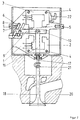
- a basic body is designated by 1 in FIG. It is in the 1 essentially only one drive detect. The second is behind.
- the visible drive has two electromagnets 2 and 3, whose yokes through Screws 4 are connected to the base body.
- the windings the electromagnets 2 and 3 are here for the sake of simplicity only shown schematically.
- the base body 1 is by means of Screws 5 attached to a box la, which in turn is attached to the cylinder block 20 by means of screws 5a.
- Anchor 10 is provided, which by a torsion spring z. B. one Torsion bar 6 is movably mounted.
- the torsion bar 6 and the corresponding torsion bar 7 for the armature of the other drive are shown in perspective for clarity. they are embedded in the body, clamped on one side in it (the torsion bar 6 at 8) and at the other end, e.g. B. means of a needle bearing.
- An anchor lever 9 is Connecting element between torsion bar 6 and anchor 10.
- a locking system is provided at the top right, which consists of a an axis 11 tiltable rocker 12, a locking magnet 13, one Spring 14 and a ball-bearing locking roller 15, which in the end positions of the anchor above or below the anchor snaps and holds it in the end positions. On the The locking roller will be discussed again later.
- In the basic body can be an invisible junction box for a plug be provided.
- the armature 10 is actuated via an actuating rod 16 and a Set screw 17 a valve 18 against the force of a spring 19.
- the length of the Actuating rod 16 can be changed. It serves the Setting the valve clearance at the dash-dotted line drawn position of the armature and then closed valve 18.
- Form the spring 19 and the bias of the torsion bar 6 the spring forces that without the excitation of an electromagnet Move the anchor to the intermediate position.
- Fig. 1 dimensions I1 for the valve length, I2 for the Valve block thickness, I3 for the distance of the axis of the torsion bar 6 from the valve block and I4 for the length of the actuating rod 16 registered.
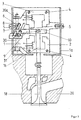
- Fig. 3 is a height adjustment of the drive together
- Spring bearing opposite the box la or the cylinder block shown, it consists of a screw 30 and one Belleville spring 31.
- the height adjustment option is used to adjust the valve clearance.
- screws 5 are loosened, turning nut 30a the screw 30 of the base body 1 more or less strong pressed against the plate springs 31 and thus the distance 13 (Fig 1) varies.
- valve clearance or Residual air gap setting only the upper magnet is adjustable. After correct valve lash setting related to one corresponding base air gap is the base body 1 by the Screws 5 screwed to the box.
- the magnet is adjusted against, for example Spring tension using an eccentric cam or over a screw mechanism.
- Advantageously Ensuring permanent adjustment of counter elements provided that secure the cam or screw elements.
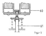
- Fig. 4 is a unit with two drives for two Valves 58a and 58b in a 90 ° (compared to FIGS. 1 to 3) rotated view shown.
- the basic body is 41 designated by the screws 45 (corresponding to 5) on box not shown can be attached.
- the basic body 41 carries two support plates 42 and 43, one each Torsion bar 46 and 47 is attached.
- the carrier plates can be fastened to the base body 41 by rivets or screws.
- the torsion bar can be fastened in the carrier plate by a positive connection is effected, e.g. can one square connected with the torsion bar or a toothing in shrink the carrier plate. Also one can Welding e.g. Laser welding can be used.
- the Connection from the torsion bars to the anchor levers 49 can in done in the same way.
- a metal bushing can be shrunk in the armature lever.
- the support bearings 50 for the free ones can also be seen here Ends of the torsion bars 46 and 47, in particular as needle bearings are trained.
- the valves 58 are also here Coupling spring coupled.
- a threaded nut 59 and one Spindle 60 are used for valve adjustment.
- actuating rods 60 two adjacent Actuators act on a valve stem 61 (Fig. 5).
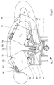
- FIG. 6 shows a cylinder 7 of an internal combustion engine, whose piston 72 is currently in the upper position.
- An inlet valve 73 and an outlet valve 74 are shown which are guided in the cylinder head 75.
- Valves 73 and 74 are driven by electromagnetic drives, which in Boxes 76 and 77 are housed. These are not through screws shown screwed onto the cylinder head 75.
- drives have two electromagnets and one mounted on a torsion bar via a connecting part Anchor on.
- the torsion bar is dimensioned such that the Anchor without driving an electromagnet in one Intermediate position.
- On the connecting part is one Actuator rod 78 and 79 attached via a Overtravel spring 80 or 81 with valve stem 73 or 74 connected is.
- the overtravel springs 80 and 81 provide Normally a rigid coupling of the valve stem to the Actuating rod 78 or 79. Only if the anchor one executes a larger stroke than the valve can take part in, the Spring action.
- the actuating rod including the overtravel spring protrude here from the bottom of the box.
- the parts are preferably not out of the box stick out.
- the connection between overtravel spring and Valve stem is detachable: e.g. have the overtravel springs 80 and 81 has a slot which, when installed in a groove of the Valve stem is inserted.
- the actuating rod 78 or 79 is preferably made of Made of aluminum. With 82 a spark plug is designated. This could also be housed in one of the boxes.
- a common cover 83 is for the two boxes 76 and 77 provided, in which the suction pipe 84 of the cylinder 71 is integrated is.
- the Electronics 85 of the drive unit e.g. B. also for several Drives attached. It is 86 through thermal insulation thermally insulated from the actual drive.
- Heatsink 87 of the electronics protrude into the intake manifold and become so well cooled by the relatively cool intake air.
- Cover 83 and electronics 84 and heat sink 87 can by a common screw 88 may be attached.
- one open - and lockable flap 79 to be integrated alternately a resonance suction tube - or To enable vibrating intake manifold operation.
- the torsion bar 90 is shown in box 91.
- an anchor 93 via a connecting part 92
- Electromagnet shown by two magnets, not shown can be moved up and down.
- the screws 94 shown with which the box 91 is attached to the cylinder head is.
- Actuating rod 95 (corresponds to 16 of FIG. 1) attached.
- Fig. 7 also shows a centering part 98 and in the cylinder block a housing centering 99. This ensures that the valve coupling is centered using the lift nut and snaps into the valve.
- a locking device here 100 is provided, which is rotatable about the point 101. she serves as an assembly aid.
- the seal 102 is between Box and lid recognizable.
- the electrical connection (contacting) of the solenoids with the electronics is in this arrangement the electronics very easy to do because all contacts with the PCB can be connected. They can also Stroke sensors housed in the electronics (on the board) become.
- the possible placement of the spark plugs in the Box means a "dry" housing, which means the insulation effort and the required ignition energy decreased.
Landscapes
- Physics & Mathematics (AREA)
- Electromagnetism (AREA)
- Engineering & Computer Science (AREA)
- Power Engineering (AREA)
- Mechanical Engineering (AREA)
- General Engineering & Computer Science (AREA)
- Valve Device For Special Equipments (AREA)
Abstract
Claims (33)
- Entraínement électromagnétique (2, 3, 10) comprenant deux électroaimants (2, 3), en particulier dont les surfaces polaires sont au moins partiellement tournées l'une vers l'autre, et comprenant un induit (10) en déplacement en va-et-vient entre ces surfaces polaires, ledit induit étant amené, lorsque les aimants (2,3) sont désexcités, par des forces élastiques (6, 7) jusque dans une position intermédiaire et y est maintenu, et l'induit est amené, lors de l'excitation de l'un des électroaimants (2, 3), jusque dans une position finale au voisinage des surfaces polaires de l'électroaimant correspondant (2, 3), ledit induit (10) étant monté au moyen d'un ressort de torsion (6) qui produit au moins partiellement les forces élastiques et agit sur une pièce (18) à entraíner, et dans lequel au moins un entraínement (2, 3, 10) conjointement avec son montage (6) sont regroupés sous la forme d'une unité structurelle et cette unité structurelle est fixée sur un composant (20) qui contient la pièce (18) à entraíner,
caractérisé en ce que plusieurs unités structurelles sont logées sur un élément de maintien ou de support (1a), en particulier dans un caisson largement fermé, et en ce que cet élément de maintien ou de support (1a) est fixé sur le composant (20). - Entraínement électromagnétique selon la revendication 1, caractérisé en ce que l'unité structurelle comprend deux entraínements (2, 3, 10) qui sont montés sur un corps de base commun (1).
- Entraínement électromagnétique selon la revendication 2, caractérisé en ce que l'unité structurelle comprend les deux entraínements (2, 3, 10) ensemble avec leurs montages (6, 7).
- Entraínement électromagnétique selon l'une des revendications précédentes, caractérisé en ce que les électroaimants (2, 3) sont fixés sur le corps de base (1) au moyen de vis (4) ou de rivets, et en ce que le réglage de l'entrefer résiduel a lieu par ajustement du système magnétique avant la fixation.
- Entraínement électromagnétique selon l'une des revendications précédentes, caractérisé en ce que les ressorts de torsion (6, 7) sont agencés l'un à côté de l'autre ou l'un au-dessous de l'autre approximativement à la même hauteur.
- Entraínement électromagnétique selon l'une des revendications précédentes, caractérisé en ce que les ressorts de torsion (6, 7) sont soutenus et montés dans le corps de base (1).
- Entraínement électromagnétique selon l'une des revendications précédentes, caractérisé en ce qu'il comprend un raccord (21) à enfichage, et en ce qu'il est réalisé sous forme d'une unité contrôlable (figure 2).
- Entraínement électromagnétique selon l'une des revendications précédentes, dans lequel les entraínements individuels servent chacun à entraíner une soupape d'un moteur à combustion interne, caractérisé en ce que l'on prévoit une vis de réglage (17) de jeu de soupape, afin de régler le jeu de la soupape.
- Entraínement électromagnétique selon l'une des revendications précédentes, dans lequel les entraínements individuels servent à chacun entraíner une soupape d'un moteur à combustion interne, caractérisé en ce que pour le réglage du jeu de soupape, chaque unité structurelle est réglable au moyen d'un dispositif de réglage (30, 30a).
- Entraínement électromagnétique selon la revendication 9, caractérisé en ce que pour le réglage du jeu de soupape ou pour le réglage de l'entrefer résiduel, l'aimant supérieur (3) est réglable.
- Entraínement électromagnétique selon la revendication 10, caractérisé en ce que l'aimant est monté de façon articulée sur un côté, avec faculté de rotation autour d'un axe, en particulier par l'intermédiaire d'un levier à titre d'élément de liaison.
- Entraínement électromagnétique selon la revendication 10, caractérisé en ce que l'aimant est capable de tourner autour de l'axe par l'intermédiaire d'un mécanisme à cames ou d'un mécanisme à vis.
- Entraínement électromagnétique selon l'une des revendications précédentes, caractérisé en ce que les enroulements électriques (20) des électroaimants sont en contact avec le corps de base (1).
- Entraínement électromagnétique selon l'une des revendications 1 à 7 et 13, caractérisé en ce que les deux entraínements entraínent une soupape (figure 5).
- Entraínement électromagnétique selon l'une des revendications précédentes, caractérisé en ce que le ressort de torsion (46, 47) est serré à une extrémité dans une plaque de support (42, 43), et est relié à l'extrémité libre à un levier d'induit (49) qui constitue une liaison vers l'induit (10), et en ce que la plaque de support (42, 43), le ressort de torsion (46, 47) et le levier d'induit (49) constituent une unité de montage, laquelle est fixée par coopération de forces ou par coopération de formes dans l'unité structurelle.
- Entraínement électromagnétique selon l'une des revendications précédentes, caractérisé en ce que l'extrémité libre du ressort de torsion (46,47) comporte un montage de soutien (50).
- Entraínement électromagnétique selon la revendication 16, caractérisé en ce que le montage de soutien est un palier à aiguilles.
- Entraínement électromagnétique selon l'une des revendications 15 à 17, caractérisé en ce que le ressort de torsion (46, 47) est soudé avec la plaque de support (42, 43) et avec le levier d'induit.
- Entraínement électromagnétique selon l'une des revendications 15 à 17, caractérisé en ce que le ressort de torsion est relié à la plaque de support et au levier d'induit au moyen d'un profil correspondant via des liaisons à coopération de formes ou à coopération de forces.
- Entraínement électromagnétique selon l'une des revendications 8 à 19, caractérisé en ce que le les réalisations et des matériaux du bloc de soupape, de la soupape (18) et de l'organe d'actionnement (16) sont ainsi choisis que dans la position de fermeture de la soupape (18) il se produit une influence la plus faible possible sur la levée de l'induit, ou sur le jeu de soupape, à des températures moteur différentes.
- Entraínement électromagnétique selon l'une des revendications 7 à 20, caractérisé en ce que les forces élastiques sont produites par une barre de torsion (6) et par un ressort de compression (19) au niveau de la soupape (figure 1).
- Entraínement électromagnétique selon l'une des revendications 7 à 21, caractérisé en ce que deux entraínements agissent sur une soupape.
- Entraínement électromagnétique selon l'une des revendications 8 à 22, caractérisé en ce que l'élément de maintien ou de support, en particulier le caisson (la ; 6,7), est posé avec son fond sur la tête de cylindre (20; 75) et est relié à celle-ci.
- Entraínement électromagnetiqué selon la revendication 23, caractérisé en ce que le caisson (6, 7) comprend un couvercle (73), et en ce que le tube d'aspiration (84) d'un cylindre (71) du moteur à combustion interne est intégré dans ce couvercle.
- Entraínement électromagnétique selon l'une ou l'autre des revendications au 23 et 24, caractérisé en ce que le système électronique (85) de l'unité d'entraínement est agencé au moins partiellement dans le tube d'aspiration (84).
- Entraínement électromagnétique selon l'une ou l'autre des revendications 24 et 25, caractérisé en ce que des corps de refroidissement (85) du système électronique (85) de l'unité d'entraínement pénètrent dans le tube de d'aspiration (84).
- Entraínement électromagnétique selon l'une des revendications 23 à 26, caractérisé en ce que le système électronique (85) est thermiquement isolé par rapport aux entraínements (isolation 86).
- Entraínement électromagnétique selon l'une des revendications 23 à 27, caractérisé en ce qu'au moins une bougie d'allumage est logée dans le caisson.
- Entraínement électromagnétique selon l'une des revendications 23 à 28, caractérisé en ce que les organes d'actionnement (16, 78, 79) sont en aluminium.
- Entraínement électromagnétique selon l'une des revendications 23 à 29, caractérisé en ce que la soupape comprend, à titre d'aide au montage, un dispositif à enclenchement (100).
- Entraínement électromagnétique selon l'une des revendications 23 à 30, caractérisé en ce que le caisson (76, 77) comprend une partie de centrage (98), et en ce qu'il est prévu dans le bloc de cylindre un centrage (99) pour le caisson (76, 77).
- Entraínement électromagnétique selon l'une des revendications 23 à 31, caractérisé en ce qu'un tube d'aspiration commandé (89) avec unité de commande est intégré dans l'unité de couvercle (83).
- Entraínement électromagnétique selon l'une des revendications précédentes, caractérisé en ce que l'unité de couvercle (83) est reliée avec des vis (83) avec le caisson étanché.
Applications Claiming Priority (7)
| Application Number | Priority Date | Filing Date | Title |
|---|---|---|---|
| DE19712056A DE19712056A1 (de) | 1997-03-24 | 1997-03-24 | Elektromagnetischer Antrieb E8 |
| DE19712055 | 1997-03-24 | ||
| DE19712056 | 1997-03-24 | ||
| DE19712055A DE19712055A1 (de) | 1997-03-24 | 1997-03-24 | Elektronisch angetriebenes Ventil für einen Verbrennungsmotor E 11 |
| DE19741571A DE19741571A1 (de) | 1997-09-20 | 1997-09-20 | Elektromagnetische Antriebseinheit |
| DE19741571 | 1997-09-20 | ||
| PCT/EP1998/001709 WO1998042957A1 (fr) | 1997-03-24 | 1998-03-24 | Dispositif d'entrainement electromagnetique |
Publications (2)
| Publication Number | Publication Date |
|---|---|
| EP0970295A1 EP0970295A1 (fr) | 2000-01-12 |
| EP0970295B1 true EP0970295B1 (fr) | 2001-06-20 |
Family
ID=27217240
Family Applications (1)
| Application Number | Title | Priority Date | Filing Date |
|---|---|---|---|
| EP98917064A Expired - Lifetime EP0970295B1 (fr) | 1997-03-24 | 1998-03-24 | Dispositif d'entrainement electromagnetique |
Country Status (4)
| Country | Link |
|---|---|
| US (1) | US6262498B1 (fr) |
| EP (1) | EP0970295B1 (fr) |
| DE (1) | DE59800892D1 (fr) |
| WO (1) | WO1998042957A1 (fr) |
Families Citing this family (30)
| Publication number | Priority date | Publication date | Assignee | Title |
|---|---|---|---|---|
| DE19837837C1 (de) * | 1998-08-20 | 2000-01-05 | Daimler Chrysler Ag | Vorrichtung zum Betätigen eines Gaswechselventils |
| WO2000029723A1 (fr) * | 1998-11-16 | 2000-05-25 | Heinz Leiber | Systeme d'entrainement electromagnetique |
| IT1310488B1 (it) | 1999-09-23 | 2002-02-18 | Magneti Marelli Spa | Attuatore elettromagnetico per il comando delle valvole di un motore ascoppio. |
| WO2001025599A1 (fr) | 1999-10-07 | 2001-04-12 | Heinz Leiber | Systeme electromagnetique de commande a soupapes |
| DE19948494A1 (de) * | 1999-10-07 | 2001-04-12 | Heinz Leiber | Elektromagnetischer Aktuator |
| DE19948205A1 (de) * | 1999-10-07 | 2001-04-12 | Heinz Leiber | Elektromagnetische Ventilsteueranordnung |
| ITBO20000127A1 (it) * | 2000-03-09 | 2001-09-09 | Magneti Marelli Spa | Attuatore elettromagnetico per l' azionamento delle valvole di un motore a scoppio con recupero dei giochi meccanici . |
| ITBO20000366A1 (it) * | 2000-06-23 | 2001-12-23 | Magneti Marelli Spa | Attuatore elettromagnetico per l'azionamento delle valvole di un motore a scoppio . |
| DE10035759A1 (de) * | 2000-07-22 | 2002-01-31 | Daimler Chrysler Ag | Elektromagnetischer Aktuator zur Betätigung eines Gaswechselventils einer Brennkraftmaschine |
| KR100401645B1 (ko) * | 2001-08-21 | 2003-10-17 | 현대자동차주식회사 | 전자 기계식 밸브 트레인 |
| FR2834119B1 (fr) | 2001-08-30 | 2004-05-21 | Moving Magnet Tech Mmt | Actionneur electromagnetique a deux positions stables de fin de course, notamment pour la commande de vannes de conduits d'admission d'air pour moteurs a combustion interne |
| US6681731B2 (en) * | 2001-12-11 | 2004-01-27 | Visteon Global Technologies, Inc. | Variable valve mechanism for an engine |
| DE10226524A1 (de) * | 2002-06-14 | 2003-12-24 | Daimler Chrysler Ag | Elektromagnetischer Aktuator |
| DE10231374A1 (de) * | 2002-07-11 | 2004-01-22 | Daimlerchrysler Ag | Aktuator |
| US7070162B2 (en) * | 2003-07-18 | 2006-07-04 | South Bend Controls, Inc. | Valve actuating apparatus |
| US7152558B2 (en) * | 2003-10-14 | 2006-12-26 | Visteon Global Technologies, Inc. | Electromechanical valve actuator assembly |
| US7255073B2 (en) * | 2003-10-14 | 2007-08-14 | Visteon Global Technologies, Inc. | Electromechanical valve actuator beginning of stroke damper |
| US7089894B2 (en) | 2003-10-14 | 2006-08-15 | Visteon Global Technologies, Inc. | Electromechanical valve actuator assembly |
| US20050076866A1 (en) * | 2003-10-14 | 2005-04-14 | Hopper Mark L. | Electromechanical valve actuator |
| DE102004050013B4 (de) * | 2003-10-14 | 2009-03-19 | Visteon Global Technologies Inc., Van Buren | Elektromechanischer Ventilauslöser |
| US7314026B2 (en) * | 2004-01-21 | 2008-01-01 | Ford Global Technologies, Llc | Electronic valve actuator having hydraulic displacement amplifier |
| US6997433B2 (en) * | 2004-01-21 | 2006-02-14 | Ford Global Technologies, Llc | Electronic valve actuator having vibration cancellation |
| JP2006022776A (ja) * | 2004-07-09 | 2006-01-26 | Toyota Motor Corp | 電磁駆動弁 |
| JP2006057521A (ja) * | 2004-08-19 | 2006-03-02 | Toyota Motor Corp | 電磁駆動弁 |
| JP4179250B2 (ja) * | 2004-09-03 | 2008-11-12 | トヨタ自動車株式会社 | 電磁駆動弁の制御装置 |
| US7305942B2 (en) * | 2005-02-23 | 2007-12-11 | Visteon Global Technologies, Inc. | Electromechanical valve actuator |
| US7374147B2 (en) * | 2005-10-14 | 2008-05-20 | Et Us Holdings Llc | Valve assembly with overstroke device and associated method |
| US20100314568A1 (en) * | 2009-06-15 | 2010-12-16 | South Bend Controls, Inc. | Solenoid coil |
| US8957831B1 (en) | 2010-03-30 | 2015-02-17 | The Boeing Company | Artificial magnetic conductors |
| CN110925475B (zh) * | 2019-12-04 | 2021-08-17 | 济南市大秦机电设备有限公司 | 一种导向无压差电磁控制阀 |
Family Cites Families (29)
| Publication number | Priority date | Publication date | Assignee | Title |
|---|---|---|---|---|
| DE641845C (de) | 1935-09-21 | 1937-02-15 | Phaenomen Werke Gustav Hiller | Steuerung fuer Brennkraftmaschinen |
| DE2038675A1 (de) | 1970-08-04 | 1972-02-10 | Kayser Uwe Dipl Ing | Selbsttaetiger Ventilspielausgleich durch elektrisch beheizten Dehnungskoerper |
| DE2317246A1 (de) | 1973-04-06 | 1974-10-17 | Audi Nsu Auto Union Ag | Ventildeckel fuer brennkraftmaschinen |
| DE2334211A1 (de) * | 1973-07-05 | 1974-11-21 | Schneider Co Optische Werke | Stellmotor |
| GB1471537A (en) | 1974-12-06 | 1977-04-27 | Venard R | Engine valve control |
| DE3024109A1 (de) | 1980-06-27 | 1982-01-21 | Pischinger, Franz, Prof. Dipl.-Ing. Dr.Techn., 5100 Aachen | Elektromagnetisch arbeitende stelleinrichtung |
| DE3031354A1 (de) | 1980-08-20 | 1982-04-08 | Robert Bosch Gmbh, 7000 Stuttgart | Elektromagnetische anordnung |
| GB2088137A (en) | 1980-11-21 | 1982-06-03 | Veisz Gyoergy | Magnetomechanical converter |
| DE3208348A1 (de) | 1981-05-20 | 1982-12-09 | Robert Bosch Gmbh, 7000 Stuttgart | Elektromagnet-aggregat |
| DE8310859U1 (de) | 1983-04-13 | 1985-01-24 | Grote & Hartmann Gmbh & Co Kg, 5600 Wuppertal | Elektrischer Stecker |
| US4717900A (en) | 1984-03-30 | 1988-01-05 | Aisin Seiki Kabushiki Kaisha | Low profile electromagnetic linear motion device |
| DE3616540A1 (de) | 1986-05-16 | 1987-11-19 | Porsche Ag | Vorrichtung zum betaetigen eines gaswechsel-tellerventils einer hubkolben-brennkraftmaschine |
| DE3802836A1 (de) | 1988-02-01 | 1989-08-03 | Joern Martens | Verbrennungskraftmaschine |
| JP2759461B2 (ja) | 1988-10-12 | 1998-05-28 | ヤマハ発動機株式会社 | エンジンの吸気装置 |
| JP2647951B2 (ja) | 1989-02-28 | 1997-08-27 | ヤマハ発動機株式会社 | 車両用エンジンのブローバイガス回収装置 |
| JP2709128B2 (ja) | 1989-03-03 | 1998-02-04 | ヤマハ発動機株式会社 | 車両用エンジンの吸気装置 |
| DE3920976A1 (de) * | 1989-06-27 | 1991-01-03 | Fev Motorentech Gmbh & Co Kg | Elektromagnetisch arbeitende stelleinrichtung |
| DE3920931A1 (de) * | 1989-06-27 | 1991-01-03 | Fev Motorentech Gmbh & Co Kg | Elektromagnetisch arbeitende stelleinrichtung |
| US5161494A (en) | 1992-01-15 | 1992-11-10 | Brown Jr John N | Electromagnetic valve actuator |
| US5224683A (en) * | 1992-03-10 | 1993-07-06 | North American Philips Corporation | Hydraulic actuator with hydraulic springs |
| US5548263A (en) * | 1992-10-05 | 1996-08-20 | Aura Systems, Inc. | Electromagnetically actuated valve |
| US5720468A (en) * | 1992-10-05 | 1998-02-24 | Aura Systems, Inc. | Staggered electromagnetically actuated valve design |
| DE19511880A1 (de) | 1994-04-08 | 1995-10-12 | Audi Ag | Vorrichtung zum Betätigen von Gaswechsel-Ventilen |
| DE4430324C1 (de) | 1994-08-26 | 1996-10-10 | Vdo Schindling | Saugrohr |
| JP3186462B2 (ja) | 1994-09-22 | 2001-07-11 | トヨタ自動車株式会社 | 内燃機関の電磁式弁駆動装置 |
| DE69517335T2 (de) * | 1994-11-09 | 2001-01-04 | Aura Systems Inc., El Segundo | Elektromagnetisch gelenktes ventil mit gelenkter armatur |
| DE19506566A1 (de) | 1995-02-24 | 1996-08-29 | Bayerische Motoren Werke Ag | Elektromagnetische Hubventil-Betätigungsvorrichtung |
| DE19628860B4 (de) * | 1996-07-17 | 2008-07-31 | Bayerische Motoren Werke Aktiengesellschaft | Elektromagnetische Betätigungsvorrichtung für ein Brennkraftmaschinen-Hubventil |
| JP3605478B2 (ja) * | 1996-08-21 | 2004-12-22 | 本田技研工業株式会社 | 内燃機関の動弁装置 |
-
1998
- 1998-03-24 EP EP98917064A patent/EP0970295B1/fr not_active Expired - Lifetime
- 1998-03-24 US US09/381,781 patent/US6262498B1/en not_active Expired - Fee Related
- 1998-03-24 DE DE59800892T patent/DE59800892D1/de not_active Expired - Lifetime
- 1998-03-24 WO PCT/EP1998/001709 patent/WO1998042957A1/fr active IP Right Grant
Also Published As
| Publication number | Publication date |
|---|---|
| EP0970295A1 (fr) | 2000-01-12 |
| DE59800892D1 (de) | 2001-07-26 |
| WO1998042957A1 (fr) | 1998-10-01 |
| US6262498B1 (en) | 2001-07-17 |
Similar Documents
| Publication | Publication Date | Title |
|---|---|---|
| EP0970295B1 (fr) | Dispositif d'entrainement electromagnetique | |
| EP0405187B1 (fr) | Dispositif électromagnétique de positionnement | |
| DE29712502U1 (de) | Elektromagnetischer Aktuator mit Gehäuse | |
| EP1131540B1 (fr) | Systeme d'entrainement electromagnetique | |
| EP0796981B1 (fr) | Dispositif de commande électromagnétique pour soupape de moteur à combustion interne | |
| EP0356713A1 (fr) | Dispositif de positionnement actionné électromagnétiquement | |
| DE102009006355A1 (de) | Proportionalmagnet für ein hydraulisches Wegeventil und Verfahren zu dessen Herstellung | |
| WO2000070196A1 (fr) | Mecanisme de commande multiple electromagnetique | |
| DE60200819T2 (de) | Ventilbetätigungsvorrichtung einer Brennkraftmaschine | |
| DE102017129420A1 (de) | Variabler Ventiltrieb eines Verbrennungskolbenmotors | |
| WO2008131833A1 (fr) | Dispositif magnétique commutable | |
| DE20109597U1 (de) | Vorrichtung zur Betätigung eines Gaswechselventils einer Brennkraftmaschine | |
| EP1069285B1 (fr) | Dispositif électromagnétique pour actionner une soupape de gaz avec des ressorts concentriquement emboítés | |
| DE102011012020B4 (de) | Nockenwelle mit Nockenwellenversteller | |
| EP4058704B1 (fr) | Actionneur de soupape électromagnétique pour soupape à actionnement électromagnétique sans arrêt, soupape et moteur à combustion interne à piston alternatif avec soupape | |
| DE19607019A1 (de) | Vorrichtung zur elektromagnetischen Betätigung eines Gaswechselventiles für Verbrennungsmotoren | |
| DE3928066A1 (de) | Vorrichtung zur elektromagnetischen steuerung eines gaswechsel-ventils einer hubkolben-brennkraftmaschine | |
| DE19955067A1 (de) | Elektromagnetischer Aktuator | |
| WO2001054146A1 (fr) | Electroaimant | |
| DE29700096U1 (de) | Elektromagnetischer Aktuator zur Betätigung eines Gaswechselventils mit Dämpfungsmitteln zur Verminderung der Körperschallübertragung | |
| DE10055948A1 (de) | Drehmomentfreie Schraubenfederanordnung | |
| DE10003930C1 (de) | Vorrichtung zur Betätigung eines Gaswechselventils | |
| DE19712056A1 (de) | Elektromagnetischer Antrieb E8 | |
| DE19820829C1 (de) | Elektromagnetische Vorrichtung zur Betätigung eines Gaswechselventils einer Brennkraftmaschine | |
| DE102004050013B4 (de) | Elektromechanischer Ventilauslöser |
Legal Events
| Date | Code | Title | Description |
|---|---|---|---|
| PUAI | Public reference made under article 153(3) epc to a published international application that has entered the european phase |
Free format text: ORIGINAL CODE: 0009012 |
|
| 17P | Request for examination filed |
Effective date: 19990831 |
|
| AK | Designated contracting states |
Kind code of ref document: A1 Designated state(s): DE FR GB IT SE |
|
| GRAG | Despatch of communication of intention to grant |
Free format text: ORIGINAL CODE: EPIDOS AGRA |
|
| 17Q | First examination report despatched |
Effective date: 20000530 |
|
| GRAG | Despatch of communication of intention to grant |
Free format text: ORIGINAL CODE: EPIDOS AGRA |
|
| GRAH | Despatch of communication of intention to grant a patent |
Free format text: ORIGINAL CODE: EPIDOS IGRA |
|
| GRAH | Despatch of communication of intention to grant a patent |
Free format text: ORIGINAL CODE: EPIDOS IGRA |
|
| ITF | It: translation for a ep patent filed | ||
| GRAA | (expected) grant |
Free format text: ORIGINAL CODE: 0009210 |
|
| AK | Designated contracting states |
Kind code of ref document: B1 Designated state(s): DE FR GB IT SE |
|
| GBT | Gb: translation of ep patent filed (gb section 77(6)(a)/1977) |
Effective date: 20010621 |
|
| REF | Corresponds to: |
Ref document number: 59800892 Country of ref document: DE Date of ref document: 20010726 |
|
| PG25 | Lapsed in a contracting state [announced via postgrant information from national office to epo] |
Ref country code: SE Free format text: LAPSE BECAUSE OF FAILURE TO SUBMIT A TRANSLATION OF THE DESCRIPTION OR TO PAY THE FEE WITHIN THE PRESCRIBED TIME-LIMIT Effective date: 20010920 |
|
| ET | Fr: translation filed | ||
| REG | Reference to a national code |
Ref country code: GB Ref legal event code: IF02 |
|
| PLBE | No opposition filed within time limit |
Free format text: ORIGINAL CODE: 0009261 |
|
| STAA | Information on the status of an ep patent application or granted ep patent |
Free format text: STATUS: NO OPPOSITION FILED WITHIN TIME LIMIT |
|
| 26N | No opposition filed | ||
| PGFP | Annual fee paid to national office [announced via postgrant information from national office to epo] |
Ref country code: GB Payment date: 20030402 Year of fee payment: 6 |
|
| PG25 | Lapsed in a contracting state [announced via postgrant information from national office to epo] |
Ref country code: GB Free format text: LAPSE BECAUSE OF NON-PAYMENT OF DUE FEES Effective date: 20040324 |
|
| PGFP | Annual fee paid to national office [announced via postgrant information from national office to epo] |
Ref country code: FR Payment date: 20040421 Year of fee payment: 7 |
|
| GBPC | Gb: european patent ceased through non-payment of renewal fee |
Effective date: 20040324 |
|
| PG25 | Lapsed in a contracting state [announced via postgrant information from national office to epo] |
Ref country code: IT Free format text: LAPSE BECAUSE OF NON-PAYMENT OF DUE FEES;WARNING: LAPSES OF ITALIAN PATENTS WITH EFFECTIVE DATE BEFORE 2007 MAY HAVE OCCURRED AT ANY TIME BEFORE 2007. THE CORRECT EFFECTIVE DATE MAY BE DIFFERENT FROM THE ONE RECORDED. Effective date: 20050324 |
|
| PG25 | Lapsed in a contracting state [announced via postgrant information from national office to epo] |
Ref country code: FR Free format text: LAPSE BECAUSE OF NON-PAYMENT OF DUE FEES Effective date: 20051130 |
|
| REG | Reference to a national code |
Ref country code: FR Ref legal event code: ST Effective date: 20051130 |
|
| PGFP | Annual fee paid to national office [announced via postgrant information from national office to epo] |
Ref country code: DE Payment date: 20140325 Year of fee payment: 17 |
|
| REG | Reference to a national code |
Ref country code: DE Ref legal event code: R119 Ref document number: 59800892 Country of ref document: DE |
|
| PG25 | Lapsed in a contracting state [announced via postgrant information from national office to epo] |
Ref country code: DE Free format text: LAPSE BECAUSE OF NON-PAYMENT OF DUE FEES Effective date: 20151001 |