EP0969200B1 - Im tank eingebauter brennstofffilter mit verbessertem wiederstand gegen elektrische aufladung - Google Patents
Im tank eingebauter brennstofffilter mit verbessertem wiederstand gegen elektrische aufladung Download PDFInfo
- Publication number
- EP0969200B1 EP0969200B1 EP98907193A EP98907193A EP0969200B1 EP 0969200 B1 EP0969200 B1 EP 0969200B1 EP 98907193 A EP98907193 A EP 98907193A EP 98907193 A EP98907193 A EP 98907193A EP 0969200 B1 EP0969200 B1 EP 0969200B1
- Authority
- EP
- European Patent Office
- Prior art keywords
- filter
- fuel
- case
- tank
- filter case
- Prior art date
- Legal status (The legal status is an assumption and is not a legal conclusion. Google has not performed a legal analysis and makes no representation as to the accuracy of the status listed.)
- Expired - Lifetime
Links
- 239000000446 fuel Substances 0.000 title claims description 213
- 230000002093 peripheral effect Effects 0.000 claims description 47
- 239000011347 resin Substances 0.000 claims description 34
- 229920005989 resin Polymers 0.000 claims description 34
- 239000012811 non-conductive material Substances 0.000 claims description 17
- 239000000463 material Substances 0.000 claims description 12
- 239000002828 fuel tank Substances 0.000 claims description 9
- 230000008878 coupling Effects 0.000 claims 4
- 238000010168 coupling process Methods 0.000 claims 4
- 238000005859 coupling reaction Methods 0.000 claims 4
- 239000002184 metal Substances 0.000 description 9
- 238000000034 method Methods 0.000 description 9
- 238000007599 discharging Methods 0.000 description 7
- 238000013461 design Methods 0.000 description 6
- 239000004020 conductor Substances 0.000 description 5
- 230000003068 static effect Effects 0.000 description 5
- 230000003247 decreasing effect Effects 0.000 description 4
- 238000001914 filtration Methods 0.000 description 3
- 238000010276 construction Methods 0.000 description 2
- 230000005611 electricity Effects 0.000 description 2
- 238000004519 manufacturing process Methods 0.000 description 2
- 238000005452 bending Methods 0.000 description 1
- 238000012790 confirmation Methods 0.000 description 1
- 230000006866 deterioration Effects 0.000 description 1
- 230000002542 deteriorative effect Effects 0.000 description 1
- 230000000694 effects Effects 0.000 description 1
- 238000002474 experimental method Methods 0.000 description 1
- 239000007788 liquid Substances 0.000 description 1
- 238000012423 maintenance Methods 0.000 description 1
- 239000002245 particle Substances 0.000 description 1
- 238000005192 partition Methods 0.000 description 1
- 230000001603 reducing effect Effects 0.000 description 1
- 125000006850 spacer group Chemical group 0.000 description 1
- 238000012795 verification Methods 0.000 description 1
Images


Classifications
-
- B—PERFORMING OPERATIONS; TRANSPORTING
- B01—PHYSICAL OR CHEMICAL PROCESSES OR APPARATUS IN GENERAL
- B01D—SEPARATION
- B01D35/00—Filtering devices having features not specifically covered by groups B01D24/00 - B01D33/00, or for applications not specifically covered by groups B01D24/00 - B01D33/00; Auxiliary devices for filtration; Filter housing constructions
- B01D35/26—Filters with built-in pumps filters provided with a pump mounted in or on the casing
-
- B—PERFORMING OPERATIONS; TRANSPORTING
- B01—PHYSICAL OR CHEMICAL PROCESSES OR APPARATUS IN GENERAL
- B01D—SEPARATION
- B01D29/00—Filters with filtering elements stationary during filtration, e.g. pressure or suction filters, not covered by groups B01D24/00 - B01D27/00; Filtering elements therefor
- B01D29/01—Filters with filtering elements stationary during filtration, e.g. pressure or suction filters, not covered by groups B01D24/00 - B01D27/00; Filtering elements therefor with flat filtering elements
- B01D29/05—Filters with filtering elements stationary during filtration, e.g. pressure or suction filters, not covered by groups B01D24/00 - B01D27/00; Filtering elements therefor with flat filtering elements supported
- B01D29/07—Filters with filtering elements stationary during filtration, e.g. pressure or suction filters, not covered by groups B01D24/00 - B01D27/00; Filtering elements therefor with flat filtering elements supported with corrugated, folded or wound filtering sheets
- B01D29/071—Filters with filtering elements stationary during filtration, e.g. pressure or suction filters, not covered by groups B01D24/00 - B01D27/00; Filtering elements therefor with flat filtering elements supported with corrugated, folded or wound filtering sheets with curved filtering elements
-
- B—PERFORMING OPERATIONS; TRANSPORTING
- B01—PHYSICAL OR CHEMICAL PROCESSES OR APPARATUS IN GENERAL
- B01D—SEPARATION
- B01D35/00—Filtering devices having features not specifically covered by groups B01D24/00 - B01D33/00, or for applications not specifically covered by groups B01D24/00 - B01D33/00; Auxiliary devices for filtration; Filter housing constructions
- B01D35/02—Filters adapted for location in special places, e.g. pipe-lines, pumps, stop-cocks
- B01D35/027—Filters adapted for location in special places, e.g. pipe-lines, pumps, stop-cocks rigidly mounted in or on tanks or reservoirs
-
- F—MECHANICAL ENGINEERING; LIGHTING; HEATING; WEAPONS; BLASTING
- F02—COMBUSTION ENGINES; HOT-GAS OR COMBUSTION-PRODUCT ENGINE PLANTS
- F02M—SUPPLYING COMBUSTION ENGINES IN GENERAL WITH COMBUSTIBLE MIXTURES OR CONSTITUENTS THEREOF
- F02M37/00—Apparatus or systems for feeding liquid fuel from storage containers to carburettors or fuel-injection apparatus; Arrangements for purifying liquid fuel specially adapted for, or arranged on, internal-combustion engines
- F02M37/04—Feeding by means of driven pumps
- F02M37/08—Feeding by means of driven pumps electrically driven
- F02M37/10—Feeding by means of driven pumps electrically driven submerged in fuel, e.g. in reservoir
-
- F—MECHANICAL ENGINEERING; LIGHTING; HEATING; WEAPONS; BLASTING
- F02—COMBUSTION ENGINES; HOT-GAS OR COMBUSTION-PRODUCT ENGINE PLANTS
- F02M—SUPPLYING COMBUSTION ENGINES IN GENERAL WITH COMBUSTIBLE MIXTURES OR CONSTITUENTS THEREOF
- F02M37/00—Apparatus or systems for feeding liquid fuel from storage containers to carburettors or fuel-injection apparatus; Arrangements for purifying liquid fuel specially adapted for, or arranged on, internal-combustion engines
- F02M37/22—Arrangements for purifying liquid fuel specially adapted for, or arranged on, internal-combustion engines, e.g. arrangements in the feeding system
- F02M37/32—Arrangements for purifying liquid fuel specially adapted for, or arranged on, internal-combustion engines, e.g. arrangements in the feeding system characterised by filters or filter arrangements
- F02M37/34—Arrangements for purifying liquid fuel specially adapted for, or arranged on, internal-combustion engines, e.g. arrangements in the feeding system characterised by filters or filter arrangements by the filter structure, e.g. honeycomb, mesh or fibrous
-
- F—MECHANICAL ENGINEERING; LIGHTING; HEATING; WEAPONS; BLASTING
- F02—COMBUSTION ENGINES; HOT-GAS OR COMBUSTION-PRODUCT ENGINE PLANTS
- F02M—SUPPLYING COMBUSTION ENGINES IN GENERAL WITH COMBUSTIBLE MIXTURES OR CONSTITUENTS THEREOF
- F02M37/00—Apparatus or systems for feeding liquid fuel from storage containers to carburettors or fuel-injection apparatus; Arrangements for purifying liquid fuel specially adapted for, or arranged on, internal-combustion engines
- F02M37/22—Arrangements for purifying liquid fuel specially adapted for, or arranged on, internal-combustion engines, e.g. arrangements in the feeding system
- F02M37/32—Arrangements for purifying liquid fuel specially adapted for, or arranged on, internal-combustion engines, e.g. arrangements in the feeding system characterised by filters or filter arrangements
- F02M37/44—Filters structurally associated with pumps
-
- F—MECHANICAL ENGINEERING; LIGHTING; HEATING; WEAPONS; BLASTING
- F02—COMBUSTION ENGINES; HOT-GAS OR COMBUSTION-PRODUCT ENGINE PLANTS
- F02M—SUPPLYING COMBUSTION ENGINES IN GENERAL WITH COMBUSTIBLE MIXTURES OR CONSTITUENTS THEREOF
- F02M37/00—Apparatus or systems for feeding liquid fuel from storage containers to carburettors or fuel-injection apparatus; Arrangements for purifying liquid fuel specially adapted for, or arranged on, internal-combustion engines
- F02M37/22—Arrangements for purifying liquid fuel specially adapted for, or arranged on, internal-combustion engines, e.g. arrangements in the feeding system
- F02M37/32—Arrangements for purifying liquid fuel specially adapted for, or arranged on, internal-combustion engines, e.g. arrangements in the feeding system characterised by filters or filter arrangements
- F02M37/46—Filters structurally associated with pressure regulators
-
- F—MECHANICAL ENGINEERING; LIGHTING; HEATING; WEAPONS; BLASTING
- F02—COMBUSTION ENGINES; HOT-GAS OR COMBUSTION-PRODUCT ENGINE PLANTS
- F02M—SUPPLYING COMBUSTION ENGINES IN GENERAL WITH COMBUSTIBLE MIXTURES OR CONSTITUENTS THEREOF
- F02M37/00—Apparatus or systems for feeding liquid fuel from storage containers to carburettors or fuel-injection apparatus; Arrangements for purifying liquid fuel specially adapted for, or arranged on, internal-combustion engines
- F02M37/22—Arrangements for purifying liquid fuel specially adapted for, or arranged on, internal-combustion engines, e.g. arrangements in the feeding system
- F02M37/32—Arrangements for purifying liquid fuel specially adapted for, or arranged on, internal-combustion engines, e.g. arrangements in the feeding system characterised by filters or filter arrangements
- F02M37/50—Filters arranged in or on fuel tanks
-
- B—PERFORMING OPERATIONS; TRANSPORTING
- B01—PHYSICAL OR CHEMICAL PROCESSES OR APPARATUS IN GENERAL
- B01D—SEPARATION
- B01D2201/00—Details relating to filtering apparatus
- B01D2201/50—Means for dissipating electrostatic charges
Definitions
- the present invention relates to a fuel filter for filtering foreign matter from fuel drawn by a fuel pump from a fuel tank.
- the present invention relates to an in-tank fuel filter system that is used in a fuel tank, and more particularly, to an in-tank fuel filter system that has improved resistance to static electricity.
- a fuel pump is simply referred to as a pump, a fuel tank as a tank, and a filter used in the tank as an in-tank filter system.
- a filter is constructed in modules by assembling a generally cylindrical filter unit around a generally cylindrical pump.
- the filter module is disposed for use within a tank.
- the known in-tank filter module system is very effective for simplifying the process of mounting the pump and the filter unit in the tank.
- no particular consideration was given to the fact that the filter and the fuel become electrically charged.
- the fuel piping is normally attached to a vehicle body by an insulating elastic element, such as a rubber bushing, in order to protect the fuel piping from vibrations. Therefore, the fuel piping is electrically insulated from the vehicle body. Electrification of the fuel piping causes an electric discharge between the fuel piping and the metal vehicle parts adjacent to the fuel piping. The electric discharge may possibly damage the fuel pipe wall. Some instances of serious fuel pipe wall damage have actually occurred as a result of repeated static electric discharges.
- the life of the filter element may be shortened and/or spark discharges may be generated.
- the filter cover forming the filter surface is made of a nonconductive material such as a resin, the possibility of generating a spark discharge is reduced. However, the resin deteriorates as a result of this electrification and thus, the filter life is shortened. If the filter cover is made of a conductive material such as a metal, the life is not shortened significantly, but spark discharges tend to be readily generated. Thus, the charge generated by the filtering process causes serious problems for the filter and the fuel piping as well.
- the fuel is filtered by flowing axially, instead of radially, with respect to the cylindrical filter element.
- the amount of static charge that is generated in the fuel or on the filter element, when the fuel passes through the filter element to filter foreign matter from the fuel is not only influenced by the total amount of fuel passing through the filter, but also by the flow rate and the time required for the fuel to pass through the filter element. The faster the flow rate, the more readily the filter element is electrically charged. Further, the longer the time required for the fuel to pass through the filter element, the more readily the filter element is electrically charged.
- a cylindrical filter element is used to filter the fuel
- the fuel flow rate, the contact distance of the fuel with the filter element and the time required for the fuel to pass through the filter element are increased as compared with a filter element in which the fuel flows radially through the filter element.
- the fuel flow rate, the contact distance of the fuel with the filter element and the required time for the fuel to pass through the filter element are reduced.
- the amount of electric charge generated on the filter element, through which the fuel flows radially is much less than an axial-flow type filter element.
- the most common method taken to prevent electrification of the filter is to discharge the electric charge. It is generally believed that the electric charge cannot be discharged if the filter cover forming the filter surface is made of resin. Therefore, in the commonly used designs, the filter cover is made of metal and a ground wire is connected between the metal cover and the vehicle body or the like, so that electric charge built up on the filter cover is discharged to the vehicle body or the like.
- the filter is made of metal, the manufacturing cost is increased, and the design options for the cover configuration are limited.
- a method in which the filter cover is made of conductive resin was proposed and disclosed in International Patent Publication No. WO 92/04097 (corresponding to Japanese Laid-Open Patent Publication No. 6-500373). This publication discloses a technique in which a filter cover is made of a conductive resin and a ground wire is connected between the cover and the vehicle body, so that electric charge built up on the filter cover is discharged.
- the filter cover is made of a conductive material, such as a metal or a conductive resin, and is connected to a ground wire to discharge the electric charge built-up on the filter.
- the electric charge on the filter can be discharged, but the electric charge in the fuel cannot be discharged.
- no measures are taken to prevent electrification of the fuel piping.
- the fuel piping which is normally connected to a vehicle body or the like by an insulating member such as a rubber bushing, becomes electrically charged, spark discharges will be generated between the fuel piping and the vehicle body, which may seriously damage the fuel piping. This problem is not eliminated even if the filter cover is made of a conductive material and is connected to a ground wire.
- the filter cover is made of a conductive resin
- the bulk resistivity of the filter cover can not be significantly reduced, and the electrifying potential can not be reduced to zero, even if a ground wire is connected to the filter cover. It is particularly difficult to uniformly reduce bulk resistivity and some portions of the filter cover tend to have locally high resistance. As a result, some portions tend to have locally high electric potential. When the portions having high potential are brought close to the tank during replacement of the filter or a similar operation, a spark discharge may be generated. Further, concentrated electric discharge currents pass trough the conductive resin in the vicinity of the mounting portion of the ground wire, so that the resin is likely to deteriorate.
- the filter cover is made of metal, most of the above problems can be solved. However, serious problems still remain unsolved, such as the filter cover manufacturing costs are increased and the filter cover design options are limited. Further, the problem that the fuel or the fuel piping will become electrically charged is not solved.
- DE-A-4444854 discloses an in-tank system filter including the features of the preambles of appended claims 1 and 2.
- An important aspect of this known system filter is to simply mount the pump into the filter case.
- a return path is provided through which return fuel flows back to the tank.
- EP 07 544 831 A 1 discloses an in-tank system filter with a filter case made from electrical conductive material and a flow direction of the fuel through the filter element being in a general axial direction.
- Sub-claims 3 to 5 are directed towards further advantageous features of the inventive in-tank system filters.
- the inventive system filter does not need a special conductive resin and eliminates the need to connect a ground wire to the filter cover.
- a cover of a generally cylindrical filter element that is disposed for use in a tank is made of a non-conductive resin and the filter element is of the type that filters foreign matter from the fuel by causing the fuel to flow radially there through.
- the above-noted WO92/04097 discloses the use of a filter element that filters foreign matter from fuel by causing the fuel to flow radially there through and to form a cover for the filter element from a non-conductive resin.
- the filter of this known design is used outside of the fuel tank. Accordingly, it was recognized in this publication that the resin filter cover might be damaged by the electrification using this type of filter. Therefore, the publication proposed to form filter cover from a conductive resin in order to prevent such occurrence.
- the present inventors conducted various experiments and found that a non-conductive resin filter cover can be disposed within the tank and the resin cover can be prevented from rapidly deteriorating as a result of electrification of the non-conductive resin cover, if the fuel flows radially through the filter element so that the filter element does not easily become electrically charged. Thus, a long service life can be achieved. As a result, the present inventors have succeeded for the first time in making a commercially viable in-tank filter system having a non-conductive resin cover.
- the filter cover is not grounded to the vehicle body or the like and therefore, its electrifying potential is not zero.
- the filter cover is made of nonconductive material having a high bulk resistivity, rapid movement of the electric charge is restrained. Thus, even if the resin filter cover is brought close to a metal part having a different electric potential, a spark discharge will not be generated.
- the surface of the filter element is made of a nonconductive material
- the generally cylindrical filter element is of the type that filters foreign matter from the fuel by causing the fuel to flow radially therethrough.
- the amount of electric charge on the filter cover surface can be reduced to such an extent that the life of the resin cover is not shortened. Further, because the filter cover is made of a nonconductive material having a high bulk resistivity, rapid movement of the electric charge is restrained. Thus, even if the resin filter cover is brought close to a metal part having a different electric potential, a spark discharge will not be generated.
- the filter element has two covers.
- the inner cover will be called a case and the outer cover will be called a housing. Both the case and the housing cover the filter element.
- At least the outer cover (housing) is made of a nonconductive material and the filter is disposed within a tank. With such a construction, electric charge generated on the filter surface can be reduced to such an extent that the housing life is not shortened.
- Filter element 7 will be explained first. As best shown in FIG. 7(a), filter element 7 is constructed by pleating a sheet-like filter material 7D along a plurality of parallel lines and by bending the pleated material to have a generally C-shaped cross-section. A generally C-shaped upper end plate 7A and a generally C-shaped lower end plate 7C are fixed to the upper and lower end surfaces, respectively, of the filter material 7D. Also, a pair of side end plates 7B are fixed to the side ends of the filter material 7D. The filter material 7D and each of the end plates 7A, 7B, 7C are attached together without any clearance so as to be watertight.
- a resilient shield element 8 (8A, 8B, 8C) is joined to the outer side of the associated end plates 7A, 7B, 7C.
- the shield element 8 is brought into close contact with an inner wall of a case 2 which will be described below when the filter element 7 is disposed within the case 2.
- a filter element various kinds of filter elements may be used other than the pleated filter material 7D, such as a honeycomb structure or a vortex structure.
- a shield element 20 shown in FIG. 7(b) may be used instead of the shield element 8.
- FIGS. 1 to 3 show the filter element 7 accommodated within the case 2, which combination comprises a filter unit 1.
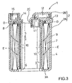
- FIG. 1 is a plan view showing the filter unit 1 according to the first embodiment
- FIG. 2 is a sectional view taken along line A-C in FIG. 1
- FIG. 3 is a sectional view taken along line B-C in FIG. 1.
- the case 2 of the filter unit 1 consists of a case body 2A and a case cap 2B, both of which are made of an electrically conductive resin or a non-conductive resin.
- the case body 2A is a double cylindrical structure with a bottom that includes an inner peripheral wall 3, an outer peripheral wall 4, and a generally annular bottom wall 3A that connects the inner and outer peripheral walls 3 and 4.
- the case 2 has a generally D-shaped cross-section. Specifically, as best shown in FIG. 5, a peripheral portion of the outer peripheral wall 4 is cut away to terminate at peripheral ends 4A.
- the peripheral ends 4A of the outer peripheral wall 4 are connected to the inner peripheral wall 3 through sidewall 3B.
- the filter element 7 is inserted into a generally C-shaped space between the inner peripheral wall 3 and the outer peripheral wall 4. Then, the case cap 2B closes the open top of the case body 2A. Thus, the case 2 is formed and the filter unit 1 is constructed. At this time, the generally C-shaped shield element 8A is in tight contact with the case cap 2B, which prevents fuel from passing through a clearance that may otherwise be made between the filter element 7 and the case cap 2B. The generally C-shaped shield element 8C is also in tight contact with the bottom plate 3A, which prevents fuel from passing through a clearance that may otherwise be made between the filter element 7 and the bottom plate 3A.
- the generally linear shield elements 8B are in tight contact with the side wall 3B, which prevents fuel from passing through a clearance that may otherwise be made between the filter element 7 and the side walls 3B.
- the space having a generally C-shaped cross-section between the inner peripheral wall 3 and the outer peripheral wall 4 is partitioned off by the filter element 7 to have a water-tight seal. If the filter element 7 or the case 2 itself has a shielding function, the shield element 8 is not required to partition the space into an outer space and an inner space by the filter element 7 so as to be water-tight.
- the case cap 2B has an inlet mounting hole 11 that communicates with a fuel inlet chamber 9 (the space surrounded by the filter element 7 and the outer peripheral wall 4) through a fuel path 12 and a fuel inlet port 13. Further, as best shown in FIG. 3, the case cap 2B has an outlet mounting hole 15 that communicates with a fuel outlet chamber 10 (the space surrounded by the filter element 7 and the inner peripheral wall 3) through a fuel outlet port 14.
- the generally C-shaped shield element 8 is fixed in a position offset from the center of the curvature of the filter element 7, so that the relatively large fuel inlet port 13 can be formed on the outer peripheral side of the filter element 7 (to be exact, the shield element 8) and the relatively large fuel outlet port 14 also can be formed on the inner peripheral side thereof.
- the shield element 8 is displaced inwardly on the right side of FIG. 1 to ensure a large space on the outer peripheral side thereof, while the shield element 8 is displaced outwardly on the left side of FIG. 1 to ensure a large space on the inner peripheral side thereof.
- a sufficiently large area for the openings of the fuel inlet port 13 and the fuel outlet port 14 is ensured.
- a cylindrical portion 16 is formed on the upper surface of the case cap 2B and is adapted to receive return fuel from an engine or a pressure regulator.
- the cylindrical portion 16 has a bottom surface that is closed by case cap 2B and has a plurality of openings 17 formed on the side thereof. Fuel flows into the cylinder 16, flows out through the plurality of openings 17 and flows radially from the cylindrical portion 16 along the surface of the case cap 2B.
- An opening 2C is formed in the case cap 2B above a pump accommodating space 5. When a small amount of fuel remains in the tank and the opening 2C is exposed above the surface of the remaining fuel, some of the fuel flowing along the surface of the case cap 2B runs into the opening 2C.
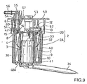
- the space 5 for accommodating a pump 30 is defined inside the inner peripheral wall 3 of the case body 2A. As shown in FIG. 9, the pump 30 is inserted into the pump accommodating space 5 through an opening 6 in the bottom side of the case body 2A. When the pump 30 is inserted into the pump accommodating space 5, a delivery port 31 of the pump 30 is connected to the inlet mounting hole 11 of the case 2 by means of a spacer 32 and a bushing 33.
- the integral assembly of the pump 30 and the filter unit 1 is further enclosed in a housing, which integral assembly is simply referred to as a filter.
- the housing consists of a housing body 40 and a housing cap 50, which are both made of a nonconductive resin.
- the housing body 40 and the housing cap 50 comprise a cover that forms a surface of the filter.
- the housing body 40 is cylindrical and has a bottom formed with an opening 40A and an open top.
- the integral assembly of the pump 30 and the filter unit 1 is inserted into the housing body 40 from the open top.
- Support element 41 is made of a nonconductive material, such as a nonconductive resin.
- the housing body 40 has a D-shaped cross-section to conform to the outside configuration of the case 2.
- a return pipe fitting 56 for return fuel and a feed pipe fitting 58 for drawing fuel from the tank extend through the housing cap 50 and are fixed to the housing cap 50.
- An opening 54 of the feed pipe fitting 58 that opens at the underside of the cap 50 is formed in a position corresponding to the outlet mounting hole 15 shown in FIG. 1.
- an opening 57 of the return pipe fitting 56 that opens at the underside of the cap 50 is formed in a position corresponding to the cylinder 16 shown in FIG. 1.
- the outlet mounting hole 15 of the case 2 is connected to the opening 54 of the feed pipe fitting 58 via a fuel supply pipe 60 and an O-ring 61. Further, the opening 57 of the return pipe fitting 56 is disposed opposite to the cylinder 16 formed on the case 2. A hose may be used to connect the opening 57 to the cylinder 16.
- Designated at 52 is a cushion for positioning the integral assembly of the pump 30 and the filter unit 1 and the housing (the housing body 40 and the housing cap 50).
- Designated at 53 is a power supply connector. A power terminal of the pump 30 is connected to the connector 53.
- the integral assembly of the pump 30 and the filter unit 1 is assembled with the housing body 40 and the housing cap 50 to form a one-piece filter.
- the filter is inserted into and fixed to the tank (not shown).
- the surface of the filter comprises a nonconductive resin cover (the housing body 40 and the housing cap 50).
- the pump 30 draws fuel from the tank via the primary filter 34 and then directs the fuel into the fuel inlet chamber 9 through the delivery port 31, the fuel path 12 and the fuel inlet port 13.
- the fuel that has been directed into the fuel inlet chamber 9 radially passes through the filter material 7D of the filter element 7 and is directed into the fuel outlet chamber 10.
- the fuel is filtered.
- the filtered fuel is discharged out to the feed pipe fitting 58 through the fuel outlet port 14, the fuel supply pipe 60, and fuel path 55.
- One end of a feed pipe (not shown) is connected to the feed pipe fitting 58 and the other end thereof is connected to a fuel injector.
- the feed pipe is connected to a pressure regulator (not shown), which discharges the fuel when the fuel pressure within the feed pipe exceeds a predetermined value.
- the return pipe is connected to a fuel discharge port for discharging the fuel.
- the fuel that has been discharged into the return pipe is directed into the cylinder 16 through the return pipe fitting 56.
- the fuel then flows out through the plurality of openings 17 onto the surface of the case cap 2B.
- a portion of the flowing fuel runs down into the clearance between the pump 30 and the inner peripheral wall 3 of the case 2.
- most of the return fuel runs down into the clearance between the outer peripheral wall 4 of the case 2 and the housing body 40. Consequently, the inner and outer peripheral walls 3 and 4 of the case 2 and the inner surface of the housing 40 always contact the fuel.
- the fuel that has returned via the return pipe runs down along the outer periphery of the pump 30 and the outer periphery of the case body 2A. These fuel paths have a long peripheral length and hence a large cross-sectional area. Therefore, the fuel slowly runs down in a thin film-like sheet around the pump 30 and the case body 2A. As a result, sounds produced by the return of the fuel can be reduced.
- the housing body 40 and the housing cap 50 become electrically charged.
- the electric charge does not readily build up on the surface of the housing body 40 and the housing cap 50 when a relatively large amount of fuel remains in the tank and thus, the housing body 40 and the housing cap 50 contact the fuel across a relatively large area.
- electric charge tends to readily build up on the surface of the housing body 40 and the housing cap 50 when the amount of the fuel remaining in the tank is reduced and thus, the housing body 40 and the housing cap 50 contact the fuel in a smaller area.
- the discharging environment of the filter of the present invention which is used within a tank, is totally different from that of the filter shown in WO92/04097, which is used outside of a tank. If the filter is used within a tank, the filter is covered with fuel vapor, even if a small amount of fuel remains in the tank and the filter is exposed above the fuel surface. Therefore, the filter presents a different discharging property from that of a filter disposed in a gas atmosphere.
- the charging potential of the filter cover can be decreased to a considerable degree by utilizing return fuel to accelerate electric discharge. Therefore, in the case of an in-tank filter system, if the filter element is of a type that does not readily become charged, the surface of the filter case will not be destroyed, even if it is nonconductive. Rather, corona discharges are continuously generated from the nonconductive filter surface. As a result, the discharging potential of the filter is not increased to such an extent that the life of the resin filter cover is shortened. Further, even if the filter surface is brought into contact with or close to the tank during maintenance or repair operations, movement of the charge is restrained because the filter surface has a large bulk resistivity. Consequently, generation of spark discharge can be effectively restrained.
- a filter element is used in which fuel passes radially through the filter element and the outermost surface of the filter is made of a nonconductive material. If this filter is used within the tank, not only the discharging potential that is generated in the filter element is reduced, but the surface potential of the filter is also reduced by corona discharge being generated from the filter surface. Further, spark discharge is not readily generated because the filter surface is made of a nonconductive material that has high bulk resistivity. When the filter surface is made of a nonconductive material, even if the filter surface is brought into contact with the tank during some operation, charge that has built up on the filter surface (housing body 40 in this embodiment) does not move away rapidly. Consequently, generation of spark discharge can be effectively restrained.
- FIG. 18 shows the relation of the electric discharge energy and the charging potential to the bulk resistivity of the element that forms the filter surface.
- the bulk resistivity is 10 8 to 10 10 ⁇ cm
- electric discharge energy is held low and at the same time the charging potential is also held low.
- the electric discharge energy and the charging potential are in a good balance within the range from 10 8 to 10 10 ⁇ cm. Therefore, it is preferable to choose the filter case material from materials that have a bulk resistivity within the above range.
- the filter element 7 is enclosed in the case 2 and the case 2 is accommodated within the housing body 40 and the housing cap 50.
- the filter element 7 is doubly covered.
- the outer cover (the housing body 40 and the housing cap 50 in this embodiment) is nonconductive, the principle of the present invention is achieved.
- the inner cover (case 2 in this embodiment) may be made of either type of material, i.e. conductive or nonconductive. In either case, continuous corona discharge can be obtained from the outer cover (the housing body 40 and the housing cap 50) and deterioration of the filter cover can be effectively prevented.
- return fuel flows along the surfaces of the case 2, the housing body 40 and the housing cap 50, so that the electric charge that has built up on the surfaces of the case 2, the housing body 40 and the housing cap 50 is reduced.
- This charge reducing effect that results by causing the return fuel to run along the case and the housing, is effective when the fuel remaining in the tank is reduced and the contact area of the housing with the fuel in the tank is also reduced, so that the electric charge on the filter surface will not readily discharged.
- the return fuel that has been received in the cylinder 16 is directed through the plurality of openings 17 to a wider surface area of the case cap 2B, so that the charging potential of the surface of the case 2 or the housing can be uniformly decreased over the entire surface area.
- the passing area is the peripheral direction length multiplied by the height.
- the passing area is the peripheral direction length multiplied by the thickness of the filter material.
- the former is far greater than the latter. Therefore, if the amount of fuel that is filtered per unit time is equal, the passing flow rate is lower in the case of the former filter than in the latter filter.
- the amount of electric charge (charging potential) that builds up on the filter when the fuel passes through the filter depends on the passing flow rate of the fuel. As the flow rate increases, the charging potential also increases.
- FIG. 11 shows the relationship between the flow rate and the charging potential. The charging potential is higher for (a) a filter through which fuel flows axially at a higher rate and lower for (b) a filter through which fuel flows radially at a lower rate.
- the discharging potential that builds up on the filter is also influenced by the time required for the fuel to pass through the filter.
- the contact time of the filter with the fuel is relatively short because of the thinness of the filter element, notwithstanding the fact that the fuel flow rate is relatively low.
- the contact time of the filter with the fuel is relatively long, because the fuel must pass through the height of the filter element, notwithstanding the fact that the fuel flow rate is relatively high. Therefore, using a radial-flow filter instead of an axial-flow filter can considerably decrease the amount of electric charge that is generated on the filter.
- the inventors have verified that generation of spark discharges can be prevented by using a filter element that has a small amount of electric charge because the fuel flows radially and by covering the filter element with a nonconductive element. On the basis of such verification, the inventors have proposed the present invention.
- both the case and the housing cover the filter element.
- at least the outer cover should be nonconductive. It does not matter if the inner cover is conductive or nonconductive.
- the cover for covering the filter element may be of a single structure.
- the housing may be eliminated and the case 2 may comprise the outermost surface. In this case, the case 2 must be nonconductive.
- FIGS. 12 and 13 show a filter in which a pressure regulator 80 as well as a pump 30, a housing body 40 and a housing cap 70 are assembled with the filter unit 1 shown in FIGS. 1 to 3.
- FIG. 13 is a sectional view taken along line G-G in FIG. 14.
- the fuel pump 30 is assembled in the case 2 of the filter unit 1 and the case 2 is enclosed in the housing body 40.
- the housing body 40 is then covered with the housing cap 70.
- the pressure regulator 80 is mounted via the O-ring 61 between the outlet mounting hole 15 of the case 2 and a mounting hole 74 formed in the housing cap 70.
- the mounting hole 74 is connected to a feed pipe fitting 76 via a fuel path 75.
- the fuel discharge port of the pressure regulator 80 is positioned opposite to or connected to the cylinder 16 for receiving return fuel.
- a power terminal of the fuel pump 30 is connected to a power supply connector 73 and the cushion 52 and the primary filter 34 are also provided.
- Fuel pumped by the fuel pump 30 is directed to the pressure regulator 80 through the delivery port 31, the fuel path 12, the fuel inlet port 13, the fuel inlet chamber 9, the filter element 7, the fuel outlet chamber 10 and the fuel outlet port 14.
- the pressure regulator 80 discharges the fuel from the fuel discharge port to the return fuel receiving cylinder 16 when the fuel pressure within the fuel path 75 exceeds a predetermined value.
- the fuel discharged into the cylinder 16 flows through the plurality of openings 17 of the cylinder 16 and along the surface of the case 2 back to the liquid fuel.
- the fuel pressure within the fuel path 75 is maintained at a set pressure.
- the fuel adjusted to the set pressure is supplied to a fuel injector through the feed pipe fitting 76 and a feed pipe (not shown).
- FIG. 14 shows the filter module assembled with a sensor and other attachments.
- a mounting portion 80 is provided in the remaining space cut out from the cylindrical configuration that defines a configuration of the housing body 40 having a D-shaped cross section.
- a sensor 85 such as a fuel gauge or a thermistor, is attached to the housing body 40 by engaging an engaging portion 86 of the sensor 85 with a groove 81 of the mounting portion 80.
- the outer diameter of the filter with such attachments is substantially equal to the housing body 40. Therefore, the filter module can be inserted into the tank through a circular mounting hole in the tank.
- the case is contained within the housing, and the housing is made of a nonconductive material.
- the case also ma be used as the housing.
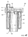
- FIGS. 15 and 16 This embodiment is shown in FIGS. 15 and 16.
- FIG. 15 is a sectional view of a filter unit 100
- FIG. 16 is a sectional view of a filter formed by assembling a pump or other elements on the filter unit.
- a case 102 constitutes the surface of the filter.
- the case 102 of the filter unit 100 is made of a nonconductive material, such as a nonconductive resin.
- the case 102 has an inner peripheral wall 103 and an outer peripheral wall 104.
- a filter element 107 is mounted between the inner peripheral wall 103 and the outer peripheral wall 104 via a shield element 108 such that a fuel inlet chamber and a fuel outlet chamber are formed on the outer peripheral side and on the inner peripheral side of the filter element 107.
- a fuel outlet port 114 is provided to communicate with the fuel outlet chamber and has an outlet mounting hole 115 and a mounting hole 116 for mounting a pressure regulator 130.
- the case 102 has a hole 118 for mounting a set plate 150 on the top surface, has an inserting port 106 for inserting the pump 30 and an engaging portion 117 for mounting a cover 160 on the bottom surface.
- the pump 30 is inserted through the inserting port 106 of the case 102 and the pressure regulator 130 is connected to the mounting hole 116. Then, the set plate 150 is mounted on the case 102 by engaging an engaging portion 151 with the hole 118 of the case 102. At this time, a fuel supply pipe 155 is mounted between the outlet mounting hole 115 of the case 102 and a mounting hole 154 of the set plate 150. Further, the primary filter 34 is connected to the suction port of the fuel pump 30. Then, the cover 160 is mounted on the case 102 by engaging the engaging portion 117 of the case 102 with a hole 161 of the cover 160.
- the filter has been described as being formed by assembling the fuel pump within the fuel filter unit.
- the fuel filter unit may be singly disposed for use within the tank.
- the cross-sectional shape of the case has been described as being D-shaped, but it may be circular, C-shaped, or various other shapes.
- the housing and the case have been described as being made of nonconductive materials and the return fuel has been described as being directed along the surface of the case, it may be designed to satisfy only one of these conditions.
- the fuel filter has been described as having a structure in which the case is contained in the housing or in which the case is used also as a housing, but the structure of the fuel filter is not limited to these structures.
- the structure of the fuel filter is not limited to these structures.
- at least the outer peripheral surface that is most likely to be brought into contact with the tank may be made of a nonconductive material.
- the surface of the filter is made of a nonconductive material.
- the electric charge does not rapidly move when the electric charge built up on the surface of the filter is discharged. Therefore, with a filter having a simple construction, spark discharge can be prevented from being generated by electric charge that will be generated when the fuel passes through the fuel filter.
Landscapes
- Engineering & Computer Science (AREA)
- Chemical & Material Sciences (AREA)
- Combustion & Propulsion (AREA)
- Mechanical Engineering (AREA)
- General Engineering & Computer Science (AREA)
- Chemical Kinetics & Catalysis (AREA)
- Cooling, Air Intake And Gas Exhaust, And Fuel Tank Arrangements In Propulsion Units (AREA)
- Filtration Of Liquid (AREA)
Claims (5)
- Innerhalb eines Kraftstofftanks angeordnetes Filtersystem, enthaltend:wobei das insgesamt zylindrische Filterelement von einer Bauart ist, die Fremdmaterialien aus dem Kraftstoff dadurch herausfiltert, dass der Kraftstoff radial durch es hindurchströmt,eine insgesamt zylindrische Pumpe (30);einen insgesamt doppelzylindrischen Filtermantel (2; 91; 102), der um einen äußeren Umfang der Pumpe herum angeordnet ist und eine innere Umfangswand (3; 103) und eine äußere Umfangswand (4, 104) und ein Paar von oberer und unterer Endumfangswand (3A, 2B) zwischen den beiden Umfangswänden aufweist, wobei wenigstens die Oberfläche des Filtermantels (2; 91; 102) aus einem nichtleitenden Material hergestellt ist;ein insgesamt zylindrisches Filterelement (7; 107), das in dem Filtermantel angeordnet ist und den Filtermantel in eine innere und eine äußere Kammer (109) trennt;einen Durchlass (12, 13), der eine Abgabeöffnung der Pumpe mit einer der Kammern (9) in dem Filtergehäuse verbindet; undeinen Durchlass (14, 15), der die andere der Kammern (10) in dem Filtergehäuse mit einem Kraftstoffdurchlass zur Abgabe von Kraftstoff zur Außenseite eines Kraftstofftanks verbindet;
dadurch gekennzeichnet, dass der Filtermantel (2; 91) einen Aufnahmebereich (16) zur Aufnahme von Rücklaufkraftstoff aufweist und zwischen dem Außenumfang der Pumpe (30) und der inneren Umfangswand (3) des Filtermantels (2) ein Zwischenraum ausgebildet ist, in den der Rücklaufkraftstoff strömt. - Innerhalb eines Kraftstofftanks angeordnetes Filtersystem, enthaltend:wobei das insgesamt zylindrische Filterelement von einer Bauart ist, die Fremdmaterialien aus dem Kraftstoff dadurch herausfiltert, dass der Kraftstoff radial durch es hindurchströmt,eine insgesamt zylindrische Pumpe (30);einen insgesamt doppelzylindrischen Filtermantel (2; 91; 102), der um einen äußeren Umfang der Pumpe herum angeordnet ist und eine innere Umfangswand (3; 103) eine äußere Umfangswand (4; 104) und ein Paar von einer oberen und einer unteren Endumfangswand (3A, 2B) zwischen den beiden Umfangswänden aufweist;ein insgesamt zylindrisches Filterelement (7; 107), das in dem Filtermantel angeordnet ist und den Filtermantel in eine innere und eine äußere Kammer (109) trennt;einen Durchlass (12, 13), der eine Abgabeöffnung der Pumpe mit einer der Kammern (9) des Filtergehäuses verbindet; undeinen Durchlass (14, 15), der die andere der Kammern (10) des Filtergehäuses mit einem Kraftstoffdurchlass zur Abgabe von Kraftstoff zur Außenseite eines Kraftstofftanks verbindet;
dadurch gekennzeichnet, dass der Filtermantel (2; 91) einen Aufnahmebereich (16) zur Aufnahme von Rücklaufkraftstoff aufweist und dass ein Zwischenraum zwischen dem Außenumfang der Pumpe (30) und der inneren Umfangswand (3) des Filtergehäuses (2) gebildet ist, in welchem Zwischenraum der Rücklaufkraftstoff strömt, und dass das Filtersystem weiter enthält
ein Gehäuse (40, 50; 40, 70) zur Aufnahme des Filtermantels (2), welches Gehäuse aus einem nichtleitenden Material besteht und wobei ein Zwischenraum zwischen der äußeren Umfangswand (4) des Filtermantels (2; 91; 102) und dem inneren Umfang des Gehäuses gebildet ist, in welchen Zwischenraum Rücklaufkraftstoff strömt. - Filtersystem nach Anspruch 1 oder 2, dadurch gekennzeichnet, dass das Filterelement (7) ein blattartiges Filtermaterial (70) enthält, das längs einer Mehrzahl paralleler Linien gefaltet ist und insgesamt gebogen ist.
- Filtersystem nach einem der Ansprüche 1 bis 3, dadurch gekennzeichnet, dass ein Druckregler (80; 130) angebaut ist.
- Filtersystem nach einem der Ansprüche 1 bis 4, dadurch gekennzeichnet, dass der Filtermantel (2) aus einem Harz mit einem spezifischen Volumenwiderstand von 108-1010 Ω x cm besteht.
Applications Claiming Priority (7)
| Application Number | Priority Date | Filing Date | Title |
|---|---|---|---|
| JP5648797 | 1997-03-11 | ||
| JP5648897 | 1997-03-11 | ||
| JP5648897 | 1997-03-11 | ||
| JP5648797 | 1997-03-11 | ||
| JP22270697 | 1997-08-19 | ||
| JP22270697 | 1997-08-19 | ||
| PCT/JP1998/001036 WO1998040620A1 (fr) | 1997-03-11 | 1998-03-11 | Filtre a carburant ameliore, resistant a l'electrisation et installe dans un reservoir |
Publications (3)
| Publication Number | Publication Date |
|---|---|
| EP0969200A1 EP0969200A1 (de) | 2000-01-05 |
| EP0969200A4 EP0969200A4 (de) | 2000-06-07 |
| EP0969200B1 true EP0969200B1 (de) | 2004-02-11 |
Family
ID=27295934
Family Applications (1)
| Application Number | Title | Priority Date | Filing Date |
|---|---|---|---|
| EP98907193A Expired - Lifetime EP0969200B1 (de) | 1997-03-11 | 1998-03-11 | Im tank eingebauter brennstofffilter mit verbessertem wiederstand gegen elektrische aufladung |
Country Status (5)
| Country | Link |
|---|---|
| US (1) | US6382190B1 (de) |
| EP (1) | EP0969200B1 (de) |
| JP (1) | JP3566305B2 (de) |
| DE (1) | DE69821603T2 (de) |
| WO (1) | WO1998040620A1 (de) |
Families Citing this family (29)
| Publication number | Priority date | Publication date | Assignee | Title |
|---|---|---|---|---|
| JP3382808B2 (ja) | 1997-02-07 | 2003-03-04 | 株式会社日立ユニシアオートモティブ | 燃料供給装置 |
| DE19926687C2 (de) | 1999-06-11 | 2001-06-13 | Bosch Gmbh Robert | Kraftstofffördermodul mit integriertem Kraftstofffilter und Potentialanschluß |
| JP2002031003A (ja) * | 2000-07-18 | 2002-01-31 | Mitsubishi Electric Corp | 燃料供給装置 |
| US6729308B1 (en) * | 2000-08-18 | 2004-05-04 | Mitsubishi Denki Kabushiki Kaisha | Fuel feed device |
| JP4359806B2 (ja) * | 2001-06-29 | 2009-11-11 | 株式会社デンソー | 燃料供給装置 |
| US6679227B2 (en) * | 2001-11-08 | 2004-01-20 | Delphi Technologies, Inc. | Grounded fuel delivery module for fuel system |
| US6613227B2 (en) * | 2002-01-11 | 2003-09-02 | Kuss Corporation | Electrically conductive in-tank fuel filter |
| JP3783230B2 (ja) * | 2002-03-28 | 2006-06-07 | 株式会社デンソー | ポンプモジュール |
| JP2004011550A (ja) * | 2002-06-07 | 2004-01-15 | Kyosan Denki Co Ltd | 燃料供給装置 |
| US6776185B2 (en) * | 2002-07-03 | 2004-08-17 | Delphi Technologies, Inc. | Grounded jet pump assembly for fuel system |
| US7555946B2 (en) * | 2004-08-30 | 2009-07-07 | Delphi Technologies, Inc. | Sealed fuel level sensors |
| US20060042379A1 (en) * | 2004-08-30 | 2006-03-02 | Ireland Hugh W | Sealed fuel level sensor |
| US7185682B2 (en) * | 2004-12-22 | 2007-03-06 | Visteon Global Technologies, Inc. | Fuel flange assembly for a vehicle fuel system |
| JP2006250040A (ja) * | 2005-03-10 | 2006-09-21 | Aisan Ind Co Ltd | 燃料ポンプ |
| US7467549B2 (en) * | 2005-04-05 | 2008-12-23 | Ti Group Automotive Systems, Llc | Electrostatic charge control for in-tank fuel module components |
| US7527042B2 (en) * | 2005-04-05 | 2009-05-05 | Ti Group Automotive Systems, Llc | Electrostatic charge control for in-tank fuel module components |
| JP4785576B2 (ja) * | 2006-03-17 | 2011-10-05 | 株式会社ケーヒン | 自動二輪車用の燃料供給装置 |
| DE102008005358A1 (de) * | 2007-02-13 | 2008-08-14 | Vdo Automotive Ag | Fördereinheit |
| JP4804404B2 (ja) * | 2007-04-06 | 2011-11-02 | 愛三工業株式会社 | 燃料ポンプ装置及び燃料供給装置 |
| DE102008040479A1 (de) * | 2007-07-23 | 2009-02-05 | Denso Corp., Kariya-shi | Kraftstoffzufuhrvorrichtung |
| US7976712B2 (en) * | 2007-10-01 | 2011-07-12 | Cummins Filtration Ip, Inc. | Apparatus, system, and method for filtration of a dosing fluid in an exhaust aftertreatment system |
| JP4552994B2 (ja) * | 2007-10-12 | 2010-09-29 | 株式会社デンソー | 燃料供給装置 |
| US8372278B1 (en) * | 2012-03-21 | 2013-02-12 | GM Global Technology Operations LLC | Liquid fuel strainer assembly |
| KR101340914B1 (ko) * | 2013-05-23 | 2013-12-13 | 주식회사 코아비스 | 스트레이너 및 이를 포함하는 연료펌프모듈 |
| CN106413843B (zh) * | 2014-05-21 | 2019-08-09 | 曼·胡默尔有限公司 | 过滤元件和过滤器组件 |
| DE102015003101A1 (de) * | 2015-03-11 | 2016-09-15 | Mann + Hummel Gmbh | Filterelement |
| JP6380364B2 (ja) * | 2015-12-17 | 2018-08-29 | 株式会社デンソー | 燃料ポンプ及び燃料ポンプモジュール |
| DE102016012936A1 (de) * | 2016-10-27 | 2018-05-03 | Mann + Hummel Gmbh | Flüssigkeitsreinigungselement, Flüssigkeitsreinigungssystem und Verfahren zur Herstellung eines Flüssigkeitsreinigungselements |
| KR102178858B1 (ko) * | 2019-09-25 | 2020-11-13 | 주식회사 코아비스 | 연료펌프용 스트레이너 |
Family Cites Families (35)
| Publication number | Priority date | Publication date | Assignee | Title |
|---|---|---|---|---|
| JPS5537584A (en) | 1978-09-11 | 1980-03-15 | Tsuchiya Mfg Co Ltd | Lubricating oil filter and lubricating oil filter system |
| JPS6224005Y2 (de) * | 1978-12-15 | 1987-06-19 | ||
| JPS5588005A (en) | 1978-12-26 | 1980-07-03 | Fuji Photo Film Co Ltd | Image information reader |
| JPS5836849Y2 (ja) * | 1980-02-15 | 1983-08-19 | 日産自動車株式会社 | 自動車用燃料ポンプ装置 |
| JPS56120356A (en) | 1980-02-29 | 1981-09-21 | Citizen Watch Co Ltd | Dot matrix printer |
| JPS59194071A (ja) | 1983-04-18 | 1984-11-02 | Nifco Inc | 自動車の燃料タンク用フイルタの製造法 |
| US4592836A (en) * | 1984-05-10 | 1986-06-03 | Chiao Yi Shong | Electrostatic engine oil cleaner |
| DE3422979A1 (de) | 1984-06-22 | 1986-01-02 | Robert Bosch Gmbh, 7000 Stuttgart | Filter fuer dieselkraftstoff |
| JP2648671B2 (ja) | 1988-08-03 | 1997-09-03 | 株式会社ウオルブローフアーイースト | 携帯作業機の電動式始動燃料ポンプ |
| JP2819667B2 (ja) | 1989-09-14 | 1998-10-30 | 株式会社デンソー | 車両用燃料供給装置 |
| JPH04109465A (ja) | 1990-08-29 | 1992-04-10 | Hitachi Ltd | 磁気デイスク装置のキヤリツジ |
| US5076920B2 (en) | 1990-08-30 | 1998-05-05 | Allied Signal Inc | Electrostatically dissipative fuel filter |
| US5085773A (en) | 1990-11-06 | 1992-02-04 | Allied-Signal Inc. | Anti-static fuel filter |
| JP3286957B2 (ja) | 1992-03-06 | 2002-05-27 | ヤマハ発動機株式会社 | 自動二輪車用エンジンの燃料供給装置及びv型エンジン |
| GB2304821B (en) | 1992-12-15 | 1997-05-07 | Bosch Gmbh Robert | Fuel supply equipment for a vehicle fuel supply system |
| DE4242242C2 (de) | 1992-12-15 | 2003-04-30 | Bosch Gmbh Robert | Vorrichtung zum Versorgen der Brennkraftmaschine eines Kraftfahrzeuges mit in einem Vorratstank vorhandenem Kraftstoff |
| US5607578A (en) | 1993-05-06 | 1997-03-04 | Aisan Kogyo Kabushiki Kaisha | Filter system for an in-tank fuel pump |
| US5380432A (en) * | 1993-05-13 | 1995-01-10 | Parr Manufacturing, Inc. | Fuel filter with electrostatic charge preventing media |
| JP3734281B2 (ja) | 1993-09-10 | 2006-01-11 | 株式会社デンソー | インタンク式燃料ポンプ |
| DE4417713A1 (de) | 1994-05-20 | 1995-11-23 | Teves Gmbh Alfred | Austauschsatz für ein Wischblatt |
| FR2724692B1 (fr) | 1994-09-15 | 1997-01-24 | Marwal Systems | Ensemble de pompage incorporant un regulateur de pression, pour reservoir de carburant de vehicule automobile et reservoir ainsi equipe |
| DE4433301C2 (de) | 1994-09-19 | 1998-07-02 | Mannesmann Vdo Ag | Tankdeckel |
| KR100302448B1 (ko) * | 1994-11-04 | 2002-07-02 | 오카메 히로무 | 연료공급장치 |
| DE4444854C2 (de) * | 1994-12-16 | 2002-10-24 | Bosch Gmbh Robert | Förderaggregat |
| WO1996023967A1 (fr) | 1995-02-03 | 1996-08-08 | Nippondenso Co., Ltd. | Dispositif d'alimentation en carburant |
| DE19509143C2 (de) | 1995-03-14 | 2003-04-10 | Pierburg Gmbh | Brennstoffördereinrichtung für eine Brennkraftmaschine |
| JP3388946B2 (ja) | 1995-06-23 | 2003-03-24 | 愛三工業株式会社 | 燃料ポンプ装置 |
| DE19530526C2 (de) * | 1995-08-19 | 1997-12-18 | Knecht Filterwerke Gmbh | Kraftstoffilter mit einem elektrisch leitfähigen Gehäuse für insbesondere Kraftfahrzeuge |
| JPH09126178A (ja) | 1995-10-27 | 1997-05-13 | Aisan Ind Co Ltd | 燃料ポンプ装置 |
| US5762047A (en) * | 1996-02-14 | 1998-06-09 | Mitsubishi Denki Kabushiki Kaisha | Fuel supplying apparatus |
| JP3389010B2 (ja) * | 1996-07-02 | 2003-03-24 | 愛三工業株式会社 | 燃料フィルタ |
| JPH1089188A (ja) | 1996-07-23 | 1998-04-07 | Aisan Ind Co Ltd | 燃料フィルタ |
| JP3382808B2 (ja) | 1997-02-07 | 2003-03-04 | 株式会社日立ユニシアオートモティブ | 燃料供給装置 |
| US5900145A (en) | 1997-08-22 | 1999-05-04 | J & K Environmental Ltd. | Liquid crystal stationary phases for chromatography |
| DE19813204A1 (de) * | 1998-03-25 | 1999-09-30 | Bosch Gmbh Robert | Flansch eines Kraftstoff-Fördermoduls und Kraftstoff-Fördermodul |
-
1998
- 1998-03-11 WO PCT/JP1998/001036 patent/WO1998040620A1/ja active IP Right Grant
- 1998-03-11 US US09/380,590 patent/US6382190B1/en not_active Expired - Lifetime
- 1998-03-11 DE DE69821603T patent/DE69821603T2/de not_active Expired - Fee Related
- 1998-03-11 JP JP53944798A patent/JP3566305B2/ja not_active Expired - Fee Related
- 1998-03-11 EP EP98907193A patent/EP0969200B1/de not_active Expired - Lifetime
Also Published As
| Publication number | Publication date |
|---|---|
| DE69821603T2 (de) | 2005-01-05 |
| WO1998040620A1 (fr) | 1998-09-17 |
| DE69821603D1 (de) | 2004-03-18 |
| US6382190B1 (en) | 2002-05-07 |
| EP0969200A1 (de) | 2000-01-05 |
| EP0969200A4 (de) | 2000-06-07 |
| JP3566305B2 (ja) | 2004-09-15 |
Similar Documents
| Publication | Publication Date | Title |
|---|---|---|
| EP0969200B1 (de) | Im tank eingebauter brennstofffilter mit verbessertem wiederstand gegen elektrische aufladung | |
| EP0754852B1 (de) | Im Tank angeordneter Brennstoffpumpensatz mit Vorrichtung zum Abführen elektrostatischer Ladungen | |
| US6168713B1 (en) | Electrostatic charge removing apparatus | |
| EP1388664B1 (de) | Pumpenmodul | |
| US5785032A (en) | Fuel supply system | |
| AU642616B2 (en) | Electrostatically dissipative fuel filter | |
| US6123521A (en) | Fuel supply system having a pump with a resiliently mounted filter | |
| US6220227B1 (en) | Fuel supply device | |
| US5382359A (en) | Plastic fuel filter with conductive coating for providing an evaporative barrier and for dissipating electrostatic charges | |
| US5380432A (en) | Fuel filter with electrostatic charge preventing media | |
| EP0852293B1 (de) | Brennstoffilter | |
| WO1999030027A1 (fr) | Dispositif d'alimentation en carburant | |
| JP2006177360A (ja) | 自動車燃料システムのための燃料フランジ組立体 | |
| JPH09310648A (ja) | 燃料フィルタ | |
| KR100281776B1 (ko) | 연료필터 | |
| US20070241036A1 (en) | Filter for filtering fuel | |
| KR100663814B1 (ko) | 연료 공급 장치 | |
| JP2001012328A (ja) | 燃料を貯蔵タンクから内燃機関へ供給するための装置、燃料供給モジュール、及び内燃機関のための燃料供給機構 | |
| US6253738B1 (en) | Fuel feeder | |
| JP2003293885A (ja) | インタンク式燃料フィルタ | |
| JP3562614B2 (ja) | 燃料フィルタ | |
| JP3994929B2 (ja) | ポンプモジュール | |
| JP2003269277A (ja) | 燃料供給装置 | |
| US6575199B1 (en) | Fluid supply pipe | |
| US20080251149A1 (en) | Fuel pump housing |
Legal Events
| Date | Code | Title | Description |
|---|---|---|---|
| PUAI | Public reference made under article 153(3) epc to a published international application that has entered the european phase |
Free format text: ORIGINAL CODE: 0009012 |
|
| 17P | Request for examination filed |
Effective date: 19990929 |
|
| AK | Designated contracting states |
Kind code of ref document: A1 Designated state(s): DE IT |
|
| A4 | Supplementary search report drawn up and despatched |
Effective date: 20000420 |
|
| AK | Designated contracting states |
Kind code of ref document: A4 Designated state(s): DE IT |
|
| RIC1 | Information provided on ipc code assigned before grant |
Free format text: 7F 02M 37/10 A, 7F 02M 37/22 B |
|
| 17Q | First examination report despatched |
Effective date: 20020204 |
|
| RAP1 | Party data changed (applicant data changed or rights of an application transferred) |
Owner name: TOKYO ROKI CO., LTD. Owner name: AISAN KOGYO KABUSHIKI KAISHA |
|
| GRAP | Despatch of communication of intention to grant a patent |
Free format text: ORIGINAL CODE: EPIDOSNIGR1 |
|
| GRAS | Grant fee paid |
Free format text: ORIGINAL CODE: EPIDOSNIGR3 |
|
| GRAA | (expected) grant |
Free format text: ORIGINAL CODE: 0009210 |
|
| AK | Designated contracting states |
Kind code of ref document: B1 Designated state(s): DE IT |
|
| REF | Corresponds to: |
Ref document number: 69821603 Country of ref document: DE Date of ref document: 20040318 Kind code of ref document: P |
|
| PGFP | Annual fee paid to national office [announced via postgrant information from national office to epo] |
Ref country code: DE Payment date: 20040401 Year of fee payment: 7 |
|
| PLBE | No opposition filed within time limit |
Free format text: ORIGINAL CODE: 0009261 |
|
| STAA | Information on the status of an ep patent application or granted ep patent |
Free format text: STATUS: NO OPPOSITION FILED WITHIN TIME LIMIT |
|
| 26N | No opposition filed |
Effective date: 20041112 |
|
| PG25 | Lapsed in a contracting state [announced via postgrant information from national office to epo] |
Ref country code: IT Free format text: LAPSE BECAUSE OF NON-PAYMENT OF DUE FEES Effective date: 20050311 |
|
| PG25 | Lapsed in a contracting state [announced via postgrant information from national office to epo] |
Ref country code: DE Free format text: LAPSE BECAUSE OF NON-PAYMENT OF DUE FEES Effective date: 20051001 |