EP0967374B1 - Bedienungshandgriff für ein motorgetriebenes Gerät - Google Patents
Bedienungshandgriff für ein motorgetriebenes Gerät Download PDFInfo
- Publication number
- EP0967374B1 EP0967374B1 EP99112280A EP99112280A EP0967374B1 EP 0967374 B1 EP0967374 B1 EP 0967374B1 EP 99112280 A EP99112280 A EP 99112280A EP 99112280 A EP99112280 A EP 99112280A EP 0967374 B1 EP0967374 B1 EP 0967374B1
- Authority
- EP
- European Patent Office
- Prior art keywords
- cam
- lever
- throttle
- friction member
- unit according
- Prior art date
- Legal status (The legal status is an assumption and is not a legal conclusion. Google has not performed a legal analysis and makes no representation as to the accuracy of the status listed.)
- Expired - Lifetime
Links
- 230000007246 mechanism Effects 0.000 claims description 52
- 230000033001 locomotion Effects 0.000 claims description 36
- 230000002093 peripheral effect Effects 0.000 claims description 19
- 230000004044 response Effects 0.000 claims description 6
- 230000001105 regulatory effect Effects 0.000 claims description 5
- 239000002184 metal Substances 0.000 description 14
- 210000003813 thumb Anatomy 0.000 description 9
- 239000000428 dust Substances 0.000 description 8
- 230000000994 depressogenic effect Effects 0.000 description 7
- 239000000126 substance Substances 0.000 description 7
- 238000010276 construction Methods 0.000 description 5
- 230000009471 action Effects 0.000 description 4
- 210000003811 finger Anatomy 0.000 description 4
- 230000007935 neutral effect Effects 0.000 description 4
- 230000007423 decrease Effects 0.000 description 3
- 230000003247 decreasing effect Effects 0.000 description 3
- 230000008859 change Effects 0.000 description 2
- 230000000052 comparative effect Effects 0.000 description 2
- 238000011109 contamination Methods 0.000 description 2
- 239000010813 municipal solid waste Substances 0.000 description 2
- 239000007921 spray Substances 0.000 description 2
- 230000003213 activating effect Effects 0.000 description 1
- 230000002411 adverse Effects 0.000 description 1
- 230000032683 aging Effects 0.000 description 1
- 230000004323 axial length Effects 0.000 description 1
- 230000005540 biological transmission Effects 0.000 description 1
- 230000000295 complement effect Effects 0.000 description 1
- 230000006835 compression Effects 0.000 description 1
- 238000007906 compression Methods 0.000 description 1
- 230000001276 controlling effect Effects 0.000 description 1
- 230000006866 deterioration Effects 0.000 description 1
- 230000000694 effects Effects 0.000 description 1
- 239000012530 fluid Substances 0.000 description 1
- -1 leaves Substances 0.000 description 1
- 230000003387 muscular Effects 0.000 description 1
- 230000035939 shock Effects 0.000 description 1
- 238000009966 trimming Methods 0.000 description 1
Images


Classifications
-
- F—MECHANICAL ENGINEERING; LIGHTING; HEATING; WEAPONS; BLASTING
- F02—COMBUSTION ENGINES; HOT-GAS OR COMBUSTION-PRODUCT ENGINE PLANTS
- F02B—INTERNAL-COMBUSTION PISTON ENGINES; COMBUSTION ENGINES IN GENERAL
- F02B63/00—Adaptations of engines for driving pumps, hand-held tools or electric generators; Portable combinations of engines with engine-driven devices
- F02B63/02—Adaptations of engines for driving pumps, hand-held tools or electric generators; Portable combinations of engines with engine-driven devices for hand-held tools
-
- Y—GENERAL TAGGING OF NEW TECHNOLOGICAL DEVELOPMENTS; GENERAL TAGGING OF CROSS-SECTIONAL TECHNOLOGIES SPANNING OVER SEVERAL SECTIONS OF THE IPC; TECHNICAL SUBJECTS COVERED BY FORMER USPC CROSS-REFERENCE ART COLLECTIONS [XRACs] AND DIGESTS
- Y10—TECHNICAL SUBJECTS COVERED BY FORMER USPC
- Y10T—TECHNICAL SUBJECTS COVERED BY FORMER US CLASSIFICATION
- Y10T74/00—Machine element or mechanism
- Y10T74/20—Control lever and linkage systems
- Y10T74/20396—Hand operated
- Y10T74/20402—Flexible transmitter [e.g., Bowden cable]
- Y10T74/2042—Flexible transmitter [e.g., Bowden cable] and hand operator
- Y10T74/20438—Single rotatable lever [e.g., for bicycle brake or derailleur]
-
- Y—GENERAL TAGGING OF NEW TECHNOLOGICAL DEVELOPMENTS; GENERAL TAGGING OF CROSS-SECTIONAL TECHNOLOGIES SPANNING OVER SEVERAL SECTIONS OF THE IPC; TECHNICAL SUBJECTS COVERED BY FORMER USPC CROSS-REFERENCE ART COLLECTIONS [XRACs] AND DIGESTS
- Y10—TECHNICAL SUBJECTS COVERED BY FORMER USPC
- Y10T—TECHNICAL SUBJECTS COVERED BY FORMER US CLASSIFICATION
- Y10T74/00—Machine element or mechanism
- Y10T74/20—Control lever and linkage systems
- Y10T74/20576—Elements
- Y10T74/20636—Detents
- Y10T74/2066—Friction
Definitions
- the present invention relates to an operation-control lever unit for regulating power of an engine of an engine-powered working machine to control operation of a working tool of the engine-powered working machine.
- the engine-powered working machine may include a carrying bush cutter, a chemical sprayer, a vacuum dust collector and so on.
- a carrying bush cutter having a circular cutter driven for rotation by an engine carried on the back of an operator is known from Japanese Utility Model Publication No. (SHO) 63-14035.
- the circular cutter is attached to one end of a hand-operating rod.
- the rod is provided with an operation handle near the other end thereof.
- the operator swings the rod up and down and right and left while gripping the operation handle. With this swinging operation, bushes are cut or removed by the rotating circular cutter.
- a lock mechanism is associated with a throttle lever to temporarily lock the throttle lever in a desired position, so that the work load on the operator can be reduced.
- Typical examples of the prior improvements are disclosed in Japanese Utility Model Publication Nos. (SHO) 53-42661 and (SHO) 55-21536, Japanese Utility Model Laid-open Publication No. (SHO) 60-41539, and Japanese Patent Laid-open Publication No. (HEI) 8-303263.
- the throttle lever is displaced to a predetermined operating position, then locked in this operating position by activating the lock mechanism.
- the lock mechanism is released at need.
- the operation lever unit disclosed in Japanese Utility Model Publication Nos. (SHO) 55-21536 includes a throttle adjustment lever and a throttle release lever provided side by side on the operating handle.
- the operation lever unit is complicated in construction, requires an increased number of structural components, and is uneasy to manipulate.
- a frictional force acting on the throttle lever to lock the same lever in position against pivotal movement tends to decrease and eventually allows the throttle lever to move from the locked position.
- the throttle lever may sometimes return to its original position when the operation lever unit is subjected to vibration.
- the operation lever unit has no means to adjust the frictional force acting on the throttle lever.
- the operation lever unit disclosed in Japanese Utility Model Publication No. (SHO) 53-42661 includes a locking pawl pivotally mounted between the pivot axis of a throttle lever and the pivot axis of a lock lever for operatively interlocking the two levers. Because of the presence of the locking pawl, the operating lever unit is complicated in construction and requires an increased number of structural components.
- the present invention is conceived to solve the foregoing problems associated with the prior art.
- a more specific object of the present invention is to provide a operation-control lever unit for an engine-powered working machine, which includes a throttle lever, a lock lever and a throttle-lever holding mechanism of simple construction having a relatively small number of components.
- Another object of the present invention is to provide an operation-control lever unit for an engine-powered working machine, which is simple in construction and is capable of reliably locking a throttle lever in a desired position to regulate output power of an engine of the engine-powered working machine while keeping good manipulability of a lock lever disposed close to the throttle lever.
- the throttle-lever holding mechanism includes a first cam coaxial with the support shaft and formed integrally with the head portion of the handle, a second cam coaxial with the support shaft and provided on the lock lever, the second cam being co-active with the first cam to displace the lock lever along the support shaft in a first direction away from the first cam, and a resilient means disposed behind the second cam when viewed from the first cam and resiliently urging the second cam toward the first cam.
- the throttle-lever holding mechanism is relatively simple in construction and has a small number of structural components.
- one of the first and second cams has an integral tubular portion coaxial with the support shaft and projecting toward the other cam.
- the other cam has an outer peripheral surface slidably received in the tubular portion.
- the first and second cams each have an annular cam surface having at least one radial ridge. At least one of the ridge of the first cam and the ridge of the second cam has a flat top surface. With this flat top surface, the throttle lever can be stably held in a locked position even when the lock lever is pivoted to some extent.
- the flat top surface is preferably perpendicular to the axis of the support shaft.
- the ridge may have a generally trapezoidal cross-sectional shape.
- the throttle-lever holding mechanism further includes a friction member disposed between the throttle lever and the lock lever and forced against the throttle lever when coaction between the first and second cams displaces the lock lever in the first direction against the resiliency of the resilient means.
- the throttle-lever holding mechanism may also include a second friction member disposed opposite to the first-mentioned friction member with the throttle lever disposed therebetween. The first-mentioned friction member and the second friction member cooperate to grip the throttle lever therebetween when the lock lever is displaced in the first direction.
- the first-mentioned friction member and the second friction member are preferably rubber ring discs mounted on the support shaft.
- the resilient means is disposed between the lock lever and the friction member and urges the lock lever in a second direction to move the second cam toward the first cam and also urges the friction member into contact with the throttle lever.
- the resilient means is preferably a conical spring washer mounted on the support shaft.
- the resilient means may include a first resilient member disposed between the lock lever and the first-mentioned friction member, and a second resilient member disposed between the second friction member and a portion of the support shaft.
- the first resilient member urges the lock lever in a second direction to move the second cam toward the first cam and also urges the first-mentioned friction member into contact with the throttle lever.
- the second resilient member urges the second friction member into contact with the throttle lever.
- the resilient means may be disposed between the lock lever and the friction member urge the lock lever in a second direction to move the second cam toward the first cam.
- the resilient means is operatively separated from the friction member.
- the resilient means is disposed between the lock lever and the friction member, and the throttle-lever holding mechanism further includes a friction adjustment device for varying a preloading on the resilient means to adjust a frictional force acting between the throttle lever and the friction member.
- the support shaft is a screw having a head slidably guided in a first portion of the head portion of the handle and a shank including a screw portion threaded with a second portion of the head portion.
- the resilient means, the friction member and the throttle lever are disposed between the head of the screw and the lock lever.
- the screw forms the friction adjustment device. By turning the screw, the screw moves in an axial direction.
- the screw is preferably a hexagonal socket head cap screw.
- the friction adjustment device may further include a lock nut threaded with the screw portion of the screw to lock the screw in position against movement relative to the head portion.
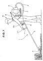
- FIG. 1 there is shown a carrying bush cutter 1 as it is used in a bush-removing work as an engine-powered working machine in which an operation-control lever unit according to the present invention is incorporated.
- the carrying bush cutter 1 includes a frame 2, a power unit such as a gasoline engine 3 mounted on the frame 2, a flexible tube 4 connected at one end to a power output portion of the engine 3, an elongated rigid hollow support rod 5 having one end (proximal end) connected to the other end of the flexible tube 4, and a circular cutter (working tool) 6 rotatably attached to the other end (distal end) of the support rod 5.
- the circular cuter 6 is connected in driven relation to the engine 3 via a flexible power transmission shaft (not shown) extending through the support rod 6 and the flexible tube 4. Thus, the circular cutter 6 is driven in rotation by output power of the engine 3.
- a grip handle 7 and an operation-control handle 10 are provided on a proximal end portion of the support rod 7.
- the operation-control handle 10 is disposed behind the grip handle 7 when viewed from the distal end of the support rod 5.
- the grip handle 7 and the operation-control handle 10 extend orthogonally from an upper surface of the support rod 3.
- the frame 2 has a pair of belts or straps (one being shown in FIG. 1) for enabling the operator M to carry the engine 3 on its back, with a cushioning pad 9 disposed between the back of the operator M and the frame 2.
- the support rod 5 is held on, for example, the right side of a body of the operator M, with the grip handle 7 and the operation-control handle 10 being gripped by the left hand LH and the right hand RH of the operator M, respectively.
- the support rod 5 is swung right and left and up and down about its proximal end so that bushes are cut or removed by the rotating circular cutter 6.
- the left hand LH of the operator M is used essentially for gripping the grip handle 7 and moving the support rod 5 right and left and up and down.
- the right hand RH is used for gripping the operation-control handle 10 and performing throttle adjustment to regulate output power of the engine 3.
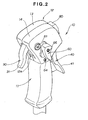
- the operation-control handle 10 constitutes a main part of the operation-control lever unit of the present invention.
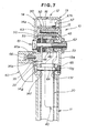
- the operation-control handle 10 is in the form of the grip of a gun and includes a tubular grip portion 11 secured at a lower end to the support rod 5 via a bracket (not shown), and an enlarged head portion 12 secured to an upper end of the grip portion 11.
- the head portion 12 is a hollow member of split structure consisting of left and right head halves or members 13, 14 joined together back to back to form a hollow interior space or pocket in the head portion 12.
- the head portion 12 has an elongate hole or opening 12a formed in a front wall thereof.
- a throttle lever 30 and a lock lever 4C of the operation-control lever unit are pivotally mounted to the head portion 12 within the pocket.
- the throttle lever 30 has a trigger-like lever portion 31 projecting forwardly and downwardly from the elongate opening 12a in the front wall of the head portion 12.
- the lock lever 40 has an actuating lever portion 41 projecting rearwardly and downwardly from an elongate hole or opening 12c (FIG. 5) formed in a rear wall of the head portion 12.
- An engine start switch 80 for starting and stopping the engine 3 (FIG. 1) is provided on the rear wall of the head portion 12 at a position above the opening 12c (FIG. 5). Additionally, a secondary throttle adjustment lever 60 is provided on one side (left side in the illustrated embodiment) of the head portion 12 for achieving fine adjustment of the position of the throttle lever 30.
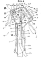
- FIG. 3 shows in perspective the general arrangement of the operation-control lever unit of the present invention.
- the head members 13, 14 have a generally pentagonal dish-like form and each include a planar base 13a, 14a and a peripheral wall 13b, 14b integral with a peripheral edge of the base 13a, 14a and extending perpendicularly to the base 13a, 14a.
- the peripheral wall 13b has four cutout portions 13c, 13d, 13e and 13f formed in consecutive four sides of the pentagonal head member 13.
- the peripheral wall 14b has four cutout portions 14d, 14e (two cutout portions corresponding in position to the cutout portions 13c, 13f being not shown) formed in consecutive four sides of the pentagonal head member 14.
- the cutout portion 13c of the peripheral wall 13b and the corresponding unillustrated cutout portion of the peripheral wall 14b jointly form the above-mentioned elongate opening 12a (FIGS. 1 and 5).
- the cutout portions 13d, 14d jointly form an elongated hole or opening 12b (FIG. 5) from which the engine start switch 60 projects outwardly.
- the cutout portions 13e, 14e jointly form the above-mentioned elongated opening 12c (FIG. 5) which allows pivotal movement of the lock lever 40.
- the head member 13 has an integral cylindrical sleeve 15 projecting perpendicularly from an inside surface of the planar base 13a.
- the sleeve 15 is located near a front end of the head portion 12.
- the head member 14 also has an integral cylindrical sleeve 16 projecting perpendicularly from an inside surface of the planar base 14a.
- the sleeve 16 is aligned with the sleeve 15.
- the sleeve 15 of the head member 13 has a through-hole, while the sleeve 16 of the head member 14 has an internally threaded blind hole closed at one end by the base 14a.
- the head members 13, 14 further have a pair of aligned cylindrical sleeves 17, 18 projecting perpendicularly from respective inside surfaces of the planar bases 13a, 14a at a position located near a rear end of the head members 13, 14.
- the sleeve 17 has a through-hole, while the sleeve 18 has an internally threaded blind hole closed by the base 14a.
- the sleeve 18 is longer than the sleeve 17.
- Respective outer peripheral surfaces of the sleeves 17, 18 are cut or removed at diametrically opposite portions thereof so as to define a pair of parallel diametrically opposite flat surfaces extending obliquely to an axis of the grip portion 11 (FIG. 2).
- An internally threaded hollow cylindrical spring retaining lug 19 projects perpendicularly from the inside surface of the base 13a of the head member 13.
- the spring retaining lug 19 is located near an upper end of the head member 13.
- the cutout portions 13f, 14f (14f being shown in FIG. 7) formed in the respective peripheral walls 13b, 14b at a lower end of the head portion 12 have a semicircular shape and jointly form a circular hole in which an upper end portion of a metal pipe 20 is fitted.
- the pipe 20 is assembled with the head members 13, 14 by means of a screw 64.
- the screw extends successively through a hole 14g in the head member 14, a radial through-hole (not designated) in the pipe 20, and a hole 13g (FIG. 7) in the head member 13 and is threaded into a nut 65 so that the head members 13, 14 and the pipe 20 are tightly fastened together.
- the handle portion 11 is fitted around the pipe 20.
- the head member 14 has a through-hole 21 formed in an intermediate portion of the base 14a which is offset from the center of the base 14a toward the front end of the base 14a.
- the intermediate portion of the base 14a has an annular flange 21a projecting from an outside surface of the base 14a so that a longitudinal part of the through-hole 21 is defined by the annular flange 21a.
- the through-hole 21 is clearance-fit with an enlarged head 61a of a support shaft 61.
- the base 14a further has an arcuate oblong hole 22 extending arcuately about a central axis of the sleeve 16. The arcuate oblong hole 22 is disposed rearwardly of the through-hole 21 when viewed from the sleeve 16.
- the head member 13 further has a first cam 23 formed on the inside surface of the base 13a in coaxial relation with the through-hole 21.
- the first cam 23 is a cylindrical cam having an axial central through-hole 23a aligned with the through-hole 21 in the head member 14.
- the cylindrical cam 23 has an end face formed with a cam surface 24 (FIG. 4) facing the base 14a of the head member 14.
- the cam surface 24 is profiled in a manner as described below with respect to FIG. 4.
- the throttle lever 30, the lock lever 40 and a throttle-lever holding mechanism 50 are disposed between the head members 13, 14.
- the first and second cams 23, 47 form a part of the throttle-lever holding mechanism 50.
- the throttle lever 30 includes a hollow cylindrical head 32 formed integrally with an upper end of the lever portion 31, and a sector member 35 projecting radially outwardly from the cylindrical head 32.
- the sector member 31 has an arcuate guide grooves 34 extending arcuately about an axis of the cylindrical head 32.
- the throttle lever 30 further has a support lug 35 projecting from an outer peripheral edge portion of one surface of the sector member 33 toward the head member 14.
- the support lug 35 is cutout or removed at diametrically opposite portions thereof so as to define a pair of diametrically opposite flat surfaces 35a (FIG. 7) for a purpose described later.
- the support lug 35 has a non-circular cross section.
- the throttle lever 30 further includes a tubular socket 36 projecting perpendicularly from the other surface of the sector member 33.
- the socket 36 rotatably receives therein an anchor pin 38 connected to one end of a control cable 37, as shown in FIG. 6.
- the other end of the control cable 37 is connected to the control shaft of a throttle valve (not shown) of the engine 3 (FIG. 1).
- the lock lever 40 has a substantially rectangular flat base portion 42 integral with an upper end of the lever portion 41 and bent at right angles to the lever portion 41, and a hook-shaped spring retainer 43 provided at a lower end of the base portion 42 adjacent the lever portion 41.
- the lock lever 40 further has a cylindrical head 44 of double tube structure including a pair of concentric inner and outer tubes 45 and 46 joined at one end.
- the outer tube 46 has an integral hollow cylindrical extension 46a projecting from the joined end toward the base 14a of the head member 14.
- the double tube head 44 is formed integrally with a distal end of the base portion 42 at the extension 46a of the outer tube 46.
- the inner and outer tubes 45, 46 are connected together by an annular end wall 44a (FIG. 6) which forms the bottom of the cylindrical extension 46a.
- the lock lever 40 has a second cam 47 formed at the bottom of the cylindrical extension for coaction with the cam 23 formed on the head member 13.
- the cam 47 has a cam surface 47 profiled in a manner described below with reference to FIG. 4.
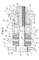
- a conical spring washer 52, a metal washer 53, and a rubber ring disc 54 are disposed between the double tube head 44 of the lock lever 40 and the sector member 33 of the throttle lever 30 in the order named when viewed from the double tube head 44.
- a rubber ring disc 54, a metal washer 53 and a conical spring washer 52 are disposed between the sector member 33 of the throttle lever 30 and the base 14a of the head member 14 in the order named when viewed from the sector member 33.
- the conical spring washers 53 form a resilient means of the throttle lever holding mechanism 50 which is disposed behind the second cam 47 (FIG.
- the rubber ring discs 54 form a friction member of the throttle lever holding mechanism 50 which is disposed between the throttle lever 30 and the lock lever 40 and is adapted to be forced against the throttle lever 30 when coaction between the first and second cams 23, 47 causes the lock lever 40 to be displaced toward the throttle lever 30 against the resiliency of the resilient mens (conical spring washers) 52.
- numeral 60 denotes a fine adjustment lever 60 attached by a screw 66 to the support lug 35 of the throttle lever 30 for achieving fine adjustment of the throttle position.
- the headed support shaft 61 has a long shank 61b extending through the conical spring washer 52, metal washer 53, rubber ring disc 54, arcuate guide hole 34 of the sector section 33, rubber ring disc 54, metal washer 53, conical spring washer 52, metal washer 53, double tube head 44 of the lock lever 40 and through-hole 23a of the cylindrical cam 23.
- a nut 62 is threaded with an externally threaded fore end portion 61c (FIG. 8) of the shank 61b of the support shaft 61, as shown in FIGS. 6-8.
- reference numeral 67 denotes a return spring acting between the throttle lever 30 and the head portion 12 to urge the throttle lever 30 toward an original unlock position.
- a tension coil spring 68 has one end connected to the hook-shaped spring retainer 43 of the lock lever 40 and the other end connected by a screw 69 to the spring retaining lug 19 on the head member 13. The spring 68 urges the lock lever 40 in an original stand-by position in which the lever portion 41 is forced against the lower oblique flat surfaces of the sleeves 17, 18, as shown in FIG. 5.
- the cylindrical first cam 23 formed integrally with the inner surface of the base 13a of the head member 13 is a fixed cam
- the second cam 47 formed at the bottom of the cylindrical extension 46a of the double tube head 44 of the lock lever 40 is a movable cam.
- the cam surface 24 formed on an end face of the cylindrical first cam 23 has an annular shape.
- the cam surface 24 has alternate ridges 24b and grooves 24a arranged in the circumferential direction of the cylindrical first cam 23.
- the grooves 24a and ridges 24b extend radially across the thickness of the cylindrical first cam 23.
- the ridges 24b each have opposite sidewalls or flanks 24c and 24e and a top 24d.
- the top 24d is flat and extends perpendicularly to an axis of the cylindrical first cam 23.
- One flank 24c which faces in the counterclockwise direction shown in FIG. 4, is beveled or sloped.
- the other flank 24e which faces toward the clockwise direction shown in FIG.
- locking direction is perpendicular to the flat top 24d and is parallel to the axis of the cylindrical first cam 23.
- the clockwise direction is the same as the direction of pivotal movement of the lock lever 40 toward a locking position. This direction is hereinafter referred to as "locking direction”.
- the cylindrical extension 46a of the double tube head 44 has an inside diameter determined to achieve a slid-fit connection between the double tube head 44 and the cylindrical first cam 23. This means that an inner peripheral surface 46b (FIG. 8) of the cylindrical extension 46a is in slide contact with an outer peripheral surface 23b of the cylindrical first cam 23.
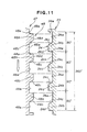
- the cam surface 48 of the movable second cam 47 which is formed on the annular end wall 44a at the bottom of the cylindrical bore 46a, has the same cam profile as the cam surface 24 of the first cam 23. More specifically, as shown in FIG. 11, the cam surface 48 has alternate ridges 48b and grooves 48a arranged in the circumferential direction of the annular end wall 44a, so that the ridges 48b of the second cam 47 can interdigitate with the ridges 24b of the first cam 23. Beveled or sloped flanks 48c of the ridges 48b face toward the locking direction (indicated by the profiled arrow in FIG. 11) which is opposite to the direction of facing of the sloped flanks 24c of the first cam 23.
- the grip portion 11 has an elongated recess 11a formed in a rear surface of the grip portion 11 along an upper member of the grip portion 11.
- the recess 11a accommodates within it the lever portion 41 of the lock lever 40 when the lock lever 40 is fully depressed, as shown in FIG. 9.
- the control cable 37 includes a control wire 37a connected at one end to the anchor pin 38 and, at the other end, to the control shaft of the throttle valve (not shown) of the engine 3 (FIG. 1).
- the control cable 37 further has an upper sheath or jacket 37b covering an upper portion of the control wire 37a, and a lower sheath or jacket 37c connected to a lower end of the upper jacket 37b and covering the remainder of the control wire 37a.
- the lower jacket 37c has a larger diameter than the upper jacket 37b.
- the upper jacket 37b has at its upper end a guide sleeve 37d of metal. The metal guide sleeve 37d is held within a retainer pocket 13h formed integrally with the base 13a of the head member 13 at a portion above the cutout portion 13f.
- the pipe 20 has a radial hole or opening 20a located near a lower opening 11b of the grip portion 11, so that the control cable 37 can be drawn out from the operation-control lever 10 through the radial opening 20a of the pipe 20 and the lower opening 11b of the grip portion 11.
- a lower end portion of the pipe 20 is drawn out from the lower opening 11b of the grip portion 11 and is connected to the support rod 5.
- the cylindrical head 32 of the throttle lever 30 is slidably fitted around the sleeves 15, 16 for pivotal movement about a common axis of the sleeves 15, 16.
- the return spring 67 is a torsion coil spring having a coiled portion 67a wound around the cylindrical head 32.
- One end 67b of the spring 67 is urged against an upper part of the peripheral wall 13b of the head member 13.
- the other end 67c of the spring 67 is anchored to a base portion of the throttle lever 31.
- the throttle lever 30 is urged to turn clockwise in FIG. 5 about the axis of the sleeves 15,16 by the resiliency of the torsion coil spring 67, so that the throttle lever 30 is normally held in the stand-by position shown in FIG. 5.
- the inner tube 45 (FIG. 6) of the double tube head 44 of the lock lever 40 is slidably fitted around the shank 61b of the support shaft 61 so that the lock lever 40 is pivotally movable about an axis of the support shaft 61.
- the lever portion 41 of the lock lever 40 project obliquely and downwardly from the elongated opening 12c of the head portion 12.
- the tension coil spring 68 acting between the hook-shaped spring retainer 43 of the lock lever 40 and the spring retaining lug 19 on the head member 13 urges the lock lever 40 to turn counterclockwise in FIG. 5 about the axis of the support shaft 61.
- the lock lever 40 is normally held in the stand-by position of FIG. 5 in which the lever portion 41 is forced against the lower oblique flat surfaces of the sleeves 17, 18.
- the support lug 35 on the sector member 33 of the throttle lever 30 is loosely received in the oblong hole 22 in the base 14a of the head member 14 with its cross-sectionally non-circular portion (including the flat surfaces 35a, 35a) projecting from an outside surface of the base 14a of the head member 14.
- the cross-sectionally non-circular portion including the flat surfaces 35 is received in a recess 60a of the fine adjustment lever 60 which is attached by the screw 66 to the support lug 35. Since the recess 60a has a non-circular cross section complementary in shape to the non-circular cross section of the support lug 35, the fine adjustment lever 60 is non-rotatable relative to the support lug 35.
- the fine adjustment lever 60 is located on the left side of the head portion 12, as shown in FIGS. 2 and 9.
- the support shaft 61 comprises a hexagon socket head cap screw having an enlarged cylindrical socket head 61a, a long shank 61b and a male screw 61c externally threaded on a fore end portion of the shank 61b.
- the socket head 61a is slidably received in the through-hole 21 of the base 14a of the head member 14 and has a hexagonal hole 61d for receiving therein the tip of a tool, such as a hexagonal bar wrench.
- a tool such as a hexagonal bar wrench
- the shank 61b of the support shaft 61 extends through the arcuate guide hole 34 of the sector member 33 of the throttle lever 30, and an axial through-hole 45a of the double tube head 45 of the lock lever 40.
- the male screw 61c of the support shaft 61 is threaded through an insert nut 70 press-fitted in the axial central hole 23a of the fixed first cam 23.
- a fore end portion of the male screw 61c projects from the insert nut 70, and the nut 62 is threaded with the projecting fore end portion of the male screw 61c to lock the support shaft 61 in position against movement relative to the head portion 12.
- the nut 62 serves as a lock nut.
- the lock nut 62 is partly received in an annular recess 13i formed in the outside surface of the base 13a of the head member 13.
- the insert nut 70 may be replaced by a sleeve (not shown).
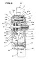
- the cam surface 24 of the fixed cylindrical first cam 23 and the cam surface 48 of the movable second cam 47 are held in pressure contact with each other with the outer peripheral surface 23 of the fixed cylindrical first cam 23 being in sliding contact with the inner peripheral surface 46b of the cylindrical extension 46a of the double tube head 44 of the lock lever 40. Since the cylindrical first cam 23 is slidably received in the cylindrical extension 46a, any foreign matter including dirt and dust is no longer possible to get into the cylindrical extension 46a. Thus, the cam surfaces 24, 48 of the first and second cams 23, 47 are completely free from contamination with dirt and dust and can operate stably and reliably over a long period of use.
- the conical spring washer 52, the washer 53 and the rubber ring disk 54 are disposed between the enlarged cylindrical head 61a of the support shaft 61 and one side surface of the sector member 33 of the throttle lever 30 in the order named when viewed from the head 61a toward the sector member 33.
- the rubber ring disk 54, the washer 53 and the conical spring washer 52 are disposed between the other side surface of the sector member 33 and one end face of the double tube head 44 of the lock lever 40 in the order named when viewed from the sector member 33 toward the double tube head 44.
- the conical spring washers 52 are disposed behind the movable second cam 47 when viewed from the fixed first cam 23 and form a resilient means for resiliently urging the cam surface 48 of the second cam 47 into pressure contact with the cam surface 24 of the first cam 23.
- the conical spring washers 52 also serve as a bias means for resiliently urging the rubber ring disks 54 against the opposite side surfaces of the sector member 33 of the throttle lever 30 when the lock lever 40 is displaced along the axis of the support shaft 61 toward the throttle lever 30 by coaction of the first and second cams 23, 47.
- the rubber ring disks 54 form a friction means adapted to be forced by the biasing means 52 against the sector member 33 of the throttle lever 30 to frictionally hold the throttle lever 30 in a desired operating position.
- the first and second cams 23, 47, the resilient means 52 and the friction member 54 jointly form the afore-mentioned throttle-lever holding mechanism 50.
- the resilient force exerted from the throttle-lever holding mechanism 50 onto the throttle lever 30 can be adjusted by turning the hexagonal socket head 61a of the support shaft 61 by use of a hexagonal bar wrench (not shown) while the lock nut 62 is kept loosened so that the support shaft 61 is displaced relative to the head member 13 in the axial direction of the support shaft 61.
- the resilient force is adjusted such that the rubber ring disks 54 are in light pressure contact with the opposite side surfaces of the sector member 33 of the throttle lever 30.
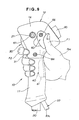
- the operation control lever unit 10 is gripped for manipulation by one hand (right hand RH, for example) of the operator M (FIG. 1).
- one hand right hand RH, for example
- an upper part of the grip portion 11 and a lower part of the head portion 12 are held in a palm of the right hand RH.
- the index finger R2 of the right hand RH is placed on the lever portion 31 of the throttle lever 30, the thumb F1 is placed on the back of the fine adjustment lever 60, and the remaining fingers are used to grasp the upper part of the grip portion 11.
- the index finger F2 is pulled to depress the throttle lever portion 31 until it reaches a desired position.
- the lever portion 41 of the lock lever 40 is depressed into the recessed portion 11a (FIG.
- the lock lever 40 turns clockwise in FIG. 10 about the support shaft 61 against the force of the return spring 68.
- the movable second cam 47 on the double tube head 44 turns about the support shaft 61 in the same direction as the lock lever 40. Accordingly, by a camming action between the respective cam surfaces 24, 48 of the first and second cams 23, 47, the rotary motion of the lock lever 40 is translated into a linear motion of the lock lever along the axis of the support shaft 61 in a direction toward the throttle lever 30.
- the lateral movement of the double tube head 44 causes the conical spring washers 52, 53 (FIG. 8) to be compressed into a substantially fully distorted flattened position between the hexagonal socket head 21a of the support shaft 61 and the washer 52.
- the conical spring washers 52, 53 With this distortion of the conical spring washers 52, 53, the rubber ring plates 54, 54 are strongly forced against the opposite surfaces of the sector member 33 of the throttler lever 30, so that the throttle lever 30 is held in a desired position against pivotal movement.
- One example of such desired position is the full-throttle position shown in FIG. 10.
- the oblong guide hole 34 of the throttle lever 30 extends arcuately about the axis of the sleeves 15, 16, the throttle lever 30 can smoothly turn about the axis of the sleeves 15, 16 while the sector member 33 is guided by sliding engagement between the guide hole 34 and the shank 61 of the support shaft 61.
- the fine adjustment lever 60 is firmly secured by the screw 66 to the distal end of the support lug 35 projecting from the sector member 33 of the throttle lever 30 through the oblong guide hole 22 to the outside of the head portion 12 of the operation-control lever unit 10.
- a ball of the thumb F1 is placed on the back of the fine adjustment lever 60, as shown in FIG. 9, then forced forwardly by the thumb F1 while a certain pressure is continuously applied from the index finger F2 to the lever portion 31 of the throttle lever 30.
- the forced forward movement of the fine adjustment lever 60 cause the throttle lever 30 to turn clockwise in FIG. 10 about the axis of the sleeves 15, 16 against a frictional force acting between the opposite surfaces of the sector member 33 and the spring biased rubber ring plates 54, 54 (FIG. 8) of the throttle-lever holding mechanism 50.
- the support lug 35 on the sector member 33 is guided by and along the arcuate oblong hole 22 formed in the base 14a (FIG. 7) of the head member 14.
- the sector member 33 slips on two opposed surfaces of the ruber ring plates 54, 54.
- the fine adjustment lever 60 is forced by the thumb F1 in the forward direction to cause the throttle lever 30 to separate from the full-throttle position of FIG. 10 and returns toward its original idling position of FIG. 5.
- the throttle valve incorporated in the carburetor of the engine 3 is operated in a direction to lower the engine speed (corresponding to power of the engine 3).
- the lock lever 40 is continuously held in its fully depressed locking position shown in FIG. 10. 10.
- the fine adjustment lever 60 is displaced in the forward direction of the head portion 12 by forcing or pushing it with the thumb F1.
- the thumb F1 when used to push the fine adjustment lever 60 can produce a greater power than when used to pull the same lever 60.
- manipulation of the fine adjustment lever 60 using the thumb F1 can be achieved with utmost ease and high reliability even though the throttle-lever holding mechanism 50 continuously operates to frictionally hold the throttle lever 30 in position against pivotal movement while the lock lever 40 is in its fully depressed position.
- the cam mechanism which forms an essential part of the throttle-lever holding mechanism 50 (FIG. 8).
- the cam mechanism is formed by the stationary cam 23 and the movable cam 47. These cams 23, 47 have respective cam surfaces 24, 48 engaged with each other.
- the cam surface 24 of the stationary cam 23 have four grooves 24a and four ridges 24b provided alternately at equal angular intervals of 90 degrees.
- the ridges 24b have the same height.
- the top surfaces 24b of the ridges 24b and the bottom surfaces of the grooves 24a are flat, parallel with each other, and perpendicular to the axis of the annular stationary cam 23.
- the flat top surfaces 24d have a predetermined width (corresponding to an extent in the circumferential direction of the cam surface 28).
- One sidewall or flank 24c of each ridge 24b is sloped, and the other flank 24e is perpendicular to the top surface 24d and the bottom surface of the groove 24a.
- the ridges 24b have a maximum width (including the width of the associated sloped flanks 24c) which is smaller than the width of the grooves 24a.
- the cam surface 48 of the movable cam 47 have four grooves 48a and four ridges 48b provided alternately at equal angular intervals of 90 degrees.
- the ridges 48b have the same height.
- the top surfaces 48b of the ridges 48b and the bottom surfaces of the grooves 48a are flat, parallel with each other, and perpendicular to the axis of the annular movable cam 47.
- the flat top surfaces 48d have substantially the same width as the flat top surfaces 24d of the ridges 24b.
- One sidewall or flank 48c of each ridge 48b is sloped, and the other flank 48e is perpendicular to the top surface 48d and the bottom surface of the groove 48a.
- a maximum width of the ridges 8b (including the width of the associated sloped flanks 48c) is substantially the same as that of the ridges 24b and is smaller than the width of the grooves 48a.
- the sloped flanks 48c of the cam surface 48 and the sloped flanks 24c of the cam surface 24 face in opposite directions so that they are slidably engaged with each other when the movable cam 24 is turned, relative to the stationary cam 23, in a direction indicated by the profiled arrow shown in FIG. 11.
- the ridges 48b of the cam surface 48 are in mesh with the ridges 24b of the cam surface 24.
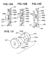
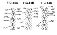
- FIG. 13 shows in comparative purposes a cam mechanism composed of two circular disc cams 123 and 147 each having on its one end face a cm surface 124, 148 including four ridges 124b, 148b formed contiguously in the circumferential direction.
- the ridges 124b, 148b have a triangular cross section and are separated by perpendicular walls 124a, 148a.
- the disc cam 123 is regarded as a stationary cam corresponding to the cam 23 (FIG. 3) formed integrally with the head member 13
- the disc cam 147 is regarded as a movable cam corresponding to the cam 48 (FIG. 3) integral with the lock lever 40.
- the cam mechanism shown in FIG. 13 operates as follows.
- the tip-to-tip engagement between the ridges 124b, 148b of the cams 123, 147 is unstable, ans so when the force exerted on the lock lever 40 changes due to a change in working condition, a change in working posture, vibrations of the engine, or external shock forces, the movable cam 148 tends to turn in the opposite direction under the bias of the conical spring washers 52, causing the ridges 148b to slide down along the ridges 124b of the stationary cam 123, as shown in FIG. 12C.
- One of the cams 23, 47 may have ridges of a triangular cross-section similar to those 124b, 148b of the cams 123, 147.
- the number of the ridges 24b, 48b should by no means be limited to four in the illustrated embodiment and may be two, three, five or more ridges may be employed.
- the stationary cam 23 formed integrally with the head member 13 of the operation-control handle 10 may be replaced with a separate cam 23 firmly secured to the head member 13.
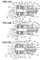
- FIGS. 15A-15C illustrate the manner in which a frictional force acting between the rubber ring discs 54 of the throttle-lever holding mechanism 50 and the sector member 55 of the throttle lever 30 is adjusted.
- the throttle-lever holding mechanism 50 In the initial condition (corresponding to the position shown in FIG. 8), the throttle-lever holding mechanism 50 is in the position (neutral position) shown in FIG. 15A.
- the support shaft 61 is rotated by the bar wrench 90 in the clockwise direction indicated by the solid-lined arrow shown in FIG. 15A.
- the support shaft 61 moves rightwards relative to the insert nut 70 and the head member 13 against the forces of the conical spring washers 52, 52, as indicated by the solid-lined arrow shown in FIG. 15B.
- the conical spring washers 52 are deflected in a somewhat flattened position and has a height B.
- the foregoing friction increasing adjustment is particularly useful when the coefficient of friction of the rubber ring discs 50 becomes small due to aging or deterioration by time. Additionally, the friction can be adjusted only by turning the support shaft 61 to move the same in an axial direction without exerting any adverse effect on another mechanism.
- the support shaft 61 When the friction between the sector member 33 and the rubber ring discs 54 is to be decreased, the support shaft 61 is rotated by the bar wrench 90 in the counterclockwise direction indicated by the broken-lined arrow shown in FIG. 15A. By virtue of threading engagement between the screw portion 61c and the insert nut 70, the support shaft 61 moves leftwards relative to the insert nut 70 and the head member 13 under the forces of the conical spring washers 52, 52, as indicated by the broken-lined arrow shown in FIG. 15C. When the support shaft 61 is displaced leftward by a distance Y from the neutral position of FIG. 15A, the conical spring washers 52 are allowed to axially expand and has a height C.
- the foregoing friction decreasing adjustment is particularly useful when the initially set friction is too large for the operator to manipulate the throttle lever 30.
- the friction increasing adjustment mentioned previously the friction decreasing operation can be achieved by merely turning the support shaft 61 and does not exert any influence on the operation of another mechanism.
- the lock nut 62 is threaded over the screw portion 61c of the support shaft 61 to lock the support shaft 61 at the desired position relative to the head portion 12 of the operation-control handle 10.
- this friction adjustment it is possible to grip the sector member 33 between the rubber ring discs 52, 52 to frictionally hold the throttle lever 30 in a desired position.
- a force required to turn the lock lever 40 to activate the throttle-lever holding mechanism 50 can be adjusted at a desired value.
- the friction on the throttle lever 40 can be easily adjusted by displacing the support shaft 61 in the axial direction by turning the support shaft 61 in such a manner that the adjusted friction is suited for the operator.
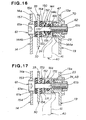
- FIG. 16 shows a modified form of the throttle-lever holding mechanism 50 according to the present invention, the modified mechanism 150 being in the state corresponding to the standby position of the lock lever 40.
- these parts which are identical to those in the embodiment shown in FIG. 8 are designated by the same reference characters, and further description thereof can, therefore, be omitted.
- the modified throttle-lever holding mechanism 150 includes a stationary cam 23 formed integrally with the head member 13, and a movable cam 47 provided at the bottom of a first axial recess 144a formed in one end face of a cylindrical head 144 of the lock lever 40.
- the axial recess 144a is slidably fitted over a peripheral surface of the stationary cam 23 which is cylindrical in shape.
- the cylindrical head 144 further has a second axial recess 144b formed in the opposite end face of the cylindrical head 144.
- a conical spring washer 152 fitted around the shank 61b of a support shaft 61 is received in the second axial recess 144b and fixed in position by a stop ring 171 attached to the support shaft 61 such that the conical spring washer 152 preloaded between the cylindrical head 144 and the stop ring 171.
- the conical spring washer 152 urges the cylindrical head 144 rightwards to keep the movable cam 48 in engagement with the stationary cam 23.
- the throttle-lever holding mechanism 150 further includes two rubber ring discs (friction members) 154, 154 fitted around the shank 61b of the support shaft 61 and disposed on opposite sides of the sector member 33 of the throttle lever 30, and two metal washers 153, 153 fitted around the shank 61b and each disposed on the outer side of one of the rubber ring discs 152, 152.
- One of the metal washers 153 is disposed between the head 61a of the support shaft 61 and one of the rubber ring discs 152, and the other metal washer 153 is disposed between the other rubber ring disc 152 and the cylindrical head 144 of the lock lever 40.
- the cylindrical head 144 further has a central annular third recess 144c facing the peripheral surface of the shank 61b.
- the annular recess 172 is filled with an oil-impregnated sponge rubber or O-ring 172.
- the metal washer 153 disposed between the sector member 33 and the cylindrical head 144 is separated by a space from the cylindrical head 144.
- the force of the conical spring washer 152 does not act on the sector member 33 of the throttle lever 30.
- the throttle lever 30 is held in the standby position of FIG. 5 by the force the return spring 67.
- the rubber ring discs 154 disposed on opposite sides of the sector member 33 is axially compressed between an under surface 61e of the head 61a of the support shaft 61 and the cylindrical head 144 of the lock lever 40.
- the sector member 33 is firmly gripped between the rubber ring discs 154, 154 with the result that the throttle lever 30 is locked in position against pivotal movement.
- the throttle lever 30 can be manipulated with a lesser force or pressure than the throttle lever operationally connected with the throttle-lever holding mechanism 50 of the first embodiment.
- the required manipulating force is at least greater than a combined force of the force of return spring 67 and the biasing force applied to the control cable 37.
- the conical spring washers 52, 152 of the throttle-lever holding mechanisms 50, 150 may be replaced with compression coil springs having a small axial length.
- the operation-control lever unit is used in the carrying bush cutter.
- the operation-control lever unit according to the present invention may be employed in other engine-powered working machines, such as shown in FIGS. 18-21.
- FIG. 18 shows a chainsaw 201 driven by an engine 203.
- the engine-driven chainsaw 201 has a grip handle 210 projecting laterally from a body 203a of the chainsaw 201, and an operation handle 210 projecting forwardly and upwardly from the engine 203.
- the grip handle 207 is gripped by a left hand LH of the operator M, and the operation handle 210 is gripped by a right hand RH of the operator M.
- the operation handle 210 is equipped with the operation-control lever unit of the present invention described above for controlling rotational speed of the engine 203.
- the chainsaw 201 has a cutting blade 206 with teeth on an endless chain projecting forwardly from the body 203a for trimming trees.
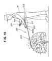
- FIG. 19 shows a chemical sprayer 301 driven by an engine 303 carried on the back of the operator M via a frame 302.
- the frame 302 also carries thereon a chemical tank 390 disposed below the engine 303.
- the chemical tank 390 has a built-in pump driven by the engine 303.
- the chemical sprayer 301 has a spray nozzle 306 attached to the top of a rigid pipe 305, and a flexible hose 304 connecting the rear end of the pipe 305 and the chemical tank 390.
- An operation handle 307 is provided on the rear end of the pipe 305 and is gripped by a right hand of the operator M.
- the operation handle 307 is equipped with the operation-control lever unit of the present invention described above.
- the pump driven by the engine 303 forces a chemical fluid to be drawn from the tank 390 and sprayed out from the spray nozzle 306 onto trees and plants.
- FIG. 20 shows a blower 401 driven by an engine 403 carried on the back of the operator M via a frame 402.
- the engine-driven blower 401 includes a blower pipe 405 having a nozzle 405a at a front end thereof, a flexible hose 404 interconnecting a rear end of the pipe 405 and a compressor 490 driven by the engine 403.
- An operation handle 410 is provided on a rear end portion of the pipe 405 and gripped by a right hand RH of the operator M.
- the operation handle 410 is equipped with the operation-control lever unit of the present invention. Pressurized air supplied from the engine-driven compressor 490 is forced out from the nozzle 405a to collect dust, leaves, trash on the roads.
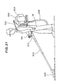
- FIG. 21 shows a vacuum dust collector 501 driven by an engine 503 carried on the back of the operator M via a frame 502.
- the vacuum dust collector 501 includes a vacuum generator 590 driven by the engine 503, a rigid pipe 505 connected to the vacuum generator 590 via a flexible hose 504, and a vacuum attachment 506 attached to a front end of the pipe 505 for collecting, by suction, dust, leaves and trash on the roads.
- An operation handle 510 is provided on a rear end portion of the pipe 505 and gripped by a right hand RH of the operator M.
- the operation handle 510 is equipped with the operation-control lever unit of the invention described above.
- An operation-control lever unit for regulating engine power of an engine-powered working machine to control operation of a working tool includes a throttle-lever holding mechanism (50) operative in response to pivotal movement of a lock lever (40) in a locking direction to frictionally hold the throttle lever (30) at a desired position.
- the throttle-lever holding mechanism (50) includes a stationary cam (23) on the head portion (12), a movable cam on the lock lever (40) and cooperating with the stationary cam (23) to displace the lock lever (40) along a support shaft (61) in a direction away from the stationary cam (23), and a resilient member (52) disposed behind the movable cam (47) and resiliently urging the movable cam (47) toward the stationary cam (23).
Landscapes
- Engineering & Computer Science (AREA)
- Chemical & Material Sciences (AREA)
- Combustion & Propulsion (AREA)
- Mechanical Engineering (AREA)
- General Engineering & Computer Science (AREA)
- Control Of Throttle Valves Provided In The Intake System Or In The Exhaust System (AREA)
- Harvester Elements (AREA)
Claims (26)
- Operations-Steuerhebeleinheit zum Regulieren der Leistung eines Motors (3) einer motorbetriebenen Arbeitsmaschine (1), um die Operation eines Arbeitswerkzeugs (6) der motorbetriebenen Arbeitsmaschine (1) zu steuern, wobei die Operations-Steuerhebeleinheit umfasst:einen Operations-Steuergriff (10) mit einem Griffabschnitt (11) und einem vergrößerten Kopfabschnitt (12) an einem Ende des Griffsabschnitts (11);einen Drosselhebel (30), der am Kopfabschnitt (12) des Griffes (10) angelenkt ist und um seine Schwenkachse innerhalb eines vorgegebenen Winkelbereiches schwenkbar ist;einen Verriegelungshebel (40), der mittels einer Unterstützungswelle (61) am Kopfabschnitt (12) angelenkt ist und um eine Achse der Unterstützungswelle (61) schwenkbar ist, wobei der Verriegelungshebel (40) gleitend längs der Achse der Unterstützungswelle (61) beweglich ist; undeinen Drosselhebel-Haltemechanismus (50; 150), der auf eine Schwenkbewegung des Verriegelungshebels (40) in Verriegelungsrichtung anspricht, um den Drosselhebel (30) mittels Reibung in einer gewünschten Position innerhalb des vorgegebenen Winkelbereiches zu halten, wobei der Drosselhebel-Haltemechanismus (50, 150) enthält:einen ersten Nocken (23), der koaxial mit der Unterstützungswelle (61) und integral mit dem Kopfabschnitt (12) des Griffes (10) ausgebildet ist,einen zweiten Nocken (47), der koaxial mit der Unterstützungswelle (61) und auf dem Verriegelungshebel (40) angeordnet ist, wobei der zweite Nocken (47) mit dem ersten Nocken (23) so zusammenwirkt, dass der Verriegelungshebel (40) längs der Unterstützungswelle (61) in einer ersten Richtung vom ersten Nocken (23) weg verschoben wird; undein Federmittel (52; 152), das bei Betrachtung vom ersten Nocken (23) her hinter dem zweiten Nocken (47) angeordnet ist, und das den zweiten Nocken (47) elastisch in Richtung zum ersten Nocken (23) drängt.
- Operations-Steuerhebeleinheit nach Anspruch 1, bei der einer (47) der ersten und zweiten Nocken (23, 47) einen integralen rohrförmigen Abschnitt (46) koaxial mit der Unterstützungswelle (61) und in Richtung zum anderen Nocken (23) hervorstehend aufweist, wobei der andere Nocken (23) eine Außenumfangsoberfläche (23b) aufweist, die gleitend im rohrförmigen Abschnitt (46) aufgenommen ist.
- Operations-Steuerhebeleinheit nach Anspruch 1, bei der der erste Nocken (23) eine ringförmige Nockenoberfläche (24) mit wenigstens einer radialen Rippe (24b) aufweist und der zweite Nocken (47) eine ringförmige Nockenoberfläche (48) mit wenigstens einer radialen Rippe (48b) aufweist, die mit der Rippe (24) der Nockenoberfläche (24) des ersten Nockens (47) in Eingriff ist.
- Operations-Steuerhebeleinheit nach Anspruch 3, bei der wenigstens eine Rippe (24b) des ersten Nockens (23) und die Rippe (48b) des zweiten Nockens (47) eine flache obere Oberfläche (24d, 48d) aufweisen.
- Operations-Steuerhebeleinheit nach Anspruch 4, bei der die flache obere Oberfläche (24d, 48d) senkrecht zur Achse der Unterstützungswelle (61) verläuft.
- Operations-Steuerhebeleinheit nach Anspruch 5, bei der die wenigstens eine Rippe (24b, 48b) eine im wesentlichen trapezförmige Querschnittsform aufweist.
- Operations-Steuerhebeleinheit nach Anspruch 3, bei der mehrere Rippen (24b) am ersten Nocken (23) vorhanden sind, wobei die mehreren Rippen (24b) in gleichmäßigen Intervallen in Umfangsrichtung der ringförmigen Nockenoberfläche (24b) des ersten Nockens (23) angeordnet sind, und wobei mehrere Rippen (48b) am zweiten Nocken (47) vorhanden sind, wobei die mehreren Rippen (48b) des zweiten Nockens (47) in gleichmäßigen Intervallen in Umfangsrichtung der ringförmigen Nockenoberfläche (48) des zweiten Nockens (47) angeordnet sind.
- Operations-Steuerhebeleinheit nach Anspruch 7, bei der wenigstens die Rippen (24b) des ersten Nockens (23) und/oder die Rippen (48b) des zweiten Nockens (47) jeweils eine flache obere Oberfläche (24d, 48d) aufweisen.
- Operations-Steuerhebeleinheit nach Anspruch 8, bei der die flache obere Oberfläche (24d, 48d) senkrecht zur Achse der Unterstützungswelle (61) verläuft.
- Operations-Steuerhebeleinheit nach Anspruch 9, bei der die Rippen (24b) des ersten Nockens (23) oder die Rippen (48b) des zweiten Nockens (47) eine im wesentlichen trapezförmige Querschnittsform aufweisen.
- Operations-Steuerhebeleinheit nach Anspruch 1, bei der der Drosselhebel-Haltemechanismus (50, 150) femer ein Reibungselement (54; 154) enthält, das zwischen dem Drosselhebel (30) und dem Verriegelungshebel (40) angeordnet ist und gegen den Drosselhebel (30) gedrückt wird, wenn ein Zusammenwirken zwischen den ersten und zweiten Nocken (23, 47) den Verriegelungshebel (40) gegen die Federkraft des Federmittels (52; 152) in der ersten Richtung verschiebt.
- Operations-Steuerhebeleinheit nach Anspruch 11, bei der der Drosselhebel-Haltemechanismus (50, 150) ferner ein zweites Reibungselement (54; 154) enthält, das dem zuerst erwähnten Reibungselement (54; 154) gegenüberliegend angeordnet ist, wobei der Drosselhebel (30) dazwischen angeordnet ist, und wobei das zuerst erwähnte Reibungselement (54; 154) und das zweite Reibungselement (54, 154) zusammenwirken, um dazwischen den Drosselhebel (30) zu greifen, wenn der Verriegelungshebel (40) in der ersten Richtung verschoben wird.
- Operations-Steuerhebeleinheit nach Anspruch 12, bei der das zuerst erwähnte Reibungselement (54; 154) und das zweite Reibungselement (54; 154) Gummiringscheiben sind, die auf der Unterstützungswelle (61) montiert sind.
- Operations-Steuerhebeleinheit nach Anspruch 11, bei der das Federmittel (52) zwischen dem Verriegelungshebel (40) und dem Reibungselement (54) angeordnet ist und den Verriegelungshebel in einer zweiten Richtung drängt, um den zweiten Nocken (47) in Richtung zum ersten Nocken (23) zu bewegen, und das Reibungselement (54) in Kontakt mit dem Drosselhebel (30) drängt.
- Operations-Steuerhebeleinheit nach Anspruch 14, bei der das Federmittel (52) eine konische Federbeilagscheibe ist, die auf der Unterstützungswelle (61) montiert ist.
- Operations-Steuerhebeleinheit nach Anspruch 12, bei der das Federmittel (52) ein erstes Federelement (52), das zwischen dem Verriegelungshebel (40) und dem zuerst erwähnten Reibungselement (54) angeordnet ist, und ein zweites Federelement (52), das zwischen dem zweiten Reibungselement (54) und einem Abschnitt der Unterstützungswelle (61) angeordnet ist, enthält, wobei das erste Federelement (52) den Verriegelungshebel in einer zweiten Richtung drängt, um den zweiten Nocken (47) in Richtung zum ersten Nocken (23) zu bewegen, und das zuerst erwähnte Reibungselement (54) in Kontakt mit dem Drosselhebel (30) drängt, und wobei das zweite Federelement (52) das zweite Reibungselement (54) in Kontakt mit dem Drosselhebel (30) drängt.
- Operations-Steuerhebeleinheit nach Anspruch 16, bei der die ersten und zweiten Federelemente (52, 52) konische Federbeilagscheiben sind, die auf der Unterstützungswelle (61) montiert sind.
- Operations-Steuerhebeleinheit nach Anspruch 11, bei der das erste Federmittel (152) zwischen dem Verriegelungshebel (40) und dem ersten Reibungselement (54) angeordnet ist und den Verriegelungshebel in einer zweiten Richtung drängt, um den zweiten Nocken (47) in Richtung zum ersten Nocken (23) zu bewegen, wobei das Federmittel (152) vom Reibungselement (154) operativ getrennt ist.
- Operations-Steuerhebeleinheit nach Anspruch 18, bei der der Drosselhebel-Haltemechanismus (150) ferner ein zweites Reibungselement (154) enthält, das dem zuerst erwähnten Reibungselement (154) gegenüberliegend angeordnet ist, wobei dazwischen der Drosselhebel (30) angeordnet ist, und wobei das zuerst erwähnte Reibungselement (154) und das zweite Reibungselement (154) zusammenwirken, um dazwischen den Drosselhebel (30) zu greifen, wenn der Verriegelungshebel (40) in der ersten Richtung verschoben wird.
- Operations-Steuerhebeleinheit nach Anspruch 19, bei der das zuerst erwähnte Reibungselement (154) und das zweite Reibungselement (154) Gummiringscheiben sind, die auf der Unterstützungswelle (61) montiert sind.
- Operations-Steuerhebeleinheit nach Anspruch 18, bei der das Federmittel (152) eine konische Federbeilagscheibe ist, die auf der Unterstützungswelle (61) montiert ist.
- Operations-Steuerhebeleinheit nach Anspruch 11, bei der das Federmittel (52; 152) zwischen dem Verriegelungshebel und dem Reibungselement (54; 154) angeordnet ist, wobei der Drosselhebel-Haltemechanismus (50, 150) femer eine Reibungseinstellvorrichtung (61) enthält, um eine Vorbelastung auf das Federmittel (52; 152) zu variieren, um eine Reibungskraft einzustellen, die zwischen dem Drosselhebel (30) und dem Reibungselement (54; 154) wirkt.
- Operations-Steuerhebeleinheit nach Anspruch 22, bei der die Unterstützungswelle (61) eine Schraube ist, die einen Kopf (61a), der gleitend in einem ersten Abschnitt (21) des Kopfabschnitts (12) des Griffes (10) geführt ist, sowie einen Schaft (61b) aufweist, der einen Gewindeabschnitt (61c) enthält, der mit einem zweiten Abschnitt (70) des Kopfabschnitts (12) verschraubt ist, wobei das Federmittel (52, 152), das Reibungselement (54, 154) und der Drosselhebel (30) zwischen dem Kopf (61a) der Schraube (61) und dem Verriegelungshebel (40) angeordnet sind, und wobei die Schraube (61) die Reibungseinstellvorrichtung bildet.
- Operations-Steuerhebeleinheit nach Anspruch 22, bei der der Drosselhebel-Haltemechanismus (50, 150) femer ein zweites Reibungselement (54; 154) enthält, das zwischen dem Drosselhebel (30) und dem Kopf (61a) der Schraube (61) angeordnet ist, wobei das zuerst erwähnte Reibungselement (54; 154) und das zweite Reibungselement (54; 154) zusammenwirken, um dazwischen den Drosselhebel (30) zu greifen, wenn der Verriegelungshebel (40) in der ersten Richtung verschoben wird.
- Operations-Steuerhebeleinheit nach Anspruch 23, bei der die Schraube eine Innensechskantschraube (61) ist.
- Operations-Steuerhebeleinheit nach Anspruch 23, bei der die Reibungseinstellvorrichtung femer eine Verriegelungsmutter (72) enthält, die mit dem Gewindeabschnitt (61c) der Schraube (61) verschraubt ist, um die Schraube (61) in einer Position gegen eine Bewegung relativ zum Kopfabschnitt (12) zu verriegeln.
Applications Claiming Priority (6)
| Application Number | Priority Date | Filing Date | Title |
|---|---|---|---|
| JP18123598 | 1998-06-26 | ||
| JP18123398 | 1998-06-26 | ||
| JP18123598A JP3489809B2 (ja) | 1998-06-26 | 1998-06-26 | 作業機の操作レバー装置 |
| JP18123398A JP3489808B2 (ja) | 1998-06-26 | 1998-06-26 | 作業機の操作レバー装置 |
| JP18530798A JP3411504B2 (ja) | 1998-06-30 | 1998-06-30 | 作業機の操作レバー装置 |
| JP18530798 | 1998-06-30 |
Publications (3)
| Publication Number | Publication Date |
|---|---|
| EP0967374A2 EP0967374A2 (de) | 1999-12-29 |
| EP0967374A3 EP0967374A3 (de) | 2000-10-04 |
| EP0967374B1 true EP0967374B1 (de) | 2004-03-03 |
Family
ID=27324975
Family Applications (1)
| Application Number | Title | Priority Date | Filing Date |
|---|---|---|---|
| EP99112280A Expired - Lifetime EP0967374B1 (de) | 1998-06-26 | 1999-06-25 | Bedienungshandgriff für ein motorgetriebenes Gerät |
Country Status (3)
| Country | Link |
|---|---|
| US (1) | US6209412B1 (de) |
| EP (1) | EP0967374B1 (de) |
| DE (1) | DE69915176T2 (de) |
Families Citing this family (14)
| Publication number | Priority date | Publication date | Assignee | Title |
|---|---|---|---|---|
| DE20006073U1 (de) * | 2000-04-01 | 2000-07-06 | Andreas Stihl AG & Co., 71336 Waiblingen | Handgeführtes Arbeitsgerät mit einem Antriebsmotor |
| JP4027043B2 (ja) * | 2001-01-15 | 2007-12-26 | 本田技研工業株式会社 | 刈払機の操作レバー |
| DE10332242A1 (de) * | 2003-07-16 | 2005-02-03 | Andreas Stihl Ag & Co. Kg | Handgeführtes Arbeitsgerät |
| SE0302439D0 (sv) * | 2003-09-12 | 2003-09-12 | Electrolux Ab | Throttle control device for a hand held tool |
| US20070128956A1 (en) * | 2005-02-22 | 2007-06-07 | Blair Charles S | Torsional control boat throttle system |
| US20090229567A1 (en) * | 2006-05-17 | 2009-09-17 | Garth Edgar Taylor | safety lockout device |
| CA2557949A1 (en) * | 2006-08-22 | 2008-02-22 | Michel Lachance | Safety throttle control apparatus |
| US20090221196A1 (en) * | 2008-02-29 | 2009-09-03 | Blair Charles S | Torsional control boat throttle system |
| US8584550B1 (en) * | 2009-05-18 | 2013-11-19 | John L. Calendrille, Jr. | Shift lever arrangement for a bicycle |
| JP2013537592A (ja) * | 2010-06-28 | 2013-10-03 | ハスクバーナ・アーベー | アクセル装置 |
| WO2012001732A1 (en) * | 2010-06-28 | 2012-01-05 | Husqvarna Zenoah Co., Ltd. | Accelerator |
| DE112010005799T5 (de) * | 2010-08-11 | 2013-07-04 | Bosch Power Tools (China) Co., Ltd. | Elektrohandwerkzeug mit Schnellbremsanordnung |
| JP6360658B2 (ja) * | 2013-03-29 | 2018-07-18 | 株式会社マキタ | チェンソーのチェーン張力調整装置 |
| CN119668357B (zh) * | 2024-12-09 | 2025-07-18 | 山东立派机械集团有限公司 | 一种装载机操作控制手柄 |
Family Cites Families (12)
| Publication number | Priority date | Publication date | Assignee | Title |
|---|---|---|---|---|
| JPS6043716B2 (ja) | 1976-09-30 | 1985-09-30 | 松下電器産業株式会社 | 直交変換符号化回路 |
| JPS586794B2 (ja) | 1978-07-31 | 1983-02-07 | 日本電気ホームエレクトロニクス株式会社 | 部分ニツケル層の形成方法 |
| JPS6041539A (ja) | 1983-08-16 | 1985-03-05 | Sumitomo Electric Ind Ltd | 堆積物自動除去装置 |
| JPS6314035A (ja) | 1986-06-27 | 1988-01-21 | Matsushita Electric Ind Co Ltd | 凍結防止装置 |
| JP3237997B2 (ja) * | 1994-04-25 | 2001-12-10 | 株式会社共立 | 内燃機関用スロットルの安全装置 |
| JPH08126683A (ja) * | 1994-10-31 | 1996-05-21 | Fujisawa Pharmaceut Co Ltd | 輸液用容器 |
| JP3305157B2 (ja) * | 1995-05-02 | 2002-07-22 | 株式会社共立 | ハンドレバー装置 |
| JPH0914004A (ja) * | 1995-06-23 | 1997-01-14 | Kioritz Corp | ハンドレバー装置 |
| JPH0914003A (ja) * | 1995-06-23 | 1997-01-14 | Kioritz Corp | ハンドレバー装置 |
| JP3529199B2 (ja) * | 1995-08-04 | 2004-05-24 | 株式会社共立 | ハンドレバー装置 |
| DE19621729B4 (de) * | 1996-05-29 | 2007-10-25 | Starting Industrial Co., Ltd. | Gashebeleinrichtung für einen Motor |
| JP3850954B2 (ja) * | 1997-06-27 | 2006-11-29 | 本田技研工業株式会社 | 作業機の操作レバー装置 |
-
1999
- 1999-06-25 US US09/344,229 patent/US6209412B1/en not_active Expired - Fee Related
- 1999-06-25 DE DE69915176T patent/DE69915176T2/de not_active Expired - Lifetime
- 1999-06-25 EP EP99112280A patent/EP0967374B1/de not_active Expired - Lifetime
Also Published As
| Publication number | Publication date |
|---|---|
| DE69915176D1 (de) | 2004-04-08 |
| EP0967374A3 (de) | 2000-10-04 |
| EP0967374A2 (de) | 1999-12-29 |
| US6209412B1 (en) | 2001-04-03 |
| DE69915176T2 (de) | 2004-07-29 |
Similar Documents
| Publication | Publication Date | Title |
|---|---|---|
| EP0967374B1 (de) | Bedienungshandgriff für ein motorgetriebenes Gerät | |
| US6176016B1 (en) | Operation control lever unit for engine-powered working machine | |
| US6349473B1 (en) | Utility knife | |
| US4308769A (en) | Reversing ratcheting wrench | |
| US5007313A (en) | Pliers | |
| US5758546A (en) | Hand lever device | |
| US6848344B2 (en) | Articulating wrench assembly | |
| US5078023A (en) | Thumb-operated throttle control | |
| US4019402A (en) | Motorcycle throttle twist-grip control | |
| US11351660B2 (en) | Reversible ratchet wrench | |
| US5685271A (en) | Hand lever device | |
| EP0887531B1 (de) | Schalthebelvorrichtung für motorgetriebene Maschinen | |
| JP3993925B2 (ja) | 刈取作業機用ハンドレバー装置 | |
| US6196082B1 (en) | Hand lever device | |
| US5664543A (en) | Hand lever device | |
| JP2001200735A (ja) | 作業機のスロットル調整装置 | |
| US4580468A (en) | Pipe wrench | |
| JP3489809B2 (ja) | 作業機の操作レバー装置 | |
| JP4094786B2 (ja) | ハンドレバー装置 | |
| JP4485986B2 (ja) | ハンドレバー装置 | |
| JP2000014224A (ja) | 作業機の操作レバー装置 | |
| JP3946382B2 (ja) | ハンドレバー装置 | |
| JP3483669B2 (ja) | ハンドレバー装置 | |
| JP4547059B2 (ja) | ハンドレバー装置 | |
| JP2000004636A (ja) | 作業機の操作レバー装置 |
Legal Events
| Date | Code | Title | Description |
|---|---|---|---|
| PUAI | Public reference made under article 153(3) epc to a published international application that has entered the european phase |
Free format text: ORIGINAL CODE: 0009012 |
|
| AK | Designated contracting states |
Kind code of ref document: A2 Designated state(s): DE FR GB |
|
| AX | Request for extension of the european patent |
Free format text: AL;LT;LV;MK;RO;SI |
|
| PUAL | Search report despatched |
Free format text: ORIGINAL CODE: 0009013 |
|
| AK | Designated contracting states |
Kind code of ref document: A3 Designated state(s): AT BE CH CY DE DK ES FI FR GB GR IE IT LI LU MC NL PT SE |
|
| AX | Request for extension of the european patent |
Free format text: AL;LT;LV;MK;RO;SI |
|
| RIC1 | Information provided on ipc code assigned before grant |
Free format text: 7F 02B 63/02 A, 7F 02D 11/02 B |
|
| 17P | Request for examination filed |
Effective date: 20001121 |
|
| AKX | Designation fees paid |
Free format text: DE FR GB |
|
| GRAP | Despatch of communication of intention to grant a patent |
Free format text: ORIGINAL CODE: EPIDOSNIGR1 |
|
| GRAS | Grant fee paid |
Free format text: ORIGINAL CODE: EPIDOSNIGR3 |
|
| GRAA | (expected) grant |
Free format text: ORIGINAL CODE: 0009210 |
|
| AK | Designated contracting states |
Kind code of ref document: B1 Designated state(s): DE FR GB |
|
| REG | Reference to a national code |
Ref country code: GB Ref legal event code: FG4D |
|
| REF | Corresponds to: |
Ref document number: 69915176 Country of ref document: DE Date of ref document: 20040408 Kind code of ref document: P |
|
| ET | Fr: translation filed | ||
| PLBE | No opposition filed within time limit |
Free format text: ORIGINAL CODE: 0009261 |
|
| STAA | Information on the status of an ep patent application or granted ep patent |
Free format text: STATUS: NO OPPOSITION FILED WITHIN TIME LIMIT |
|
| 26N | No opposition filed |
Effective date: 20041206 |
|
| PGFP | Annual fee paid to national office [announced via postgrant information from national office to epo] |
Ref country code: GB Payment date: 20130619 Year of fee payment: 15 Ref country code: DE Payment date: 20130619 Year of fee payment: 15 |
|
| PGFP | Annual fee paid to national office [announced via postgrant information from national office to epo] |
Ref country code: FR Payment date: 20130624 Year of fee payment: 15 |
|
| REG | Reference to a national code |
Ref country code: DE Ref legal event code: R119 Ref document number: 69915176 Country of ref document: DE |
|
| GBPC | Gb: european patent ceased through non-payment of renewal fee |
Effective date: 20140625 |
|
| REG | Reference to a national code |
Ref country code: DE Ref legal event code: R119 Ref document number: 69915176 Country of ref document: DE Effective date: 20150101 |
|
| REG | Reference to a national code |
Ref country code: FR Ref legal event code: ST Effective date: 20150227 |
|
| PG25 | Lapsed in a contracting state [announced via postgrant information from national office to epo] |
Ref country code: DE Free format text: LAPSE BECAUSE OF NON-PAYMENT OF DUE FEES Effective date: 20150101 |
|
| PG25 | Lapsed in a contracting state [announced via postgrant information from national office to epo] |
Ref country code: FR Free format text: LAPSE BECAUSE OF NON-PAYMENT OF DUE FEES Effective date: 20140630 Ref country code: GB Free format text: LAPSE BECAUSE OF NON-PAYMENT OF DUE FEES Effective date: 20140625 |