EP0967374B1 - Operation-control lever unit for engine-powered working machine - Google Patents
Operation-control lever unit for engine-powered working machine Download PDFInfo
- Publication number
- EP0967374B1 EP0967374B1 EP99112280A EP99112280A EP0967374B1 EP 0967374 B1 EP0967374 B1 EP 0967374B1 EP 99112280 A EP99112280 A EP 99112280A EP 99112280 A EP99112280 A EP 99112280A EP 0967374 B1 EP0967374 B1 EP 0967374B1
- Authority
- EP
- European Patent Office
- Prior art keywords
- cam
- lever
- throttle
- friction member
- unit according
- Prior art date
- Legal status (The legal status is an assumption and is not a legal conclusion. Google has not performed a legal analysis and makes no representation as to the accuracy of the status listed.)
- Expired - Lifetime
Links
Images


Classifications
-
- F—MECHANICAL ENGINEERING; LIGHTING; HEATING; WEAPONS; BLASTING
- F02—COMBUSTION ENGINES; HOT-GAS OR COMBUSTION-PRODUCT ENGINE PLANTS
- F02B—INTERNAL-COMBUSTION PISTON ENGINES; COMBUSTION ENGINES IN GENERAL
- F02B63/00—Adaptations of engines for driving pumps, hand-held tools or electric generators; Portable combinations of engines with engine-driven devices
- F02B63/02—Adaptations of engines for driving pumps, hand-held tools or electric generators; Portable combinations of engines with engine-driven devices for hand-held tools
-
- Y—GENERAL TAGGING OF NEW TECHNOLOGICAL DEVELOPMENTS; GENERAL TAGGING OF CROSS-SECTIONAL TECHNOLOGIES SPANNING OVER SEVERAL SECTIONS OF THE IPC; TECHNICAL SUBJECTS COVERED BY FORMER USPC CROSS-REFERENCE ART COLLECTIONS [XRACs] AND DIGESTS
- Y10—TECHNICAL SUBJECTS COVERED BY FORMER USPC
- Y10T—TECHNICAL SUBJECTS COVERED BY FORMER US CLASSIFICATION
- Y10T74/00—Machine element or mechanism
- Y10T74/20—Control lever and linkage systems
- Y10T74/20396—Hand operated
- Y10T74/20402—Flexible transmitter [e.g., Bowden cable]
- Y10T74/2042—Flexible transmitter [e.g., Bowden cable] and hand operator
- Y10T74/20438—Single rotatable lever [e.g., for bicycle brake or derailleur]
-
- Y—GENERAL TAGGING OF NEW TECHNOLOGICAL DEVELOPMENTS; GENERAL TAGGING OF CROSS-SECTIONAL TECHNOLOGIES SPANNING OVER SEVERAL SECTIONS OF THE IPC; TECHNICAL SUBJECTS COVERED BY FORMER USPC CROSS-REFERENCE ART COLLECTIONS [XRACs] AND DIGESTS
- Y10—TECHNICAL SUBJECTS COVERED BY FORMER USPC
- Y10T—TECHNICAL SUBJECTS COVERED BY FORMER US CLASSIFICATION
- Y10T74/00—Machine element or mechanism
- Y10T74/20—Control lever and linkage systems
- Y10T74/20576—Elements
- Y10T74/20636—Detents
- Y10T74/2066—Friction
Definitions
- the present invention relates to an operation-control lever unit for regulating power of an engine of an engine-powered working machine to control operation of a working tool of the engine-powered working machine.
- the engine-powered working machine may include a carrying bush cutter, a chemical sprayer, a vacuum dust collector and so on.
- a carrying bush cutter having a circular cutter driven for rotation by an engine carried on the back of an operator is known from Japanese Utility Model Publication No. (SHO) 63-14035.
- the circular cutter is attached to one end of a hand-operating rod.
- the rod is provided with an operation handle near the other end thereof.
- the operator swings the rod up and down and right and left while gripping the operation handle. With this swinging operation, bushes are cut or removed by the rotating circular cutter.
- a lock mechanism is associated with a throttle lever to temporarily lock the throttle lever in a desired position, so that the work load on the operator can be reduced.
- Typical examples of the prior improvements are disclosed in Japanese Utility Model Publication Nos. (SHO) 53-42661 and (SHO) 55-21536, Japanese Utility Model Laid-open Publication No. (SHO) 60-41539, and Japanese Patent Laid-open Publication No. (HEI) 8-303263.
- the throttle lever is displaced to a predetermined operating position, then locked in this operating position by activating the lock mechanism.
- the lock mechanism is released at need.
- the operation lever unit disclosed in Japanese Utility Model Publication Nos. (SHO) 55-21536 includes a throttle adjustment lever and a throttle release lever provided side by side on the operating handle.
- the operation lever unit is complicated in construction, requires an increased number of structural components, and is uneasy to manipulate.
- a frictional force acting on the throttle lever to lock the same lever in position against pivotal movement tends to decrease and eventually allows the throttle lever to move from the locked position.
- the throttle lever may sometimes return to its original position when the operation lever unit is subjected to vibration.
- the operation lever unit has no means to adjust the frictional force acting on the throttle lever.
- the operation lever unit disclosed in Japanese Utility Model Publication No. (SHO) 53-42661 includes a locking pawl pivotally mounted between the pivot axis of a throttle lever and the pivot axis of a lock lever for operatively interlocking the two levers. Because of the presence of the locking pawl, the operating lever unit is complicated in construction and requires an increased number of structural components.
- the present invention is conceived to solve the foregoing problems associated with the prior art.
- a more specific object of the present invention is to provide a operation-control lever unit for an engine-powered working machine, which includes a throttle lever, a lock lever and a throttle-lever holding mechanism of simple construction having a relatively small number of components.
- Another object of the present invention is to provide an operation-control lever unit for an engine-powered working machine, which is simple in construction and is capable of reliably locking a throttle lever in a desired position to regulate output power of an engine of the engine-powered working machine while keeping good manipulability of a lock lever disposed close to the throttle lever.
- the throttle-lever holding mechanism includes a first cam coaxial with the support shaft and formed integrally with the head portion of the handle, a second cam coaxial with the support shaft and provided on the lock lever, the second cam being co-active with the first cam to displace the lock lever along the support shaft in a first direction away from the first cam, and a resilient means disposed behind the second cam when viewed from the first cam and resiliently urging the second cam toward the first cam.
- the throttle-lever holding mechanism is relatively simple in construction and has a small number of structural components.
- one of the first and second cams has an integral tubular portion coaxial with the support shaft and projecting toward the other cam.
- the other cam has an outer peripheral surface slidably received in the tubular portion.
- the first and second cams each have an annular cam surface having at least one radial ridge. At least one of the ridge of the first cam and the ridge of the second cam has a flat top surface. With this flat top surface, the throttle lever can be stably held in a locked position even when the lock lever is pivoted to some extent.
- the flat top surface is preferably perpendicular to the axis of the support shaft.
- the ridge may have a generally trapezoidal cross-sectional shape.
- the throttle-lever holding mechanism further includes a friction member disposed between the throttle lever and the lock lever and forced against the throttle lever when coaction between the first and second cams displaces the lock lever in the first direction against the resiliency of the resilient means.
- the throttle-lever holding mechanism may also include a second friction member disposed opposite to the first-mentioned friction member with the throttle lever disposed therebetween. The first-mentioned friction member and the second friction member cooperate to grip the throttle lever therebetween when the lock lever is displaced in the first direction.
- the first-mentioned friction member and the second friction member are preferably rubber ring discs mounted on the support shaft.
- the resilient means is disposed between the lock lever and the friction member and urges the lock lever in a second direction to move the second cam toward the first cam and also urges the friction member into contact with the throttle lever.
- the resilient means is preferably a conical spring washer mounted on the support shaft.
- the resilient means may include a first resilient member disposed between the lock lever and the first-mentioned friction member, and a second resilient member disposed between the second friction member and a portion of the support shaft.
- the first resilient member urges the lock lever in a second direction to move the second cam toward the first cam and also urges the first-mentioned friction member into contact with the throttle lever.
- the second resilient member urges the second friction member into contact with the throttle lever.
- the resilient means may be disposed between the lock lever and the friction member urge the lock lever in a second direction to move the second cam toward the first cam.
- the resilient means is operatively separated from the friction member.
- the resilient means is disposed between the lock lever and the friction member, and the throttle-lever holding mechanism further includes a friction adjustment device for varying a preloading on the resilient means to adjust a frictional force acting between the throttle lever and the friction member.
- the support shaft is a screw having a head slidably guided in a first portion of the head portion of the handle and a shank including a screw portion threaded with a second portion of the head portion.
- the resilient means, the friction member and the throttle lever are disposed between the head of the screw and the lock lever.
- the screw forms the friction adjustment device. By turning the screw, the screw moves in an axial direction.
- the screw is preferably a hexagonal socket head cap screw.
- the friction adjustment device may further include a lock nut threaded with the screw portion of the screw to lock the screw in position against movement relative to the head portion.
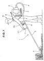
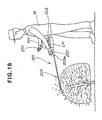
- FIG. 1 there is shown a carrying bush cutter 1 as it is used in a bush-removing work as an engine-powered working machine in which an operation-control lever unit according to the present invention is incorporated.
- the carrying bush cutter 1 includes a frame 2, a power unit such as a gasoline engine 3 mounted on the frame 2, a flexible tube 4 connected at one end to a power output portion of the engine 3, an elongated rigid hollow support rod 5 having one end (proximal end) connected to the other end of the flexible tube 4, and a circular cutter (working tool) 6 rotatably attached to the other end (distal end) of the support rod 5.
- the circular cuter 6 is connected in driven relation to the engine 3 via a flexible power transmission shaft (not shown) extending through the support rod 6 and the flexible tube 4. Thus, the circular cutter 6 is driven in rotation by output power of the engine 3.
- a grip handle 7 and an operation-control handle 10 are provided on a proximal end portion of the support rod 7.
- the operation-control handle 10 is disposed behind the grip handle 7 when viewed from the distal end of the support rod 5.
- the grip handle 7 and the operation-control handle 10 extend orthogonally from an upper surface of the support rod 3.
- the frame 2 has a pair of belts or straps (one being shown in FIG. 1) for enabling the operator M to carry the engine 3 on its back, with a cushioning pad 9 disposed between the back of the operator M and the frame 2.
- the support rod 5 is held on, for example, the right side of a body of the operator M, with the grip handle 7 and the operation-control handle 10 being gripped by the left hand LH and the right hand RH of the operator M, respectively.
- the support rod 5 is swung right and left and up and down about its proximal end so that bushes are cut or removed by the rotating circular cutter 6.
- the left hand LH of the operator M is used essentially for gripping the grip handle 7 and moving the support rod 5 right and left and up and down.
- the right hand RH is used for gripping the operation-control handle 10 and performing throttle adjustment to regulate output power of the engine 3.
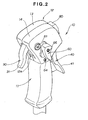
- the operation-control handle 10 constitutes a main part of the operation-control lever unit of the present invention.
- the operation-control handle 10 is in the form of the grip of a gun and includes a tubular grip portion 11 secured at a lower end to the support rod 5 via a bracket (not shown), and an enlarged head portion 12 secured to an upper end of the grip portion 11.
- the head portion 12 is a hollow member of split structure consisting of left and right head halves or members 13, 14 joined together back to back to form a hollow interior space or pocket in the head portion 12.
- the head portion 12 has an elongate hole or opening 12a formed in a front wall thereof.
- a throttle lever 30 and a lock lever 4C of the operation-control lever unit are pivotally mounted to the head portion 12 within the pocket.
- the throttle lever 30 has a trigger-like lever portion 31 projecting forwardly and downwardly from the elongate opening 12a in the front wall of the head portion 12.
- the lock lever 40 has an actuating lever portion 41 projecting rearwardly and downwardly from an elongate hole or opening 12c (FIG. 5) formed in a rear wall of the head portion 12.
- An engine start switch 80 for starting and stopping the engine 3 (FIG. 1) is provided on the rear wall of the head portion 12 at a position above the opening 12c (FIG. 5). Additionally, a secondary throttle adjustment lever 60 is provided on one side (left side in the illustrated embodiment) of the head portion 12 for achieving fine adjustment of the position of the throttle lever 30.
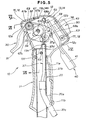
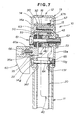
- FIG. 3 shows in perspective the general arrangement of the operation-control lever unit of the present invention.
- the head members 13, 14 have a generally pentagonal dish-like form and each include a planar base 13a, 14a and a peripheral wall 13b, 14b integral with a peripheral edge of the base 13a, 14a and extending perpendicularly to the base 13a, 14a.
- the peripheral wall 13b has four cutout portions 13c, 13d, 13e and 13f formed in consecutive four sides of the pentagonal head member 13.
- the peripheral wall 14b has four cutout portions 14d, 14e (two cutout portions corresponding in position to the cutout portions 13c, 13f being not shown) formed in consecutive four sides of the pentagonal head member 14.
- the cutout portion 13c of the peripheral wall 13b and the corresponding unillustrated cutout portion of the peripheral wall 14b jointly form the above-mentioned elongate opening 12a (FIGS. 1 and 5).
- the cutout portions 13d, 14d jointly form an elongated hole or opening 12b (FIG. 5) from which the engine start switch 60 projects outwardly.
- the cutout portions 13e, 14e jointly form the above-mentioned elongated opening 12c (FIG. 5) which allows pivotal movement of the lock lever 40.
- the head member 13 has an integral cylindrical sleeve 15 projecting perpendicularly from an inside surface of the planar base 13a.
- the sleeve 15 is located near a front end of the head portion 12.
- the head member 14 also has an integral cylindrical sleeve 16 projecting perpendicularly from an inside surface of the planar base 14a.
- the sleeve 16 is aligned with the sleeve 15.
- the sleeve 15 of the head member 13 has a through-hole, while the sleeve 16 of the head member 14 has an internally threaded blind hole closed at one end by the base 14a.
- the head members 13, 14 further have a pair of aligned cylindrical sleeves 17, 18 projecting perpendicularly from respective inside surfaces of the planar bases 13a, 14a at a position located near a rear end of the head members 13, 14.
- the sleeve 17 has a through-hole, while the sleeve 18 has an internally threaded blind hole closed by the base 14a.
- the sleeve 18 is longer than the sleeve 17.
- Respective outer peripheral surfaces of the sleeves 17, 18 are cut or removed at diametrically opposite portions thereof so as to define a pair of parallel diametrically opposite flat surfaces extending obliquely to an axis of the grip portion 11 (FIG. 2).
- An internally threaded hollow cylindrical spring retaining lug 19 projects perpendicularly from the inside surface of the base 13a of the head member 13.
- the spring retaining lug 19 is located near an upper end of the head member 13.
- the cutout portions 13f, 14f (14f being shown in FIG. 7) formed in the respective peripheral walls 13b, 14b at a lower end of the head portion 12 have a semicircular shape and jointly form a circular hole in which an upper end portion of a metal pipe 20 is fitted.
- the pipe 20 is assembled with the head members 13, 14 by means of a screw 64.
- the screw extends successively through a hole 14g in the head member 14, a radial through-hole (not designated) in the pipe 20, and a hole 13g (FIG. 7) in the head member 13 and is threaded into a nut 65 so that the head members 13, 14 and the pipe 20 are tightly fastened together.
- the handle portion 11 is fitted around the pipe 20.
- the head member 14 has a through-hole 21 formed in an intermediate portion of the base 14a which is offset from the center of the base 14a toward the front end of the base 14a.
- the intermediate portion of the base 14a has an annular flange 21a projecting from an outside surface of the base 14a so that a longitudinal part of the through-hole 21 is defined by the annular flange 21a.
- the through-hole 21 is clearance-fit with an enlarged head 61a of a support shaft 61.
- the base 14a further has an arcuate oblong hole 22 extending arcuately about a central axis of the sleeve 16. The arcuate oblong hole 22 is disposed rearwardly of the through-hole 21 when viewed from the sleeve 16.
- the head member 13 further has a first cam 23 formed on the inside surface of the base 13a in coaxial relation with the through-hole 21.
- the first cam 23 is a cylindrical cam having an axial central through-hole 23a aligned with the through-hole 21 in the head member 14.
- the cylindrical cam 23 has an end face formed with a cam surface 24 (FIG. 4) facing the base 14a of the head member 14.
- the cam surface 24 is profiled in a manner as described below with respect to FIG. 4.
- the throttle lever 30, the lock lever 40 and a throttle-lever holding mechanism 50 are disposed between the head members 13, 14.
- the first and second cams 23, 47 form a part of the throttle-lever holding mechanism 50.
- the throttle lever 30 includes a hollow cylindrical head 32 formed integrally with an upper end of the lever portion 31, and a sector member 35 projecting radially outwardly from the cylindrical head 32.
- the sector member 31 has an arcuate guide grooves 34 extending arcuately about an axis of the cylindrical head 32.
- the throttle lever 30 further has a support lug 35 projecting from an outer peripheral edge portion of one surface of the sector member 33 toward the head member 14.
- the support lug 35 is cutout or removed at diametrically opposite portions thereof so as to define a pair of diametrically opposite flat surfaces 35a (FIG. 7) for a purpose described later.
- the support lug 35 has a non-circular cross section.
- the throttle lever 30 further includes a tubular socket 36 projecting perpendicularly from the other surface of the sector member 33.
- the socket 36 rotatably receives therein an anchor pin 38 connected to one end of a control cable 37, as shown in FIG. 6.
- the other end of the control cable 37 is connected to the control shaft of a throttle valve (not shown) of the engine 3 (FIG. 1).
- the lock lever 40 has a substantially rectangular flat base portion 42 integral with an upper end of the lever portion 41 and bent at right angles to the lever portion 41, and a hook-shaped spring retainer 43 provided at a lower end of the base portion 42 adjacent the lever portion 41.
- the lock lever 40 further has a cylindrical head 44 of double tube structure including a pair of concentric inner and outer tubes 45 and 46 joined at one end.
- the outer tube 46 has an integral hollow cylindrical extension 46a projecting from the joined end toward the base 14a of the head member 14.
- the double tube head 44 is formed integrally with a distal end of the base portion 42 at the extension 46a of the outer tube 46.
- the inner and outer tubes 45, 46 are connected together by an annular end wall 44a (FIG. 6) which forms the bottom of the cylindrical extension 46a.
- the lock lever 40 has a second cam 47 formed at the bottom of the cylindrical extension for coaction with the cam 23 formed on the head member 13.
- the cam 47 has a cam surface 47 profiled in a manner described below with reference to FIG. 4.
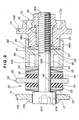
- a conical spring washer 52, a metal washer 53, and a rubber ring disc 54 are disposed between the double tube head 44 of the lock lever 40 and the sector member 33 of the throttle lever 30 in the order named when viewed from the double tube head 44.
- a rubber ring disc 54, a metal washer 53 and a conical spring washer 52 are disposed between the sector member 33 of the throttle lever 30 and the base 14a of the head member 14 in the order named when viewed from the sector member 33.
- the conical spring washers 53 form a resilient means of the throttle lever holding mechanism 50 which is disposed behind the second cam 47 (FIG.
- the rubber ring discs 54 form a friction member of the throttle lever holding mechanism 50 which is disposed between the throttle lever 30 and the lock lever 40 and is adapted to be forced against the throttle lever 30 when coaction between the first and second cams 23, 47 causes the lock lever 40 to be displaced toward the throttle lever 30 against the resiliency of the resilient mens (conical spring washers) 52.
- numeral 60 denotes a fine adjustment lever 60 attached by a screw 66 to the support lug 35 of the throttle lever 30 for achieving fine adjustment of the throttle position.
- the headed support shaft 61 has a long shank 61b extending through the conical spring washer 52, metal washer 53, rubber ring disc 54, arcuate guide hole 34 of the sector section 33, rubber ring disc 54, metal washer 53, conical spring washer 52, metal washer 53, double tube head 44 of the lock lever 40 and through-hole 23a of the cylindrical cam 23.
- a nut 62 is threaded with an externally threaded fore end portion 61c (FIG. 8) of the shank 61b of the support shaft 61, as shown in FIGS. 6-8.
- reference numeral 67 denotes a return spring acting between the throttle lever 30 and the head portion 12 to urge the throttle lever 30 toward an original unlock position.
- a tension coil spring 68 has one end connected to the hook-shaped spring retainer 43 of the lock lever 40 and the other end connected by a screw 69 to the spring retaining lug 19 on the head member 13. The spring 68 urges the lock lever 40 in an original stand-by position in which the lever portion 41 is forced against the lower oblique flat surfaces of the sleeves 17, 18, as shown in FIG. 5.
- the cylindrical first cam 23 formed integrally with the inner surface of the base 13a of the head member 13 is a fixed cam
- the second cam 47 formed at the bottom of the cylindrical extension 46a of the double tube head 44 of the lock lever 40 is a movable cam.
- the cam surface 24 formed on an end face of the cylindrical first cam 23 has an annular shape.
- the cam surface 24 has alternate ridges 24b and grooves 24a arranged in the circumferential direction of the cylindrical first cam 23.
- the grooves 24a and ridges 24b extend radially across the thickness of the cylindrical first cam 23.
- the ridges 24b each have opposite sidewalls or flanks 24c and 24e and a top 24d.
- the top 24d is flat and extends perpendicularly to an axis of the cylindrical first cam 23.
- One flank 24c which faces in the counterclockwise direction shown in FIG. 4, is beveled or sloped.
- the other flank 24e which faces toward the clockwise direction shown in FIG.
- locking direction is perpendicular to the flat top 24d and is parallel to the axis of the cylindrical first cam 23.
- the clockwise direction is the same as the direction of pivotal movement of the lock lever 40 toward a locking position. This direction is hereinafter referred to as "locking direction”.
- the cylindrical extension 46a of the double tube head 44 has an inside diameter determined to achieve a slid-fit connection between the double tube head 44 and the cylindrical first cam 23. This means that an inner peripheral surface 46b (FIG. 8) of the cylindrical extension 46a is in slide contact with an outer peripheral surface 23b of the cylindrical first cam 23.
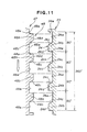
- the cam surface 48 of the movable second cam 47 which is formed on the annular end wall 44a at the bottom of the cylindrical bore 46a, has the same cam profile as the cam surface 24 of the first cam 23. More specifically, as shown in FIG. 11, the cam surface 48 has alternate ridges 48b and grooves 48a arranged in the circumferential direction of the annular end wall 44a, so that the ridges 48b of the second cam 47 can interdigitate with the ridges 24b of the first cam 23. Beveled or sloped flanks 48c of the ridges 48b face toward the locking direction (indicated by the profiled arrow in FIG. 11) which is opposite to the direction of facing of the sloped flanks 24c of the first cam 23.
- the grip portion 11 has an elongated recess 11a formed in a rear surface of the grip portion 11 along an upper member of the grip portion 11.
- the recess 11a accommodates within it the lever portion 41 of the lock lever 40 when the lock lever 40 is fully depressed, as shown in FIG. 9.
- the control cable 37 includes a control wire 37a connected at one end to the anchor pin 38 and, at the other end, to the control shaft of the throttle valve (not shown) of the engine 3 (FIG. 1).
- the control cable 37 further has an upper sheath or jacket 37b covering an upper portion of the control wire 37a, and a lower sheath or jacket 37c connected to a lower end of the upper jacket 37b and covering the remainder of the control wire 37a.
- the lower jacket 37c has a larger diameter than the upper jacket 37b.
- the upper jacket 37b has at its upper end a guide sleeve 37d of metal. The metal guide sleeve 37d is held within a retainer pocket 13h formed integrally with the base 13a of the head member 13 at a portion above the cutout portion 13f.
- the pipe 20 has a radial hole or opening 20a located near a lower opening 11b of the grip portion 11, so that the control cable 37 can be drawn out from the operation-control lever 10 through the radial opening 20a of the pipe 20 and the lower opening 11b of the grip portion 11.
- a lower end portion of the pipe 20 is drawn out from the lower opening 11b of the grip portion 11 and is connected to the support rod 5.
- the cylindrical head 32 of the throttle lever 30 is slidably fitted around the sleeves 15, 16 for pivotal movement about a common axis of the sleeves 15, 16.
- the return spring 67 is a torsion coil spring having a coiled portion 67a wound around the cylindrical head 32.
- One end 67b of the spring 67 is urged against an upper part of the peripheral wall 13b of the head member 13.
- the other end 67c of the spring 67 is anchored to a base portion of the throttle lever 31.
- the throttle lever 30 is urged to turn clockwise in FIG. 5 about the axis of the sleeves 15,16 by the resiliency of the torsion coil spring 67, so that the throttle lever 30 is normally held in the stand-by position shown in FIG. 5.
- the inner tube 45 (FIG. 6) of the double tube head 44 of the lock lever 40 is slidably fitted around the shank 61b of the support shaft 61 so that the lock lever 40 is pivotally movable about an axis of the support shaft 61.
- the lever portion 41 of the lock lever 40 project obliquely and downwardly from the elongated opening 12c of the head portion 12.
- the tension coil spring 68 acting between the hook-shaped spring retainer 43 of the lock lever 40 and the spring retaining lug 19 on the head member 13 urges the lock lever 40 to turn counterclockwise in FIG. 5 about the axis of the support shaft 61.
- the lock lever 40 is normally held in the stand-by position of FIG. 5 in which the lever portion 41 is forced against the lower oblique flat surfaces of the sleeves 17, 18.
- the support lug 35 on the sector member 33 of the throttle lever 30 is loosely received in the oblong hole 22 in the base 14a of the head member 14 with its cross-sectionally non-circular portion (including the flat surfaces 35a, 35a) projecting from an outside surface of the base 14a of the head member 14.
- the cross-sectionally non-circular portion including the flat surfaces 35 is received in a recess 60a of the fine adjustment lever 60 which is attached by the screw 66 to the support lug 35. Since the recess 60a has a non-circular cross section complementary in shape to the non-circular cross section of the support lug 35, the fine adjustment lever 60 is non-rotatable relative to the support lug 35.
- the fine adjustment lever 60 is located on the left side of the head portion 12, as shown in FIGS. 2 and 9.
- the support shaft 61 comprises a hexagon socket head cap screw having an enlarged cylindrical socket head 61a, a long shank 61b and a male screw 61c externally threaded on a fore end portion of the shank 61b.
- the socket head 61a is slidably received in the through-hole 21 of the base 14a of the head member 14 and has a hexagonal hole 61d for receiving therein the tip of a tool, such as a hexagonal bar wrench.
- a tool such as a hexagonal bar wrench
- the shank 61b of the support shaft 61 extends through the arcuate guide hole 34 of the sector member 33 of the throttle lever 30, and an axial through-hole 45a of the double tube head 45 of the lock lever 40.
- the male screw 61c of the support shaft 61 is threaded through an insert nut 70 press-fitted in the axial central hole 23a of the fixed first cam 23.
- a fore end portion of the male screw 61c projects from the insert nut 70, and the nut 62 is threaded with the projecting fore end portion of the male screw 61c to lock the support shaft 61 in position against movement relative to the head portion 12.
- the nut 62 serves as a lock nut.
- the lock nut 62 is partly received in an annular recess 13i formed in the outside surface of the base 13a of the head member 13.
- the insert nut 70 may be replaced by a sleeve (not shown).
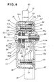
- the cam surface 24 of the fixed cylindrical first cam 23 and the cam surface 48 of the movable second cam 47 are held in pressure contact with each other with the outer peripheral surface 23 of the fixed cylindrical first cam 23 being in sliding contact with the inner peripheral surface 46b of the cylindrical extension 46a of the double tube head 44 of the lock lever 40. Since the cylindrical first cam 23 is slidably received in the cylindrical extension 46a, any foreign matter including dirt and dust is no longer possible to get into the cylindrical extension 46a. Thus, the cam surfaces 24, 48 of the first and second cams 23, 47 are completely free from contamination with dirt and dust and can operate stably and reliably over a long period of use.
- the conical spring washer 52, the washer 53 and the rubber ring disk 54 are disposed between the enlarged cylindrical head 61a of the support shaft 61 and one side surface of the sector member 33 of the throttle lever 30 in the order named when viewed from the head 61a toward the sector member 33.
- the rubber ring disk 54, the washer 53 and the conical spring washer 52 are disposed between the other side surface of the sector member 33 and one end face of the double tube head 44 of the lock lever 40 in the order named when viewed from the sector member 33 toward the double tube head 44.
- the conical spring washers 52 are disposed behind the movable second cam 47 when viewed from the fixed first cam 23 and form a resilient means for resiliently urging the cam surface 48 of the second cam 47 into pressure contact with the cam surface 24 of the first cam 23.
- the conical spring washers 52 also serve as a bias means for resiliently urging the rubber ring disks 54 against the opposite side surfaces of the sector member 33 of the throttle lever 30 when the lock lever 40 is displaced along the axis of the support shaft 61 toward the throttle lever 30 by coaction of the first and second cams 23, 47.
- the rubber ring disks 54 form a friction means adapted to be forced by the biasing means 52 against the sector member 33 of the throttle lever 30 to frictionally hold the throttle lever 30 in a desired operating position.
- the first and second cams 23, 47, the resilient means 52 and the friction member 54 jointly form the afore-mentioned throttle-lever holding mechanism 50.
- the resilient force exerted from the throttle-lever holding mechanism 50 onto the throttle lever 30 can be adjusted by turning the hexagonal socket head 61a of the support shaft 61 by use of a hexagonal bar wrench (not shown) while the lock nut 62 is kept loosened so that the support shaft 61 is displaced relative to the head member 13 in the axial direction of the support shaft 61.
- the resilient force is adjusted such that the rubber ring disks 54 are in light pressure contact with the opposite side surfaces of the sector member 33 of the throttle lever 30.
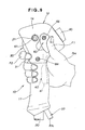
- the operation control lever unit 10 is gripped for manipulation by one hand (right hand RH, for example) of the operator M (FIG. 1).
- one hand right hand RH, for example
- an upper part of the grip portion 11 and a lower part of the head portion 12 are held in a palm of the right hand RH.
- the index finger R2 of the right hand RH is placed on the lever portion 31 of the throttle lever 30, the thumb F1 is placed on the back of the fine adjustment lever 60, and the remaining fingers are used to grasp the upper part of the grip portion 11.
- the index finger F2 is pulled to depress the throttle lever portion 31 until it reaches a desired position.
- the lever portion 41 of the lock lever 40 is depressed into the recessed portion 11a (FIG.
- the lock lever 40 turns clockwise in FIG. 10 about the support shaft 61 against the force of the return spring 68.
- the movable second cam 47 on the double tube head 44 turns about the support shaft 61 in the same direction as the lock lever 40. Accordingly, by a camming action between the respective cam surfaces 24, 48 of the first and second cams 23, 47, the rotary motion of the lock lever 40 is translated into a linear motion of the lock lever along the axis of the support shaft 61 in a direction toward the throttle lever 30.
- the lateral movement of the double tube head 44 causes the conical spring washers 52, 53 (FIG. 8) to be compressed into a substantially fully distorted flattened position between the hexagonal socket head 21a of the support shaft 61 and the washer 52.
- the conical spring washers 52, 53 With this distortion of the conical spring washers 52, 53, the rubber ring plates 54, 54 are strongly forced against the opposite surfaces of the sector member 33 of the throttler lever 30, so that the throttle lever 30 is held in a desired position against pivotal movement.
- One example of such desired position is the full-throttle position shown in FIG. 10.
- the oblong guide hole 34 of the throttle lever 30 extends arcuately about the axis of the sleeves 15, 16, the throttle lever 30 can smoothly turn about the axis of the sleeves 15, 16 while the sector member 33 is guided by sliding engagement between the guide hole 34 and the shank 61 of the support shaft 61.
- the fine adjustment lever 60 is firmly secured by the screw 66 to the distal end of the support lug 35 projecting from the sector member 33 of the throttle lever 30 through the oblong guide hole 22 to the outside of the head portion 12 of the operation-control lever unit 10.
- a ball of the thumb F1 is placed on the back of the fine adjustment lever 60, as shown in FIG. 9, then forced forwardly by the thumb F1 while a certain pressure is continuously applied from the index finger F2 to the lever portion 31 of the throttle lever 30.
- the forced forward movement of the fine adjustment lever 60 cause the throttle lever 30 to turn clockwise in FIG. 10 about the axis of the sleeves 15, 16 against a frictional force acting between the opposite surfaces of the sector member 33 and the spring biased rubber ring plates 54, 54 (FIG. 8) of the throttle-lever holding mechanism 50.
- the support lug 35 on the sector member 33 is guided by and along the arcuate oblong hole 22 formed in the base 14a (FIG. 7) of the head member 14.
- the sector member 33 slips on two opposed surfaces of the ruber ring plates 54, 54.
- the fine adjustment lever 60 is forced by the thumb F1 in the forward direction to cause the throttle lever 30 to separate from the full-throttle position of FIG. 10 and returns toward its original idling position of FIG. 5.
- the throttle valve incorporated in the carburetor of the engine 3 is operated in a direction to lower the engine speed (corresponding to power of the engine 3).
- the lock lever 40 is continuously held in its fully depressed locking position shown in FIG. 10. 10.
- the fine adjustment lever 60 is displaced in the forward direction of the head portion 12 by forcing or pushing it with the thumb F1.
- the thumb F1 when used to push the fine adjustment lever 60 can produce a greater power than when used to pull the same lever 60.
- manipulation of the fine adjustment lever 60 using the thumb F1 can be achieved with utmost ease and high reliability even though the throttle-lever holding mechanism 50 continuously operates to frictionally hold the throttle lever 30 in position against pivotal movement while the lock lever 40 is in its fully depressed position.
- the cam mechanism which forms an essential part of the throttle-lever holding mechanism 50 (FIG. 8).
- the cam mechanism is formed by the stationary cam 23 and the movable cam 47. These cams 23, 47 have respective cam surfaces 24, 48 engaged with each other.
- the cam surface 24 of the stationary cam 23 have four grooves 24a and four ridges 24b provided alternately at equal angular intervals of 90 degrees.
- the ridges 24b have the same height.
- the top surfaces 24b of the ridges 24b and the bottom surfaces of the grooves 24a are flat, parallel with each other, and perpendicular to the axis of the annular stationary cam 23.
- the flat top surfaces 24d have a predetermined width (corresponding to an extent in the circumferential direction of the cam surface 28).
- One sidewall or flank 24c of each ridge 24b is sloped, and the other flank 24e is perpendicular to the top surface 24d and the bottom surface of the groove 24a.
- the ridges 24b have a maximum width (including the width of the associated sloped flanks 24c) which is smaller than the width of the grooves 24a.
- the cam surface 48 of the movable cam 47 have four grooves 48a and four ridges 48b provided alternately at equal angular intervals of 90 degrees.
- the ridges 48b have the same height.
- the top surfaces 48b of the ridges 48b and the bottom surfaces of the grooves 48a are flat, parallel with each other, and perpendicular to the axis of the annular movable cam 47.
- the flat top surfaces 48d have substantially the same width as the flat top surfaces 24d of the ridges 24b.
- One sidewall or flank 48c of each ridge 48b is sloped, and the other flank 48e is perpendicular to the top surface 48d and the bottom surface of the groove 48a.
- a maximum width of the ridges 8b (including the width of the associated sloped flanks 48c) is substantially the same as that of the ridges 24b and is smaller than the width of the grooves 48a.
- the sloped flanks 48c of the cam surface 48 and the sloped flanks 24c of the cam surface 24 face in opposite directions so that they are slidably engaged with each other when the movable cam 24 is turned, relative to the stationary cam 23, in a direction indicated by the profiled arrow shown in FIG. 11.
- the ridges 48b of the cam surface 48 are in mesh with the ridges 24b of the cam surface 24.
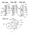
- FIG. 13 shows in comparative purposes a cam mechanism composed of two circular disc cams 123 and 147 each having on its one end face a cm surface 124, 148 including four ridges 124b, 148b formed contiguously in the circumferential direction.
- the ridges 124b, 148b have a triangular cross section and are separated by perpendicular walls 124a, 148a.
- the disc cam 123 is regarded as a stationary cam corresponding to the cam 23 (FIG. 3) formed integrally with the head member 13
- the disc cam 147 is regarded as a movable cam corresponding to the cam 48 (FIG. 3) integral with the lock lever 40.
- the cam mechanism shown in FIG. 13 operates as follows.
- the tip-to-tip engagement between the ridges 124b, 148b of the cams 123, 147 is unstable, ans so when the force exerted on the lock lever 40 changes due to a change in working condition, a change in working posture, vibrations of the engine, or external shock forces, the movable cam 148 tends to turn in the opposite direction under the bias of the conical spring washers 52, causing the ridges 148b to slide down along the ridges 124b of the stationary cam 123, as shown in FIG. 12C.
- One of the cams 23, 47 may have ridges of a triangular cross-section similar to those 124b, 148b of the cams 123, 147.
- the number of the ridges 24b, 48b should by no means be limited to four in the illustrated embodiment and may be two, three, five or more ridges may be employed.
- the stationary cam 23 formed integrally with the head member 13 of the operation-control handle 10 may be replaced with a separate cam 23 firmly secured to the head member 13.
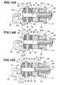
- FIGS. 15A-15C illustrate the manner in which a frictional force acting between the rubber ring discs 54 of the throttle-lever holding mechanism 50 and the sector member 55 of the throttle lever 30 is adjusted.
- the throttle-lever holding mechanism 50 In the initial condition (corresponding to the position shown in FIG. 8), the throttle-lever holding mechanism 50 is in the position (neutral position) shown in FIG. 15A.
- the support shaft 61 is rotated by the bar wrench 90 in the clockwise direction indicated by the solid-lined arrow shown in FIG. 15A.
- the support shaft 61 moves rightwards relative to the insert nut 70 and the head member 13 against the forces of the conical spring washers 52, 52, as indicated by the solid-lined arrow shown in FIG. 15B.
- the conical spring washers 52 are deflected in a somewhat flattened position and has a height B.
- the foregoing friction increasing adjustment is particularly useful when the coefficient of friction of the rubber ring discs 50 becomes small due to aging or deterioration by time. Additionally, the friction can be adjusted only by turning the support shaft 61 to move the same in an axial direction without exerting any adverse effect on another mechanism.
- the support shaft 61 When the friction between the sector member 33 and the rubber ring discs 54 is to be decreased, the support shaft 61 is rotated by the bar wrench 90 in the counterclockwise direction indicated by the broken-lined arrow shown in FIG. 15A. By virtue of threading engagement between the screw portion 61c and the insert nut 70, the support shaft 61 moves leftwards relative to the insert nut 70 and the head member 13 under the forces of the conical spring washers 52, 52, as indicated by the broken-lined arrow shown in FIG. 15C. When the support shaft 61 is displaced leftward by a distance Y from the neutral position of FIG. 15A, the conical spring washers 52 are allowed to axially expand and has a height C.
- the foregoing friction decreasing adjustment is particularly useful when the initially set friction is too large for the operator to manipulate the throttle lever 30.
- the friction increasing adjustment mentioned previously the friction decreasing operation can be achieved by merely turning the support shaft 61 and does not exert any influence on the operation of another mechanism.
- the lock nut 62 is threaded over the screw portion 61c of the support shaft 61 to lock the support shaft 61 at the desired position relative to the head portion 12 of the operation-control handle 10.
- this friction adjustment it is possible to grip the sector member 33 between the rubber ring discs 52, 52 to frictionally hold the throttle lever 30 in a desired position.
- a force required to turn the lock lever 40 to activate the throttle-lever holding mechanism 50 can be adjusted at a desired value.
- the friction on the throttle lever 40 can be easily adjusted by displacing the support shaft 61 in the axial direction by turning the support shaft 61 in such a manner that the adjusted friction is suited for the operator.
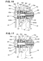
- FIG. 16 shows a modified form of the throttle-lever holding mechanism 50 according to the present invention, the modified mechanism 150 being in the state corresponding to the standby position of the lock lever 40.
- these parts which are identical to those in the embodiment shown in FIG. 8 are designated by the same reference characters, and further description thereof can, therefore, be omitted.
- the modified throttle-lever holding mechanism 150 includes a stationary cam 23 formed integrally with the head member 13, and a movable cam 47 provided at the bottom of a first axial recess 144a formed in one end face of a cylindrical head 144 of the lock lever 40.
- the axial recess 144a is slidably fitted over a peripheral surface of the stationary cam 23 which is cylindrical in shape.
- the cylindrical head 144 further has a second axial recess 144b formed in the opposite end face of the cylindrical head 144.
- a conical spring washer 152 fitted around the shank 61b of a support shaft 61 is received in the second axial recess 144b and fixed in position by a stop ring 171 attached to the support shaft 61 such that the conical spring washer 152 preloaded between the cylindrical head 144 and the stop ring 171.
- the conical spring washer 152 urges the cylindrical head 144 rightwards to keep the movable cam 48 in engagement with the stationary cam 23.
- the throttle-lever holding mechanism 150 further includes two rubber ring discs (friction members) 154, 154 fitted around the shank 61b of the support shaft 61 and disposed on opposite sides of the sector member 33 of the throttle lever 30, and two metal washers 153, 153 fitted around the shank 61b and each disposed on the outer side of one of the rubber ring discs 152, 152.
- One of the metal washers 153 is disposed between the head 61a of the support shaft 61 and one of the rubber ring discs 152, and the other metal washer 153 is disposed between the other rubber ring disc 152 and the cylindrical head 144 of the lock lever 40.
- the cylindrical head 144 further has a central annular third recess 144c facing the peripheral surface of the shank 61b.
- the annular recess 172 is filled with an oil-impregnated sponge rubber or O-ring 172.
- the metal washer 153 disposed between the sector member 33 and the cylindrical head 144 is separated by a space from the cylindrical head 144.
- the force of the conical spring washer 152 does not act on the sector member 33 of the throttle lever 30.
- the throttle lever 30 is held in the standby position of FIG. 5 by the force the return spring 67.
- the rubber ring discs 154 disposed on opposite sides of the sector member 33 is axially compressed between an under surface 61e of the head 61a of the support shaft 61 and the cylindrical head 144 of the lock lever 40.
- the sector member 33 is firmly gripped between the rubber ring discs 154, 154 with the result that the throttle lever 30 is locked in position against pivotal movement.
- the throttle lever 30 can be manipulated with a lesser force or pressure than the throttle lever operationally connected with the throttle-lever holding mechanism 50 of the first embodiment.
- the required manipulating force is at least greater than a combined force of the force of return spring 67 and the biasing force applied to the control cable 37.
- the conical spring washers 52, 152 of the throttle-lever holding mechanisms 50, 150 may be replaced with compression coil springs having a small axial length.
- the operation-control lever unit is used in the carrying bush cutter.
- the operation-control lever unit according to the present invention may be employed in other engine-powered working machines, such as shown in FIGS. 18-21.
- FIG. 18 shows a chainsaw 201 driven by an engine 203.
- the engine-driven chainsaw 201 has a grip handle 210 projecting laterally from a body 203a of the chainsaw 201, and an operation handle 210 projecting forwardly and upwardly from the engine 203.
- the grip handle 207 is gripped by a left hand LH of the operator M, and the operation handle 210 is gripped by a right hand RH of the operator M.
- the operation handle 210 is equipped with the operation-control lever unit of the present invention described above for controlling rotational speed of the engine 203.
- the chainsaw 201 has a cutting blade 206 with teeth on an endless chain projecting forwardly from the body 203a for trimming trees.
- FIG. 19 shows a chemical sprayer 301 driven by an engine 303 carried on the back of the operator M via a frame 302.
- the frame 302 also carries thereon a chemical tank 390 disposed below the engine 303.
- the chemical tank 390 has a built-in pump driven by the engine 303.
- the chemical sprayer 301 has a spray nozzle 306 attached to the top of a rigid pipe 305, and a flexible hose 304 connecting the rear end of the pipe 305 and the chemical tank 390.
- An operation handle 307 is provided on the rear end of the pipe 305 and is gripped by a right hand of the operator M.
- the operation handle 307 is equipped with the operation-control lever unit of the present invention described above.
- the pump driven by the engine 303 forces a chemical fluid to be drawn from the tank 390 and sprayed out from the spray nozzle 306 onto trees and plants.
- FIG. 20 shows a blower 401 driven by an engine 403 carried on the back of the operator M via a frame 402.
- the engine-driven blower 401 includes a blower pipe 405 having a nozzle 405a at a front end thereof, a flexible hose 404 interconnecting a rear end of the pipe 405 and a compressor 490 driven by the engine 403.
- An operation handle 410 is provided on a rear end portion of the pipe 405 and gripped by a right hand RH of the operator M.
- the operation handle 410 is equipped with the operation-control lever unit of the present invention. Pressurized air supplied from the engine-driven compressor 490 is forced out from the nozzle 405a to collect dust, leaves, trash on the roads.
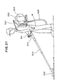
- FIG. 21 shows a vacuum dust collector 501 driven by an engine 503 carried on the back of the operator M via a frame 502.
- the vacuum dust collector 501 includes a vacuum generator 590 driven by the engine 503, a rigid pipe 505 connected to the vacuum generator 590 via a flexible hose 504, and a vacuum attachment 506 attached to a front end of the pipe 505 for collecting, by suction, dust, leaves and trash on the roads.
- An operation handle 510 is provided on a rear end portion of the pipe 505 and gripped by a right hand RH of the operator M.
- the operation handle 510 is equipped with the operation-control lever unit of the invention described above.
- An operation-control lever unit for regulating engine power of an engine-powered working machine to control operation of a working tool includes a throttle-lever holding mechanism (50) operative in response to pivotal movement of a lock lever (40) in a locking direction to frictionally hold the throttle lever (30) at a desired position.
- the throttle-lever holding mechanism (50) includes a stationary cam (23) on the head portion (12), a movable cam on the lock lever (40) and cooperating with the stationary cam (23) to displace the lock lever (40) along a support shaft (61) in a direction away from the stationary cam (23), and a resilient member (52) disposed behind the movable cam (47) and resiliently urging the movable cam (47) toward the stationary cam (23).
Description
- The present invention relates to an operation-control lever unit for regulating power of an engine of an engine-powered working machine to control operation of a working tool of the engine-powered working machine. The engine-powered working machine may include a carrying bush cutter, a chemical sprayer, a vacuum dust collector and so on.
- A carrying bush cutter having a circular cutter driven for rotation by an engine carried on the back of an operator is known from Japanese Utility Model Publication No. (SHO) 63-14035. The circular cutter is attached to one end of a hand-operating rod. The rod is provided with an operation handle near the other end thereof. In use of the known bush cutter, the operator swings the rod up and down and right and left while gripping the operation handle. With this swinging operation, bushes are cut or removed by the rotating circular cutter.
- In order to control the rotational speed of the cutter, output power of the engine is regulated by a throttle lever provided on a grip portion of the operation handle. However, because the operator is forced to continue gripping of the throttle lever and the operation handle throughout the bush-removing work, a heavy work load is put on the operator.
- According to somewhat successful prior improvements, a lock mechanism is associated with a throttle lever to temporarily lock the throttle lever in a desired position, so that the work load on the operator can be reduced. Typical examples of the prior improvements are disclosed in Japanese Utility Model Publication Nos. (SHO) 53-42661 and (SHO) 55-21536, Japanese Utility Model Laid-open Publication No. (SHO) 60-41539, and Japanese Patent Laid-open Publication No. (HEI) 8-303263.
- According to the disclosed operation lever units, the throttle lever is displaced to a predetermined operating position, then locked in this operating position by activating the lock mechanism. The lock mechanism is released at need.
- More specifically, the operation lever unit disclosed in Japanese Utility Model Publication Nos. (SHO) 55-21536 includes a throttle adjustment lever and a throttle release lever provided side by side on the operating handle. However, because these levers have different axes of pivotal movement, the operation lever unit is complicated in construction, requires an increased number of structural components, and is uneasy to manipulate. Additionally, due to wear and deformation occurring during a long period of use of the engine-powered working machine, a frictional force acting on the throttle lever to lock the same lever in position against pivotal movement tends to decrease and eventually allows the throttle lever to move from the locked position. The throttle lever may sometimes return to its original position when the operation lever unit is subjected to vibration. The operation lever unit has no means to adjust the frictional force acting on the throttle lever.
- In the operation lever unit shown in Japanese Utility Model Laid-open Publication No. (SHO) 60-41539, a throttle lever and a lock lever are mounted on the same pivot pin. However, due to a strong spring force acting directly on respective pivoted portions of the levers, a great muscular effort or force is required to turn each lever. Thus, the manipulability of the operating lever unit is relatively low. If the spring force is weakened, the lock lever will fail to lock the throttle lever at a desired position with sufficient reliability.
- The operation lever unit disclosed in Japanese Utility Model Publication No. (SHO) 53-42661 includes a locking pawl pivotally mounted between the pivot axis of a throttle lever and the pivot axis of a lock lever for operatively interlocking the two levers. Because of the presence of the locking pawl, the operating lever unit is complicated in construction and requires an increased number of structural components.
- In the operation lever unit shown in Japanese Patent Laid-open Publication No. (HEI) 8-303263, a throttle lever and a lock lever are pivotally mounted on the same pivot pin. However, because the lock lever is normally held stationary against pivotal movement using the force of a spring only, this operation lever unit has the same problem as the operation lever unit disclosed in Japanese Utility Model Laid-open Publication No. (SHO) 60-41539 previously described.
- The present invention is conceived to solve the foregoing problems associated with the prior art.
- A more specific object of the present invention is to provide a operation-control lever unit for an engine-powered working machine, which includes a throttle lever, a lock lever and a throttle-lever holding mechanism of simple construction having a relatively small number of components.
- Another object of the present invention is to provide an operation-control lever unit for an engine-powered working machine, which is simple in construction and is capable of reliably locking a throttle lever in a desired position to regulate output power of an engine of the engine-powered working machine while keeping good manipulability of a lock lever disposed close to the throttle lever.
- To achieve the foregoing objects, an operation-control lever unit of the present invention for regulating power of an engine of an engine-powered working machine to control operation of a working tool of the engine-powered working machine includes an operation-control handle having a grip portion and an enlarged head portion at an end of the grip portion, a throttle lever pivotably mounted to the head portion of the handle and pivotally movable about its pivot axis within a predetermined angular range, a lock lever pivotably mounted by a support shaft to the head portion and pivotally movable about an axis of the support shaft, the lock lever being slidably movable along the axis of the support shaft, and a throttle-lever holding mechanism operative in response to pivotal movement of the lock lever in a locking direction to frictionally hold the throttle lever at a desired position within the predetermined angular range. The throttle-lever holding mechanism includes a first cam coaxial with the support shaft and formed integrally with the head portion of the handle, a second cam coaxial with the support shaft and provided on the lock lever, the second cam being co-active with the first cam to displace the lock lever along the support shaft in a first direction away from the first cam, and a resilient means disposed behind the second cam when viewed from the first cam and resiliently urging the second cam toward the first cam.
- Because the first cam is integral with the head portion of handle, the throttle-lever holding mechanism is relatively simple in construction and has a small number of structural components.
- Preferably, one of the first and second cams has an integral tubular portion coaxial with the support shaft and projecting toward the other cam. The other cam has an outer peripheral surface slidably received in the tubular portion. With this arrangement, the cams are protected against contamination with dirt and dust and can smoothly operate in response to pivotal movement of lock lever.
- The first and second cams each have an annular cam surface having at least one radial ridge. At least one of the ridge of the first cam and the ridge of the second cam has a flat top surface. With this flat top surface, the throttle lever can be stably held in a locked position even when the lock lever is pivoted to some extent. The flat top surface is preferably perpendicular to the axis of the support shaft. The ridge may have a generally trapezoidal cross-sectional shape.
- Preferably, the throttle-lever holding mechanism further includes a friction member disposed between the throttle lever and the lock lever and forced against the throttle lever when coaction between the first and second cams displaces the lock lever in the first direction against the resiliency of the resilient means. The throttle-lever holding mechanism may also include a second friction member disposed opposite to the first-mentioned friction member with the throttle lever disposed therebetween. The first-mentioned friction member and the second friction member cooperate to grip the throttle lever therebetween when the lock lever is displaced in the first direction. The first-mentioned friction member and the second friction member are preferably rubber ring discs mounted on the support shaft.
- The resilient means is disposed between the lock lever and the friction member and urges the lock lever in a second direction to move the second cam toward the first cam and also urges the friction member into contact with the throttle lever. The resilient means is preferably a conical spring washer mounted on the support shaft.
- The resilient means may include a first resilient member disposed between the lock lever and the first-mentioned friction member, and a second resilient member disposed between the second friction member and a portion of the support shaft. The first resilient member urges the lock lever in a second direction to move the second cam toward the first cam and also urges the first-mentioned friction member into contact with the throttle lever. The second resilient member urges the second friction member into contact with the throttle lever.
- As an alternative, the resilient means may be disposed between the lock lever and the friction member urge the lock lever in a second direction to move the second cam toward the first cam. The resilient means is operatively separated from the friction member.
- In one preferred form of the invention, the resilient means is disposed between the lock lever and the friction member, and the throttle-lever holding mechanism further includes a friction adjustment device for varying a preloading on the resilient means to adjust a frictional force acting between the throttle lever and the friction member. The support shaft is a screw having a head slidably guided in a first portion of the head portion of the handle and a shank including a screw portion threaded with a second portion of the head portion. The resilient means, the friction member and the throttle lever are disposed between the head of the screw and the lock lever. The screw forms the friction adjustment device. By turning the screw, the screw moves in an axial direction. With this axial movement of the screw, the distance between the head of the screw and the lock lever varies with the result that a preloading on the resilient means is changed. Since the friction member is urged by the resilient means, the friction exerted from the friction member to the throttle lever can be adjusted by changing the proloading on the resilient means. The screw is preferably a hexagonal socket head cap screw. The friction adjustment device may further include a lock nut threaded with the screw portion of the screw to lock the screw in position against movement relative to the head portion.
- The above and other objects, features and advantages of the present invention will become manifest to those versed in the art upon making reference to the following description and accompanying sheets of drawings in which preferred structural embodiments incorporating the principle of the invention are shown by way of illustrative examples.
- FIG. 1 is a diagrammatical view of a carrying bush cutter as it is used in a bush-removing work as an engine-powered working machine in which an operation-control lever unit according to the present invention is incorporated;
- FIG. 2 is a perspective view of the operation-control lever unit including a grip handle;
- FIG. 3 is an exploded perspective view of a main portion of the operation-control lever unit;
- FIG. 4 is an enlarged view, with parts cutaway for clarity, showing a portion of FIG. 2 including a first cam and a second cam;
- FIG. 5 is a longitudinal cross-sectional view of the grip handle, showing the internal structure of the operation-control lever unit;
- FIG. 6 is a cross-sectional view taken along line VI-VI of FIG. 5;
- FIG. 7 is a cross-sectional view taken along line VII-VII of FIG. 5;
- FIG. 8 is an enlarged view of a part of FIG. 6, showing a throttle-lever holding mechanism of the operation-control lever unit;
- FIG. 9 is a side view of the grip handle showing a lock lever of the operation-control lever unit in its throttle-lock position;
- FIG. 10 is a longitudinal cross-sectional view of the grip handle showing the positional relationship between a throttle lever and the lock lever shown in FIG. 9;
- FIG. 11 is a developed view showing respective profiles of the first and second cams;
- FIGS. 12A, 12B and 12C are views similar to FIG. 12, but showing operation of the first and second cam which occurs in response to pivotal movement of the lock lever;
- FIG. 13 is a perspective view showing another cooperating pair of cams prepared for comparative purposes;
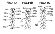
- FIGS. 14A, 14B and 14C are views corresponding to FIGS. 12A, 12B and 12C, respectively, but showing operation of the cams shown in FIG. 13;
- FIGS. 15A, 15B and 15C are cross-sectional views illustrative of the manner in which a frictional force acting between the throttle lever and a friction member of the throttle-holding mechanisms can be adjusted;
- FIG. 16 is a cross-sectional view showing a modified form of the throttle-lever holding mechanism as it is in a releasing position;
- FIG. 17 is a view similar to FIG. 16, but showing the throttle-lever holding mechanism in a locking position; and
- FIGS. 18 to 21 are diagrammatical views showing various modes of application of the engine-powered working machine in which the operating lever unit of the present invention can be used.
-
- Certain preferred embodiments of the present invention will be described below in greater detail with reference to the accompanying sheets of drawings wherein like or corresponding parts are designated by the same reference characters throughout several views.
- Referring now to FIG. 1, there is shown a carrying bush cutter 1 as it is used in a bush-removing work as an engine-powered working machine in which an operation-control lever unit according to the present invention is incorporated.
- The carrying bush cutter 1 includes a
frame 2, a power unit such as agasoline engine 3 mounted on theframe 2, aflexible tube 4 connected at one end to a power output portion of theengine 3, an elongated rigidhollow support rod 5 having one end (proximal end) connected to the other end of theflexible tube 4, and a circular cutter (working tool) 6 rotatably attached to the other end (distal end) of thesupport rod 5. The circular cuter 6 is connected in driven relation to theengine 3 via a flexible power transmission shaft (not shown) extending through thesupport rod 6 and theflexible tube 4. Thus, thecircular cutter 6 is driven in rotation by output power of theengine 3. - A
grip handle 7 and an operation-control handle 10 are provided on a proximal end portion of thesupport rod 7. The operation-control handle 10 is disposed behind the grip handle 7 when viewed from the distal end of thesupport rod 5. The grip handle 7 and the operation-control handle 10 extend orthogonally from an upper surface of thesupport rod 3. - The
frame 2 has a pair of belts or straps (one being shown in FIG. 1) for enabling the operator M to carry theengine 3 on its back, with acushioning pad 9 disposed between the back of the operator M and theframe 2. In use of the carrying bush cutter 1, thesupport rod 5 is held on, for example, the right side of a body of the operator M, with thegrip handle 7 and the operation-control handle 10 being gripped by the left hand LH and the right hand RH of the operator M, respectively. Thesupport rod 5 is swung right and left and up and down about its proximal end so that bushes are cut or removed by the rotatingcircular cutter 6. - The left hand LH of the operator M is used essentially for gripping the
grip handle 7 and moving thesupport rod 5 right and left and up and down. The right hand RH is used for gripping the operation-control handle 10 and performing throttle adjustment to regulate output power of theengine 3. The operation-control handle 10 constitutes a main part of the operation-control lever unit of the present invention. - As shown in FIG. 2, the operation-
control handle 10 is in the form of the grip of a gun and includes atubular grip portion 11 secured at a lower end to thesupport rod 5 via a bracket (not shown), and anenlarged head portion 12 secured to an upper end of thegrip portion 11. - The
head portion 12 is a hollow member of split structure consisting of left and right head halves ormembers head portion 12. Thehead portion 12 has an elongate hole oropening 12a formed in a front wall thereof. Athrottle lever 30 and a lock lever 4C of the operation-control lever unit are pivotally mounted to thehead portion 12 within the pocket. Thethrottle lever 30 has a trigger-like lever portion 31 projecting forwardly and downwardly from theelongate opening 12a in the front wall of thehead portion 12. Similarly, thelock lever 40 has anactuating lever portion 41 projecting rearwardly and downwardly from an elongate hole oropening 12c (FIG. 5) formed in a rear wall of thehead portion 12. - An engine start
switch 80 for starting and stopping the engine 3 (FIG. 1) is provided on the rear wall of thehead portion 12 at a position above theopening 12c (FIG. 5). Additionally, a secondarythrottle adjustment lever 60 is provided on one side (left side in the illustrated embodiment) of thehead portion 12 for achieving fine adjustment of the position of thethrottle lever 30. - FIG. 3 shows in perspective the general arrangement of the operation-control lever unit of the present invention.
- As shown in FIG. 3, the
head members planar base peripheral wall base base peripheral wall 13b has fourcutout portions pentagonal head member 13. Similarly, theperipheral wall 14b has fourcutout portions cutout portions 13c, 13f being not shown) formed in consecutive four sides of thepentagonal head member 14. When the twohead members control head 12, the cutout portion 13c of theperipheral wall 13b and the corresponding unillustrated cutout portion of theperipheral wall 14b jointly form the above-mentionedelongate opening 12a (FIGS. 1 and 5). Similarly, thecutout portions opening 12b (FIG. 5) from which the engine start switch 60 projects outwardly. Thecutout portions elongated opening 12c (FIG. 5) which allows pivotal movement of thelock lever 40. - The
head member 13 has an integralcylindrical sleeve 15 projecting perpendicularly from an inside surface of theplanar base 13a. Thesleeve 15 is located near a front end of thehead portion 12. Thehead member 14 also has an integralcylindrical sleeve 16 projecting perpendicularly from an inside surface of theplanar base 14a. Thesleeve 16 is aligned with thesleeve 15. Thesleeve 15 of thehead member 13 has a through-hole, while thesleeve 16 of thehead member 14 has an internally threaded blind hole closed at one end by thebase 14a. Thehead members cylindrical sleeves planar bases head members sleeve 17 has a through-hole, while thesleeve 18 has an internally threaded blind hole closed by thebase 14a. Thesleeve 18 is longer than thesleeve 17. Respective outer peripheral surfaces of thesleeves head members sleeves base 13a are in abutment with thesleeves base 14a, respectively. - An internally threaded hollow cylindrical
spring retaining lug 19 projects perpendicularly from the inside surface of thebase 13a of thehead member 13. Thespring retaining lug 19 is located near an upper end of thehead member 13. Thecutout portions peripheral walls head portion 12 have a semicircular shape and jointly form a circular hole in which an upper end portion of ametal pipe 20 is fitted. Thepipe 20 is assembled with thehead members screw 64. The screw extends successively through ahole 14g in thehead member 14, a radial through-hole (not designated) in thepipe 20, and ahole 13g (FIG. 7) in thehead member 13 and is threaded into anut 65 so that thehead members pipe 20 are tightly fastened together. Thehandle portion 11 is fitted around thepipe 20. - The
head member 14 has a through-hole 21 formed in an intermediate portion of thebase 14a which is offset from the center of thebase 14a toward the front end of thebase 14a. The intermediate portion of thebase 14a has anannular flange 21a projecting from an outside surface of thebase 14a so that a longitudinal part of the through-hole 21 is defined by theannular flange 21a. The through-hole 21 is clearance-fit with anenlarged head 61a of asupport shaft 61. Thebase 14a further has an arcuateoblong hole 22 extending arcuately about a central axis of thesleeve 16. The arcuateoblong hole 22 is disposed rearwardly of the through-hole 21 when viewed from thesleeve 16. - The
head member 13 further has afirst cam 23 formed on the inside surface of thebase 13a in coaxial relation with the through-hole 21. Thefirst cam 23 is a cylindrical cam having an axial central through-hole 23a aligned with the through-hole 21 in thehead member 14. Thecylindrical cam 23 has an end face formed with a cam surface 24 (FIG. 4) facing thebase 14a of thehead member 14. Thecam surface 24 is profiled in a manner as described below with respect to FIG. 4. - The
throttle lever 30, thelock lever 40 and a throttle-lever holding mechanism 50 are disposed between thehead members second cams lever holding mechanism 50. - The
throttle lever 30 includes a hollowcylindrical head 32 formed integrally with an upper end of thelever portion 31, and asector member 35 projecting radially outwardly from thecylindrical head 32. Thesector member 31 has anarcuate guide grooves 34 extending arcuately about an axis of thecylindrical head 32. Thethrottle lever 30 further has asupport lug 35 projecting from an outer peripheral edge portion of one surface of thesector member 33 toward thehead member 14. Thesupport lug 35 is cutout or removed at diametrically opposite portions thereof so as to define a pair of diametrically oppositeflat surfaces 35a (FIG. 7) for a purpose described later. Thus, thesupport lug 35 has a non-circular cross section. - The
throttle lever 30 further includes atubular socket 36 projecting perpendicularly from the other surface of thesector member 33. Thesocket 36 rotatably receives therein ananchor pin 38 connected to one end of acontrol cable 37, as shown in FIG. 6. The other end of thecontrol cable 37 is connected to the control shaft of a throttle valve (not shown) of the engine 3 (FIG. 1). - The
lock lever 40 has a substantially rectangularflat base portion 42 integral with an upper end of thelever portion 41 and bent at right angles to thelever portion 41, and a hook-shapedspring retainer 43 provided at a lower end of thebase portion 42 adjacent thelever portion 41. - The
lock lever 40 further has acylindrical head 44 of double tube structure including a pair of concentric inner andouter tubes outer tube 46 has an integral hollowcylindrical extension 46a projecting from the joined end toward thebase 14a of thehead member 14. Thedouble tube head 44 is formed integrally with a distal end of thebase portion 42 at theextension 46a of theouter tube 46. The inner andouter tubes annular end wall 44a (FIG. 6) which forms the bottom of thecylindrical extension 46a. Thelock lever 40 has asecond cam 47 formed at the bottom of the cylindrical extension for coaction with thecam 23 formed on thehead member 13. Thecam 47 has acam surface 47 profiled in a manner described below with reference to FIG. 4. - In an assembled condition where the
throttle lever 30 and thelock lever 40 are pivotally mounted on thehead portion 12, aconical spring washer 52, ametal washer 53, and arubber ring disc 54 are disposed between thedouble tube head 44 of thelock lever 40 and thesector member 33 of thethrottle lever 30 in the order named when viewed from thedouble tube head 44. Similarly, arubber ring disc 54, ametal washer 53 and aconical spring washer 52 are disposed between thesector member 33 of thethrottle lever 30 and thebase 14a of thehead member 14 in the order named when viewed from thesector member 33. Theconical spring washers 53 form a resilient means of the throttlelever holding mechanism 50 which is disposed behind the second cam 47 (FIG. 4) when viewed from thefirst cam 23 and operates to urge thesecond cam 47 toward thefirst cam 23. Therubber ring discs 54 form a friction member of the throttlelever holding mechanism 50 which is disposed between thethrottle lever 30 and thelock lever 40 and is adapted to be forced against thethrottle lever 30 when coaction between the first andsecond cams lock lever 40 to be displaced toward thethrottle lever 30 against the resiliency of the resilient mens (conical spring washers) 52. - In FIG. 3, numeral 60 denotes a
fine adjustment lever 60 attached by ascrew 66 to thesupport lug 35 of thethrottle lever 30 for achieving fine adjustment of the throttle position. The headedsupport shaft 61 has along shank 61b extending through theconical spring washer 52,metal washer 53,rubber ring disc 54,arcuate guide hole 34 of thesector section 33,rubber ring disc 54,metal washer 53,conical spring washer 52,metal washer 53,double tube head 44 of thelock lever 40 and through-hole 23a of thecylindrical cam 23. Anut 62 is threaded with an externally threadedfore end portion 61c (FIG. 8) of theshank 61b of thesupport shaft 61, as shown in FIGS. 6-8. Twoscrews sleeves sleeves head members head portion 12. In an assembled condition, theperipheral walls head members - In FIG. 3,
reference numeral 67 denotes a return spring acting between thethrottle lever 30 and thehead portion 12 to urge thethrottle lever 30 toward an original unlock position. Atension coil spring 68 has one end connected to the hook-shapedspring retainer 43 of thelock lever 40 and the other end connected by ascrew 69 to thespring retaining lug 19 on thehead member 13. Thespring 68 urges thelock lever 40 in an original stand-by position in which thelever portion 41 is forced against the lower oblique flat surfaces of thesleeves - As shown in FIG. 4, the cylindrical
first cam 23 formed integrally with the inner surface of thebase 13a of thehead member 13 is a fixed cam, while thesecond cam 47 formed at the bottom of thecylindrical extension 46a of thedouble tube head 44 of thelock lever 40 is a movable cam. - Due to the axial central through-
hole 23a of the fixed cylindricalfirst cam 23, thecam surface 24 formed on an end face of the cylindricalfirst cam 23 has an annular shape. Thecam surface 24 hasalternate ridges 24b andgrooves 24a arranged in the circumferential direction of the cylindricalfirst cam 23. Thegrooves 24a andridges 24b extend radially across the thickness of the cylindricalfirst cam 23. Theridges 24b each have opposite sidewalls orflanks first cam 23. Oneflank 24c, which faces in the counterclockwise direction shown in FIG. 4, is beveled or sloped. Theother flank 24e, which faces toward the clockwise direction shown in FIG. 5, is perpendicular to the flat top 24d and is parallel to the axis of the cylindricalfirst cam 23. In FIG. 4, the clockwise direction is the same as the direction of pivotal movement of thelock lever 40 toward a locking position. This direction is hereinafter referred to as "locking direction". - The
cylindrical extension 46a of thedouble tube head 44 has an inside diameter determined to achieve a slid-fit connection between thedouble tube head 44 and the cylindricalfirst cam 23. This means that an innerperipheral surface 46b (FIG. 8) of thecylindrical extension 46a is in slide contact with an outerperipheral surface 23b of the cylindricalfirst cam 23. - The
cam surface 48 of the movablesecond cam 47, which is formed on theannular end wall 44a at the bottom of thecylindrical bore 46a, has the same cam profile as thecam surface 24 of thefirst cam 23. More specifically, as shown in FIG. 11, thecam surface 48 hasalternate ridges 48b andgrooves 48a arranged in the circumferential direction of theannular end wall 44a, so that theridges 48b of thesecond cam 47 can interdigitate with theridges 24b of thefirst cam 23. Beveled or slopedflanks 48c of theridges 48b face toward the locking direction (indicated by the profiled arrow in FIG. 11) which is opposite to the direction of facing of the slopedflanks 24c of thefirst cam 23. - When the
lock lever 30 is manually turned in the locking direction (clockwise direction in FIG. 5) about the axis of thedouble tube head 44, thecam surface 48 of thesecond cam 47 coacts with thecam surface 24 of thefirst cam 23 to displace thesecond cam 47 and thelock lever 30 along the support shaft 61 (FIG. 3) in a direction away from thehead member 13 against the resilient force of the conical spring washers 52 (FIG. 4). - As shown in FIG. 5, the
grip portion 11 has anelongated recess 11a formed in a rear surface of thegrip portion 11 along an upper member of thegrip portion 11. Therecess 11a accommodates within it thelever portion 41 of thelock lever 40 when thelock lever 40 is fully depressed, as shown in FIG. 9. - The
control cable 37 includes acontrol wire 37a connected at one end to theanchor pin 38 and, at the other end, to the control shaft of the throttle valve (not shown) of the engine 3 (FIG. 1). Thecontrol cable 37 further has an upper sheath orjacket 37b covering an upper portion of thecontrol wire 37a, and a lower sheath orjacket 37c connected to a lower end of theupper jacket 37b and covering the remainder of thecontrol wire 37a. Thelower jacket 37c has a larger diameter than theupper jacket 37b. Theupper jacket 37b has at its upper end aguide sleeve 37d of metal. Themetal guide sleeve 37d is held within aretainer pocket 13h formed integrally with thebase 13a of thehead member 13 at a portion above thecutout portion 13f. - The
pipe 20 has a radial hole oropening 20a located near alower opening 11b of thegrip portion 11, so that thecontrol cable 37 can be drawn out from the operation-control lever 10 through theradial opening 20a of thepipe 20 and thelower opening 11b of thegrip portion 11. A lower end portion of thepipe 20 is drawn out from thelower opening 11b of thegrip portion 11 and is connected to thesupport rod 5. - The
cylindrical head 32 of thethrottle lever 30 is slidably fitted around thesleeves sleeves return spring 67 is a torsion coil spring having a coiledportion 67a wound around thecylindrical head 32. By the resiliency of thetorsion coil spring 67, Oneend 67b of thespring 67 is urged against an upper part of theperipheral wall 13b of thehead member 13. Theother end 67c of thespring 67 is anchored to a base portion of thethrottle lever 31. Thus, thethrottle lever 30 is urged to turn clockwise in FIG. 5 about the axis of thesleeves torsion coil spring 67, so that thethrottle lever 30 is normally held in the stand-by position shown in FIG. 5. - The
support shaft 61 extending across the breath of thehead portion 12 penetrates thearcuate guide hole 34 in thesector member 33 of thethrottle lever 30. - The inner tube 45 (FIG. 6) of the
double tube head 44 of thelock lever 40 is slidably fitted around theshank 61b of thesupport shaft 61 so that thelock lever 40 is pivotally movable about an axis of thesupport shaft 61. Thelever portion 41 of thelock lever 40 project obliquely and downwardly from theelongated opening 12c of thehead portion 12. Thetension coil spring 68 acting between the hook-shapedspring retainer 43 of thelock lever 40 and thespring retaining lug 19 on thehead member 13 urges thelock lever 40 to turn counterclockwise in FIG. 5 about the axis of thesupport shaft 61. Thus, thelock lever 40 is normally held in the stand-by position of FIG. 5 in which thelever portion 41 is forced against the lower oblique flat surfaces of thesleeves - As shown in FIG. 7, the
support lug 35 on thesector member 33 of thethrottle lever 30 is loosely received in theoblong hole 22 in thebase 14a of thehead member 14 with its cross-sectionally non-circular portion (including theflat surfaces base 14a of thehead member 14. The cross-sectionally non-circular portion including theflat surfaces 35 is received in arecess 60a of thefine adjustment lever 60 which is attached by thescrew 66 to thesupport lug 35. Since therecess 60a has a non-circular cross section complementary in shape to the non-circular cross section of thesupport lug 35, thefine adjustment lever 60 is non-rotatable relative to thesupport lug 35. For the purpose of manipulation, thefine adjustment lever 60 is located on the left side of thehead portion 12, as shown in FIGS. 2 and 9. - As shown in FIG. 8, the
support shaft 61 comprises a hexagon socket head cap screw having an enlargedcylindrical socket head 61a, along shank 61b and amale screw 61c externally threaded on a fore end portion of theshank 61b. Thesocket head 61a is slidably received in the through-hole 21 of thebase 14a of thehead member 14 and has ahexagonal hole 61d for receiving therein the tip of a tool, such as a hexagonal bar wrench. When thesupport shaft 61 is to be rotated, the hexagonal bar having one end snugly received in thehexagonal hole 61d is turned. Thehead 61a may be shaped into a hexagonal form which is slidably receivable in the through-hole 21 and hence is rotatable relative to thehead portion 12. - As previously described, the
shank 61b of thesupport shaft 61 extends through thearcuate guide hole 34 of thesector member 33 of thethrottle lever 30, and an axial through-hole 45a of thedouble tube head 45 of thelock lever 40. Themale screw 61c of thesupport shaft 61 is threaded through aninsert nut 70 press-fitted in the axialcentral hole 23a of the fixedfirst cam 23. A fore end portion of themale screw 61c projects from theinsert nut 70, and thenut 62 is threaded with the projecting fore end portion of themale screw 61c to lock thesupport shaft 61 in position against movement relative to thehead portion 12. Thus, thenut 62 serves as a lock nut. Thelock nut 62 is partly received in anannular recess 13i formed in the outside surface of thebase 13a of thehead member 13. Theinsert nut 70 may be replaced by a sleeve (not shown). - The
cam surface 24 of the fixed cylindricalfirst cam 23 and thecam surface 48 of the movablesecond cam 47 are held in pressure contact with each other with the outerperipheral surface 23 of the fixed cylindricalfirst cam 23 being in sliding contact with the innerperipheral surface 46b of thecylindrical extension 46a of thedouble tube head 44 of thelock lever 40. Since the cylindricalfirst cam 23 is slidably received in thecylindrical extension 46a, any foreign matter including dirt and dust is no longer possible to get into thecylindrical extension 46a. Thus, the cam surfaces 24, 48 of the first andsecond cams - The
conical spring washer 52, thewasher 53 and therubber ring disk 54 are disposed between the enlargedcylindrical head 61a of thesupport shaft 61 and one side surface of thesector member 33 of thethrottle lever 30 in the order named when viewed from thehead 61a toward thesector member 33. - Similarly, the
rubber ring disk 54, thewasher 53 and theconical spring washer 52 are disposed between the other side surface of thesector member 33 and one end face of thedouble tube head 44 of thelock lever 40 in the order named when viewed from thesector member 33 toward thedouble tube head 44. - The
conical spring washers 52 are disposed behind the movablesecond cam 47 when viewed from the fixedfirst cam 23 and form a resilient means for resiliently urging thecam surface 48 of thesecond cam 47 into pressure contact with thecam surface 24 of thefirst cam 23. Theconical spring washers 52 also serve as a bias means for resiliently urging therubber ring disks 54 against the opposite side surfaces of thesector member 33 of thethrottle lever 30 when thelock lever 40 is displaced along the axis of thesupport shaft 61 toward thethrottle lever 30 by coaction of the first andsecond cams rubber ring disks 54 form a friction means adapted to be forced by the biasing means 52 against thesector member 33 of thethrottle lever 30 to frictionally hold thethrottle lever 30 in a desired operating position. The first andsecond cams friction member 54 jointly form the afore-mentioned throttle-lever holding mechanism 50. - The resilient force exerted from the throttle-
lever holding mechanism 50 onto thethrottle lever 30 can be adjusted by turning thehexagonal socket head 61a of thesupport shaft 61 by use of a hexagonal bar wrench (not shown) while thelock nut 62 is kept loosened so that thesupport shaft 61 is displaced relative to thehead member 13 in the axial direction of thesupport shaft 61. In the normal condition, the resilient force is adjusted such that therubber ring disks 54 are in light pressure contact with the opposite side surfaces of thesector member 33 of thethrottle lever 30. - Operation of the operation
control lever unit 10 will be described below with reference to FIG. 9. - In use of the carrying bush cutter 1 (FIG. 1), the operation
control lever unit 10 is gripped for manipulation by one hand (right hand RH, for example) of the operator M (FIG. 1). In this instance, an upper part of thegrip portion 11 and a lower part of thehead portion 12 are held in a palm of the right hand RH. The index finger R2 of the right hand RH is placed on thelever portion 31 of thethrottle lever 30, the thumb F1 is placed on the back of thefine adjustment lever 60, and the remaining fingers are used to grasp the upper part of thegrip portion 11. Then, the index finger F2 is pulled to depress thethrottle lever portion 31 until it reaches a desired position. Then thelever portion 41 of thelock lever 40 is depressed into the recessedportion 11a (FIG. 5) by a portion of the palm (a ball of the thumb, for example). As thelever portion 31 is depressed, thethrottle lever 30 turns counterclockwise in FIG. 9 about the axis of the screw 63 (FIG. 5). This achieves adjustment of the position of the throttle valve (not shown) to thereby regulate the engine speed. - Stated more specifically, as the
throttle lever 30 turns counterclockwise in FIG. 10 about thescrew 63 against the force of the return spring 67 (FIG. 5), thecontrol wire 37a of thecontrol cable 37 is pulled upwardly. With this upward movement of thecontrol cable 37, the throttle valve incorporated in the carburetor of the engine 3 (FIG.1) is turned in a direction to increase rotational speed of theengine 3. Thethrottle lever 30 shown in FIG. 10 is in the full-throttle position which defines an upper limits of an adjustable range of engine speed. - As the
lever portion 41 of thelock lever 40 is depressed by the palm part such as the ball of the thumb F1, thelock lever 40 turns clockwise in FIG. 10 about thesupport shaft 61 against the force of thereturn spring 68. In this instance, the movablesecond cam 47 on thedouble tube head 44 turns about thesupport shaft 61 in the same direction as thelock lever 40. Accordingly, by a camming action between the respective cam surfaces 24, 48 of the first andsecond cams lock lever 40 is translated into a linear motion of the lock lever along the axis of thesupport shaft 61 in a direction toward thethrottle lever 30. - The lateral movement of the
double tube head 44 causes theconical spring washers 52, 53 (FIG. 8) to be compressed into a substantially fully distorted flattened position between thehexagonal socket head 21a of thesupport shaft 61 and thewasher 52. With this distortion of theconical spring washers rubber ring plates sector member 33 of thethrottler lever 30, so that thethrottle lever 30 is held in a desired position against pivotal movement. One example of such desired position is the full-throttle position shown in FIG. 10. - The
oblong guide hole 34 of thethrottle lever 30 extends arcuately about the axis of thesleeves throttle lever 30 can smoothly turn about the axis of thesleeves sector member 33 is guided by sliding engagement between theguide hole 34 and theshank 61 of thesupport shaft 61. - As described above with reference to FIG. 7, the
fine adjustment lever 60 is firmly secured by thescrew 66 to the distal end of thesupport lug 35 projecting from thesector member 33 of thethrottle lever 30 through theoblong guide hole 22 to the outside of thehead portion 12 of the operation-control lever unit 10. - In operation, a ball of the thumb F1 is placed on the back of the
fine adjustment lever 60, as shown in FIG. 9, then forced forwardly by the thumb F1 while a certain pressure is continuously applied from the index finger F2 to thelever portion 31 of thethrottle lever 30. The forced forward movement of thefine adjustment lever 60 cause thethrottle lever 30 to turn clockwise in FIG. 10 about the axis of thesleeves sector member 33 and the spring biasedrubber ring plates 54, 54 (FIG. 8) of the throttle-lever holding mechanism 50. During pivotal movement of thethrottle lever 30, thesupport lug 35 on thesector member 33 is guided by and along the arcuateoblong hole 22 formed in thebase 14a (FIG. 7) of thehead member 14. Thesector member 33 slips on two opposed surfaces of theruber ring plates - Thus, when the engine 3 (FIG. 1) while running at a maximum speed is to be slowed down, the
fine adjustment lever 60 is forced by the thumb F1 in the forward direction to cause thethrottle lever 30 to separate from the full-throttle position of FIG. 10 and returns toward its original idling position of FIG. 5. With this pivotal movement of thethrottle lever 30, the throttle valve incorporated in the carburetor of theengine 3 is operated in a direction to lower the engine speed (corresponding to power of the engine 3). During that time, thelock lever 40 is continuously held in its fully depressed locking position shown in FIG. 10. 10. - The
fine adjustment lever 60 is displaced in the forward direction of thehead portion 12 by forcing or pushing it with the thumb F1. The thumb F1 when used to push thefine adjustment lever 60 can produce a greater power than when used to pull thesame lever 60. Thus, manipulation of thefine adjustment lever 60 using the thumb F1 can be achieved with utmost ease and high reliability even though the throttle-lever holding mechanism 50 continuously operates to frictionally hold thethrottle lever 30 in position against pivotal movement while thelock lever 40 is in its fully depressed position. - Then, explanation will be given of the cam mechanism which forms an essential part of the throttle-lever holding mechanism 50 (FIG. 8). As described above, the cam mechanism is formed by the
stationary cam 23 and themovable cam 47. Thesecams - As shown in FIG. 11, the
cam surface 24 of thestationary cam 23 have fourgrooves 24a and fourridges 24b provided alternately at equal angular intervals of 90 degrees. Theridges 24b have the same height. The top surfaces 24b of theridges 24b and the bottom surfaces of thegrooves 24a are flat, parallel with each other, and perpendicular to the axis of the annularstationary cam 23. The flattop surfaces 24d have a predetermined width (corresponding to an extent in the circumferential direction of the cam surface 28). One sidewall orflank 24c of eachridge 24b is sloped, and theother flank 24e is perpendicular to thetop surface 24d and the bottom surface of thegroove 24a. Theridges 24b have a maximum width (including the width of the associated slopedflanks 24c) which is smaller than the width of thegrooves 24a. - Similarly, the
cam surface 48 of themovable cam 47 have fourgrooves 48a and fourridges 48b provided alternately at equal angular intervals of 90 degrees. Theridges 48b have the same height. The top surfaces 48b of theridges 48b and the bottom surfaces of thegrooves 48a are flat, parallel with each other, and perpendicular to the axis of the annularmovable cam 47. The flattop surfaces 48d have substantially the same width as the flattop surfaces 24d of theridges 24b. One sidewall orflank 48c of eachridge 48b is sloped, and theother flank 48e is perpendicular to thetop surface 48d and the bottom surface of thegroove 48a. A maximum width of the ridges 8b (including the width of the associated slopedflanks 48c) is substantially the same as that of theridges 24b and is smaller than the width of thegrooves 48a. The slopedflanks 48c of thecam surface 48 and the slopedflanks 24c of thecam surface 24 face in opposite directions so that they are slidably engaged with each other when themovable cam 24 is turned, relative to thestationary cam 23, in a direction indicated by the profiled arrow shown in FIG. 11. In the normal condition where thelock lever 40 is in its standby position shown in FIG. 5, theridges 48b of thecam surface 48 are in mesh with theridges 24b of thecam surface 24. - A camming action of the cam mechanism which is induced by coaction between the
cam surface stationary cam 23 and thecam surface 48 of themovable cam 47 will be described with reference to FIGS. 12A to 12C. - In the normal condition in which the
lock lever 40 is in the standby position shown in FIG. 5, the cam surfaces 24, 48 are held in mutual interdigitating engagement under the bias of theconical spring washers ridges 24b (48b) of one cam surface 24 (48) being received in thegrooves 48a (24a) in the other cam surface 48 (24). - When the
lock lever 40 is turned clockwise in FIG. 5 so as to control pivotal movement of thethrottle lever 30, themovable cam 47 starts rotating in the direction of the arrow shown in FIG. 12A. Rotation of themovable cam 47 causes the slopedflanks 48c of thecam surface 48 of themovable cam 47 come into contact with the slopedflanks 24c of thecam surface 24 of thestationary cam 23, then slide up along the slopedflanks 24c. With this sliding movement of the slopedflanks 48c, themovable cam 47 is displaced in the left-hand direction in FIG. 12B against the forces of the conical spring washers 52 (FIG. 8). - As a consequence of the leftward movement of the
movable cam 47, the cylindrical double tube head 44 (FIG. 8) of thelock lever 40 slides along thesupport shaft 61 in the leftward direction in FIG. 8 with the result that therubber ring discs 54 are forced against the opposite surfaces of thesector member 33 of thethrottle lever 30 by the forces of theconical spring washers 52. Thus, a frictional force acting between theruber ring discs 54 and thesector member 33 increases. - Continued rotation of the
movable cam 48 causes the flat tops 48d of therespective ridges 48b of themovable cam 47 to come into sliding contact with the flat tops 24d of theridges 24b of thestationary cam 23, as shown in FIG. 12C. In this instance, themovable cam 47 is displaced leftwards from its original position by a distance corresponding to the height of theridges throttle lever 30 by the action of the throttle-lever holding mechanism 50 in response to pivotal movement of the lockinglever 40. In this locking position, theconical spring washers 52 are substantially fully deflected by the cylindricaldouble tube head 44 of thelock lever 40 so that therubber ring discs sector member 33 with maximum friction to thereby lock thethrottle lever 30 in position against pivotal movement. - Since the flat tops 24d, 48d of the
ridges cams throttle.lever 30 is be kept even when thelock lever 40 is further turned to some extent. - FIG. 13 shows in comparative purposes a cam mechanism composed of two
circular disc cams cm surface ridges ridges perpendicular walls 124a, 148a. Thedisc cam 123 is regarded as a stationary cam corresponding to the cam 23 (FIG. 3) formed integrally with thehead member 13, and thedisc cam 147 is regarded as a movable cam corresponding to the cam 48 (FIG. 3) integral with thelock lever 40. - The cam mechanism shown in FIG. 13 operates as follows.
- In the normal condition in which the
lock lever 40 is in the standby position shown in FIG. 5, theridges cams conical spring washers - When the
lock lever 40 is turned clockwise in FIG. 5, thecam 147 turned in the same direction, causing theridges 148b of themovable cam 147 slide up along theridges 124b of thestationary cam 123. When respective tip ends of theridges 148b arrive at the corresponding tip ends of theridges 124b, as shown in FIG. 14B, themovable cam 17 and thelock lever 40 are displaced leftwards to a maximum extent away from thestationary cam 123. In this condition, a throttle-holding mechanism including thecam mechanism sector member 33, thereby locking thethrottle lever 30 in position against pivotal movement. The tip-to-tip engagement between theridges cams lock lever 40 changes due to a change in working condition, a change in working posture, vibrations of the engine, or external shock forces, themovable cam 148 tends to turn in the opposite direction under the bias of theconical spring washers 52, causing theridges 148b to slide down along theridges 124b of thestationary cam 123, as shown in FIG. 12C. This means that the frictional force acting on thesector member 33 of thethrottle lever 30 under the forces of theconical spring washers 52 decreases, allowing thethrottle lever 30 to pivot in the direction to return to its original standby position. With this returning movement of thethrottle lever 30, engine speed is slowed down, making the operation of the circular cutter 6 (FIG. 1) unstable. Such unintentional slowing down of the engine speed does not occur in the device of the present invention because of the trapezoidal cross-sectional shape of theridges cams - One of the
cams cams ridges stationary cam 23 formed integrally with thehead member 13 of the operation-control handle 10 may be replaced with aseparate cam 23 firmly secured to thehead member 13. - FIGS. 15A-15C illustrate the manner in which a frictional force acting between the
rubber ring discs 54 of the throttle-lever holding mechanism 50 and the sector member 55 of thethrottle lever 30 is adjusted. In the initial condition (corresponding to the position shown in FIG. 8), the throttle-lever holding mechanism 50 is in the position (neutral position) shown in FIG. 15A. - When the frictional force is to be adjusted, the
lock nut 62 is loosened as shown in FIG. 15A. Thus, by turning ahexagonal bar wrench 90 in either direction of the arrow with its oneend 91 received in thehexagonal hole 61d in thehead 61a of thesupport shaft 61, thesupport shaft 61 is moved right or left relative to theinsert nut 70, thus enabling adjustment of the frictional force between thesector member 33 and therubber ring discs 54. In the neutral position, theconical spring washers 52 have a height A equal to the distance between theunder surface 61e of thehead 61a and themetal washer 53. - When the friction between the
sector member 33 and therubber ring discs 54 is to be increased, thesupport shaft 61 is rotated by thebar wrench 90 in the clockwise direction indicated by the solid-lined arrow shown in FIG. 15A. By virtue of threading engagement between thescrew portion 61c and theinsert nut 70, thesupport shaft 61 moves rightwards relative to theinsert nut 70 and thehead member 13 against the forces of theconical spring washers support shaft 61 is displaced rightward by a distance X from the neutral position of FIG. 15A, theconical spring washers 52 are deflected in a somewhat flattened position and has a height B. - With this rightward movement of the
support shaft 61, a preloading force exerted on theconical spring washers 52 is increased. Thus, therubber ring discs conical spring washers sector member 33 under a greater resilient force than that applied at the initial state. Consequently, the friction between thesector member 33 and therubber ring discs 52 increases, correspondingly. At the same time, the stationary andmovable cams - The foregoing friction increasing adjustment is particularly useful when the coefficient of friction of the
rubber ring discs 50 becomes small due to aging or deterioration by time. Additionally, the friction can be adjusted only by turning thesupport shaft 61 to move the same in an axial direction without exerting any adverse effect on another mechanism. - When the friction between the
sector member 33 and therubber ring discs 54 is to be decreased, thesupport shaft 61 is rotated by thebar wrench 90 in the counterclockwise direction indicated by the broken-lined arrow shown in FIG. 15A. By virtue of threading engagement between thescrew portion 61c and theinsert nut 70, thesupport shaft 61 moves leftwards relative to theinsert nut 70 and thehead member 13 under the forces of theconical spring washers support shaft 61 is displaced leftward by a distance Y from the neutral position of FIG. 15A, theconical spring washers 52 are allowed to axially expand and has a height C. - With this leftward movement of the
support shaft 61, a preloading force exerted on theconical spring washers 52 is lessened. Thus, therubber ring discs sector member 33 under a smaller resilient force than that applied at the initial state. Consequently, the friction between thesector member 33 and therubber ring discs 52 decreases, correspondingly. At the same time, the stationary andmovable cams - The foregoing friction decreasing adjustment is particularly useful when the initially set friction is too large for the operator to manipulate the
throttle lever 30. Likewise the friction increasing adjustment mentioned previously, the friction decreasing operation can be achieved by merely turning thesupport shaft 61 and does not exert any influence on the operation of another mechanism. - After the foregoing adjustment, the
lock nut 62 is threaded over thescrew portion 61c of thesupport shaft 61 to lock thesupport shaft 61 at the desired position relative to thehead portion 12 of the operation-control handle 10. With this friction adjustment, it is possible to grip thesector member 33 between therubber ring discs throttle lever 30 in a desired position. At the same time, a force required to turn thelock lever 40 to activate the throttle-lever holding mechanism 50 can be adjusted at a desired value. - Thus, the friction on the
throttle lever 40 can be easily adjusted by displacing thesupport shaft 61 in the axial direction by turning thesupport shaft 61 in such a manner that the adjusted friction is suited for the operator. - FIG. 16 shows a modified form of the throttle-
lever holding mechanism 50 according to the present invention, the modifiedmechanism 150 being in the state corresponding to the standby position of thelock lever 40. In FIG. 16, these parts which are identical to those in the embodiment shown in FIG. 8 are designated by the same reference characters, and further description thereof can, therefore, be omitted. - The modified throttle-
lever holding mechanism 150 includes astationary cam 23 formed integrally with thehead member 13, and amovable cam 47 provided at the bottom of a firstaxial recess 144a formed in one end face of acylindrical head 144 of thelock lever 40. Theaxial recess 144a is slidably fitted over a peripheral surface of thestationary cam 23 which is cylindrical in shape. Thecylindrical head 144 further has a secondaxial recess 144b formed in the opposite end face of thecylindrical head 144. Aconical spring washer 152 fitted around theshank 61b of asupport shaft 61 is received in the secondaxial recess 144b and fixed in position by astop ring 171 attached to thesupport shaft 61 such that theconical spring washer 152 preloaded between thecylindrical head 144 and thestop ring 171. Theconical spring washer 152 urges thecylindrical head 144 rightwards to keep themovable cam 48 in engagement with thestationary cam 23. - The throttle-
lever holding mechanism 150 further includes two rubber ring discs (friction members) 154, 154 fitted around theshank 61b of thesupport shaft 61 and disposed on opposite sides of thesector member 33 of thethrottle lever 30, and twometal washers shank 61b and each disposed on the outer side of one of therubber ring discs metal washers 153 is disposed between thehead 61a of thesupport shaft 61 and one of therubber ring discs 152, and theother metal washer 153 is disposed between the otherrubber ring disc 152 and thecylindrical head 144 of thelock lever 40. Thecylindrical head 144 further has a central annular third recess 144c facing the peripheral surface of theshank 61b. Theannular recess 172 is filled with an oil-impregnated sponge rubber or O-ring 172. - In the standby position shown in FIG. 16, the
metal washer 153 disposed between thesector member 33 and thecylindrical head 144 is separated by a space from thecylindrical head 144. The force of theconical spring washer 152 does not act on thesector member 33 of thethrottle lever 30. Thethrottle lever 30 is held in the standby position of FIG. 5 by the force thereturn spring 67. - When the
lock lever 40 is depressed as shown in FIG. 9, thecylindrical head 144 turns about an axis of theshank 61b of thesupport shaft 61. The rotational movement of thecylindrical head 144 is translated into an axial leftward movement of thecylindrical head 144, as shown in FIG. 17, by a camming action induced by and between the respective cam surfaces 24, 48 of the stationary andmovable cams cylindrical head 144, as it is displaced leftwards against the resiliency of theconical spring washer 152, comes into abutment with the confrontingmetal washer 153, then forcing thesame washer 153 leftwards. Consequently, therubber ring discs 154 disposed on opposite sides of thesector member 33 is axially compressed between an undersurface 61e of thehead 61a of thesupport shaft 61 and thecylindrical head 144 of thelock lever 40. Thus, thesector member 33 is firmly gripped between therubber ring discs throttle lever 30 is locked in position against pivotal movement. - With the arrangement of the throttle-
lever holding mechanism 150, thethrottle lever 30 can be manipulated with a lesser force or pressure than the throttle lever operationally connected with the throttle-lever holding mechanism 50 of the first embodiment. The required manipulating force is at least greater than a combined force of the force ofreturn spring 67 and the biasing force applied to thecontrol cable 37. - The
conical spring washers lever holding mechanisms - FIG. 18 shows a
chainsaw 201 driven by anengine 203. The engine-drivenchainsaw 201 has agrip handle 210 projecting laterally from abody 203a of thechainsaw 201, and anoperation handle 210 projecting forwardly and upwardly from theengine 203. The grip handle 207 is gripped by a left hand LH of the operator M, and the operation handle 210 is gripped by a right hand RH of the operator M. The operation handle 210 is equipped with the operation-control lever unit of the present invention described above for controlling rotational speed of theengine 203. Thechainsaw 201 has acutting blade 206 with teeth on an endless chain projecting forwardly from thebody 203a for trimming trees. - FIG. 19 shows a
chemical sprayer 301 driven by anengine 303 carried on the back of the operator M via aframe 302. Theframe 302 also carries thereon achemical tank 390 disposed below theengine 303. Thechemical tank 390 has a built-in pump driven by theengine 303. Thechemical sprayer 301 has aspray nozzle 306 attached to the top of arigid pipe 305, and aflexible hose 304 connecting the rear end of thepipe 305 and thechemical tank 390. An operation handle 307 is provided on the rear end of thepipe 305 and is gripped by a right hand of the operator M. The operation handle 307 is equipped with the operation-control lever unit of the present invention described above. The pump driven by theengine 303 forces a chemical fluid to be drawn from thetank 390 and sprayed out from thespray nozzle 306 onto trees and plants. - FIG. 20 shows a
blower 401 driven by anengine 403 carried on the back of the operator M via aframe 402. The engine-drivenblower 401 includes ablower pipe 405 having anozzle 405a at a front end thereof, aflexible hose 404 interconnecting a rear end of thepipe 405 and acompressor 490 driven by theengine 403. An operation handle 410 is provided on a rear end portion of thepipe 405 and gripped by a right hand RH of the operator M. The operation handle 410 is equipped with the operation-control lever unit of the present invention. Pressurized air supplied from the engine-drivencompressor 490 is forced out from thenozzle 405a to collect dust, leaves, trash on the roads. - FIG. 21 shows a vacuum dust collector 501 driven by an
engine 503 carried on the back of the operator M via aframe 502. The vacuum dust collector 501 includes avacuum generator 590 driven by theengine 503, arigid pipe 505 connected to thevacuum generator 590 via aflexible hose 504, and avacuum attachment 506 attached to a front end of thepipe 505 for collecting, by suction, dust, leaves and trash on the roads. An operation handle 510 is provided on a rear end portion of thepipe 505 and gripped by a right hand RH of the operator M. The operation handle 510 is equipped with the operation-control lever unit of the invention described above. - An operation-control lever unit for regulating engine power of an engine-powered working machine to control operation of a working tool includes a throttle-lever holding mechanism (50) operative in response to pivotal movement of a lock lever (40) in a locking direction to frictionally hold the throttle lever (30) at a desired position. The throttle-lever holding mechanism (50) includes a stationary cam (23) on the head portion (12), a movable cam on the lock lever (40) and cooperating with the stationary cam (23) to displace the lock lever (40) along a support shaft (61) in a direction away from the stationary cam (23), and a resilient member (52) disposed behind the movable cam (47) and resiliently urging the movable cam (47) toward the stationary cam (23).
Claims (26)
- An operation-control lever unit for regulating power of an engine (3) of an engine-powered working machine (1) to control operation of a working tool (6) of the engine-powered working machine (1), said operation-control lever unit comprising:an operation-control handle (10) having a grip portion (11) and an enlarged head portion (12) at an end of said grip portion (11);a throttle lever (30) pivotably mounted to said head portion (12) of said handle (10) and pivotally movable about its pivot axis within a predetermined angular range;a lock lever (40) pivotably mounted by a support shaft (61) to said head portion (12) and pivotally movable about an axis of said support shaft (61), said lock lever (40) being slidably movable along the axis of said support shaft (61); anda throttle-lever holding mechanism (50; 150) operative in response to pivotal movement of said lock lever (40) in a locking direction to frictionally hold said throttle lever (30) at a desired position within said predetermined angular range, said throttle-lever holding mechanism (50; 150) includinga first cam (23) coaxial with said support shaft (61) and formed integrally with said head portion (12) of said handle (10),a second cam (47) coaxial with said support shaft (61) and provided on said lock lever (40), said second cam (47) being co-active with said first cam (23) to displace said lock lever (40) along said support shaft (61) in a first direction away from said first cam (23), anda resilient means (52; 152) disposed behind said second cam (47) when viewed from said first cam (23) and resiliently urging said second cam (47) toward said first cam (23).
- The operation-control lever unit according to claim 1, wherein one (47) of said first and second cams (23, 47) has an integral tubular portion (46) coaxial with said support shaft (61) and projecting toward the other cam (23), said other cam (23) having an outer peripheral surface (23b) slidably received in said tubular portion (46).
- The operation-control lever unit according to claim 1, wherein said first cam (23) has an annular cam surface (24) having at least one radial ridge (24b), and said second cam (47) has an annular cam surface (48) having at least one radial ridge (48b) engaged with said ridge (24) of said cam surface (24) of said first cam (47).
- The operation-control lever unit according to claim 3, wherein at least one of said ridge (24b) of said first cam (23) and said ridge (48b) of said second cam (47) has a flat top surface (24d, 48d).
- The operation-control lever unit according to claim 4, wherein said flat top surface (24d, 48d) is perpendicular to said axis of said support shaft (61).
- The operation-control lever unit according to claim 5, wherein said at least one ridge (24b, 48b) has a generally trapezoidal cross-sectional shape.
- The operation-control lever unit according to claim 3, wherein the number of said ridge (24b) of said first cam (23) is plural, said plural ridges (24b) being arranged at equal intervals in the circumferential direction of said annular cam surface (24b) of said first cam (23), and wherein the number of said ridge (48b) of said second cam (47) is plural, said plural ridges (48b) of said second cam (47) being arranged at equal intervals in the circumferential direction of said annular cam surface (48) of said second cam (47).
- The operation-control lever unit according to claim 7, wherein at least said ridges (24b) of said first cam (23) or said ridges (48b) of said second cam (47) each have a flat top surface (24d, 48d).
- The operation-control lever unit according to claim 8, wherein said flat top surface (24d, 48d) is perpendicular to said axis of said support shaft (61).
- The operation-control lever unit according to claim claim 9, wherein said ridges (24b) of said first cam (23) or said ridges (48b) of said second cam (47) have a generally trapezoidal cross-sectional shape.
- The operation-control lever unit according to claim 1, wherein said throttle-lever holding mechanism (50; 150) further includes a friction member (54; 154) disposed between said throttle lever (30) and said lock lever (40) and forced against said throttle lever (30) when coaction between said first and second cams (23, 47) displaces said lock lever (40) in said first direction against the resiliency of said resilient means (52; 152).
- The operation-control lever unit according to claim 11, wherein said throttle-lever holding mechanism (50; 150) includes a second friction member (54; 154) disposed opposite to said first-mentioned friction member (54; 154) with said throttle lever (30) disposed therebetween, said first-mentioned friction member (54;154) and said second friction member (54; 154) cooperating to grip said throttle lever (30) therebetween when said lock lever (40) is displaced in said first direction.
- The operation-control lever unit according to claim 12, wherein said first-mentioned friction member (54; 154) and said second friction member (54; 154) are rubber ring discs mounted on said support shaft (61).
- The operation-control lever unit according to claim 11, wherein said resilient means (52) is disposed between said lock lever (40) and said friction member (54) and urges said lock lever in a second direction to move said second cam (47) toward said first cam (23) and urges said friction member (54) into contact with said throttle lever (30).
- The operation-control lever unit according to claim 14, wherein said resilient means (52) is a conical spring washer mounted on said support shaft (61).
- The operation-control lever unit according to claim 12, wherein said resilient means (52) includes a first resilient member (52) disposed between said lock lever (40) and said first-mentioned friction member (54), and a second resilient member (52) disposed between said second friction member (54) and a portion of said support shaft (61), said first resilient member (52) urging said lock lever in a second direction to move said second cam (47) toward said first cam (23) and urging said first-mentioned friction member (54) into contact with said throttle lever (30), and said second resilient member (52) urging said second friction member (54) into contact with said throttle lever (30).
- The operation-control lever unit according to claim 16, wherein said first and second resilient members (52, 52) are conical spring washers mounted on said support shaft (61).
- The operation-control lever unit according to claim 11, wherein said resilient means (152) is disposed between said lock lever (40) and said friction member (154) and urges said lock lever in a second direction to move said second cam (47) toward said first cam (23), said resilient means (152) being operatively separated from said friction member (154).
- The operation-control lever unit according to claim 18, wherein said throttle-lever holding mechanism (150) further includes a second friction member (154) disposed opposite to said first-mentioned friction member (154) with said throttle lever (30) disposed therebetween, said first-mentioned friction member (154) and said second friction member (154) cooperating to grip said throttle lever (30) therebetween when said lock lever (40) is displaced in said first direction.
- The operation-control lever unit according to claim 19, wherein said first-mentioned friction member (154) and said second friction member (154) are rubber ring discs mounted on said support shaft (61).
- The operation-control lever unit according to claim 18, wherein said resilient means (152) is a conical spring washer mounted on said support shaft (61).
- The operation-control lever unit according to claim 11, wherein said resilient means (52; 152) is disposed between said lock lever and said friction member (54; 154), and said throttle-lever holding mechanism (50, 150) further includes a friction adjustment device (61) for varying a preloading on said resilient means (52; 152) to adjust a frictional force acting between said throttle lever (30) and said friction member (54; 154).
- The operation-control lever unit according to claim 22, wherein said support shaft (61) is a screw having a head (61a) slidably guided in a first portion (21) of said head portion (12) of said handle (10) and a shank (61b) including a screw portion (61c) threaded with a second portion (70) of said head portion (12), said resilient means (52, 152), said friction member (54, 154) and said throttle leve (30) being disposed between said head (61a) of said screw (61) and said lock lever (40), said screw (61) forming said friction adjustment device.
- The operation-control lever unit according to claim 22, wherein said throttle-lever holding mechanism (50; 150) further includes a second friction member (54; 154) disposed between said throttle lever (30) and said head (61a) of said screw (61), said first-mentioned friction member (54; 154) and said second friction member (54; 154) cooperating to grip said throttle lever (30) therebetween when said lock lever (40) is displaced in said first direction.
- The operation-control lever unit according to claim 23, wherein said screw is a hexagonal socket head cap screw (61).
- The operation-control lever unit according to claim 23, wherein said friction adjustment device further includes a lock nut (72) threaded with said screw portion (61c) of said screw (61) to lock said screw (61) in position against movement relative to said head portion (12).
Applications Claiming Priority (6)
| Application Number | Priority Date | Filing Date | Title |
|---|---|---|---|
| JP18123398A JP3489808B2 (en) | 1998-06-26 | 1998-06-26 | Operation lever device for work equipment |
| JP18123598 | 1998-06-26 | ||
| JP18123398 | 1998-06-26 | ||
| JP18123598A JP3489809B2 (en) | 1998-06-26 | 1998-06-26 | Operation lever device for work equipment |
| JP18530798A JP3411504B2 (en) | 1998-06-30 | 1998-06-30 | Operation lever device for work equipment |
| JP18530798 | 1998-06-30 |
Publications (3)
| Publication Number | Publication Date |
|---|---|
| EP0967374A2 EP0967374A2 (en) | 1999-12-29 |
| EP0967374A3 EP0967374A3 (en) | 2000-10-04 |
| EP0967374B1 true EP0967374B1 (en) | 2004-03-03 |
Family
ID=27324975
Family Applications (1)
| Application Number | Title | Priority Date | Filing Date |
|---|---|---|---|
| EP99112280A Expired - Lifetime EP0967374B1 (en) | 1998-06-26 | 1999-06-25 | Operation-control lever unit for engine-powered working machine |
Country Status (3)
| Country | Link |
|---|---|
| US (1) | US6209412B1 (en) |
| EP (1) | EP0967374B1 (en) |
| DE (1) | DE69915176T2 (en) |
Families Citing this family (13)
| Publication number | Priority date | Publication date | Assignee | Title |
|---|---|---|---|---|
| DE20006073U1 (en) * | 2000-04-01 | 2000-07-06 | Stihl Maschf Andreas | Hand-held implement with a drive motor |
| JP4027043B2 (en) * | 2001-01-15 | 2007-12-26 | 本田技研工業株式会社 | Brush cutter control lever |
| DE10332242A1 (en) * | 2003-07-16 | 2005-02-03 | Andreas Stihl Ag & Co. Kg | Hand-held implement |
| SE0302439D0 (en) * | 2003-09-12 | 2003-09-12 | Electrolux Ab | Throttle control device for a hand held tool |
| US20070128956A1 (en) * | 2005-02-22 | 2007-06-07 | Blair Charles S | Torsional control boat throttle system |
| WO2007133097A1 (en) * | 2006-05-17 | 2007-11-22 | Garth Edgar Taylor | A safety lockout device |
| CA2557949A1 (en) * | 2006-08-22 | 2008-02-22 | Michel Lachance | Safety throttle control apparatus |
| US20090221196A1 (en) * | 2008-02-29 | 2009-09-03 | Blair Charles S | Torsional control boat throttle system |
| US8584550B1 (en) * | 2009-05-18 | 2013-11-19 | John L. Calendrille, Jr. | Shift lever arrangement for a bicycle |
| JP2013537592A (en) * | 2010-06-28 | 2013-10-03 | ハスクバーナ・アーベー | Accelerator device |
| WO2012001732A1 (en) * | 2010-06-28 | 2012-01-05 | Husqvarna Zenoah Co., Ltd. | Accelerator |
| WO2012019344A1 (en) * | 2010-08-11 | 2012-02-16 | Bosch Power Tools (China) Co., Ltd. | Portable power tool with quick brake assembly |
| JP6360658B2 (en) * | 2013-03-29 | 2018-07-18 | 株式会社マキタ | Chain saw chain tension adjuster |
Family Cites Families (12)
| Publication number | Priority date | Publication date | Assignee | Title |
|---|---|---|---|---|
| JPS6043716B2 (en) | 1976-09-30 | 1985-09-30 | 松下電器産業株式会社 | Orthogonal transform encoding circuit |
| JPS586794B2 (en) | 1978-07-31 | 1983-02-07 | 日本電気ホームエレクトロニクス株式会社 | Method of forming partial nickel layer |
| JPS6041539A (en) | 1983-08-16 | 1985-03-05 | Sumitomo Electric Ind Ltd | Apparatus for removing automatically deposited product |
| JPS6314035A (en) | 1986-06-27 | 1988-01-21 | Matsushita Electric Ind Co Ltd | Freezing prevention device |
| JP3237997B2 (en) * | 1994-04-25 | 2001-12-10 | 株式会社共立 | Safety devices for throttles for internal combustion engines |
| JPH08126683A (en) * | 1994-10-31 | 1996-05-21 | Fujisawa Pharmaceut Co Ltd | Container for transfusion |
| JP3305157B2 (en) * | 1995-05-02 | 2002-07-22 | 株式会社共立 | Hand lever device |
| JPH0914004A (en) * | 1995-06-23 | 1997-01-14 | Kioritz Corp | Hand lever device |
| JPH0914003A (en) * | 1995-06-23 | 1997-01-14 | Kioritz Corp | Hand lever device |
| JP3529199B2 (en) * | 1995-08-04 | 2004-05-24 | 株式会社共立 | Hand lever device |
| DE19621729B4 (en) * | 1996-05-29 | 2007-10-25 | Starting Industrial Co., Ltd. | Throttle device for a motor |
| JP3850954B2 (en) * | 1997-06-27 | 2006-11-29 | 本田技研工業株式会社 | Operation machine control lever device |
-
1999
- 1999-06-25 DE DE69915176T patent/DE69915176T2/en not_active Expired - Lifetime
- 1999-06-25 EP EP99112280A patent/EP0967374B1/en not_active Expired - Lifetime
- 1999-06-25 US US09/344,229 patent/US6209412B1/en not_active Expired - Fee Related
Also Published As
| Publication number | Publication date |
|---|---|
| DE69915176D1 (en) | 2004-04-08 |
| US6209412B1 (en) | 2001-04-03 |
| EP0967374A2 (en) | 1999-12-29 |
| EP0967374A3 (en) | 2000-10-04 |
| DE69915176T2 (en) | 2004-07-29 |
Similar Documents
| Publication | Publication Date | Title |
|---|---|---|
| EP0967374B1 (en) | Operation-control lever unit for engine-powered working machine | |
| US6176016B1 (en) | Operation control lever unit for engine-powered working machine | |
| US6349473B1 (en) | Utility knife | |
| US4308769A (en) | Reversing ratcheting wrench | |
| US5758546A (en) | Hand lever device | |
| US5078023A (en) | Thumb-operated throttle control | |
| US4019402A (en) | Motorcycle throttle twist-grip control | |
| US11351660B2 (en) | Reversible ratchet wrench | |
| US5685271A (en) | Hand lever device | |
| US6848344B2 (en) | Articulating wrench assembly | |
| EP0887531B1 (en) | Operating lever unit for engine-powered working machine | |
| US5664543A (en) | Hand lever device | |
| JP2001200735A (en) | Throttle-adjusting device of working machine | |
| US6196082B1 (en) | Hand lever device | |
| JP3993925B2 (en) | Hand lever device for mowing machine | |
| US4580468A (en) | Pipe wrench | |
| JP4485986B2 (en) | Hand lever device | |
| JP3489809B2 (en) | Operation lever device for work equipment | |
| JP4094786B2 (en) | Hand lever device | |
| JP2000014224A (en) | Operational lever device for working machine | |
| JP3946382B2 (en) | Hand lever device | |
| JP3483669B2 (en) | Hand lever device | |
| JP4547059B2 (en) | Hand lever device | |
| JP2000004636A (en) | Operation lever apparatus for working machine | |
| JP4666824B2 (en) | Engine throttle adjustment device for brush cutters, etc. |
Legal Events
| Date | Code | Title | Description |
|---|---|---|---|
| PUAI | Public reference made under article 153(3) epc to a published international application that has entered the european phase |
Free format text: ORIGINAL CODE: 0009012 |
|
| AK | Designated contracting states |
Kind code of ref document: A2 Designated state(s): DE FR GB |
|
| AX | Request for extension of the european patent |
Free format text: AL;LT;LV;MK;RO;SI |
|
| PUAL | Search report despatched |
Free format text: ORIGINAL CODE: 0009013 |
|
| AK | Designated contracting states |
Kind code of ref document: A3 Designated state(s): AT BE CH CY DE DK ES FI FR GB GR IE IT LI LU MC NL PT SE |
|
| AX | Request for extension of the european patent |
Free format text: AL;LT;LV;MK;RO;SI |
|
| RIC1 | Information provided on ipc code assigned before grant |
Free format text: 7F 02B 63/02 A, 7F 02D 11/02 B |
|
| 17P | Request for examination filed |
Effective date: 20001121 |
|
| AKX | Designation fees paid |
Free format text: DE FR GB |
|
| GRAP | Despatch of communication of intention to grant a patent |
Free format text: ORIGINAL CODE: EPIDOSNIGR1 |
|
| GRAS | Grant fee paid |
Free format text: ORIGINAL CODE: EPIDOSNIGR3 |
|
| GRAA | (expected) grant |
Free format text: ORIGINAL CODE: 0009210 |
|
| AK | Designated contracting states |
Kind code of ref document: B1 Designated state(s): DE FR GB |
|
| REG | Reference to a national code |
Ref country code: GB Ref legal event code: FG4D |
|
| REF | Corresponds to: |
Ref document number: 69915176 Country of ref document: DE Date of ref document: 20040408 Kind code of ref document: P |
|
| ET | Fr: translation filed | ||
| PLBE | No opposition filed within time limit |
Free format text: ORIGINAL CODE: 0009261 |
|
| STAA | Information on the status of an ep patent application or granted ep patent |
Free format text: STATUS: NO OPPOSITION FILED WITHIN TIME LIMIT |
|
| 26N | No opposition filed |
Effective date: 20041206 |
|
| PGFP | Annual fee paid to national office [announced via postgrant information from national office to epo] |
Ref country code: GB Payment date: 20130619 Year of fee payment: 15 Ref country code: DE Payment date: 20130619 Year of fee payment: 15 |
|
| PGFP | Annual fee paid to national office [announced via postgrant information from national office to epo] |
Ref country code: FR Payment date: 20130624 Year of fee payment: 15 |
|
| REG | Reference to a national code |
Ref country code: DE Ref legal event code: R119 Ref document number: 69915176 Country of ref document: DE |
|
| GBPC | Gb: european patent ceased through non-payment of renewal fee |
Effective date: 20140625 |
|
| REG | Reference to a national code |
Ref country code: DE Ref legal event code: R119 Ref document number: 69915176 Country of ref document: DE Effective date: 20150101 |
|
| REG | Reference to a national code |
Ref country code: FR Ref legal event code: ST Effective date: 20150227 |
|
| PG25 | Lapsed in a contracting state [announced via postgrant information from national office to epo] |
Ref country code: DE Free format text: LAPSE BECAUSE OF NON-PAYMENT OF DUE FEES Effective date: 20150101 |
|
| PG25 | Lapsed in a contracting state [announced via postgrant information from national office to epo] |
Ref country code: FR Free format text: LAPSE BECAUSE OF NON-PAYMENT OF DUE FEES Effective date: 20140630 Ref country code: GB Free format text: LAPSE BECAUSE OF NON-PAYMENT OF DUE FEES Effective date: 20140625 |