EP0951362B1 - Austragvorrichtung für fliessfähige medien mittels einer schubkolbenpumpe - Google Patents
Austragvorrichtung für fliessfähige medien mittels einer schubkolbenpumpe Download PDFInfo
- Publication number
- EP0951362B1 EP0951362B1 EP98904040A EP98904040A EP0951362B1 EP 0951362 B1 EP0951362 B1 EP 0951362B1 EP 98904040 A EP98904040 A EP 98904040A EP 98904040 A EP98904040 A EP 98904040A EP 0951362 B1 EP0951362 B1 EP 0951362B1
- Authority
- EP
- European Patent Office
- Prior art keywords
- discharge device
- discharge
- base body
- pump
- channel
- Prior art date
- Legal status (The legal status is an assumption and is not a legal conclusion. Google has not performed a legal analysis and makes no representation as to the accuracy of the status listed.)
- Expired - Lifetime
Links
Images

Classifications
-
- B—PERFORMING OPERATIONS; TRANSPORTING
- B05—SPRAYING OR ATOMISING IN GENERAL; APPLYING FLUENT MATERIALS TO SURFACES, IN GENERAL
- B05B—SPRAYING APPARATUS; ATOMISING APPARATUS; NOZZLES
- B05B11/00—Single-unit hand-held apparatus in which flow of contents is produced by the muscular force of the operator at the moment of use
- B05B11/01—Single-unit hand-held apparatus in which flow of contents is produced by the muscular force of the operator at the moment of use characterised by the means producing the flow
- B05B11/02—Membranes or pistons acting on the contents inside the container, e.g. follower pistons
-
- B—PERFORMING OPERATIONS; TRANSPORTING
- B05—SPRAYING OR ATOMISING IN GENERAL; APPLYING FLUENT MATERIALS TO SURFACES, IN GENERAL
- B05B—SPRAYING APPARATUS; ATOMISING APPARATUS; NOZZLES
- B05B15/00—Details of spraying plant or spraying apparatus not otherwise provided for; Accessories
- B05B15/60—Arrangements for mounting, supporting or holding spraying apparatus
- B05B15/65—Mounting arrangements for fluid connection of the spraying apparatus or its outlets to flow conduits
- B05B15/652—Mounting arrangements for fluid connection of the spraying apparatus or its outlets to flow conduits whereby the jet can be oriented
-
- B—PERFORMING OPERATIONS; TRANSPORTING
- B05—SPRAYING OR ATOMISING IN GENERAL; APPLYING FLUENT MATERIALS TO SURFACES, IN GENERAL
- B05B—SPRAYING APPARATUS; ATOMISING APPARATUS; NOZZLES
- B05B11/00—Single-unit hand-held apparatus in which flow of contents is produced by the muscular force of the operator at the moment of use
- B05B11/0005—Components or details
- B05B11/0037—Containers
- B05B11/0039—Containers associated with means for compensating the pressure difference between the ambient pressure and the pressure inside the container, e.g. pressure relief means
- B05B11/0044—Containers associated with means for compensating the pressure difference between the ambient pressure and the pressure inside the container, e.g. pressure relief means compensating underpressure by ingress of atmospheric air into the container, i.e. with venting means
Definitions
- This Training ensures that e.g. when atomizing the There is sufficient atomization pressure from the beginning of the medium is and that the pump is operated to the end of its stroke and so the entire content of the media storage that simultaneously forms the pump cylinder in one or two strokes outputs.
- Such single or multiple dispensers are important for dispensing medication related to dosage, Contamination, preservation or other criteria in particular are critical.
- EP-B-521 022 shows a double atomizer in which the Thrust piston pump through a backdrop on the circumference of the housing stroke limited, which is switched on for a second stroke becomes.
- a pump atomizer is known from DE-U-296 01 047 for two consecutive discharge strokes is set up.
- the pump cylinder is on one forming media container receiving sleeve two predetermined breaking rings provided, which come into engagement one after the other.
- the second predetermined breaking ring forms a stop Completion of the first discharge stroke stage.
- the pressure point safety device can have at least one predetermined breaking point contain. It is particularly preferred for a snap-on type Ring provided which e.g. on a push button forming, receiving the media container over destructible material bridges is formed. This snap-in Ring enables the material bridges on one of the provide two parts to be joined, then according to the separation of the material bridges on the other part snapped ring remains on this.
- the stop that ends the first stroke can be stop elements have spokes on the ring. So if the First stroke is complete, this beats against the base body moving part, i.e. the actuating sleeve with the media storage, to the fixed stop so that ensures is that the second discharge stroke stage is not triggered immediately becomes.
- the unlocking operation is first carried out, for example by rotating the two relative to each other moving parts against each other. So for example those remaining on the actuating sleeve spokes now separated from the ring into one position be rotated where they lie in the area of webs which in turn connected to the base body via predetermined breaking points are. This rotational position can be caused by projecting wall sections be limited to prevent over-turning. If you press it a second time, it will break again Predetermined breaking points between the web and the base body, see above that one with a minimum actuation force second discharge stroke is carried out.
- the media storage is hermetic until first use is closed.
- the one with her the discharge channel connected or formed by it remains open on the first stroke, so that on the subsequent second Stroke the atomization can begin immediately.
- WO 93/00172 shows a disposable atomizer for others Type one adjoining a nozzle section Outlet trunk with a smaller cross-section.
- the invention therefore also aims to provide a spreading device train that application to specific places inside body openings, especially difficult accessible places.
- a nozzle section of the base body opposite one of a nozzle section of the base body this significantly reduced in diameter, thinner and Connect the long outlet nozzle to the end of the outlet opening preferably arranged in the form of a spray nozzle is.
- the outlet trunk has an inner channel that largely except for at least one line channel for the medium, is filled by a filler. Its at the outlet opening adjacent end face can with the outlet opening together delimit spray nozzle swirl channels, these vertebral canals as spiral grooves in this Front side can be included.
- a disposable double atomizer to output two consecutive Partial batches created as a spray. He points to a body a protruding nose adapter with nozzle, actuation shoulders to rest two fingers and one in the Basic body pushable actuating part with a Actuating sleeve and a media storage held therein on, the sealing plunger plug of a hollow needle can be pierced. There is a on the actuating sleeve Ring attached over predetermined breaking points by means of spokes with a first actuation while maintaining a Minimum actuation pressure breaks off. The spokes hit stop and thereby limit the first partial stroke. By turning the actuating sleeve, the actuating section becomes brought into the start position for the second stroke level. There are intermediate webs inserted by means of material bridges broken out, which also maintains the second partial stroke a minimum operator.
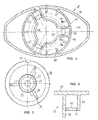
- the discharge device 11 shown in the drawing has a base body 12, which consists of plastic injection molding. It has a central elongated neck section 13, the shape and length of each Application is adapted. In the present case it is a so-called nose adapter, which is intended in one Nostril to be inserted into a patient. On his it has a discharge opening 14 in the form of an upper end Spray nozzle with an upstream angle chamber. To this is then inside the hollow nozzle section 13th a sleeve-shaped piston rod carrier 15 is provided in the a likewise hollow piston rod 16 is pressed in at the bottom. In it in turn is a piston tappet 17 in the form of one on it lower free end similar to beveled hollow steel needle an injection needle, by means of a Needle surrounding seal 18. This needle shaped plunger 17 completely penetrates the piston rod and is led up to the discharge opening 14, so its interior forms a discharge channel 19.
- the pharmaceutical medium 24 to be dispensed is in one Media container 20 provided as a cylindrical, below closed and open at the top, with side flange provided glass container formed like an ampoule is. It forms both the media storage and the Pump chamber 23 so that its inner walls simultaneously the Are cylinder barrel of a thrust piston pump 46.
- Your butt 21 is formed by a piston plug made of rubber or rubber-like material and one in the middle Membrane 22 in the form of a middle piece with a small wall thickness has, which are pierced by the piston tappet 17 can.
- the media container 20 is in an actuating and receiving sleeve 25 added, which is in the form of a very elongated plastic sleeve closed at the bottom with inner support ribs is designed for the media container.
- Your closed Bottom 26 forms an actuating surface for the Discharge device 11. It is between ribs 45 inside of the nozzle section together with the media container guided and axially movable therein.
- a first pressure point safety device 27 is formed on the outer circumference. It consists of three connecting bars or spokes 29 (Fig. 3), the material bridges 30 with a rotating outer ring 28 are connected. This is in one go a guide groove 42 with its circumferential position Outer circumference recorded in a snap connection 32, which in a cylindrical base section 34 of the base body, namely at its lower edge.
- the material bridges are designed so that when a break predetermined operating pressure (Fig. 2).
- a Inner rib 48 of the base section 34 places the ring 28 in its axial position.
- the base portion 34 extends from actuation shoulders 35 down, which as the total oval surface (Fig. 4) surrounded middle nozzle section 13 and down one have stiffening edge 36.
- the spokes 29 have lateral reinforcements and are in the axial direction Support ribs 31 stiffened.
- the outer surface of the actuator sleeve 25 has an outer handle in the form of a Corrugation on.
- Walls 44 are provided which protrude downwards. she form three arc sections 49 and then extend on both sides to the circumference of the base section outside so that they form slots 43 between them. Between whose walls 44 are platelets or webs 40 which a second pressure point safety device 39 for a second stroke form. They are over material bridges 41 with the walls connected. One of the walls 44 is extended and forms a rotary stop 38 on which one of the spokes 29 at one Rotation strikes.
- the one with the Medium 24 filled media container 20 is in the actuating sleeve 25 added and its pump chamber 23 is through the Piston plug 21 tightly closed. It is in one Distance from the tip of the piston rod 17 when the Actuating sleeve is in the starting position, this is defined that the ring 28 of the first pressure point securing 27 is engaged in the snap device 32 and on the Bottom of the ribs 48 abuts.
- the resulting ready-to-use discharge device is now seized by the user if necessary by using two Fingers on the actuation shoulders 35 and with the Presses thumb on the actuating surface 26.
- a sufficient actuation pressure tear the Material bridges 30, which form a predetermined breaking point, so that the actuating sleeve now with a predetermined force and accordingly high operating speed in Fig. 1 after is moved up.
- the piston rod 16 presses the piston plug in the media container 20 and the medium 24 is on the Discharge channel 19 in the needle and the outlet opening 14 as Spray released. This happens while the patient the neck portion 13 inserted into one of its nostrils would have.
- the spokes 29 lie on the Bars 40.
- the material bridges also break there for the second discharge stroke stage 41.
- the second discharge stroke level is also like that first run by the lower front edge of the piston rod 16 the piston plug 21 further into the media container 20 pushes in and thus the medium in the manner of a thrust piston pump through the discharge channel 19.
- this is the function completed. So it's a two-way disposable pump, which is disposed of after a single use. Because with one exception the media storage 20 and the steel needle 17, and possibly the Piston plug 21 all parts are made of plastic injection molding, preferably made of the same material recycling possible.
- the discharge device allows the individual partial batches dispense with great dosing accuracy and reliability; if desired in different sizes Amounts.
- the partial strokes are because of the first actuation to pass through empty paths different, what with the Design is taken into account. It is possible to use the discharge device to adapt for other purposes, for example for medication for eyes or other paired or multiple occurring application locations are determined. Also for several successive applications in the form of spray or other output form, for example the treatment in Intervals of a few minutes on the same application site, the device can be used.
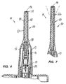
- the discharge device 11 corresponds to the one below explained differences of that according to FIGS. 1 to 5. On their description is referred to. Wear the same parts same reference numerals.
- the nozzle section 13 tapers towards its end and goes into an outlet trunk 50, which is integral with this is trained and elongated and thin. Its diameter is between 3 and 4 mm or less, however usually not more than 5 mm, and it is preferably over 10 mm between 20 and 30 mm long. The ratio trunk length to diameter is about 7 and should advantageously be over 5 be. It is circular cylindrical and has at its end the outlet opening 15 in the form of a spray nozzle. This is a hole of small diameter formed in the outlet trunk 50, that along with vertebral canals 51 that go into that front end of a filler 52 are formed, a Forms nozzle with conical spray.
- the filler 52 is integral with the piston rod 16 formed and has conduit channels 53 on its outside very small cross section in the form of molded longitudinal grooves.
- the longitudinal piece fills an inner channel 54 of the hollow one Exhaust nozzle 50 from what the dead space for the emerging Medium minimized.
- the line channels 53 are through one a reduction in the diameter of the filler / piston rod unit formed distribution chamber 53 to the inner bore of the needle 17 connected.
- the outlet nozzle 50 is flexible, namely in the area of an articulated kink 56, which in a middle area of the outlet trunk. It is through it formed that the filler 52a in the area of the kink in Diameter is reduced so much that it is due to the flexibility of its material is slightly flexible.
- the material too of the outlet proboscis is so flexible that it is a allows some hose-like bend. If necessary, could bellows-like folds are molded in there to facilitate bending his. It is also possible to remove the entire trunk through appropriate choice of materials elastic or plastic to make it pliable. It is also possible to use the outlet proboscis to constantly bend or bend or align choose the spray nozzle differently than in the axial direction.
Description
- Fig. 1
- einen Längsschnitt durch eine Austragvorrichtung,
- Fig. 2
- ein stark vergrößertes Detail des Bereiches II in Fig. 1,
- Fig. 3
- eine Ansicht der Betätigungshülse und des angeformten Ringes, in Fig. 1 gemäß Pfeil III von unten gesehen,
- Fig. 4
- einen Schnitt nach der Linie IV in Fig.1,
- Fig. 5
- einen Schnitt nach der Linie V in Fig. 4 und
- Fig. 6 und 7
- Teillängsschnitte durch Varianten einer Austragvorrichtung.
Claims (20)
- Austragvorrichtung für fließfähige Medien (24) mittels einer Schubkolbenpumpe (46), mit einem Grundkörper (12) und einem Medienspeicher (20), der die Pumpenkammer (23) der Schubkolbenpumpe (46) bildet und in dem ein Pumpenkolben (21) von einer Ausgangsstellung über wenigstens zwei Austragshub-Stufen bewegbar ist, während derer das Medium (24) über einen im Grundkörper (12) vorgesehenen Austragskanal (19) zu einer Austragsöffnung (14), insbesondere einer Sprühdüse, strömt, bei der in der Ausgangsstellung und am Beginn jeder weiteren Austragshub-Stufe eine durch eine aufzubringende Mindest-Betätigungskraft zerstörbare Druckpunktsicherung (27, 39) vorgesehen ist, dadurch gekennzeichnet, daß ein von der zerstörbaren Druckpunktsicherung gesonderter, fester Anschlag (37) zur Beendigung der ersten Austragshub-Stufe vorgesehen ist und die Druckpunktsicherung (39) für eine weitere Austragshub-Stufe durch eine den Anschlag (37) freigebende Entriegelungsbetätigung in Auslöseposition zu bringen ist.
- Austragvorrichtung nach Anspruch 1, dadurch gekennzeichnet, daß die Druckpunktsicherungen (27, 39) wenigstens eine Sollbruchstelle (30, 41) enthalten.
- Austragvorrichtung nach Anspruch 1 oder 2, dadurch gekennzeichnet, daß eine der Druckpunktsicherungen (27) einen einschnappbaren Ring (28) enthält, der vorzugsweise an einer einen Betätigungsdrücker bildenden, den Medienbehälter (20) aufnehmenden Hülse (25) über zerstörbare Materialbrücken (30, 41) angeformt ist.
- Austragvorrichtung nach Anspruch 3, dadurch gekennzeichnet, daß eines der den Anschlag bildenden Anschlagelemente (29) an den Ring (28) tragenden Speichen (29) ausgebildet ist.
- Austragvorrichtung nach Anspruch 3 und 4, dadurch gekennzeichnet, daß die den Anschlag bildenden Anschlagelemente (29) einseitig nach unten durch eine angeformte Rippe verstärkt werden.
- Austragvorrichtung nach einem der vorhergehenden Ansprüche, dadurch gekennzeichnet, daß die Entriegelungsbetätigung durch eine Drehung einer einen Betätigungsdrücker bildenden, den Medienbehälter (20) aufnehmenden Hülse (35) erfolgt.
- Austragvorrichtung nach einem der vorhergehenden Ansprüche, dadurch gekennzeichnet, daß die Druckpunktsicherung (39) für eine weitere Austragshubstufe als wenigstens ein, vorzugsweise drei, über Sollbruchstellen (41) mit dem Grundkörper verbundener Steg (40) ausgebildet ist, der insbesondere im Bereich eines von Wandungen (44) des Grundkörpers (12) begrenzten Schlitzes (43) angeordnet ist.
- Austragvorrichtung nach Anspruch 5 oder 6, dadurch gekennzeichnet, daß ein Drehanschlag (38) für die Entriegelungsbetätigung vorgesehen ist, der vorzugsweise durch eine vorspringende Wandung (44) des Grundkörpers (12) gebildet ist.
- Austragvorrichtung nach einem der Ansprüche 5 bis 7, gekennzeichnet durch eine Handhabe (33) für die Entriegelungsbetätigung, vorzugsweise eine Rifflung der aus dem Grundkörper (12) vorstehenden, einen Betätigungsdrücker bildenden, den Medienbehälter (20) aufnehmenden Hülse (35).
- Austragvorrichtung nach einem der vorhergehenden Ansprüche, dadurch gekennzeichnet, daß der Grundkörper (12) einen vorspringenden Stutzenabschnitt (13) mit der Austragöffnung (14) am Ende, von diesem seitlich vorspringende Betätigungsschultern (35) und einen im wesentlichen zylindrischen Basisabschnitt (34) aufweist, der, zusammen mit dem Stutzenabschnitt (13), den Medienspeicher (20) und die Druckpunktsicherungen (27, 39) aufnimmt und aus dem eine in den Grundkörper (12) hineindrückbare Betätigungshülse (25) herausragt.
- Austragvorrichtung nach einem der vorhergehenden Ansprüche, dadurch gekennzeichnet, daß der Medienspeicher (20) in seiner Ausgangsstellung dicht verschlossen, jedoch am Beginn einer weiteren Austragshubstufe mit dem Austragskanal (19) verbunden ist, wobei die Austragsvorrichtung (11) insbesondere als Einweg-Mehrfachzerstäuber, vorzugsweise als Einweg-Zweifach-Zerstäuber für die aufeinanderfolgende Verabreichung eines Medikaments in beide Nasenlöcher eines Patienten ausgebildet ist.
- Austragvorrichtung nach einem der vorhergehenden Ansprüche, dadurch gekennzeichnet, daß zur Betätigung der Schubkolbenpumpe (46) eine Kolbenstange (16) einen Verschluß des Medienspeichers (20) bildenden, zur Öffnung des Medienspeichers und zu seiner Verbindung mit dem Austragskanal (19) von einem hohlen Kolbenstößel (17), wie einer Hohlnadel, durchstechbaren Kolbenstopfen (21) als Pumpenkolben in den Medienspeicher (20) hineindrückt.
- Austragvorrichtung nach einem der vorhergehenden Ansprüche, dadurch gekennzeichnet, daß zwischen der Ausgangsstellung und der Stellung, in der der Medienspeicher (20) geöffnet wird, ein Leerhub vorhanden ist.
- Austragvorrichtung nach einem der vorhergehenden Ansprüche, dadurch gekennzeichnet, daß ein Grundkörper (12) der Austragvorrichtung (11) einen Stutzenabschnitt (13) aufweist; an den sich ein gegenüber dem Stutzenabschnitt (13) im Durchmesser erheblich reduzierter, dünner, langer Auslaßrüssel (50) anschließt, an dessen Ende die Auslaßöffnung (14), vorzugsweise in Form einer Sprühdüse, angeordnet ist.
- Austragvorrichtung nach Anspruch 14, dadurch gekennzeichnet, daß der Auslaßrüssel (50) einen Innenkanal (54) aufweist, der weitgehend, bis auf wenigstens einen Leitungskanal (53) für das Medium (24), von einem Füllstück (52) ausgefüllt ist, dessen die an die Auslaßöffnung (14) angrenzende Stirnseite vorzugsweise mit der Auslaßöffnung zur Abgrenzung von Sprühdüsen-Wirbelkanälen (51) zusammenwirkt und insbesondere diese enthält.
- Austragvorrichtung nach Ansprüche 14 oder 15, dadurch gekennzeichnet, daß der Auslaßrüssel (50) bei einer Länge von mehr als 10 mm, vorzugsweise zwischen 20 und 30 mm, einen Durchmesser unter 5 mm, vorzugsweise zwischen 3 und 4 mm, aufweist.
- Austragvorrichtung nach einem der Ansprüche 14 bis 16, dadurch gekennzeichnet, daß der Auslaßrüssel (50) eine Abwinklung, wie eine Krümmung oder einen Knick aufweist oder abgewinkelt von dem Stutzenabschnitt (13) abzweigt, wobei vorzugsweise die Abwinklung durch einen biegsamen, sich bei der Einführung in einen Nasenkanal selbst diesem anpassenden Abschnitt (56) des Auslaßrüssels (50) gebildet wird.
- Austragvorrichtung nach einem der Ansprüche 14 bis 17, dadurch gekennzeichnet, daß der Auslaßrüssel (50) zur Einführung in einen Nasenkanal insbesondere dem inneren Nasenloch ausgebildet ist und/oder zur Ausbringung eines Medikaments, vorzugsweise eines Impf- bzw. Immunisierungsmittels gegen Erkältungskrankheiten, wie Grippe, ausgebildet ist.
- Austragvorrichtung nach einem Ansprüche 14 bis 18, dadurch gekennzeichnet, daß die Auslaßöffnung (14) zur Erzeugung eines Sprühstrahls zur Benetzung der Nasenmuscheln (conchae nasi) ausgebildet ist.
- Austragvorrichtung nach einem der Ansprüche 14 bis 19, dadurch gekennzeichnet, daß der Stutzenabschnitt (13) einen Kolbenstößel (16) und einen Führungskanal für einen Pumpenzylinder bildenden Medienbehälter (20) enthält.
Priority Applications (2)
| Application Number | Priority Date | Filing Date | Title |
|---|---|---|---|
| DE29824620U DE29824620U1 (de) | 1997-01-09 | 1998-01-08 | Austragvorrichtung für fließfähige Medien mittels einer Schubkolbenpumpe |
| EP02007105A EP1219356B1 (de) | 1997-01-09 | 1998-01-08 | Austragvorrichtung für fliessfähige Medien mittels einer Schubkolbenpumpe |
Applications Claiming Priority (5)
| Application Number | Priority Date | Filing Date | Title |
|---|---|---|---|
| DE19700437A DE19700437B4 (de) | 1996-01-23 | 1997-01-09 | Austragvorrichtung für fließfähige Medien mittels einer Schubkolbenpumpe |
| DE19700437 | 1997-01-09 | ||
| DE19723133A DE19723133A1 (de) | 1997-06-03 | 1997-06-03 | Austragvorrichtung für Medien |
| DE19723133 | 1997-06-03 | ||
| PCT/EP1998/000061 WO1998030335A1 (de) | 1997-01-09 | 1998-01-08 | Austragvorrichtung für fliessfähige medien mittels einer schubkolbenpumpe |
Related Child Applications (2)
| Application Number | Title | Priority Date | Filing Date |
|---|---|---|---|
| EP02007105A Division EP1219356B1 (de) | 1997-01-09 | 1998-01-08 | Austragvorrichtung für fliessfähige Medien mittels einer Schubkolbenpumpe |
| EP02007105.6 Division-Into | 2002-03-28 |
Publications (2)
| Publication Number | Publication Date |
|---|---|
| EP0951362A1 EP0951362A1 (de) | 1999-10-27 |
| EP0951362B1 true EP0951362B1 (de) | 2002-06-19 |
Family
ID=7831207
Family Applications (3)
| Application Number | Title | Priority Date | Filing Date |
|---|---|---|---|
| EP02007105A Expired - Lifetime EP1219356B1 (de) | 1997-01-09 | 1998-01-08 | Austragvorrichtung für fliessfähige Medien mittels einer Schubkolbenpumpe |
| EP98904040A Expired - Lifetime EP0951362B1 (de) | 1997-01-09 | 1998-01-08 | Austragvorrichtung für fliessfähige medien mittels einer schubkolbenpumpe |
| EP98109321A Expired - Lifetime EP0882516B1 (de) | 1997-06-03 | 1998-05-22 | Spender für Medien |
Family Applications Before (1)
| Application Number | Title | Priority Date | Filing Date |
|---|---|---|---|
| EP02007105A Expired - Lifetime EP1219356B1 (de) | 1997-01-09 | 1998-01-08 | Austragvorrichtung für fliessfähige Medien mittels einer Schubkolbenpumpe |
Family Applications After (1)
| Application Number | Title | Priority Date | Filing Date |
|---|---|---|---|
| EP98109321A Expired - Lifetime EP0882516B1 (de) | 1997-06-03 | 1998-05-22 | Spender für Medien |
Country Status (14)
| Country | Link |
|---|---|
| US (2) | US6321942B1 (de) |
| EP (3) | EP1219356B1 (de) |
| JP (2) | JP4046769B2 (de) |
| KR (2) | KR100492350B1 (de) |
| CN (1) | CN1103642C (de) |
| AT (3) | ATE475487T1 (de) |
| AU (2) | AU734535B2 (de) |
| BR (2) | BR9807065A (de) |
| CA (1) | CA2277208C (de) |
| DE (5) | DE19723133A1 (de) |
| DK (2) | DK0951362T3 (de) |
| ES (1) | ES2176960T3 (de) |
| PT (1) | PT951362E (de) |
| WO (1) | WO1998030335A1 (de) |
Families Citing this family (59)
| Publication number | Priority date | Publication date | Assignee | Title |
|---|---|---|---|---|
| GB2316451B (en) * | 1996-08-15 | 2000-09-13 | Tenax Corp | Dispensing device |
| FR2764807B1 (fr) * | 1997-06-18 | 1999-08-20 | Valois Sa | Dispositif de distribution nasale d'un produit fluide ou pulverulent |
| ATE390960T1 (de) * | 1999-02-14 | 2008-04-15 | Pfeiffer Erich Gmbh & Co Kg | Spender für fliessfähige medien |
| DE19940236A1 (de) | 1999-08-25 | 2001-03-08 | Pfeiffer Erich Gmbh & Co Kg | Spender mit manuell betätigbarer Ausbringeinrichtung |
| DE19944209A1 (de) * | 1999-09-15 | 2001-03-22 | Pfeiffer Erich Gmbh & Co Kg | Spender zum ggf. zerstäubten Ausbringen eines insbesondere flüssigen Mediums aus einem Behältnis |
| DE19944211A1 (de) | 1999-09-15 | 2001-03-22 | Pfeiffer Erich Gmbh & Co Kg | Vorrichtung zum ggf. zerstäubten Ausbringen eines insbesondere flüssigen Mediums |
| US6382204B1 (en) * | 1999-10-14 | 2002-05-07 | Becton Dickinson And Company | Drug delivery system including holder and drug container |
| DE10036594A1 (de) * | 2000-07-27 | 2002-02-07 | Pfeiffer Erich Gmbh & Co Kg | Austragvorrichtung für Medien |
| GB2372782B (en) * | 2000-09-29 | 2004-09-22 | Pharmacure Ab | Nasal sprays |
| JP4911867B2 (ja) * | 2001-04-10 | 2012-04-04 | ベクトン・ディキンソン・アンド・カンパニー | ホルダ及び薬剤容器を含む薬剤送出システム |
| AU2002333785A1 (en) * | 2002-09-03 | 2004-03-29 | Pharmacure Health Care Ab | Nasal sprays |
| US20080220107A1 (en) * | 2002-09-03 | 2008-09-11 | Pharmacure Health Care Ab | Nasal spray apparatus |
| JP4259157B2 (ja) * | 2003-03-25 | 2009-04-30 | オムロンヘルスケア株式会社 | 液体アンプル容器 |
| GB0309354D0 (en) * | 2003-04-24 | 2003-06-04 | Glaxo Group Ltd | Nozzle for a nasal inhaler |
| DE10321902A1 (de) * | 2003-05-06 | 2004-12-09 | Ing. Erich Pfeiffer Gmbh | Austragvorrichtung für zumindest ein Medium |
| DE10323603A1 (de) * | 2003-05-20 | 2004-12-30 | Ing. Erich Pfeiffer Gmbh | Dosiervorrichtung mit einer Pumpeinrichtung |
| US7188750B2 (en) * | 2003-09-05 | 2007-03-13 | Hospira, Inc. | Blow fill sealed container with twist off top operated by overcap and method of forming the same |
| US8499721B2 (en) * | 2003-11-06 | 2013-08-06 | Nova-Tech Engineering, Inc. | Apparatus and method for nasal delivery of compositions to birds |
| DE102004020152A1 (de) * | 2004-04-24 | 2005-11-10 | Hagin Susanne El | Dosierpumpenanordnung und Verfahren zu ihrer Herstellung |
| ES2245251B1 (es) * | 2004-06-15 | 2006-08-01 | Saint-Gobain Calmar S.A. | Componente de dispensador de fluidos, procedimiento para su fabricacion y dispensador correspondiente. |
| GB0416801D0 (en) * | 2004-07-28 | 2004-09-01 | Reckitt Benckiser Uk Ltd | Apparatus and method of using the same |
| EP1693115B1 (de) * | 2005-02-22 | 2008-01-09 | Ing. Erich Pfeiffer GmbH | Spender für Medien sowie Montageverfahren hierfür |
| US20070212307A1 (en) * | 2006-02-10 | 2007-09-13 | Daniel Wermeling | Pharmaceutical Compositions Comprising an Opioid Receptor Antagonist and Methods of Using Same |
| GB2441129B (en) | 2006-08-26 | 2008-11-26 | Norwich Pharma Technologies Ltd | Dosage Dispensing Canister |
| JP2010515541A (ja) | 2007-01-09 | 2010-05-13 | ミスティック ファーマシューティカルズ, インコーポレイテッド | 経鼻カートリッジデバイス |
| CA2688689C (en) | 2007-05-16 | 2015-06-30 | Mystic Pharmaceuticals, Inc. | Combination unit dose dispensing containers |
| US8683995B2 (en) | 2007-05-16 | 2014-04-01 | Mystic Pharmaceuticals, Inc. | Dose dispensing containers |
| US9248076B2 (en) | 2007-05-16 | 2016-02-02 | Mystic Pharmaceuticals, Inc. | Dose dispensing containers |
| CN103707452B (zh) | 2007-09-14 | 2017-05-03 | 神秘制药公司 | 深冲压容器形成方法 |
| PT2381923T (pt) | 2008-12-22 | 2018-11-13 | Serenity Pharmaceuticals Llc | Administração intranasal de desmopressina |
| WO2010075327A1 (en) * | 2008-12-22 | 2010-07-01 | Serenity Pharmaceuticals Corporation | Desmopressin composition |
| KR101792696B1 (ko) | 2009-06-18 | 2017-11-02 | 알레간 인코포레이티드 | 안전한 데스모프레신 투여 |
| DE102009037164B3 (de) | 2009-08-03 | 2010-12-09 | Ing. Erich Pfeiffer Gmbh | Austragvorrichtung für flüssige Medien |
| DE102010013543B3 (de) * | 2010-03-26 | 2011-06-30 | Ing. Erich Pfeiffer GmbH, 78315 | Austragvorrichtung für Flüssigkeiten |
| US8627816B2 (en) | 2011-02-28 | 2014-01-14 | Intelliject, Inc. | Medicament delivery device for administration of opioid antagonists including formulations for naloxone |
| US8939943B2 (en) | 2011-01-26 | 2015-01-27 | Kaleo, Inc. | Medicament delivery device for administration of opioid antagonists including formulations for naloxone |
| GB2489216B (en) | 2011-03-16 | 2013-08-07 | Consort Medical Plc | Fluid delivery device |
| GB201117518D0 (en) | 2011-10-11 | 2011-11-23 | Consort Medical Plc | Fluid delivery device |
| SG11201507347QA (en) | 2013-03-15 | 2015-10-29 | Janssen Pharmaceutica Nv | Pharmaceutical composition of s-ketamine hydrochloride |
| GB2516434B (en) | 2013-07-19 | 2015-11-25 | Consort Medical Plc | Fluid delivery device |
| DE102013220492A1 (de) * | 2013-10-10 | 2015-04-16 | Aptar Radolfzell Gmbh | Kindergesicherte Austragvorrichtung |
| FR3023189B1 (fr) * | 2014-07-04 | 2021-03-26 | Aptar France Sas | Dispositif de distribution de produit fluide. |
| FR3023188B1 (fr) * | 2014-07-04 | 2016-08-19 | Aptar France Sas | Dispositif de distribution de produit fluide. |
| US9517307B2 (en) | 2014-07-18 | 2016-12-13 | Kaleo, Inc. | Devices and methods for delivering opioid antagonists including formulations for naloxone |
| MA40620A (fr) | 2014-09-15 | 2016-03-24 | Janssen Pharmaceutica Nv | Régimes posologiques spécifiques au génotype val66met (snp rs6265) et méthodes pour le traitement de la dépression |
| EP3097986A1 (de) | 2015-05-29 | 2016-11-30 | Sulzer Mixpac AG | Applikator für einen flüssigen inhaltsstoff und verfahren zur aktivierung eines applikators |
| FR3050984B1 (fr) * | 2016-05-04 | 2020-05-15 | Aptar France Sas | Dispositif de distribution de produit fluide. |
| FR3052690B1 (fr) * | 2016-06-20 | 2018-06-22 | Aptar France Sas | Dispositif de distribution de produit fluide. |
| AU2017379094B2 (en) | 2016-12-23 | 2023-08-24 | Kaleo, Inc. | Medicament delivery device and methods for delivering drugs to infants and children |
| FR3075650B1 (fr) * | 2017-12-22 | 2020-01-03 | Aptar France Sas | Dispositif de distribution de produit fluide. |
| RU2020123893A (ru) | 2017-12-22 | 2022-01-24 | Янссен Фармасьютикалз, Инк. | Эскетамин для лечения депрессии |
| CN114126595A (zh) | 2019-03-05 | 2022-03-01 | 杨森制药公司 | 用于治疗抑郁症的艾司氯胺酮 |
| FR3098420B1 (fr) * | 2019-07-10 | 2021-07-09 | Aptar France Sas | Dispositif de distribution nasale de poudre |
| WO2021084114A1 (en) | 2019-11-01 | 2021-05-06 | Janssen Pharmaceutica, N.V. | Training devices and methods for simulating intranasal drug delivery |
| US11607216B2 (en) | 2020-05-06 | 2023-03-21 | Janssen Pharmaceuticals, Inc. | Adaptive responses from smart packaging of drug delivery absorbable adjuncts |
| KR20230018448A (ko) | 2020-05-28 | 2023-02-07 | 얀센 파마슈티카 엔.브이. | 우울증의 치료 방법 |
| EP4208227A1 (de) | 2020-09-01 | 2023-07-12 | Janssen Pharmaceutica NV | Arzneimittelabgabevorrichtungen mit einem mehrfachabgabekopf |
| WO2023131922A1 (en) | 2022-01-10 | 2023-07-13 | Janssen Pharmaceuticals, Inc. | Compositions and methods for the treatment of depression |
| WO2023131921A1 (en) | 2022-01-10 | 2023-07-13 | Janssen Pharmaceuticals, Inc. | Compositions and methods for the treatment of depression |
Family Cites Families (33)
| Publication number | Priority date | Publication date | Assignee | Title |
|---|---|---|---|---|
| US3133A (en) * | 1843-06-14 | Manner of | ||
| US3403823A (en) * | 1966-10-03 | 1968-10-01 | Valve Corp Of America | Tamper-proof actuator cap |
| US3845763A (en) | 1973-02-28 | 1974-11-05 | Nasco Plastics Inc | Syringe with puncturable stem |
| US4046495A (en) * | 1976-09-30 | 1977-09-06 | Grimm Jr Bruce F | Dispenser pump |
| US4162030A (en) * | 1977-04-20 | 1979-07-24 | J. Claybrook Lewis and Associates, Ltd. | Disposable package dispenser having a pressure release channel |
| US4162746A (en) | 1977-06-22 | 1979-07-31 | Diamond International Corporation | Liquid dispenser locking means |
| US4234127A (en) | 1978-02-01 | 1980-11-18 | Canyon Corporation | Manually operated sprayer |
| US4189064A (en) * | 1978-06-01 | 1980-02-19 | Diamond International Corporation | Pumps sprayer |
| FI59637C (fi) * | 1979-11-20 | 1981-09-10 | Valmet Oy | Anordning i torkpartiet av en pappersmaskin |
| US4375266A (en) * | 1980-11-18 | 1983-03-01 | Realex Corporation | Down-locking dispensing pump with side-orificed, product-mixing ball hold-down |
| US4420101A (en) * | 1981-11-18 | 1983-12-13 | Diamond International Corp. | Squeeze bottle with self-venting dispensing closure |
| DE3517558A1 (de) * | 1985-05-15 | 1986-11-20 | Ing. Erich Pfeiffer GmbH & Co KG, 7760 Radolfzell | Handbetaetigte ausgabeeinrichtung fuer medien |
| US4767416A (en) | 1986-12-01 | 1988-08-30 | Johnson & Johnson Patient Care, Inc. | Spray nozzle for syringe |
| US4964069A (en) | 1987-05-12 | 1990-10-16 | International Business Machines Corporation | Self adjusting video interface |
| DE3734306A1 (de) | 1987-10-10 | 1989-04-27 | Pfeiffer Erich Gmbh & Co Kg | Austragvorrichtung fuer fliessfaehige medien |
| DE8906136U1 (de) * | 1988-02-05 | 1989-07-20 | Stella Kg Werner Deussen, 6228 Eltville, De | |
| DE68909310T2 (de) * | 1988-06-02 | 1994-03-24 | Tech De Pulverisation Step Par | Vordruck Dosierpumpe mit verbessertem Ansaugverhalten. |
| US5092854A (en) * | 1989-11-13 | 1992-03-03 | Johnson & Johnson Medical, Inc. | Two-part flexible swivel spray tip for syringe |
| WO1991009683A1 (en) * | 1989-12-28 | 1991-07-11 | Yoshino Kogyosho Co., Ltd. | Liquid sprayer |
| DE4008068A1 (de) | 1990-03-14 | 1991-09-19 | Pfeiffer Erich Gmbh & Co Kg | Austragvorrichtung fuer medien |
| DE4021263C2 (de) | 1990-07-04 | 1996-04-11 | Pfeiffer Erich Gmbh & Co Kg | Austragvorrichtung für Medien |
| US5158211A (en) | 1990-08-30 | 1992-10-27 | Philip Meshberg | Fluid dispensing unit retainer |
| JPH06508549A (ja) * | 1991-06-26 | 1994-09-29 | バロワ (ソシエテ アノニム) | 所定量の流体を噴霧する装置及び該装置を充填する方法 |
| IT1253173B (it) * | 1991-08-02 | 1995-07-10 | Rosaria Galli | Contenitore-nebulizzatore endonasale avente incorporato un dispositivodi servoerogazione atto ad assicurare la efficace somministrazione in due tempi. |
| TW219953B (de) | 1991-09-30 | 1994-02-01 | Ppg Industries Inc | |
| GB9125699D0 (en) | 1991-12-03 | 1992-01-29 | Glaxo Group Ltd | Device |
| DE29601047U1 (de) * | 1995-02-09 | 1996-06-13 | Pfeiffer Erich Gmbh & Co Kg | Austragvorrichtung für fließfähige Medien, insbesondere für den Austrag in nur einem Hub |
| DE4412041A1 (de) * | 1994-04-08 | 1995-10-12 | Pfeiffer Erich Gmbh & Co Kg | Austragvorrichtung für fließfähige Medien, insbesondere für den Austrag in nur einem Hub |
| GB9408276D0 (en) | 1994-04-26 | 1994-06-15 | Bespak Plc | Dispensing pump |
| DE19509247C2 (de) | 1994-06-07 | 2001-05-17 | Manfred E Wenner | Geber zur kontinuierlichen, dosierten Abgabe einer Flüssigkeit |
| DE4441263A1 (de) * | 1994-11-19 | 1996-05-23 | Caideil M P Teoranta Tormakead | Austragvorrichtung für Medien |
| JP3776125B2 (ja) * | 1995-02-09 | 2006-05-17 | インジ エリッヒ プファイファ ゲーエムベーハ | 流動性媒体の吐出装置 |
| US5560520A (en) * | 1995-08-07 | 1996-10-01 | Calmar Inc. | Precompression pump sprayer |
-
1997
- 1997-06-03 DE DE19723133A patent/DE19723133A1/de not_active Withdrawn
-
1998
- 1998-01-08 WO PCT/EP1998/000061 patent/WO1998030335A1/de active IP Right Grant
- 1998-01-08 EP EP02007105A patent/EP1219356B1/de not_active Expired - Lifetime
- 1998-01-08 AU AU62075/98A patent/AU734535B2/en not_active Ceased
- 1998-01-08 AT AT02007105T patent/ATE475487T1/de not_active IP Right Cessation
- 1998-01-08 DE DE59804505T patent/DE59804505D1/de not_active Expired - Lifetime
- 1998-01-08 CA CA002277208A patent/CA2277208C/en not_active Expired - Fee Related
- 1998-01-08 JP JP53053898A patent/JP4046769B2/ja not_active Expired - Fee Related
- 1998-01-08 DE DE29824620U patent/DE29824620U1/de not_active Expired - Lifetime
- 1998-01-08 DE DE59814459T patent/DE59814459D1/de not_active Expired - Lifetime
- 1998-01-08 BR BR9807065-7A patent/BR9807065A/pt not_active IP Right Cessation
- 1998-01-08 EP EP98904040A patent/EP0951362B1/de not_active Expired - Lifetime
- 1998-01-08 CN CN98803216A patent/CN1103642C/zh not_active Expired - Fee Related
- 1998-01-08 ES ES98904040T patent/ES2176960T3/es not_active Expired - Lifetime
- 1998-01-08 PT PT98904040T patent/PT951362E/pt unknown
- 1998-01-08 DK DK98904040T patent/DK0951362T3/da active
- 1998-01-08 KR KR10-1999-7006158A patent/KR100492350B1/ko not_active IP Right Cessation
- 1998-01-08 US US09/341,336 patent/US6321942B1/en not_active Expired - Lifetime
- 1998-01-08 AT AT98904040T patent/ATE219391T1/de not_active IP Right Cessation
- 1998-05-22 DK DK98109321T patent/DK0882516T3/da active
- 1998-05-22 DE DE59812015T patent/DE59812015D1/de not_active Expired - Lifetime
- 1998-05-22 EP EP98109321A patent/EP0882516B1/de not_active Expired - Lifetime
- 1998-05-22 AT AT98109321T patent/ATE277689T1/de not_active IP Right Cessation
- 1998-06-02 US US09/089,753 patent/US6059150A/en not_active Expired - Lifetime
- 1998-06-02 KR KR1019980020464A patent/KR100559101B1/ko not_active IP Right Cessation
- 1998-06-02 BR BR9801755A patent/BR9801755A/pt not_active IP Right Cessation
- 1998-06-03 JP JP10169157A patent/JPH10338298A/ja active Pending
- 1998-06-03 AU AU69874/98A patent/AU740121B2/en not_active Ceased
Also Published As
Similar Documents
| Publication | Publication Date | Title |
|---|---|---|
| EP0951362B1 (de) | Austragvorrichtung für fliessfähige medien mittels einer schubkolbenpumpe | |
| DE60029556T2 (de) | System zur Verabreichung von Arzneimittlen mit einem Arzneimittelbehälter und dessen Halterung | |
| EP1297898B1 (de) | Spender mit Perforationsnadel für beim Austragen zu mischende Medien | |
| EP1084765B1 (de) | Vorrichtung zum ggf. zerstäubten Ausbringen eines insbesondere flüssigen Mediums | |
| EP1071517B1 (de) | Spender für fliessfähige medien | |
| DE19704849B4 (de) | Austragvorrichtung für Medien | |
| EP0648510B1 (de) | Spritzenvorrichtung zur Aufbewahrung und Applikation eines Mehrkomponentenmaterials sowie Herstellungsverfahren | |
| EP1536894B1 (de) | Apparat zum ausbringen von fluessigkeiten, hierzu geeignete behaelterpatrone, und system aus dem apparat zum ausbringen von fluessigkeiten und der behaelterpatrone | |
| EP2252350B1 (de) | Verabreichungsvorrichtung mit blockierbarem betätigungselement | |
| EP1051262B1 (de) | Manuell betätigbarer spender und schutzkappe mit blockiermitteln zum blockieren der betätigung | |
| DE60007593T2 (de) | Nasales Verabreichungsgerät mit Zerstäuberdüse | |
| DE19700437B4 (de) | Austragvorrichtung für fließfähige Medien mittels einer Schubkolbenpumpe | |
| EP1078694B1 (de) | Spender mit manuell betätigbarer Ausbringeinrichtung | |
| EP1742689B1 (de) | Vorrichtung zur verabreichung eines injizierbaren produkts mit gesicherter dosiereinrichtung | |
| EP1479450A2 (de) | Dosiervorrichtung mit einer Einhub-Pumpeinrichtung | |
| DE4412041A1 (de) | Austragvorrichtung für fließfähige Medien, insbesondere für den Austrag in nur einem Hub | |
| EP2300081A1 (de) | Ampulle mit ampullenhalterung | |
| EP2680910B1 (de) | Vorrichtung zur betätigung einer karpule | |
| EP1186312A2 (de) | Austragsvorrichtung für Medien | |
| WO2002087777A1 (de) | Vorrichtung zum versprühen von flüssigkeiten | |
| WO2009143640A1 (de) | Abmischvorrichtung für eine zweikammerampulle | |
| EP0438453A1 (de) | Injektionsvorrichtung mit originalitätssicherungsvorrichtung. | |
| EP0782866B1 (de) | Austragkopf für Medien, insbesondere zur medikamentösen Behandlung des Rachens | |
| WO1997010017A1 (de) | Gerät zur dosierten, luftgetragenen ausgabe von substanzen | |
| EP4008380A1 (de) | Medizinische spritze |
Legal Events
| Date | Code | Title | Description |
|---|---|---|---|
| PUAI | Public reference made under article 153(3) epc to a published international application that has entered the european phase |
Free format text: ORIGINAL CODE: 0009012 |
|
| 17P | Request for examination filed |
Effective date: 19990702 |
|
| AK | Designated contracting states |
Kind code of ref document: A1 Designated state(s): AT BE CH DE DK ES FI FR GB GR IE IT LI NL PT SE |
|
| GRAG | Despatch of communication of intention to grant |
Free format text: ORIGINAL CODE: EPIDOS AGRA |
|
| 17Q | First examination report despatched |
Effective date: 20011128 |
|
| GRAG | Despatch of communication of intention to grant |
Free format text: ORIGINAL CODE: EPIDOS AGRA |
|
| GRAH | Despatch of communication of intention to grant a patent |
Free format text: ORIGINAL CODE: EPIDOS IGRA |
|
| GRAH | Despatch of communication of intention to grant a patent |
Free format text: ORIGINAL CODE: EPIDOS IGRA |
|
| GRAA | (expected) grant |
Free format text: ORIGINAL CODE: 0009210 |
|
| AK | Designated contracting states |
Kind code of ref document: B1 Designated state(s): AT BE CH DE DK ES FI FR GB GR IE IT LI NL PT SE |
|
| REF | Corresponds to: |
Ref document number: 219391 Country of ref document: AT Date of ref document: 20020715 Kind code of ref document: T |
|
| REG | Reference to a national code |
Ref country code: GB Ref legal event code: FG4D Free format text: NOT ENGLISH |
|
| REG | Reference to a national code |
Ref country code: CH Ref legal event code: NV Representative=s name: ZIMMERLI, WAGNER & PARTNER AG Ref country code: CH Ref legal event code: EP |
|
| GBT | Gb: translation of ep patent filed (gb section 77(6)(a)/1977) |
Effective date: 20020619 |
|
| REG | Reference to a national code |
Ref country code: DK Ref legal event code: T3 |
|
| REG | Reference to a national code |
Ref country code: IE Ref legal event code: FG4D Free format text: GERMAN |
|
| REF | Corresponds to: |
Ref document number: 59804505 Country of ref document: DE Date of ref document: 20020725 |
|
| REG | Reference to a national code |
Ref country code: GR Ref legal event code: EP Ref document number: 20020403121 Country of ref document: GR |
|
| REG | Reference to a national code |
Ref country code: PT Ref legal event code: SC4A Free format text: AVAILABILITY OF NATIONAL TRANSLATION Effective date: 20020918 |
|
| REG | Reference to a national code |
Ref country code: ES Ref legal event code: FG2A Ref document number: 2176960 Country of ref document: ES Kind code of ref document: T3 |
|
| ET | Fr: translation filed | ||
| PLBE | No opposition filed within time limit |
Free format text: ORIGINAL CODE: 0009261 |
|
| STAA | Information on the status of an ep patent application or granted ep patent |
Free format text: STATUS: NO OPPOSITION FILED WITHIN TIME LIMIT |
|
| 26N | No opposition filed |
Effective date: 20030320 |
|
| PGFP | Annual fee paid to national office [announced via postgrant information from national office to epo] |
Ref country code: PT Payment date: 20061229 Year of fee payment: 10 |
|
| PGFP | Annual fee paid to national office [announced via postgrant information from national office to epo] |
Ref country code: FI Payment date: 20070119 Year of fee payment: 10 |
|
| PGFP | Annual fee paid to national office [announced via postgrant information from national office to epo] |
Ref country code: AT Payment date: 20070123 Year of fee payment: 10 Ref country code: DK Payment date: 20070123 Year of fee payment: 10 |
|
| PGFP | Annual fee paid to national office [announced via postgrant information from national office to epo] |
Ref country code: SE Payment date: 20070124 Year of fee payment: 10 |
|
| PGFP | Annual fee paid to national office [announced via postgrant information from national office to epo] |
Ref country code: IE Payment date: 20070126 Year of fee payment: 10 |
|
| PGFP | Annual fee paid to national office [announced via postgrant information from national office to epo] |
Ref country code: GR Payment date: 20070123 Year of fee payment: 10 |
|
| REG | Reference to a national code |
Ref country code: PT Ref legal event code: MM4A Free format text: LAPSE DUE TO NON-PAYMENT OF FEES Effective date: 20080708 |
|
| REG | Reference to a national code |
Ref country code: DK Ref legal event code: EBP |
|
| EUG | Se: european patent has lapsed | ||
| REG | Reference to a national code |
Ref country code: IE Ref legal event code: MM4A |
|
| PG25 | Lapsed in a contracting state [announced via postgrant information from national office to epo] |
Ref country code: PT Free format text: LAPSE BECAUSE OF NON-PAYMENT OF DUE FEES Effective date: 20080708 Ref country code: FI Free format text: LAPSE BECAUSE OF NON-PAYMENT OF DUE FEES Effective date: 20080108 |
|
| PG25 | Lapsed in a contracting state [announced via postgrant information from national office to epo] |
Ref country code: AT Free format text: LAPSE BECAUSE OF NON-PAYMENT OF DUE FEES Effective date: 20080108 |
|
| PG25 | Lapsed in a contracting state [announced via postgrant information from national office to epo] |
Ref country code: SE Free format text: LAPSE BECAUSE OF NON-PAYMENT OF DUE FEES Effective date: 20080109 Ref country code: IE Free format text: LAPSE BECAUSE OF NON-PAYMENT OF DUE FEES Effective date: 20080108 Ref country code: DK Free format text: LAPSE BECAUSE OF NON-PAYMENT OF DUE FEES Effective date: 20080131 |
|
| PG25 | Lapsed in a contracting state [announced via postgrant information from national office to epo] |
Ref country code: GR Free format text: LAPSE BECAUSE OF NON-PAYMENT OF DUE FEES Effective date: 20080804 |
|
| REG | Reference to a national code |
Ref country code: CH Ref legal event code: PFA Owner name: ING. ERICH PFEIFFER GMBH Free format text: ING. ERICH PFEIFFER GMBH#OESCHLESTRASSE 124-126#78315 RADOLFZELL (DE) -TRANSFER TO- ING. ERICH PFEIFFER GMBH#OESCHLESTRASSE 124-126#78315 RADOLFZELL (DE) |
|
| PGFP | Annual fee paid to national office [announced via postgrant information from national office to epo] |
Ref country code: NL Payment date: 20110119 Year of fee payment: 14 |
|
| PGFP | Annual fee paid to national office [announced via postgrant information from national office to epo] |
Ref country code: ES Payment date: 20110121 Year of fee payment: 14 |
|
| PGFP | Annual fee paid to national office [announced via postgrant information from national office to epo] |
Ref country code: CH Payment date: 20120124 Year of fee payment: 15 |
|
| PGFP | Annual fee paid to national office [announced via postgrant information from national office to epo] |
Ref country code: BE Payment date: 20120123 Year of fee payment: 15 |
|
| REG | Reference to a national code |
Ref country code: NL Ref legal event code: V1 Effective date: 20120801 |
|
| REG | Reference to a national code |
Ref country code: DE Ref legal event code: R082 Ref document number: 59804505 Country of ref document: DE Representative=s name: PATENTANWAELTE RUFF, WILHELM, BEIER, DAUSTER &, DE Effective date: 20121025 Ref country code: DE Ref legal event code: R081 Ref document number: 59804505 Country of ref document: DE Owner name: APTAR RADOLFZELL GMBH, DE Free format text: FORMER OWNER: ING. ERICH PFEIFFER GMBH, 78315 RADOLFZELL, DE Effective date: 20121025 |
|
| PG25 | Lapsed in a contracting state [announced via postgrant information from national office to epo] |
Ref country code: NL Free format text: LAPSE BECAUSE OF NON-PAYMENT OF DUE FEES Effective date: 20120801 |
|
| REG | Reference to a national code |
Ref country code: ES Ref legal event code: FD2A Effective date: 20130708 |
|
| BERE | Be: lapsed |
Owner name: ERICH *PFEIFFER G.M.B.H. Effective date: 20130131 |
|
| PG25 | Lapsed in a contracting state [announced via postgrant information from national office to epo] |
Ref country code: ES Free format text: LAPSE BECAUSE OF NON-PAYMENT OF DUE FEES Effective date: 20120109 |
|
| REG | Reference to a national code |
Ref country code: CH Ref legal event code: PL |
|
| PG25 | Lapsed in a contracting state [announced via postgrant information from national office to epo] |
Ref country code: BE Free format text: LAPSE BECAUSE OF NON-PAYMENT OF DUE FEES Effective date: 20130131 Ref country code: LI Free format text: LAPSE BECAUSE OF NON-PAYMENT OF DUE FEES Effective date: 20130131 Ref country code: CH Free format text: LAPSE BECAUSE OF NON-PAYMENT OF DUE FEES Effective date: 20130131 |
|
| REG | Reference to a national code |
Ref country code: FR Ref legal event code: PLFP Year of fee payment: 18 |
|
| PGFP | Annual fee paid to national office [announced via postgrant information from national office to epo] |
Ref country code: DE Payment date: 20150127 Year of fee payment: 18 Ref country code: IT Payment date: 20150123 Year of fee payment: 18 |
|
| PGFP | Annual fee paid to national office [announced via postgrant information from national office to epo] |
Ref country code: FR Payment date: 20150115 Year of fee payment: 18 Ref country code: GB Payment date: 20150123 Year of fee payment: 18 |
|
| REG | Reference to a national code |
Ref country code: DE Ref legal event code: R119 Ref document number: 59804505 Country of ref document: DE |
|
| GBPC | Gb: european patent ceased through non-payment of renewal fee |
Effective date: 20160108 |
|
| REG | Reference to a national code |
Ref country code: FR Ref legal event code: ST Effective date: 20160930 |
|
| PG25 | Lapsed in a contracting state [announced via postgrant information from national office to epo] |
Ref country code: DE Free format text: LAPSE BECAUSE OF NON-PAYMENT OF DUE FEES Effective date: 20160802 Ref country code: GB Free format text: LAPSE BECAUSE OF NON-PAYMENT OF DUE FEES Effective date: 20160108 |
|
| PG25 | Lapsed in a contracting state [announced via postgrant information from national office to epo] |
Ref country code: FR Free format text: LAPSE BECAUSE OF NON-PAYMENT OF DUE FEES Effective date: 20160201 |
|
| PG25 | Lapsed in a contracting state [announced via postgrant information from national office to epo] |
Ref country code: IT Free format text: LAPSE BECAUSE OF NON-PAYMENT OF DUE FEES Effective date: 20160108 |