EP0949071B1 - Zusatzeinrichtung für ein Druckwerk - Google Patents
Zusatzeinrichtung für ein Druckwerk Download PDFInfo
- Publication number
- EP0949071B1 EP0949071B1 EP99105615A EP99105615A EP0949071B1 EP 0949071 B1 EP0949071 B1 EP 0949071B1 EP 99105615 A EP99105615 A EP 99105615A EP 99105615 A EP99105615 A EP 99105615A EP 0949071 B1 EP0949071 B1 EP 0949071B1
- Authority
- EP
- European Patent Office
- Prior art keywords
- auxiliary device
- printing unit
- additional device
- printing
- side wall
- Prior art date
- Legal status (The legal status is an assumption and is not a legal conclusion. Google has not performed a legal analysis and makes no representation as to the accuracy of the status listed.)
- Expired - Lifetime
Links
- 238000007639 printing Methods 0.000 title claims description 78
- 238000012423 maintenance Methods 0.000 claims description 23
- 238000006073 displacement reaction Methods 0.000 claims description 6
- 238000003384 imaging method Methods 0.000 description 7
- 230000005540 biological transmission Effects 0.000 description 2
- 238000004140 cleaning Methods 0.000 description 2
- 208000036829 Device dislocation Diseases 0.000 description 1
- 229910000831 Steel Inorganic materials 0.000 description 1
- 239000011248 coating agent Substances 0.000 description 1
- 238000000576 coating method Methods 0.000 description 1
- 238000009434 installation Methods 0.000 description 1
- 238000005259 measurement Methods 0.000 description 1
- 238000007645 offset printing Methods 0.000 description 1
- 239000010959 steel Substances 0.000 description 1
Images


Classifications
-
- B—PERFORMING OPERATIONS; TRANSPORTING
- B41—PRINTING; LINING MACHINES; TYPEWRITERS; STAMPS
- B41F—PRINTING MACHINES OR PRESSES
- B41F35/00—Cleaning arrangements or devices
-
- B—PERFORMING OPERATIONS; TRANSPORTING
- B41—PRINTING; LINING MACHINES; TYPEWRITERS; STAMPS
- B41F—PRINTING MACHINES OR PRESSES
- B41F13/00—Common details of rotary presses or machines
-
- B—PERFORMING OPERATIONS; TRANSPORTING
- B41—PRINTING; LINING MACHINES; TYPEWRITERS; STAMPS
- B41F—PRINTING MACHINES OR PRESSES
- B41F13/00—Common details of rotary presses or machines
- B41F13/08—Cylinders
- B41F13/24—Cylinder-tripping devices; Cylinder-impression adjustments
Definitions
- the invention relates to an additional device for a printing unit, which is in a working position hired to the printing unit and in at least one maintenance position the area of the printing unit is removed, the additional device by means of a Swivel mechanism is attached to the printing press.
- US 5 630 363 proposes such an additional device on one on the top the swivel arm attached to arrange to move them over the printing unit to be able to pivot.
- This solution stands in the way of the fact that the space on the Top of the printing unit is often not available because there are already others Facilities are located, or the space must be kept free for such. Furthermore the proposed solution complicates access to the inking unit and can collide with pressure plate changing devices. Such a pivoting one Additional equipment upwards takes up a lot of space above the machine and could be in low rooms are not used.
- the invention is therefore based on the object of an additional device at the beginning mentioned type in such a way that they are within a short time in an area the press can be spent doing the work to be done does not interfere with the printing unit in which the required space is available and also for other additional devices do not have to be kept free.
- the object is achieved in that the pivot mechanism in Area of a side wall of the printing unit is arranged such that the additional device can be brought into a vertical position next to the side wall, and that at least a linear guide is arranged in front of the side wall such that the additional device is displaceable in a horizontal position distant from the printing unit.
- the solution according to the invention makes it possible to vary the additional device Need to spend in one of two waiting positions.
- a horizontal shift is sufficient, especially for changing the printing plates the additional device.
- This horizontal shift makes the additional device moved parallel to the cylinders away from them.
- the additional device is in the aisle moved between the printing units.
- the horizontal shift only needs an extremely short time so that the machine downtime, for example for the Printing plate change, is not extended, and therefore it does not affect the economic profitability of the machine comes.
- major maintenance work such as cleaning the printing unit, changing the blanket, etc.
- the proposal according to the invention does not require any further space above of the printing unit, so that it is possible to have a machine height of approx. 2.60 m large printing presses to be adhered to, so that even in printing plants with less Ceiling height can be used.
- the swivel mechanism and the linear guide are arranged on the side wall of the drive side. This will make the The operator side is kept clear, the pivoted additional device is the least annoying and is not in the way when an operator steps between the printing units want.
- additional devices are imaging devices acts
- additional devices must be positioned extremely precisely so such an illustration agrees with the machine register. That is why proposed that the additional device by means of a centering device exactly in the Working position is positionable.
- a locking device the additional device with a holding force in the centered position locked. This means that there is any relative movement between the imaging device and excluded, for example, the plate cylinder, vibrations can do not lead to such a relative movement.
- the centering device at least one in one Has prism engaging bolt. Due to the horizontal alignment of prism and bolt an exact horizontal positioning can be achieved on which it is particular arrives at imaging units. For an exact alignment in the Vertical can be provided that the centering device additionally at least has a stop. This is expediently in the vertical direction from that Prism spaced.
- the locking device provides that this is at least one pneumatic element that the additional device against the Contact surfaces of the centering device presses.
- An embodiment for carrying out the adjusting movements of the additional device provides that a drive and a curve are provided with a cam roller, these are designed such that they are the additional device at the beginning of the actuating movement the horizontal displacement and then the pivoting into the vertical position convey. Since for this embodiment only one drive, for example a single one Pneumatic cylinder, hydraulic cylinder or electric drive is required it is a particularly simple and inexpensive solution. Will in this embodiment only the straight part of the curve is traversed by the curve roller the horizontal displacement of the additional device into the horizontal maintenance position instead of. In this position, for example, a printing plate change or the like Work to be done. The cam roller runs through for larger maintenance work a curve part in which the cam roller is swiveled by 90 °. In this way the pivoting movement is also carried out with the same single drive in order to achieve the Approach maintenance position, in which the additional device vertically in front of a side wall of the printing unit, and this is released for major maintenance work.
- a spring preferably a gas pressure spring, which supports pivoting movement.
- a spring preferably a gas pressure spring, which supports pivoting movement.
- Another embodiment in which the pivoting movement of the additional device is initiated by hand provides that the spring and the power transmission designed so are that the additional device automatically pivots into the vertical position as soon as hand a predetermined angle, for example 30 °, from the horizontal Location is pivoted.
- a predetermined angle for example 30 °
- this embodiment is an additional device, which intervene in the printing unit, it is appropriate to pivot into the Only release the vertical position when the additional device has been moved horizontally so far is that it no longer intervenes in the printing unit.
- a drive for the horizontal displacement is provided. This drive is of course also possible by hand, but it is useful an automatic drive, preferably one or two pneumatic cylinders.
- the additional device is an imaging device which is in the working position on the plate cylinder.
- imaging devices can be a laser exposure unit for the plate cylinder, but also act as a device on the rubber or Printing cylinder is arranged to make impressions in the printed sheets, for example as consecutive numbers or other individual numbers for the individual prints Impressions.
- an ink jet unit or a numbering unit serve.
- a dryer measuring systems in the form of measuring bars, for example for register or color measurement.
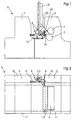
- Fig. 1 shows a first embodiment of the invention in side view. Two printing units 2 of a printing press 9 are shown. An additional device 1 is shown both in its working position 3 and in its vertical waiting position 5. Of course, it occupies one or the other position. Such an additional device 1 can be assigned to a specific or to any printing unit 2 of a printing press 9. In the working position 3, the additional device 1 can carry out work on a cylinder, for example on the plate cylinder 6 or on the rubber cylinder 7. In the example shown, it is an additional device 1, for example a laser unit, which images a printing plate 25 located on the plate cylinder 6.
- the printing plate 25 shown shows which space must be released for this printing plate change
- the maintenance position 5 shown is the vertical position that the additional device 1 must assume in order to carry out larger work on the printing unit 2.
- the horizontal displacement 23 serves a linear guide 12, and the pivoting into the vertical position 5 serves a pivot mechanism 8.
- Fig. 2 shows the same embodiment in plan view, it can be seen how the additional device 1 is in its working position 3 on the printing unit 2, usually engages in this, for example, to make images of a printing plate 25 located on the plate cylinder 6.
- This top view shows how the side wall 11 of the printing unit 2 is completely free on the operating side and how the additional device 1 is in its vertical position 5 next to the other side wall 10, that is to say on the drive side of the printing press 9.
- the additional device 1 is not in the way because the operator steps between the printing units 2 from the operating side in order to carry out necessary maintenance work.
- FIG. 3 shows a view of this exemplary embodiment between the printing units 2, in which the printing press 9 is shown in section at this point.
- the additional device 1 is shown both in its working position 3 and in its vertical maintenance position 5.
- the pivoting from the horizontal position 4 to the maintenance position 5 is carried out by a pivoting mechanism 8.
- the pivoting can take place automatically or by hand.
- a spring for example a gas pressure spring 22, is expediently arranged to support the pivoting movement.
- another drive can also be located at this point, which carries out the adjustment automatically.
- Fig. 4 shows a second embodiment in perspective view with an additional device 1 in its working position 3.
- a linear guide 12 which is designed such that the additional device 1 can be pivoted about the linear guide 12. It can be a covered round rod.
- the curve 20 is formed with such an entanglement that the path of the cam roller 21 changes its orientation by 90 °.
- a drive 19 is arranged, which takes over the adjusting movement.
- This drive can be pneumatic, hydraulic or electrical.
- Fig. 6 shows the pivoting of the additional device 1 in its vertical position 5. This is achieved in that the cam roller 21 passes through the setting of the curve 20 between the maintenance position 4 and the maintenance position 5, and thereby the pivoting movement is brought about.
- a spring for example a gas pressure spring 22, is also expediently provided in this exemplary embodiment, but this has not been shown here for the sake of simplicity.
- FIG. 7 shows a printing press 9 with an additional device 1 according to the invention and a printing plate changing device 24, 24 ', each in different working positions.
- the additional device 1 is in its working position 3, in which it uses a laser to image the printing plate 25 on the plate cylinder 6, for example.
- the additional device 1 was shifted into its horizontal maintenance position 4, for example in order to initiate a printing plate change.
- the right printing unit 2 shows how the automatic printing plate changer 24 'is in its printing plate changing position, in which it removes a printing plate 25 from the plate cylinder 6 or feeds a printing plate 25 to the plate cylinder 6.
- This illustration shows how a horizontal shift of the Additional device 1 is sufficient to change the printing plate, for example by means of an automatic printing plate changer 24 or a semi-automatic Pressure plate changer.
- this shift into the horizontal maintenance position 4 is sufficient. Only for larger service work, such as when changing blankets or a printing unit cleaning, the additional device 1 must be in the vertical maintenance position 5 can be moved.
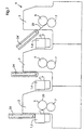
- Fig. 8 shows a centering 13 and locking device 14 in plan view.
- Pneumatic elements 17 are arranged on both sides of the additional device 1 on the side walls 10 and 11, each of which acts on the tensioning lever 26 and thereby serves as a locking device 14.
- the tensioning levers 26 can be articulated on the side walls 10 and 11 and serve to increase the force by dimensioning the levers.
- FIG. 9 shows the function of this locking device 14, by means of which bolts 15 arranged on the machine are pressed against contact surfaces 18 of a centering device 13.
- the upper bolt 15 is pressed into the contact surfaces 18 of a prism 27, whereby an exact positioning of the additional device 1 is achieved.
- a stop 16 with a bolt 15 and a straight contact surface 18 in the lower area serves to ensure that the vertical orientation of the additional device 1 is also given. In this way it is achieved that the additional device 1 is positioned exactly and an imaging device for the respective imaging is positioned exactly in the machine register.
- the horizontal working positions for example of the laser steel, must be reached for the same by means of a horizontal actuating device. This is adjusted to the side wall by at least one sensor.
- centering device 13 and locking device shown above 14 is only one embodiment, numerous other interlocks are conceivable, it being essential that the additional device 1 in height and the vertical orientation is positioned exactly to match an edit with the machine register.
Landscapes
- Engineering & Computer Science (AREA)
- Mechanical Engineering (AREA)
- Rotary Presses (AREA)
- Inking, Control Or Cleaning Of Printing Machines (AREA)
- Manufacture Or Reproduction Of Printing Formes (AREA)
Applications Claiming Priority (2)
| Application Number | Priority Date | Filing Date | Title |
|---|---|---|---|
| DE19814661 | 1998-03-31 | ||
| DE19814661A DE19814661B4 (de) | 1998-03-31 | 1998-03-31 | Zusatzeinrichtung für ein Druckwerk |
Publications (2)
| Publication Number | Publication Date |
|---|---|
| EP0949071A1 EP0949071A1 (de) | 1999-10-13 |
| EP0949071B1 true EP0949071B1 (de) | 2002-12-18 |
Family
ID=7863286
Family Applications (1)
| Application Number | Title | Priority Date | Filing Date |
|---|---|---|---|
| EP99105615A Expired - Lifetime EP0949071B1 (de) | 1998-03-31 | 1999-03-19 | Zusatzeinrichtung für ein Druckwerk |
Country Status (5)
| Country | Link |
|---|---|
| US (1) | US6510795B1 (enExample) |
| EP (1) | EP0949071B1 (enExample) |
| JP (1) | JP4321902B2 (enExample) |
| DE (2) | DE19814661B4 (enExample) |
| IL (1) | IL129205A (enExample) |
Families Citing this family (23)
| Publication number | Priority date | Publication date | Assignee | Title |
|---|---|---|---|---|
| DE19961869B4 (de) * | 1999-12-22 | 2005-01-13 | Man Roland Druckmaschinen Ag | Justiervorrichtung, insbesondere für Traversen mit Bebilderungseinrichtungen für Druckformen von Druckmaschinen |
| DE10004573A1 (de) * | 2000-02-02 | 2001-08-09 | Koenig & Bauer Ag | Verfahren zur Herstellung eines Mehrfarbendruckes |
| DE20006513U1 (de) | 2000-04-08 | 2000-07-13 | MAN Roland Druckmaschinen AG, 63075 Offenbach | Bogen-Rotationsdruckmaschine |
| JP2001322234A (ja) | 2000-05-17 | 2001-11-20 | Komori Corp | 印刷機 |
| JP2001322235A (ja) | 2000-05-17 | 2001-11-20 | Komori Corp | 印刷機 |
| JP2001322233A (ja) * | 2000-05-17 | 2001-11-20 | Komori Corp | 印刷機 |
| JP2001322238A (ja) | 2000-05-17 | 2001-11-20 | Komori Corp | 印刷機 |
| EP1155823A3 (en) * | 2000-05-17 | 2006-01-18 | Komori Corporation | Printing press |
| DE10155038B4 (de) * | 2000-12-04 | 2014-03-06 | Heidelberger Druckmaschinen Ag | Wechselbare Bebilderungseinrichtung zum Bebildern von Druckformen |
| US6997108B2 (en) | 2001-08-21 | 2006-02-14 | Mitsubishi Heavy Industries, Ltd. | Plate-making type printing press, multi-color printing press and plate-making type printing method |
| US7004717B2 (en) * | 2002-04-05 | 2006-02-28 | Agfa Corporation | Plate cassette loader for platesetter |
| JP2004209963A (ja) | 2002-11-11 | 2004-07-29 | Dainippon Screen Mfg Co Ltd | 印刷機 |
| DE10302213B3 (de) * | 2003-01-22 | 2004-03-04 | Koenig & Bauer Ag | Druckmaschine mit mindestens einem Formzylinder |
| EP1464485A3 (en) * | 2003-04-05 | 2007-02-21 | Agfa Corporation | Plate cassette loader for platesetter. |
| US6952993B2 (en) * | 2003-12-02 | 2005-10-11 | Shinohara Machinery Co., Ltd. | Versatile satellite-type printing press |
| USH2159H1 (en) | 2004-01-16 | 2006-07-04 | The United States Of America As Represented By The Secretary Of The Navy | Guidance of treatment devices on target surfaces |
| GB2413530A (en) * | 2004-04-29 | 2005-11-02 | Goss Graphic Systems Ltd | Printing plate module and printing press |
| US8051774B2 (en) * | 2004-04-29 | 2011-11-08 | Goss Graphic Systems Limited | Printing plate module, printing press, and method of mounting plates |
| DE102004043503A1 (de) * | 2004-09-09 | 2006-03-30 | Man Roland Druckmaschinen Ag | Druckeinheit einer Druckmaschine |
| JP2006103179A (ja) * | 2004-10-06 | 2006-04-20 | Dainippon Screen Mfg Co Ltd | 印刷機および印刷版記録装置 |
| GB2425987A (en) * | 2005-05-09 | 2006-11-15 | Goss Graphic Systems Ltd | Printing plate unloading apparatus and method |
| GB2428634B (en) * | 2005-08-04 | 2008-09-17 | Goss Graphic Systems Ltd | Printing press |
| DE102009020753A1 (de) * | 2009-04-28 | 2010-11-04 | Spm Steuer Gmbh & Co. Kg | Druckveredelungsmaschine |
Family Cites Families (24)
| Publication number | Priority date | Publication date | Assignee | Title |
|---|---|---|---|---|
| FR2117385A5 (enExample) * | 1970-12-10 | 1972-07-21 | Moestue Hans | |
| JPS51141014A (en) * | 1975-05-28 | 1976-12-04 | Canon Kk | Ink roller cartridge |
| DE3143089A1 (de) * | 1981-10-30 | 1983-05-26 | Heidelberger Druckmaschinen Ag, 6900 Heidelberg | Vorrichtung zum trocknen von bedruckten bogen an offsetdruckmaschinen |
| IT8323664V0 (it) | 1983-11-25 | 1983-11-25 | Gino Ventura | Dispositivo per la stampa di una numerazione applicabile a macchine offset del tipo a cilindri orizzontali. |
| DE3407681A1 (de) | 1984-03-02 | 1985-09-05 | Heidelberger Druckmaschinen Ag, 6900 Heidelberg | Vorrichtung zum austauschen einer, mit einer numerierwelle zur aufnahme von ziffernwerken versehenen numerier- und eindruckvorrichtung in druckmaschinen |
| US4723487A (en) * | 1985-04-25 | 1988-02-09 | Richardson Orland W | Screen printing method and apparatus |
| DE3525743A1 (de) * | 1985-07-19 | 1987-01-29 | Werner Kroscky | Lackierwerk fuer eine mit eindruckwerk ausgeruestete offsetdruckmaschine |
| US4727807A (en) * | 1985-09-30 | 1988-03-01 | Tokyo Kikai Seisakusho | Apparatus for automatically mounting and removing printing plates in rotary printing press |
| US4796556A (en) * | 1987-06-24 | 1989-01-10 | Birow, Inc. | Adjustable coating and printing apparatus |
| JPH0798389B2 (ja) * | 1988-07-22 | 1995-10-25 | リョービ株式会社 | 2つの印刷ユニットを持つオフセット印刷機 |
| DE3837898A1 (de) * | 1988-11-09 | 1990-06-13 | Roland Man Druckmasch | Verfahren und vorrichtung zur integrierten druckformherstellung an einer offset- druckmaschine |
| US5072671A (en) | 1988-11-09 | 1991-12-17 | Man Roland Druckmaschinen Ag | System and method to apply a printing image on a printing machine cylinder in accordance with electronically furnished image information |
| DE4118697A1 (de) * | 1991-06-07 | 1992-12-10 | Roland Man Druckmasch | Einrichtung zum farbwechsel bei farbwerken |
| DE4130359C2 (de) * | 1991-09-12 | 1997-04-17 | Heidelberger Druckmasch Ag | Vorrichtung zum Ab- und/oder Zuführen von Druckplatten einer Druckmaschine |
| US5224424A (en) * | 1991-12-31 | 1993-07-06 | Layland Jon L | Printing press wash-up system |
| DE4218422C2 (de) * | 1992-06-04 | 1994-04-28 | Heidelberger Druckmasch Ag | Bogen-Offsetrotationsdruckmaschine mit herausnehmbarem Eindruck- oder Veredelungswerk |
| US5794531A (en) * | 1992-06-23 | 1998-08-18 | Keller; James J. | Multiple color offset rotary printing press with horizontal slide access |
| DE9405223U1 (de) * | 1994-03-28 | 1994-06-09 | Man Roland Druckmaschinen Ag, 63069 Offenbach | Trocknervorrichtung für eine Bogenrotationsdruckmaschine |
| DE4443516C1 (de) | 1994-12-07 | 1996-04-11 | Heidelberger Druckmasch Ag | Numerierwerk |
| US6435086B1 (en) * | 1995-05-04 | 2002-08-20 | Howard W. DeMoore | Retractable inking/coating apparatus having ferris movement between printing units |
| US5630363A (en) * | 1995-08-14 | 1997-05-20 | Williamson Printing Corporation | Combined lithographic/flexographic printing apparatus and process |
| DE29617261U1 (de) * | 1996-10-04 | 1996-11-21 | Heidelberger Druckmaschinen Ag, 69115 Heidelberg | Bogenrotationsdruckmaschine |
| JPH1120292A (ja) * | 1997-07-01 | 1999-01-26 | Riso Kagaku Corp | 孔版印刷機の版胴支持構造 |
| DE19820159A1 (de) * | 1997-08-07 | 1999-02-11 | Heidelberger Druckmasch Ag | Stellvorrichtung für eine Druckmaschine |
-
1998
- 1998-03-31 DE DE19814661A patent/DE19814661B4/de not_active Expired - Fee Related
-
1999
- 1999-03-19 DE DE59903801T patent/DE59903801D1/de not_active Expired - Lifetime
- 1999-03-19 EP EP99105615A patent/EP0949071B1/de not_active Expired - Lifetime
- 1999-03-28 IL IL12920599A patent/IL129205A/en not_active IP Right Cessation
- 1999-03-31 US US09/283,821 patent/US6510795B1/en not_active Expired - Fee Related
- 1999-03-31 JP JP09129299A patent/JP4321902B2/ja not_active Expired - Fee Related
Also Published As
| Publication number | Publication date |
|---|---|
| DE19814661B4 (de) | 2004-05-13 |
| JPH11314353A (ja) | 1999-11-16 |
| US6510795B1 (en) | 2003-01-28 |
| IL129205A0 (en) | 2000-02-17 |
| DE59903801D1 (de) | 2003-01-30 |
| DE19814661A1 (de) | 1999-10-07 |
| EP0949071A1 (de) | 1999-10-13 |
| JP4321902B2 (ja) | 2009-08-26 |
| IL129205A (en) | 2001-10-31 |
Similar Documents
| Publication | Publication Date | Title |
|---|---|---|
| EP0949071B1 (de) | Zusatzeinrichtung für ein Druckwerk | |
| EP0530577B1 (de) | Vorrichtung zur Positionierung eines dem automatischen Druckplattenwechsel dienenden Magazins | |
| DE10008215A1 (de) | Druckwerk für eine Rotationsmaschine mit Kreuzschlitten | |
| EP0153620B1 (de) | Vorrichtung zum Austauschen einer, mit einer Numerierwelle zur Aufname von ziffernwerken versehenen Numerier- und Ein- druckvorrichtung in Druckmaschinen | |
| EP0431364B1 (de) | Handhabungsvorrichtung | |
| DE10221330A1 (de) | Druckwerk | |
| DE69025798T2 (de) | Mehrfarbige Flexodruckmaschine mit einer Vorrichtung zum automatischen Auf- und Abladen von Plattenzylindern | |
| DE4224832C3 (de) | Vorrichtung zur Positionierung eines dem automatischen Druckplattenwechsel dienenden Magazins | |
| EP0384385A2 (de) | Vorrichtung zur Veränderung der Bahnlage einer Bedruckstoffbahn | |
| EP1075943B1 (de) | Druckwerk | |
| DE4322027A1 (de) | Vorrichtung zum automatischen Wechseln einer Druckplatte | |
| DE3230833C2 (de) | Vorrichtung mit mehreren Arbeitsstationen zum Bedrucken, Ausstanzen bzw. Zuschneiden von Kartonzuschnitten | |
| DE10223666B4 (de) | Farbwerksaufbau bei Flexodruckmaschinen | |
| EP1075944B1 (de) | Druckwerk | |
| EP0704302B1 (de) | Vorrichtung zum Zuführen einer Druckplatte zum Plattenzylinder einer Druckmaschine | |
| EP1592556B1 (de) | Druckwerk einer druckmaschine | |
| CH695766A5 (de) | Rotationsdruckmaschine mit Bebilderungsvorrichtung. | |
| DE3246938C2 (de) | An- und Abstellvorrichtung für den Plattenzylinder und die Farbauftragswalze einer Flexodruckmaschine | |
| EP1140498B1 (de) | Rollenrotationsdruckmaschine | |
| CH685380A5 (de) | Rotationsdruckmaschine. | |
| EP1769912B1 (de) | Rollenrotationsdruckmaschine | |
| DE4100901A1 (de) | Verfahren zum vorstapeln in einem bogenanleger von rotationsdruckmaschinen | |
| DE19753820A1 (de) | Vorrichtung zum gegenseitigen Anstellen von Druckwerkzylindern | |
| DE19947281A1 (de) | Zusatzeinrichtung für ein Druckwerk | |
| DE9104151U1 (de) | Vorrichtung zum Einstellen des Achsabstandes zwischen Gummizylinder und Druckzylinder einer Bogenoffsetdruckmaschine |
Legal Events
| Date | Code | Title | Description |
|---|---|---|---|
| PUAI | Public reference made under article 153(3) epc to a published international application that has entered the european phase |
Free format text: ORIGINAL CODE: 0009012 |
|
| AK | Designated contracting states |
Kind code of ref document: A1 Designated state(s): BE CH DE FR GB IT LI NL |
|
| AX | Request for extension of the european patent |
Free format text: AL;LT;LV;MK;RO;SI |
|
| 17P | Request for examination filed |
Effective date: 19991029 |
|
| AKX | Designation fees paid |
Free format text: BE CH DE FR GB IT LI NL |
|
| 17Q | First examination report despatched |
Effective date: 20010810 |
|
| GRAG | Despatch of communication of intention to grant |
Free format text: ORIGINAL CODE: EPIDOS AGRA |
|
| GRAG | Despatch of communication of intention to grant |
Free format text: ORIGINAL CODE: EPIDOS AGRA |
|
| GRAH | Despatch of communication of intention to grant a patent |
Free format text: ORIGINAL CODE: EPIDOS IGRA |
|
| GRAH | Despatch of communication of intention to grant a patent |
Free format text: ORIGINAL CODE: EPIDOS IGRA |
|
| GRAA | (expected) grant |
Free format text: ORIGINAL CODE: 0009210 |
|
| AK | Designated contracting states |
Kind code of ref document: B1 Designated state(s): BE CH DE FR GB IT LI NL |
|
| PG25 | Lapsed in a contracting state [announced via postgrant information from national office to epo] |
Ref country code: NL Free format text: LAPSE BECAUSE OF FAILURE TO SUBMIT A TRANSLATION OF THE DESCRIPTION OR TO PAY THE FEE WITHIN THE PRESCRIBED TIME-LIMIT Effective date: 20021218 Ref country code: IT Free format text: LAPSE BECAUSE OF FAILURE TO SUBMIT A TRANSLATION OF THE DESCRIPTION OR TO PAY THE FEE WITHIN THE PRESCRIBED TIME-LIMIT;WARNING: LAPSES OF ITALIAN PATENTS WITH EFFECTIVE DATE BEFORE 2007 MAY HAVE OCCURRED AT ANY TIME BEFORE 2007. THE CORRECT EFFECTIVE DATE MAY BE DIFFERENT FROM THE ONE RECORDED. Effective date: 20021218 Ref country code: GB Free format text: LAPSE BECAUSE OF FAILURE TO SUBMIT A TRANSLATION OF THE DESCRIPTION OR TO PAY THE FEE WITHIN THE PRESCRIBED TIME-LIMIT Effective date: 20021218 Ref country code: FR Free format text: LAPSE BECAUSE OF FAILURE TO SUBMIT A TRANSLATION OF THE DESCRIPTION OR TO PAY THE FEE WITHIN THE PRESCRIBED TIME-LIMIT Effective date: 20021218 |
|
| REG | Reference to a national code |
Ref country code: GB Ref legal event code: FG4D Free format text: NOT ENGLISH |
|
| REG | Reference to a national code |
Ref country code: CH Ref legal event code: EP |
|
| REF | Corresponds to: |
Ref document number: 59903801 Country of ref document: DE Date of ref document: 20030130 Kind code of ref document: P Ref document number: 59903801 Country of ref document: DE Date of ref document: 20030130 |
|
| PG25 | Lapsed in a contracting state [announced via postgrant information from national office to epo] |
Ref country code: LI Free format text: LAPSE BECAUSE OF NON-PAYMENT OF DUE FEES Effective date: 20030331 Ref country code: CH Free format text: LAPSE BECAUSE OF NON-PAYMENT OF DUE FEES Effective date: 20030331 Ref country code: BE Free format text: LAPSE BECAUSE OF NON-PAYMENT OF DUE FEES Effective date: 20030331 |
|
| GBV | Gb: ep patent (uk) treated as always having been void in accordance with gb section 77(7)/1977 [no translation filed] |
Effective date: 20021218 |
|
| BERE | Be: lapsed |
Owner name: *HEIDELBERGER DRUCKMASCHINEN A.G. Effective date: 20030331 |
|
| PLBE | No opposition filed within time limit |
Free format text: ORIGINAL CODE: 0009261 |
|
| STAA | Information on the status of an ep patent application or granted ep patent |
Free format text: STATUS: NO OPPOSITION FILED WITHIN TIME LIMIT |
|
| EN | Fr: translation not filed | ||
| REG | Reference to a national code |
Ref country code: CH Ref legal event code: PL |
|
| 26N | No opposition filed |
Effective date: 20030919 |
|
| PGFP | Annual fee paid to national office [announced via postgrant information from national office to epo] |
Ref country code: DE Payment date: 20130424 Year of fee payment: 15 |
|
| REG | Reference to a national code |
Ref country code: DE Ref legal event code: R119 Ref document number: 59903801 Country of ref document: DE |
|
| REG | Reference to a national code |
Ref country code: DE Ref legal event code: R119 Ref document number: 59903801 Country of ref document: DE Effective date: 20141001 |
|
| PG25 | Lapsed in a contracting state [announced via postgrant information from national office to epo] |
Ref country code: DE Free format text: LAPSE BECAUSE OF NON-PAYMENT OF DUE FEES Effective date: 20141001 |