EP0942839B1 - System und verfahren zur detektion von fahrzeugüberrollzuständen - Google Patents
System und verfahren zur detektion von fahrzeugüberrollzuständen Download PDFInfo
- Publication number
- EP0942839B1 EP0942839B1 EP97949791A EP97949791A EP0942839B1 EP 0942839 B1 EP0942839 B1 EP 0942839B1 EP 97949791 A EP97949791 A EP 97949791A EP 97949791 A EP97949791 A EP 97949791A EP 0942839 B1 EP0942839 B1 EP 0942839B1
- Authority
- EP
- European Patent Office
- Prior art keywords
- vehicle
- load transfer
- roll moment
- gravity
- axle
- Prior art date
- Legal status (The legal status is an assumption and is not a legal conclusion. Google has not performed a legal analysis and makes no representation as to the accuracy of the status listed.)
- Expired - Lifetime
Links
- 238000000034 method Methods 0.000 title claims description 28
- 238000001514 detection method Methods 0.000 title claims description 7
- 230000005484 gravity Effects 0.000 claims abstract description 84
- 238000012546 transfer Methods 0.000 claims abstract description 84
- 230000001133 acceleration Effects 0.000 claims abstract description 65
- 239000000725 suspension Substances 0.000 claims abstract description 40
- 230000000007 visual effect Effects 0.000 claims description 7
- 238000013500 data storage Methods 0.000 claims description 6
- 230000003287 optical effect Effects 0.000 claims description 6
- 230000003068 static effect Effects 0.000 claims description 5
- 230000000712 assembly Effects 0.000 claims description 4
- 238000000429 assembly Methods 0.000 claims description 4
- 238000012545 processing Methods 0.000 claims description 3
- 238000005259 measurement Methods 0.000 abstract description 13
- 230000008859 change Effects 0.000 description 6
- 238000010586 diagram Methods 0.000 description 5
- 238000013459 approach Methods 0.000 description 4
- 239000000835 fiber Substances 0.000 description 4
- 230000006870 function Effects 0.000 description 4
- 239000013598 vector Substances 0.000 description 4
- 238000004458 analytical method Methods 0.000 description 3
- 230000000694 effects Effects 0.000 description 3
- 230000004044 response Effects 0.000 description 3
- 238000013016 damping Methods 0.000 description 2
- 238000005516 engineering process Methods 0.000 description 2
- 239000007788 liquid Substances 0.000 description 2
- 238000011160 research Methods 0.000 description 2
- 230000035945 sensitivity Effects 0.000 description 2
- 230000004913 activation Effects 0.000 description 1
- 230000002411 adverse Effects 0.000 description 1
- 230000008901 benefit Effects 0.000 description 1
- 238000004364 calculation method Methods 0.000 description 1
- 239000000356 contaminant Substances 0.000 description 1
- 230000008878 coupling Effects 0.000 description 1
- 238000010168 coupling process Methods 0.000 description 1
- 238000005859 coupling reaction Methods 0.000 description 1
- 230000001419 dependent effect Effects 0.000 description 1
- 238000006073 displacement reaction Methods 0.000 description 1
- 230000007613 environmental effect Effects 0.000 description 1
- 239000000383 hazardous chemical Substances 0.000 description 1
- 238000009434 installation Methods 0.000 description 1
- 230000002452 interceptive effect Effects 0.000 description 1
- 238000012886 linear function Methods 0.000 description 1
- 230000036961 partial effect Effects 0.000 description 1
- 230000008569 process Effects 0.000 description 1
- 230000000135 prohibitive effect Effects 0.000 description 1
- 230000002829 reductive effect Effects 0.000 description 1
- 230000001105 regulatory effect Effects 0.000 description 1
- 238000005096 rolling process Methods 0.000 description 1
- XLYOFNOQVPJJNP-UHFFFAOYSA-N water Substances O XLYOFNOQVPJJNP-UHFFFAOYSA-N 0.000 description 1
- 230000003442 weekly effect Effects 0.000 description 1
Images


Classifications
-
- B—PERFORMING OPERATIONS; TRANSPORTING
- B60—VEHICLES IN GENERAL
- B60G—VEHICLE SUSPENSION ARRANGEMENTS
- B60G17/00—Resilient suspensions having means for adjusting the spring or vibration-damper characteristics, for regulating the distance between a supporting surface and a sprung part of vehicle or for locking suspension during use to meet varying vehicular or surface conditions, e.g. due to speed or load
- B60G17/015—Resilient suspensions having means for adjusting the spring or vibration-damper characteristics, for regulating the distance between a supporting surface and a sprung part of vehicle or for locking suspension during use to meet varying vehicular or surface conditions, e.g. due to speed or load the regulating means comprising electric or electronic elements
- B60G17/016—Resilient suspensions having means for adjusting the spring or vibration-damper characteristics, for regulating the distance between a supporting surface and a sprung part of vehicle or for locking suspension during use to meet varying vehicular or surface conditions, e.g. due to speed or load the regulating means comprising electric or electronic elements characterised by their responsiveness, when the vehicle is travelling, to specific motion, a specific condition, or driver input
- B60G17/0162—Resilient suspensions having means for adjusting the spring or vibration-damper characteristics, for regulating the distance between a supporting surface and a sprung part of vehicle or for locking suspension during use to meet varying vehicular or surface conditions, e.g. due to speed or load the regulating means comprising electric or electronic elements characterised by their responsiveness, when the vehicle is travelling, to specific motion, a specific condition, or driver input mainly during a motion involving steering operation, e.g. cornering, overtaking
-
- B—PERFORMING OPERATIONS; TRANSPORTING
- B60—VEHICLES IN GENERAL
- B60G—VEHICLE SUSPENSION ARRANGEMENTS
- B60G17/00—Resilient suspensions having means for adjusting the spring or vibration-damper characteristics, for regulating the distance between a supporting surface and a sprung part of vehicle or for locking suspension during use to meet varying vehicular or surface conditions, e.g. due to speed or load
- B60G17/015—Resilient suspensions having means for adjusting the spring or vibration-damper characteristics, for regulating the distance between a supporting surface and a sprung part of vehicle or for locking suspension during use to meet varying vehicular or surface conditions, e.g. due to speed or load the regulating means comprising electric or electronic elements
- B60G17/018—Resilient suspensions having means for adjusting the spring or vibration-damper characteristics, for regulating the distance between a supporting surface and a sprung part of vehicle or for locking suspension during use to meet varying vehicular or surface conditions, e.g. due to speed or load the regulating means comprising electric or electronic elements characterised by the use of a specific signal treatment or control method
- B60G17/0185—Resilient suspensions having means for adjusting the spring or vibration-damper characteristics, for regulating the distance between a supporting surface and a sprung part of vehicle or for locking suspension during use to meet varying vehicular or surface conditions, e.g. due to speed or load the regulating means comprising electric or electronic elements characterised by the use of a specific signal treatment or control method for failure detection
-
- B—PERFORMING OPERATIONS; TRANSPORTING
- B61—RAILWAYS
- B61F—RAIL VEHICLE SUSPENSIONS, e.g. UNDERFRAMES, BOGIES OR ARRANGEMENTS OF WHEEL AXLES; RAIL VEHICLES FOR USE ON TRACKS OF DIFFERENT WIDTH; PREVENTING DERAILING OF RAIL VEHICLES; WHEEL GUARDS, OBSTRUCTION REMOVERS OR THE LIKE FOR RAIL VEHICLES
- B61F5/00—Constructional details of bogies; Connections between bogies and vehicle underframes; Arrangements or devices for adjusting or allowing self-adjustment of wheel axles or bogies when rounding curves
- B61F5/02—Arrangements permitting limited transverse relative movements between vehicle underframe or bolster and bogie; Connections between underframes and bogies
- B61F5/22—Guiding of the vehicle underframes with respect to the bogies
- B61F5/24—Means for damping or minimising the canting, skewing, pitching, or plunging movements of the underframes
- B61F5/245—Means for damping or minimising the canting, skewing, pitching, or plunging movements of the underframes by active damping, i.e. with means to vary the damping characteristics in accordance with track or vehicle induced reactions, especially in high speed mode
-
- G—PHYSICS
- G01—MEASURING; TESTING
- G01M—TESTING STATIC OR DYNAMIC BALANCE OF MACHINES OR STRUCTURES; TESTING OF STRUCTURES OR APPARATUS, NOT OTHERWISE PROVIDED FOR
- G01M1/00—Testing static or dynamic balance of machines or structures
- G01M1/12—Static balancing; Determining position of centre of gravity
- G01M1/122—Determining position of centre of gravity
-
- B—PERFORMING OPERATIONS; TRANSPORTING
- B60—VEHICLES IN GENERAL
- B60G—VEHICLE SUSPENSION ARRANGEMENTS
- B60G2300/00—Indexing codes relating to the type of vehicle
- B60G2300/02—Trucks; Load vehicles
- B60G2300/024—Light trucks
-
- B—PERFORMING OPERATIONS; TRANSPORTING
- B60—VEHICLES IN GENERAL
- B60G—VEHICLE SUSPENSION ARRANGEMENTS
- B60G2300/00—Indexing codes relating to the type of vehicle
- B60G2300/02—Trucks; Load vehicles
- B60G2300/026—Heavy duty trucks
-
- B—PERFORMING OPERATIONS; TRANSPORTING
- B60—VEHICLES IN GENERAL
- B60G—VEHICLE SUSPENSION ARRANGEMENTS
- B60G2400/00—Indexing codes relating to detected, measured or calculated conditions or factors
- B60G2400/10—Acceleration; Deceleration
- B60G2400/104—Acceleration; Deceleration lateral or transversal with regard to vehicle
-
- B—PERFORMING OPERATIONS; TRANSPORTING
- B60—VEHICLES IN GENERAL
- B60G—VEHICLE SUSPENSION ARRANGEMENTS
- B60G2400/00—Indexing codes relating to detected, measured or calculated conditions or factors
- B60G2400/20—Speed
- B60G2400/206—Body oscillation speed; Body vibration frequency
-
- B—PERFORMING OPERATIONS; TRANSPORTING
- B60—VEHICLES IN GENERAL
- B60G—VEHICLE SUSPENSION ARRANGEMENTS
- B60G2400/00—Indexing codes relating to detected, measured or calculated conditions or factors
- B60G2400/60—Load
-
- B—PERFORMING OPERATIONS; TRANSPORTING
- B60—VEHICLES IN GENERAL
- B60G—VEHICLE SUSPENSION ARRANGEMENTS
- B60G2400/00—Indexing codes relating to detected, measured or calculated conditions or factors
- B60G2400/60—Load
- B60G2400/61—Load distribution
-
- B—PERFORMING OPERATIONS; TRANSPORTING
- B60—VEHICLES IN GENERAL
- B60G—VEHICLE SUSPENSION ARRANGEMENTS
- B60G2400/00—Indexing codes relating to detected, measured or calculated conditions or factors
- B60G2400/60—Load
- B60G2400/63—Location of the center of gravity
-
- B—PERFORMING OPERATIONS; TRANSPORTING
- B60—VEHICLES IN GENERAL
- B60G—VEHICLE SUSPENSION ARRANGEMENTS
- B60G2400/00—Indexing codes relating to detected, measured or calculated conditions or factors
- B60G2400/80—Exterior conditions
- B60G2400/82—Ground surface
- B60G2400/824—Travel path sensing; Track monitoring
-
- B—PERFORMING OPERATIONS; TRANSPORTING
- B60—VEHICLES IN GENERAL
- B60G—VEHICLE SUSPENSION ARRANGEMENTS
- B60G2400/00—Indexing codes relating to detected, measured or calculated conditions or factors
- B60G2400/90—Other conditions or factors
- B60G2400/91—Frequency
-
- B—PERFORMING OPERATIONS; TRANSPORTING
- B60—VEHICLES IN GENERAL
- B60G—VEHICLE SUSPENSION ARRANGEMENTS
- B60G2600/00—Indexing codes relating to particular elements, systems or processes used on suspension systems or suspension control systems
- B60G2600/02—Retarders, delaying means, dead zones, threshold values, cut-off frequency, timer interruption
-
- B—PERFORMING OPERATIONS; TRANSPORTING
- B60—VEHICLES IN GENERAL
- B60G—VEHICLE SUSPENSION ARRANGEMENTS
- B60G2600/00—Indexing codes relating to particular elements, systems or processes used on suspension systems or suspension control systems
- B60G2600/04—Means for informing, instructing or displaying
- B60G2600/042—Monitoring means
-
- B—PERFORMING OPERATIONS; TRANSPORTING
- B60—VEHICLES IN GENERAL
- B60G—VEHICLE SUSPENSION ARRANGEMENTS
- B60G2600/00—Indexing codes relating to particular elements, systems or processes used on suspension systems or suspension control systems
- B60G2600/04—Means for informing, instructing or displaying
- B60G2600/044—Alarm means
-
- B—PERFORMING OPERATIONS; TRANSPORTING
- B60—VEHICLES IN GENERAL
- B60G—VEHICLE SUSPENSION ARRANGEMENTS
- B60G2800/00—Indexing codes relating to the type of movement or to the condition of the vehicle and to the end result to be achieved by the control action
- B60G2800/01—Attitude or posture control
- B60G2800/012—Rolling condition
-
- B—PERFORMING OPERATIONS; TRANSPORTING
- B60—VEHICLES IN GENERAL
- B60G—VEHICLE SUSPENSION ARRANGEMENTS
- B60G2800/00—Indexing codes relating to the type of movement or to the condition of the vehicle and to the end result to be achieved by the control action
- B60G2800/24—Steering, cornering
-
- B—PERFORMING OPERATIONS; TRANSPORTING
- B60—VEHICLES IN GENERAL
- B60G—VEHICLE SUSPENSION ARRANGEMENTS
- B60G2800/00—Indexing codes relating to the type of movement or to the condition of the vehicle and to the end result to be achieved by the control action
- B60G2800/70—Estimating or calculating vehicle parameters or state variables
- B60G2800/704—Estimating or calculating vehicle parameters or state variables predicting unorthodox driving conditions for safe or optimal driving
-
- B—PERFORMING OPERATIONS; TRANSPORTING
- B60—VEHICLES IN GENERAL
- B60G—VEHICLE SUSPENSION ARRANGEMENTS
- B60G2800/00—Indexing codes relating to the type of movement or to the condition of the vehicle and to the end result to be achieved by the control action
- B60G2800/90—System Controller type
- B60G2800/91—Suspension Control
- B60G2800/912—Attitude Control; levelling control
- B60G2800/9124—Roll-over protection systems, e.g. for warning or control
-
- B—PERFORMING OPERATIONS; TRANSPORTING
- B60—VEHICLES IN GENERAL
- B60T—VEHICLE BRAKE CONTROL SYSTEMS OR PARTS THEREOF; BRAKE CONTROL SYSTEMS OR PARTS THEREOF, IN GENERAL; ARRANGEMENT OF BRAKING ELEMENTS ON VEHICLES IN GENERAL; PORTABLE DEVICES FOR PREVENTING UNWANTED MOVEMENT OF VEHICLES; VEHICLE MODIFICATIONS TO FACILITATE COOLING OF BRAKES
- B60T2230/00—Monitoring, detecting special vehicle behaviour; Counteracting thereof
- B60T2230/03—Overturn, rollover
Definitions
- the present invention relates generally to vehicle safety and, more particularly, to a system and method for the detection of conditions leading to vehicle rollover according to the preamble of claims 1, 29 and 39.
- Another approach to reducing the frequency of rollover accidents is to provide data to drivers to indicate when a rollover accident is likely to occur.
- a tractor-trailer combination covers its own length in less than a second. For this reason, detection systems alone cannot effectively predict when a rollover accident is about to occur.
- data can be provided to the driver to permit the driver to assess the likelihood of rollover conditions.
- EP-A-684 150 describes a system for determining the stability of a vehicle.
- Pressure sensors are used to measure the pressure or change in pressure on the left-hand and right-hand wheels of the vehicle. Furthermore, a sensor is used to measure the transverse acceleration. Based on these measurements, the resultant force acting on the vehicle is determined using a processor and a simple algorithm. The result is compared to values in a table to determine when the vehicle has reached a critical situation. This critical situation could be indicated to the driver of the vehicle by an audible alarm. Alternatively, a visual display could be used indicating the current condition of the vehicle. Such a display could change its color from green for normal conditions through orange to red for very critical situations.
- US-A-4 480 714 describes a system for preventing a carrier from turning sideways.
- the system derives the dynamic instability of the vehicle during turning based on measured steering angle and running speed of the vehicle in addition to deriving the static stability of the vehicle based on the overall height of the gravitational center.
- Speed control means disengage a clutch or brake the vehicle if allowable limits are exceeded.
- this information can be displayed in a graph showing the relation ship between the steering angle and the running speed allowed in terms of static stability.
- the object of the present invention is to provide a cost effective system and method to detect precisely the presence of rollover conditions to prevent an accident from occurring.
- a preferred embodiment of this system comprises a sensor assembly coupled to the vehicle to generate the signals indicative of a lateral load transfer of the vehicle and a lateral acceleration of the vehicle.
- a roll moment calculator coupled to the sensor assembly calculates a roll moment based on the signals from the sensor assembly.
- a center of gravity calculator also coupled to the sensor assembly, calculates an effective center of gravity of the vehicle.
- a roll moment display coupled to the roll moment calculator provides a visual indication of the calculated roll moment.
- a center of gravity display provides a visual indication of the calculated effective center of gravity of the vehicle to provide an indication of the likelihood of the vehicle to roll over.
- roll moment calculator and center of gravity calculator are portions of a single processor.
- the processor calculates a lateral load transfer ratio indicative of an actual roll moment compared to a maximum roll moment, with the display indicating the lateral load transfer ratio.
- the sensor assembly includes three independent sensor units.
- the first sensor unit is mounted to the frame to generate signals indicative of lateral acceleration of the vehicle body.
- the second and third sensor units are oriented to generate signals indicative of lateral load transfer in the suspension system.
- the second and third sensor units may be mounted on opposing sides of the vehicle axle to generate signals indicative of load transfer from one side of the vehicle axle to the opposing side of the vehicle axle.
- the second and third sensor units may be processed to generate a differential signal used to determine the lateral load transfer.
- the sensor assembly comprises two sensor units.
- the first sensor unit is coupled to the frame to detect lateral acceleration while the second sensor unit is mounted on the vehicle axle.
- the first and second sensor units are used to detect load transfer from one side of the vehicle axle to the opposing side of the vehicle axle.
- the calculated data may be advantageously displayed as bar graph displays wherein the lateral load transfer is indicated by a bar graph having a substantially horizontal display orientation and the effective center of gravity of the vehicle is displayed on a bar graph having a substantially vertical display orientation.
- the roll moment display and center of gravity display may be portions of a single display.
- the display may be a color display unit wherein the lateral load transfer is displayed in a first color when below a predetermined threshold and displayed in a second color when the lateral load transfer is above the predetermined threshold.
- the system may also include an audio transducer to generate an alert signal when the lateral load transfer is above a predetermined threshold.
- the sensor assembly is typically associated with the drive axle of the vehicle to generate signals indicative of lateral acceleration and lateral load transfer at the drive axle.
- the sensor assembly is mounted in proximity with the drive axle to generate signals indicative of lateral acceleration and lateral load transfer at the drive axle.
- the tractor-trailer combination includes a plurality of trailer portions, each having an axle
- the sensor assembly may be mounted in proximity with the axle of at least one of the trailer axles to generate signals indicative of lateral acceleration and lateral load transfer at the trailer axle.
- the system may also include a plurality of sensor assemblies mounted in proximity with at least two of the plurality of trailer portion axles to generate signals indicative of lateral acceleration and lateral load transfer at the trailer portion axles.
- the system may further include a gating signal applied to the processor wherein the processor calculates the effective center of gravity only when the gating signal is applied.
- the gating signal may be applied to the processor when the lateral acceleration of the vehicle is above a predetermined threshold.
- the system may also include a data storage location to store the calculated center of gravity when the gating signal is not applied to the processor.
- the display indicates the calculated center of gravity when the gating signal is applied and indicates the stored calculated center of gravity when the gating signal is not applied.
- Figure 1A is a rear view of a conventional semi-tractor-trailer combination during normal operation.
- Figure 1B is a rear view of the semi-tractor-trailer combination of Figure 1A when attempting to perform a right-hand turn at an excessive velocity.
- Figure 2A is a functional block diagram of the system of the present invention.
- Figure 2B illustrates one embodiment of the display used by the system of Figure 2A.
- FIG. 2C illustrates an alternative embodiment of the display used by the system of Figure 2A.
- Figure 3 is a free-body diagram of a drive axle illustrating parameters measured by the system of Figure 2A.
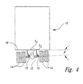
- Figure 4 is a rear view of a semi-tractor-trailer combination illustrating the placement of sensor units with the system of Figure 2A.
- Figure 5A is a rear view of a semi-tractor-trailer combination illustrating an alternative placement of sensor units with the system of Figure 2A.
- Figure 5B is a partial left side view of the semi-tractor-trailer combination of Figure 5A further illustrating the sensor placement and parameters measured by the system of Figure 2A.
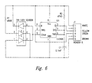
- Figure 6 is a schematic of one embodiment of a sensor unit used with the system of Figure 2A.
- a vehicle 10 such as a semi-tractor-trailer
- COG center of gravity
- the vehicle 10 includes an axle 12, tires 14, suspension system 15, and frame 18 to which various forces are applied.
- the various forces to the axle 12 cancel each other.
- the vehicle 10 in Figure 1B forces are applied to the axle 12 that are uncanceled.
- the vehicle 10 in Figure 1B is illustrated as executing a turn to the right.
- Such a turn causes a lateral acceleration thereby generating a roll moment about a roll axis 16. If the roll moment is sufficiently large, the tires 14 on the right side of the axle 12 lift off the ground and the vehicle 10 rolls over. As those skilled in the art can appreciate, the roll moment is dependent on both the lateral acceleration and the center of gravity. A high center of gravity will cause a greater roll moment than a low center of gravity. A large lateral acceleration causes a greater roll moment than a low lateral acceleration.
- the present invention uses sensors to measure the weight applied to each of the vehicle's drive wheels and to measure lateral acceleration. Based on these measurements, the system calculates the center of gravity of the vehicle and the lateral load transfer between the wheels of the axle 12.
- the present invention is embodied in a system 100, illustrated in the functional block diagram of Figure 2A that provides the vehicle operator with an indication of the height of center of gravity of the vehicle 10 and the lateral load transfer between the wheels of the axle 12.
- the system 100 may also be used as a monitor device to detect potentially dangerous driving habits of the vehicle operator. For example, the system 100 can monitor the lateral acceleration and lateral load transfer and, if the monitored parameters exceed a predetermined threshold, the system 100 can store the parameter values in a memory each time the predetermined threshold is exceeded.
- the memory can retain and display these data values at a later time.
- the system 100 may be installed on a school bus and monitored periodically, such as weekly.
- the memory can display the number of times during the previous week that the lateral acceleration and lateral load transfer exceeded the predetermined threshold. In this manner, potentially dangerous driving habits of the school bus driver may be detected and appropriate measures taken to prevent possible rollover accidents.
- the system 100 includes a central processing unit (CPU) 102, which may be a conventional microprocessor, embedded controller, or the like.
- a memory 104 may include both random access memory (RAM) and read-only memory (ROM).
- a roll moment calculator 105 calculates a roll moment of the vehicle 10.
- a center of gravity calculator 106 calculates a center of gravity of the vehicle 10. In an exemplary embodiment, the functions of roll moment calculator 105 and center of gravity calculator 106 are performed by the CPU 102.
- a display 108 provides the vehicle operator with indications of the center of gravity of the vehicle and of the lateral load transfer.
- the lateral load transfer is displayed as a ratio of the difference in the loads carried by the two sides of the axle 12 to the total axle load.
- a lateral load transfer ratio (LTR) of 1 indicates that the wheels on one side of the axle 12 are lifted off the ground.
- An LTR of -1 indicates that the wheels on the other side of the axle 12 are lifted off the ground.
- FIG. 2B illustrates one embodiment of the display 108.
- the load transfer ratio is displayed on a bar graph 150 having a substantially horizontal orientation to permit easy interpretation by the vehicle operator.
- the center of gravity height is displayed on a bar graph 152 having a substantially vertical orientation to permit easy interpretation by the vehicle operator.
- the display 108 is a color display, the load transfer ratio may be displayed on one color of below a predetermined threshold and displayed with a different color if above the predetermined threshold.
- An alternative embodiment of the display 108 is illustrated in Figure 2C where a conventional gauge, either digital or analog, displays the load transfer ratio.
- the center of gravity height may be displayed as a numeric read out in relative units, or absolute units, such as feet.
- the system 100 may also include an optional audio alarm 109 to provide an audible indication to the vehicle operator when the load transfer ratio exceeds predetermined threshold.
- the system 100 also includes an analog-to-digital converter (ADC) 110 that converts analog input data to digital form for processing by the CPU 102.
- ADC analog-to-digital converter
- the data digitized by the ADC 110 is filtered by a filter 112.
- the filter 112 presently employed by the system 100 is a digital low pass filter with a cut off frequency of 2 Hertz. The low cut off frequency serves to eliminate stray noise and to eliminate the effects of vibrations caused by natural resonances in the suspension system 15, which are typically around 10 Hertz.
- the system 100 also includes a gating circuit 114 and a sample/hold circuit 116 used to display the effective center of gravity.
- the effective center of gravity of the vehicle 10 is calculated based on measured parameters, including the lateral acceleration of the vehicle frame 18 (see Figures 1A and 1B).
- the gating circuit 114 provides an indication to the CPU 102 when the lateral acceleration is above a predetermined threshold.
- the CPU 102 thus calculates the effective center of gravity height only when the gating signal is applied, indicating that the lateral acceleration is above the predetermined threshold.
- the sample and hold circuit 116 uses the currently calculated effective center of gravity when the gating circuit 114 indicates that the lateral acceleration is above the predetermined threshold.
- the sample and hold circuit 116 retains the last calculated value for the effective center of gravity height when the gating circuit 114 indicates that the lateral acceleration is not above the predetermined threshold.
- the sample and hold circuit 116 updates the calculated effective center of gravity height when the lateral acceleration is above the predetermined threshold and stores the last valid calculated center of gravity measurement when the lateral acceleration is not above the predetermined threshold.
- the vehicle operator can manually depress a button (not shown) when the vehicle 10 is undergoing lateral acceleration to activate the gating circuit 114.
- the CPU 102 calculates the effective center of gravity in response to the manual activation of the gating circuit 114 via the button (not shown).
- the sample and hold circuit 116 stores the single value calculated by the CPU for the effective center of gravity height.
- the display 108 is configured to display the current lens and reflects light to the two photodiodes. When the sensor unit is level and the bubble is between the two photodiodes, the sensor produces a level indication. As the sensor unit is rotated, the bubble remains stationary and gradually redirects the light toward one photodiode and away from the other.
- the output of the sensor unit changes proportionately.
- the sensor output is linearly proportional to the amount of incident light.
- the output signal of the sensor unit is fed into the ADC 110 (see Figure 2A) to produce a pulse width modulated waveform which is sent to the CPU 102.
- the CPU 102 measures the width of the pulse and derives the absolute angular position of the sensor unit.
- Using a ratiometric photodiode circuit allows for a low cost ADC 110 that is insensitive to noise, temperature and other environmental factors.
- the sensor units are configured so that they produce a count value that indicates the relative tilt of the sensor. If the sensor unit is tilted so that the side with the cable coming out of it is lower than the opposite side, then the count will decrease indicating a negative angle or movement from the flat "zero" position. If the sensor unit is tilted in the other direction so that the cable side is higher than the opposite side, the count will increase indicating a positive angle or movement from the "zero" position.
- Each sensor unit is contained in a small box with a shielded cable leading to a central junction box (not shown).
- the junction box is then connected to the cab and power system of the vehicle 10.
- the junction box contains a small microprocessor (not shown) which measures each sensor unit in the manner described above and transmits the resulting data to the vehicle's cab for interface to the CPU 102.
- the CPU 102 processes data for both the sensor assembly 122 and the display 108.
- the sensor assembly 122 comprises two or more individual sensor units.
- Figure 6 is a schematic diagram of one sensor unit constructed in accordance with the '771 patent.
- the sensor unit contains an LED and two photodiodes mounted in proximity with the transparent cylindrical container. The output from the photodiodes is used to modulate the input of a TLC555 timer to produce a pulse-width modulated output signal.
- the operation of the TLC555 timer for value for the effective center of gravity height if the gating circuit 114 is active, and display the stored value in the sample and hold circuit 116 if the gating circuit 114 is not active.
- the various components are connected by a bus system 120, which may carry power, status signals, and control signals in addition to data.
- the filter 112, gating circuit 114, and sample and hold circuit 116 may be implemented by appropriate computer instructions stored in the memory 104 and executed by the CPU 102.
- the data storage area that is part of the sample and hold circuit 116 may be a storage register within the CPU 102 or a storage location in the memory 104.
- many components of the system 100 may be implemented by appropriate instructions executed by the CPU 102.
- Figure 2A illustrates these components as independent functional block since each performs a separate task.
- a sensor assembly 122 is used to provide data indicative of the load transfer and lateral acceleration.
- the sensor assembly 122 uses two or more independent sensor units such as the optical tilt sensor units illustrated in U.S. Patent No. 5,218,771 (the '771 patent), which is presently assigned to TV Interactive Data Corporation.
- the sensors described in that patent provide a low cost and rugged detection unit to indicate the orientation of the sensor unit. With one sensor mounted on the frame of the vehicle 10 and another mounted on the suspension, the roll angle of the frame relative to the axle can be determined. Other factors, such as the roll stiffness of the suspension, the truck mass, and the lateral acceleration can be used to calculate the center of gravity of the vehicle 10.
- the roll stiffness of the suspension, and the height of the roll center of the suspension are characteristics that can be estimated and entered into the system 100.
- each sensor unit contains a transparent cylindrical container with a bubble suspended in liquid.
- One end of the cylindrical container contains an infrared LED which illuminates the bubble.
- On both sides of the cylindrical container are photodiodes.
- the bubble acts like a reflective such purposes is well known and need not be described herein.
- the system 100 uses the orientation of two or more individual sensor units to provide an indication of lateral load transfer and lateral acceleration.
- the advantage of the orientation sensing apparatus of the '771 patent is its relatively low cost and ruggedness for operation in the hostile environment of the vehicle suspension system 15 (see Figures 1A and 1B).
- the liquid contained within the sensor units maintains a constant viscosity over the wide operating temperature range encountered by the vehicle 10. Furthermore, each sensor unit is self-contained and sealed, thus eliminating the adverse effects of contaminants such as dirt and water.
- the system 100 may be successfully implemented using a variety of sensors.
- the sensor assembly 122 may be comprised of two or more rotary variable differential transformer (RVDT) sensing units.
- RVDT rotary variable differential transformer
- an RVDT sensing unit generates an electrical signal that varies in response to the rotary position of a sensing element.
- Other types of sensor units useful in the system 100 include a rotary potentiometer, optical encoders, strain gauges, and the like.
- conventional computer input devices may also be used in the sensor assembly 122. For example, it is known in the use of multi-media computers to utilize a glove in which fiber optic cables are attached to fingers of the glove.
- a fiber optic system can be employed by the sensor assembly 122 to determine the tilt angle of the axle 12 and thus provide a measure of the lateral load transfer.
- a conventional accelerometer can provide an indication of lateral acceleration. The present invention is not limited by the specific form of the sensor assembly 122.
- the sensor assembly 122 is typically associated with the drive axle 12 of the vehicle 10. If the vehicle 10 is a tractor-trailer combination, the sensor assembly 122 is generally mounted on one of the drive axles of the tractor. However, multiple trailer combinations, sometimes called a train, are not uncommon on the roadway. With a multiple tractor-trailer combination, research has indicated that rollover accidents tend to begin initially with the axle of the rearmost trailer.
- the sensor assembly 122 may be associated with the axle of the rearmost trailer portion. It is also possible to mount a plurality of sensor assemblies 122 on one or more axles of the vehicle 10.
- the CPU 102 analyzes data from each of the sensor assemblies 122.
- the display 108 is configured to display only the greatest LTR calculated by the CPU 102.
- the basis for the estimation of both the height of the center of gravity and the lateral load transfer ratio is the measurement of the forces transferred between the tires 14 and the road. Direct measurement of these forces would require sensors located between the tires 14 and the road surface. Thus, while the direct measurement of forces is not possible, a free-body analysis of a single axle shows that the forces for that axle between the tires and the road may be inferred from the measurement of the forces and moments between the frame of the vehicle and the axle. From those measurements, the LTR and center of gravity may be calculated. The combination of the LTR and center of gravity can be used by the vehicle operator to determine the sensitivity of the vehicle 10 to a rollover. For example, a high center of gravity may result in vehicle rollover even at low lateral accelerations.
- a rollover occurs when a roll moment, applied to the vehicle through the roll center 16, exceeds the maximum moment which can be applied to the vehicle 10 by the road through the tires 14.
- the applied moment exceeds the maximum moment, the inside wheels of first one axle, then the rest of the axles in turn, lift off of the pavement and a rollover commences.
- Figure 3 illustrates the forces and moments acting upon one axle 12.
- the vectors V , H , and M represent the vertical forces, horizontal forces, and the moment, respectively, applied by the suspension system 15 (see Figures 1A and 1B) onto the axle 12.
- the vectors F l and F r represent the vertical forces applied to tires 14 on the left and right sides of the axle 12, respectively.
- the horizontal contact forces (i.e ., friction) between the tires 14 and the road surface are illustrated in Figure 3, but are not directly related to the present analysis.
- minor forces on the axle 12 itself are indicated by the vectors W and W a .
- the vector W indicates the weight of the axle 12, and the term W a indicates the centrifugal force exerted by the axle where a is the lateral acceleration, measured in "g's.”
- the forces exerted by the suspension on the axle 12 i . e ., V , H , and M ) are taken as acting through the roll center 16 of the suspension.
- the vertical tire forces i.e., F l and F r ) are taken as acting through the center of tire contact patches on each side of the axle 12, a distance T apart.
- Figure 3 illustrates the operation of forces with the assumption that the road surface is horizontal. However, the analysis applies where the road is sloped. In the case of a sloped road, the terms horizontal and vertical are interpreted as being parallel to and perpendicular to the local road slope.
- the center line of the axle 12 will generally be at an angle to the horizontal due to the flexibility of the tires 14 and the different loads carried by each side of the axle.
- Equation (4) defines the difference in tire contact forces.
- the sum of tire contact forces equals the sum of the vertical load V from the frame of the vehicle 10 and the weight W of the axle 12.
- F r + F l V + W where all terms have been previously defined.
- the weight W of the axle 12 is insignificant compared with the typical vertical load V .
- the CPU 102 uses the gating circuit 114 such that the effective height of the center of gravity h cgv is calculated only when the lateral acceleration a is above a predetermined threshold.
- equation (7) approximates the height of the center of gravity.
- Factors such as the rolling of the vehicle frame 18 (see Figures 1A and 1B), may cause a lateral shift that causes the calculated center of gravity to appear higher than the real center of gravity. However, such errors are considered minimal and may be disregarded.
- equation (7) provides a measure of the effective height of the center of gravity, which is a sufficiently close approximation to the real height of the center of gravity.
- the display 108 provides the vehicle operator with an indication of the LTR of the vehicle 10 and the effective center of gravity h cgv of the vehicle.
- equations (6) and (7) above are displayed for the vehicle operator.
- equations (4) and (5) must be solved.
- the height of the roll center h rc 16 of the vehicle 10 and the distance T between the contact patches of the tires 14 are fixed parameters that can be measured for a specific vehicle and will not change. Other parameters, such as the weight W of the axle 12, are fixed parameters, but may be safely ignored.
- variable parameters such as the roll moment M , the horizontal applied force H , and the vertical applied force V are measured by the sensor assembly 122.
- M the roll moment
- k s is a constant indicative of the roll stiffness of the suspension system
- ⁇ is an angle between the axle 12 and frame 18 of the vehicle 10
- C s is a constant indicative of the roll damping of the suspension
- d ⁇ / dt is the rate of change of ⁇ with respect to time.
- the angle ⁇ may be determined in several different manners.
- a first sensor unit S 1 is mounted on the frame 18 of the vehicle 10 while a second sensor unit S 2 is mounted on the axle 12.
- the first and second sensor units S 1 and S 2 provide an indication of the tilt angle of the frame 18 and the tilt angle of the axle 12, respectively.
- the configuration of the sensor assembly unit 122 in Figure 4 is sensitive to vibrations of the axle 12. These vibrations are considered to be noise and thus decrease the signal-to-noise ratio (SNR) of the measurements.
- the sensor assembly 122 (see Figure 2A) comprises the first sensor unit S 1 mounted on the frame 18, a second sensor unit S 2 mounted on a trailing arm 201 on the suspension system 15 of the vehicle 10 on the left side of the axle 12.
- a third sensor unit S 3 is mounted on a trailing arm 20r of the suspension system 15 of the vehicle 10 on the right side of the axle 12.
- the signals from the three sensor units S 1 , S 2 , S 3 are digitized by the ADC 110 (see Figure 2A) and processed by the CPU 102.
- the signals from the second sensor unit S 2 and third sensor unit S 3 are combined to form a differential signal.
- the differential signal generated by the CPU 102 further reduces the noise caused by road vibrations since both the second and third sensor units S 2 and S 3 are exposed to similar road vibrations.
- the differential signal also reduces error caused by other factors, such as road grade or braking of the vehicle 10 in such situations, both sensors S 2 and S 3 measure substantially the same tilt angle caused by the road grade or braking effects and produce a zero differential output signal in response to these external influences.
- the differential signal generated by the sensor units S 2 and S 3 provides a more accurate measure of the angle ⁇ than can be provided with a single sensor unit S 2 mounted directly on the axle 12 (see Figure 4).
- Figure 5B illustrates a side view of the differential sensor mounting and shows the second sensor unit S 2 mounted on the left trailing arm 201.
- the trailing arm 201 is pivotally attached to the frame 18 to define a variable angle ⁇ 1
- the third sensor unit S 3 is similarly mounted on the right trailing arm 20r (see Figure 5A).
- the right trailing arm 20r and the frame 18 define a variable angle ⁇ r .
- the horizontal distance between the pivot point coupling the trailing arms 201 and 20r to the axle 12 is illustrated in Figure 5B by the term e .
- the angle ⁇ between the axle 12 and the frame 18 is less than 10°, and, under normal conditions, is much less than 10°. Under such circumstances, the system 100 uses a linear approximation for the sine functions in equation (9).
- the calculated angle ⁇ and the rate of change of ⁇ with respect to time, d ⁇ / dt may be substituted into equation (8) to determine the roll moment M .
- the constant k s is a measure of suspension stiffness that depends on the geometry of the suspension system 15 (see Figures 1A and 1B). It should be noted that k s may vary slightly if the vehicle 10 uses an air suspension spring. However, such minor variation can be safely ignored.
- the constant C s is a measure of the roll damping of the suspension that depends on the geometry of the suspension system 15.
- the remaining variable parameter measured by the system 100 is the vertical force V exerted by the load of the vehicle 10 including the frame 18 and the load within the vehicle.
- a number of different techniques may be used to determine the vertical force V .
- the vehicle weight can be divided by the number of axles. While such measurements do not take into account the weight of the passengers, this weight is generally small compared to the vehicle weight itself
- vehicles such as tractor-trailer combinations, can measure the vertical force V using truck scales where each pair of axle sets is independently measured to derive the total vehicle weight.
- the measured weight for the axle associated with the sensor assembly 122 (see Figure 2A) is used for the value V .
- a direct measure of the vertical force V can be determined with an air spring suspension system by measuring the air pressure in the spring itself.
- the vertical force V equals the air pressure in the spring times the effective area of the spring. This value may be scaled by a constant indicative of the geometry of the air spring, such as the displacement distance of the air spring from the axle. Thus, a number of techniques may be successfully employed to determine the value for the vertical force V .
- the system 100 can readily calculate the load transfer ratio LTR using equations (4), (5) and (6) and the effective height of the center of gravity using equations (6) and (7).
- the system 100 advantageously provides a low cost and effective technique to provide the vehicle operator with an indication of the likelihood of the vehicle 10 to roll over. The vehicle operator can use this information to operate the vehicle more safely and thus reduce the occurrence of rollover accidents.
Landscapes
- Engineering & Computer Science (AREA)
- Mechanical Engineering (AREA)
- Aviation & Aerospace Engineering (AREA)
- Physics & Mathematics (AREA)
- General Physics & Mathematics (AREA)
- Vehicle Body Suspensions (AREA)
- Air Bags (AREA)
- Auxiliary Drives, Propulsion Controls, And Safety Devices (AREA)
Claims (50)
- System für die Erkennung von Fahrzeug (10) - Überrollbedingungen, und das System umfasst:einen Sensoraufbau (S1, S2 und S3), der mit dem Fahrzeug (10) gekoppelt ist und mindestens ein Signal erzeugt, welches bezeichnend für die Seitenbeschleunigung (a) des Fahrzeugs ist;eine Anzeige (108) für das Anzeigen der Wahrscheinlichkeit, dass das Fahrzeug (10) überrollt; unddas System ist gekennzeichnet durchden Sensoraufbau (S1, S2 und S3), der ferner mindestens ein Signal erzeugt, das bezeichnend ist für eine seitliche Lastverlagerung des Fahrzeugs;einen Rollmomentrechner (105), der mit dem Sensoraufbau (S1, S2 und S3) gekoppelt ist, um das Rollmoment (M) auf der Basis der Signale zu berechnen;einen Schwerpunktrechner (106), der mit dem Sensoraufbau (S1, S2 und S3) gekoppelt ist, um den Schwerpunkt des Fahrzeugs (10) auf der Basis des Rollmoments und der Seitenbeschleunigung (a) des Fahrzeugs zu berechnen;die Anzeige (108), die eine Rollmomentanzeige (150) enthält, und die mit dem Rollmomentrechner (105) gekoppelt ist, um eine visuelle Anzeige vorzusehen, die bezeichnend ist für das Rollmoment, und die eine Schwerpunktanzeige (152) enthält, um eine visuelle Anzeige vorzusehen, die bezeichnend ist für den effektiven Schwerpunkt des Fahrzeugs (10), um einen Hinweis vorzusehen auf die Wahrscheinlichkeit, dass das Fahrzeug (10) überrollt.
- System nach Anspruch 1, wobei der Rollmomentrechner (105) ein seitliches Lastverlagerungsverhältnis (LTR) berechnet, das bezeichnend ist für ein aktuelles Rollmoment verglichen mit einem maximalen Rollmoment, wobei die Rollmomentanzeige (150) das seitliche Lastverlagerungsverhältnis anzeigt.
- System nach Anspruch 1 oder 2, wobei das Fahrzeug (10) enthält: einen Körper (18) und ein Aufhängungssystem (15), das mit einer Fahrzeugachse (12) verbunden ist, und der Sensoraufbau (S1, S2 und S3) umfaßt eine erste, eine zweite und eine dritte Sensoreinheit, wobei die erste Sensoreinheit (S1) darauf ausgerichtet ist, um die Signale vorzusehen, die bezeichnend sind für die seitliche Beschleunigung des Fahrzeugkörpers (18), und die zweite und dritte Sensoreinheiten (S2 und S3) darauf ausgerichtet sind, um die Signale vorzusehen, die bezeichnend sind für die seitliche Lastverlagerung in dem Aufhängungssystem (15).
- System nach Anspruch 3, wobei die erste Sensoreinheit (S1) auf dem Fahrzeugkörper (18) montiert ist, um das Signal vorzusehen, das bezeichnend ist für die seitliche Beschleunigung.
- System nach Anspruch 3 oder 4, wobei die zweite und dritte Sensoreinheit (S2 und S3) an gegenüberliegenden Seiten der Fahrzeugachse (12) montiert sind, um die Signale vorzusehen, die bezeichnend sind für die seitliche Lastverlagerung von einer Seite der Fahrzeugachse (12) auf die gegenüberliegende Seite der Fahr zeugachse (12).
- System nach Anspruch 5, wobei der Rollmomentrechner (105) ein differentielles Signal aus den Signalen erzeugt, die von der zweiten und dritten Sensoreinheit (S2 und S3) erzeugt werden, um die seitliche Lastverlagerung zu bestimmen.
- System nach Anspruch 1 oder 2, wobei das Fahrzeug (10) enthält: einen Körper (18) und ein Aufhängungssystem (15), das mit einer Fahrzeugachse (12) verbunden ist, und der Sensoraufbau (S1 und S2) umfaßt eine erste und eine zweite Sensoreinheit, wobei die erste Sensoreinheit (S1) darauf ausgerichtet ist, um die Signale vorzusehen, die bezeichnend sind für die seitliche Beschleunigung des Fahrzeugkörpers (18), und die zweite Sensoreinheit (S2) darauf ausgerichtet ist, um einen Neigungswinkel in dem Aufhängungssystem (15) zu erkennen.
- System nach Anspruch 7, wobei die erste Sensoreinheit (S1) auf dem Fahrzeugkörper (18) montiert ist, um die seitliche Beschleunigung zu erkennen.
- System nach Anspruch 7, wobei die zweite Sensoreinheit (S2) auf der Fahrzeugachse (12) montiert ist, um den seitlichen Neigungswinkel der Fahrzeugachse (12) zu erkennen.
- System nach irgendeinem der Ansprüche 1 bis 9, wobei der Sensoraufbau (S1, S2 und S3) mindestens zwei optische Neigungssensoren enthält, die die Signale zu erzeugen in der Lage sind, die bezeichnend sind für die seitliche Beschleunigung und die seitliche Lastverlagerung.
- System nach irgendeinem der vorstehenden Ansprüche, wobei die Rollmoment(150) und Schwerpunktanzeige (152) eine erste bzw. eine zweite Balkendiagrammanzeige enthält, und die erste Balkendiagrammanzeige eine im Wesentlichen horizontale Anzeigeausrichtung hat, um die seitliche Lastverlagerung anzuzeigen, und die zweite Balkendiagrammanzeige eine im Wesentlichen vertikale Anzeigeausrichtung hat, um den berechneten, effektiven Schwerpunkt des Fahrzeugs anzuzeigen.
- System nach irgendeinem der Ansprüche 1 bis 10, wobei die Rollmomentanzeige (150) eine Farbanzeige ist, und die seitliche Lastverlagerung in einer ersten Farbe anzeigt, wenn die seitliche Lastverlagerung unterhalb von einem vorbestimmten Schwellwert ist, und die seitliche Lastverlagerung in einer zweiten Farbe anzeigt, wenn die seitliche Lastverlagerung oberhalb von dem vorbestimmten Schwellwert ist.
- System nach irgendeinem der vorstehenden Ansprüche, das ferner einen Audio-Wandler (109) enthält, um ein Warnsignal zu erzeugen, wenn die seitliche Lastverlagerung oberhalb von dem vorbestimmten Schwellwert ist.
- System nach irgendeinem der vorstehenden Ansprüche, wobei das Fahrzeug (10) eine Antriebsachse hat, und der Sensoraufbau (S1, S2 und S3) mit der Antriebsachse verbunden ist, um die seitliche Beschleunigung und die seitliche Lastverlagerung an der Antriebsachse zu erkennen.
- System nach irgendeinem der vorstehenden Ansprüche, wobei das Fahrzeug (10) ein Zugmaschinen-Anhänger-Gespann ist, das mindestens eine Antriebsachse hat, und der Sensoraufbau (S1, S2 und S3) in der Nähe der mindestens einen Antriebsachse montiert ist, um die Signale vorzusehen, die bezeichnend sind für die seitliche Beschleunigung und die seitliche Lastverlagerung an der mindestens einen Antriebsachse.
- System nach irgendeinem der vorstehenden Ansprüche, wobei das Fahrzeug (10) ein Zugmaschinen-Anhänger-Gespann ist, das eine Vielzahl von Anhänger-Abschnitten hat, die jeder eine Achse hat, und der Sensoraufbau (S1, S2 und S3) in der Nähe einer der Anhängerabschnittsachsen montiert ist, um die Signale vorzusehen, die bezeichnend sind für die seitliche Beschleunigung und die seitliche Lastverlagerung an der Anhängerabschnittsachse.
- System nach irgendeinem der vorstehenden Ansprüche, wobei das Fahrzeug (10) ein Zugmaschinen-Anhänger-Gespann ist, das eine Vielzahl von Anhänger-Abschnitten hat, die jeder eine Achse hat, und das System ferner eine Vielzahl von Sensoraufbauten hat, die in der Nähe von mindestens Zweien der Vielzahl von Anhängerabschnittsachsen montiert ist, um die Signale vorzusehen, die bezeichnend sind für die seitliche Beschleunigung und die seitliche Lastverlagerung an den Anhängerabschnittsachsen.
- System nach irgendeinem der vorstehenden Ansprüche, wobei das Fahrzeug (10) einen Körper (18) und ein Aufhängungssystem (15) hat, das mit einer Fahrzeugachse (12) verbunden ist, und der Rollmomentrechner (105) das Rollmoment durch Bestimmung eines Winkels berechnet, der zwischen dem Körper (18) und der Achse gebildet wird.
- System nach Anspruch 18, wobei das Aufhängungssystem (15) des Fahrzeugs (10) eine vorbestimmte Steifigkeit hat, und der Rollmomentrechner (105) das Rollmoment unter Verwendung eines Winkels, der zwischen dem Körper (18) und der Achse gebildet wird, und einer Konstanten berechnet, die bezeichnend ist für die vorbestimmte Steifigkeit des Aufhängungssystems.
- System nach irgendeinem der vorstehenden Ansprüche, das ferner eine Einrichtung für die Bestimmung einer statischen Last enthält, die auf das Fahrzeug wirkt, und der Rollmomentrechner (105) ferner ein Verhältnis der seitlichen Lastverlagerung und der statischen Last berechnet.
- System nach Anspruch 20, wobei die Rollmomentanzeige (150) eine Anzeige des Verhältnisses der seitlichen Lastverlagerung und der statischen Last vorsieht.
- System nach irgendeinem der vorstehenden Ansprüche, das ferner ein Torschaltungssignal einschließt, welches dem Schwerpunktrechner zugeführt wird, und der Schwerpunktrechner (106) den effektiven Schwerpunkt nur dann berechnet, wenn das Torschaltungssignal angelegt ist.
- System nach Anspruch 22, wobei das Torschaltungssignal an den Schwerpunktrechner (106) angelegt wird, wenn die seitliche Beschleunigung oberhalb von einem vorbestimmten Schwellwert ist.
- System nach Anspruch 22 oder 23, das ferner eine Datenspeicherungsstelle einschließt, um den berechneten Schwerpunkt zu speichern, wenn das Torschaltungssignal an den Schwerpunktrechner nicht angelegt ist, und die Schwerpunktanzeige (152) den errechneten Schwerpunkt anzeigt, wenn das Torschaltungssignal angelegt ist, und den gespeicherten Schwerpunkt anzeigt, wenn das Torschaltungssignal nicht angelegt ist.
- System nach irgendeinem der vorstehenden Ansprüche, das ferner eine Datenspeicherungsstelle einschließt, um einen Datenwert für das errechnete Rollmoment zu speichern, wenn das errechnete Rollmoment einen vorbestimmten Schwellwert überschreitet.
- System nach Anspruch 25, wobei die Datenspeicherungsstelle eine Vielzahl von errechneten Rollmomentwerten speichert, die bezeichnend sind für jedes Mal, an dem das errechnete Rollmoment den vorbestimmten Schwellwert übersteigt, und die Rollmomentanzeige (150) eine Anzeige für jeden der Vielzahl von errechneten Rollmomentwerten einschließt.
- System nach irgendeinem der vorstehenden Ansprüche, wobei der Rollmomentrechner (105) und der Schwerpunktrechner (106) Abschnitte eines einzigen Prozessors sind.
- System nach Anspruch 27, wobei die Rollmomentanzeige (150) und die Schwerpunktanzeige (152) Abschnitte einer einzigen Anzeige sind.
- System für die Erkennung von Fahrzeug (10) - Überrollbedingungen, und das System umfasst:einen Sensoraufbau (S1, S2 und S3), der mit dem Fahrzeug (10) gekoppelt ist und mindestens ein Signal erzeugt, welches bezeichnend für die Seitenbeschleunigung (a) des Fahrzeugs ist;eine Anzeige (108) für das Anzeigen der Wahrscheinlichkeit, dass das Fahrzeug (10) überrollt; unddas System ist gekennzeichnet durchden Sensoraufbau (S1, S2 und S3), der ferner mindestens ein Signal erzeugt, das bezeichnend ist für eine seitliche Lastverlagerung des Fahrzeugs (10);einen Schwerpunktprozessor (106), der mit dem Sensoraufbau (S1, S2 und S3) gekoppelt ist, um den effektiven Schwerpunkt des Fahrzeugs (10) zu berechnen;einen seitlichen Lastverlagerungsverhältnisprozessor, der mit dem Sensoraufbau (S1, S2 und S3) gekoppelt ist, um das seitliche Lastverlagerungsverhältnis (LTR) zu berechnen, das bezeichnend ist für eine aktuelle Lastverlagerung, verglichen mit einer maximalen seitlichen Lastverlagerung;die Anzeige, die eine seitliche Lastverlagerungsverhältnisanzeige (150) enthält, die mit dem seitlichen Lastverlagerungsverhältnisprozessor gekoppelt ist, um eine visuelle Anzeige vorzusehen, die bezeichnend ist für das seitliche Lastverlagerungsverhältnis, und die eine Schwerpunktanzeige (152) enthält, um eine visuelle Anzeige vorzusehen, die bezeichnend ist für den effektiven Schwerpunkt des Fahrzeugs (10), um einen Hinweis vorzusehen auf die Wahrscheinlichkeit, dass das Fahrzeug (10) überrollt.
- System nach Anspruch 29, wobei das Fahrzeug (10) enthält: einen Körper (18) und ein Aufhängungssystem (15), das mit einer Fahrzeugachse (12) verbunden ist, und der Sensoraufbau (S1, S2 und S3) umfaßt eine erste, eine zweite und eine dritte Sensoreinheit, wobei die erste Sensoreinheit (S1) darauf ausgerichtet ist, um die Signale vorzusehen, die bezeichnend sind für die seitliche Beschleunigung des Fahrzeugkörpers (18), und die zweite und dritte Sensoreinheiten (S2 und S3) darauf ausgerichtet sind, um die Signale vorzusehen, die bezeichnend sind für die seitliche Lastverlagerung in dem Aufhängungssystem (15).
- System nach Anspruch 30, wobei die erste Sensoreinheit (S1) auf dem Fahrzeugkörper (18) montiert ist, um die Signale vorzusehen, die bezeichnend sind für die seitliche Beschleunigung.
- System nach Anspruch 30 oder 31, wobei die zweite und dritte Sensoreinheit (S2 und S3) an gegenüberliegenden Seiten der Fahrzeugachse (12) montiert sind, um die Signale vorzusehen, die bezeichnend sind für die seitliche Lastverlagerung von einer Seite der Fahrzeugachse (12) auf die gegenüberliegende Seite der Fahrzeugachse (12).
- System nach Anspruch 32, wobei der seitliche Lastverlagerungsverhältnisprozessor ein differentielles Signal aus den Signalen erzeugt, die von der zweiten und dritten Sensoreinheit (S2 und S3) erzeugt werden, um die seitliche Lastverlagerung zu bestimmen.
- System nach irgendeinem der Ansprüche 29 bis 33, das ferner ein Torschaltungssignal einschließt, welches dem seitlichen Lastverlagerungsverhältnisprozessor zugeführt wird, und der seitliche Lastverlagerungsverhältnisprozessor den effektiven Schwerpunkt nur dann berechnet, wenn das Torschaltungssignal angelegt ist.
- System nach Anspruch 34, wobei das Torschaltungssignal an den seitlichen Lastverlagerungsverhältnisprozessor angelegt wird, wenn die seitliche Beschleunigung oberhalb von einem vorbestimmten Schwellwert ist.
- System nach Anspruch 34 oder 35, das ferner eine Datenspeicherungsstelle einschließt, um den berechneten Schwerpunkt zu speichern, wenn das Torschaltungssignal an den seitlichen Lastverlagerungsverhältnisprozessor nicht angelegt ist, und die Anzeige den errechneten Schwerpunkt anzeigt, wenn das Torschaltungssignal angelegt ist, und den gespeicherten Schwerpunkt anzeigt, wenn das Torschaltungssignal nicht angelegt ist.
- System nach irgendeinem der Ansprüche 29 bis 36, wobei der seitliche Lastverlagerungsverhältnisprozessor und der Schwerpunktrechner (106) Abschnitte eines einzigen Prozessors sind.
- System nach irgendeinem der Ansprüche 29 bis 37, wobei die seitliche Lastverlagerungsanzeige (150) und die Schwerpunktanzeige (152) Abschnitte einer einzigen Anzeige sind.
- Verfahren für die Erkennung von Fahrzeug (10) - Überrollbedingungen, und das Verfahren umfasst:wobei das Verfahren gekennzeichnet ist durchErzeugen eines Signals, das bezeichnend für die Seitenbeschleunigung (a) des Fahrzeugs (10) ist, unter Verwendung eines Sensoraufbaus (S1, S2 und S3), der mit dem Fahrzeug gekoppelt ist;Anzeigen von Daten auf einer Anzeige (108), die bezeichnend sind für ein Überrollen; undVerarbeiten des seitlichen Beschleunigungssignals, um einen Wert zu ermitteln, der bezeichnend ist für die Wahrscheinlichkeit eines Überrollens des Fahrzeugs (10);Erzeugen eines Signals, das bezeichnend ist für eine seitliche Lastverlagerung des Fahrzeugs unter Verwendung des Sensoraufbaus (S1, S2 und S3);Berechnen eines Rollmoments (M) auf der Basis der Signale, die bezeichnend sind für die seitliche Beschleunigung und Lastverlagerung;Berechnen eines effektiven Schwerpunkts des Fahrzeugs (10) auf der Basis des Rollmoments und der seitlichen Lastverlagerung des Fahrzeugs; undAnzeigen von Daten, die bezeichnend sind für das Rollmoment und den berechneten, effektiven Schwerpunkt des Fahrzeugs (10), um einen Hinweis vorzusehen auf die Wahrscheinlichkeit, dass das Fahrzeug (10) überrollt.
- Verfahren nach Anspruch 39, wobei der Schritt der Berechnung eines Rollmoments ein seitliches Lastverlagerungsverhältnis (LTR) berechnet, das bezeichnend ist für ein aktuelles Rollmoment verglichen mit einem maximalen Rollmoment, wobei der Schritt der Datenanzeige Daten anzeigt, die bezeichnend sind für das seitliche Lastverlagerungsverhältnis.
- Verfahren nach Anspruch 39 oder 40, wobei das Fahrzeug (10) enthält: einen Körper (18) und ein Aufhängungssystem (15), das mit einer Fahrzeugachse (12) verbunden ist, und der Sensoraufbau (S1, S2 und S3) umfaßt eine erste, eine zweite und eine dritte Sensoreinheit, wobei die erste Sensoreinheit (S1) darauf ausgerichtet ist, um die Signale vorzusehen, die bezeichnend sind für die seitliche Beschleunigung des Fahrzeugkörpers (18), und die zweite und dritte Sensoreinheiten (S2 und S3) darauf ausgerichtet sind, um die Signale vorzusehen, die bezeichnend sind für die seitliche Lastverlagerung in dem Aufhängungssystem (15), und der Schritt der Berechnung eines Rollmoments die Signale verwendet, die durch die erste, zweite und dritte Sensoreinheit erzeugt werden.
- Verfahren nach Anspruch 41, wobei die erste Sensoreinheit (S1) auf dem Fahrzeugkörper (18) montiert ist, um das Signal vorzusehen, das bezeichnend ist für die seitliche Beschleunigung.
- Verfahren nach Anspruch 41 oder 42, wobei die zweite und dritte Sensoreinheit (S2 und S3) an gegenüberliegenden Seiten der Fahrzeugachse (12) montiert sind, um die Signale vorzusehen, die bezeichnend sind für die seitliche Lastverlagerung von einer Seite der Fahrzeugachse (12) auf die gegenüberliegende Seite der Fahrzeugachse (12).
- Verfahren nach irgendeinem der Ansprüche 41 bis 43, wobei der Schritt der Berechnung des Rollmoments ein differentielles Signal aus den Signalen erzeugt, die von der zweiten und dritten Sensoreinheit (S2 und S3) erzeugt werden, um die seitliche Lastverlagerung zu bestimmen.
- Verfahren nach Anspruch 39 oder 40, wobei das Fahrzeug (10) einen Körper (18) und ein Aufhängungssystem (15) enthält, das mit einer Fahrzeugachse (12) verbunden ist, und der Sensoraufbau (S1, S2 und S3) eine erste und eine zweite Sensoreinheit umfaßt, wobei die erste Sensoreinheit (S1) darauf ausgerichtet ist, um die Signale vorzusehen, die bezeichnend sind für die seitliche Beschleunigung des Fahrzeugkörpers (18), und die zweite Sensoreinheit (S2) darauf ausgerichtet ist, um die Signale vorzusehen, die bezeichnend sind für die Lastverlagerung in dem Aufhängungssystem (15), und der Schritt der Berechnung eines Rollmoments die Signale verwendet, die durch die erste und zweite Sensoreinheit erzeugt werden.
- Verfahren nach Anspruch 45, wobei die erste Sensoreinheit (S1) auf dem Fahrzeugkörper (18) montiert ist, um die Signale vorzusehen, die bezeichnend sind für die seitliche Beschleunigung.
- Verfahren nach Anspruch 45 oder 46, wobei die zweite Sensoreinheit (S2) auf der Fahrzeugachse (12) montiert ist, um die Signale vorzusehen, die bezeichnend sind für die seitliche Lastverlagerung von einer Seite der Fahrzeugachse (12) auf die gegenüberliegende Seite der Fahrzeugachse (12).
- Verfahren nach irgendeinem der Ansprüche 39 bis 47, wobei der Sensoraufbau (S1, S2 und S3) mindestens zwei optische Neigungssensoren enthält, die die Signale zu erzeugen in der Lage sind, die bezeichnend sind für die seitliche Beschleunigung und die seitliche Lastverlagerung, und der Schritt der Berechnung des Rollmoments die Signale verwendet, die durch die optischen Neigungssensoren erzeugt werden.
- Verfahren nach irgendeinem der Ansprüche 39 bis 48, das ferner den Schritt enthält: Speicherung eines Datenwerts für das berechnete Rollmoment, falls das berechnete Rollmoment einen vorbestimmten Schwellwert übersteigt.
- Verfahren nach Anspruch 49, wobei der Schritt der Speicherung eine Vielzahl von berechneten Rollmomentdatenwerten speichert, die bezeichnend sind für jedes Mal, zu dem das berechnete Rollmoment den vorbestimmten Schwellwert übersteigt, und das Verfahren ferner den Schritt der Anzeige jedes der Vielzahl von berechneten Rollmomentwerten enthält.
Applications Claiming Priority (3)
| Application Number | Priority Date | Filing Date | Title |
|---|---|---|---|
| US763006 | 1996-12-10 | ||
| US08/763,006 US5825284A (en) | 1996-12-10 | 1996-12-10 | System and method for the detection of vehicle rollover conditions |
| PCT/US1997/022533 WO1998025779A1 (en) | 1996-12-10 | 1997-12-08 | System and method for the detection of vehicle rollover conditions |
Publications (2)
| Publication Number | Publication Date |
|---|---|
| EP0942839A1 EP0942839A1 (de) | 1999-09-22 |
| EP0942839B1 true EP0942839B1 (de) | 2001-10-04 |
Family
ID=25066641
Family Applications (1)
| Application Number | Title | Priority Date | Filing Date |
|---|---|---|---|
| EP97949791A Expired - Lifetime EP0942839B1 (de) | 1996-12-10 | 1997-12-08 | System und verfahren zur detektion von fahrzeugüberrollzuständen |
Country Status (9)
| Country | Link |
|---|---|
| US (1) | US5825284A (de) |
| EP (1) | EP0942839B1 (de) |
| JP (1) | JP2001507648A (de) |
| KR (1) | KR20000057486A (de) |
| CN (1) | CN1239919A (de) |
| AT (1) | ATE206368T1 (de) |
| CA (1) | CA2273950A1 (de) |
| DE (1) | DE69707148T2 (de) |
| WO (1) | WO1998025779A1 (de) |
Cited By (2)
| Publication number | Priority date | Publication date | Assignee | Title |
|---|---|---|---|---|
| EP3115263A4 (de) * | 2014-03-05 | 2017-11-01 | National University Corporation Tokyo University of Marine Science And Technology | Vorrichtung zur warnung vor überrollgefahr |
| EP3659890A4 (de) * | 2017-11-09 | 2021-03-17 | Gree Electric Appliances (Wuhan) Co., Ltd. | Warnverfahren zur vermeidung von fahrzeugüberrollen, vorrichtung, speichermedium und fahrzeug |
Families Citing this family (255)
| Publication number | Priority date | Publication date | Assignee | Title |
|---|---|---|---|---|
| US8229624B2 (en) * | 1995-06-07 | 2012-07-24 | American Vehicular Sciences Llc | Vehicle diagnostic information generating and transmission systems and methods |
| US8060282B2 (en) * | 1995-06-07 | 2011-11-15 | Automotive Technologies International, Inc. | Vehicle component control methods and systems based on vehicle stability |
| US8157047B2 (en) | 1995-06-07 | 2012-04-17 | Automotive Technologies International, Inc. | Occupant protection systems control techniques |
| US20080046149A1 (en) * | 1995-06-07 | 2008-02-21 | Automotive Technologies International, Inc. | Vehicle Component Control Methods and Systems Based on Vehicle Stability |
| DE19602879C1 (de) * | 1996-01-29 | 1997-08-07 | Knorr Bremse Systeme | Verfahren zum Erfassen der Gefahr des Umkippens eines Fahrzeuges |
| US6202488B1 (en) * | 1996-12-13 | 2001-03-20 | Trw Inc. | Vehicle rollover sensor |
| US6554293B1 (en) * | 1997-12-16 | 2003-04-29 | Continental Teves Ag & Co., Ohg | Method for improving tilt stability in a motor vehicle |
| US6002975A (en) * | 1998-02-06 | 1999-12-14 | Delco Electronics Corporation | Vehicle rollover sensing |
| US6038495A (en) * | 1998-02-06 | 2000-03-14 | Delco Electronics Corporation | Vehicle rollover sensing using short-term integration |
| US6002974A (en) * | 1998-02-06 | 1999-12-14 | Delco Electronics Corporation | Vehicle rollover sensing using extended kalman filter |
| JP2002503185A (ja) * | 1998-04-07 | 2002-01-29 | ロベルト・ボッシュ・ゲゼルシャフト・ミト・ベシュレンクテル・ハフツング | 車両の安定化方法および装置 |
| DE19823093C2 (de) * | 1998-05-22 | 2000-06-08 | Daimler Chrysler Ag | Vorrichtung zur Bestimmung von fahrzeugspezifischen Größen eines Fahrzeuges während der Fahrt |
| US6185489B1 (en) * | 1998-06-12 | 2001-02-06 | Roger Dean Strickler | Vehicle overturn monitor |
| DE19828338A1 (de) * | 1998-06-25 | 1999-12-30 | Bosch Gmbh Robert | Verfahren zum Ermitteln einer zu einem Überrollvorgang führenden kritischen Winkellage eines Fahrzeugs |
| WO2000003900A1 (de) * | 1998-07-17 | 2000-01-27 | Continental Teves Ag & Co. Ohg | Verfahren und vorrichtung zum bestimmen und erkennen der kippgefahr eines fahrzeuges |
| DE19844542A1 (de) * | 1998-09-29 | 2000-03-30 | Bosch Gmbh Robert | Vorrichtung und Verfahren zum Begrenzen einer Rückrollgeschwindigkeit eines Kraftfahrzeuges |
| JP3072730B2 (ja) * | 1998-10-09 | 2000-08-07 | 日本電気株式会社 | 車両検出方法および装置 |
| DE19904908C2 (de) | 1999-02-06 | 2001-03-01 | Daimler Chrysler Ag | Einrichtung zur Abstandsbestimmung zwischen Fahrzeugaufbau und Fahrzeugrad |
| US6397133B1 (en) | 1999-04-19 | 2002-05-28 | Palmer Safety Systems, Llc | Vehicle rollover safety system |
| DE19918597C2 (de) * | 1999-04-23 | 2001-03-08 | Deutsch Zentr Luft & Raumfahrt | Verfahren zur Reduktion der Kippgefahr von Straßenfahrzeugen |
| NL1011873C2 (nl) * | 1999-04-23 | 2000-10-24 | Tno | Kantelwaarschuwingssysteem voor voertuigen. |
| US6301536B1 (en) * | 1999-11-18 | 2001-10-09 | Visteon Global Technologies, Inc. | Method and apparatus for detecting a vehicle rollover |
| DE19958221A1 (de) * | 1999-12-02 | 2001-06-07 | Wabco Gmbh & Co Ohg | Verfahren zur Verhinderung des Umkippens eines Fahrzeugs |
| US6262658B1 (en) * | 1999-12-17 | 2001-07-17 | Intel Corporation | Tipping indicator |
| US6324446B1 (en) | 1999-12-21 | 2001-11-27 | Ford Global Technologies, Inc. | Roll over stability control for an automotive vehicle |
| US6332104B1 (en) | 1999-12-21 | 2001-12-18 | Ford Global Technologies, Inc. | Roll over detection for an automotive vehicle |
| US6834218B2 (en) | 2001-11-05 | 2004-12-21 | Ford Global Technologies, Llc | Roll over stability control for an automotive vehicle |
| US6263261B1 (en) | 1999-12-21 | 2001-07-17 | Ford Global Technologies, Inc. | Roll over stability control for an automotive vehicle |
| US6452487B1 (en) * | 2000-02-14 | 2002-09-17 | Stanley Krupinski | System and method for warning of a tip over condition in a tractor trailer or tanker |
| US6417767B1 (en) * | 2000-03-27 | 2002-07-09 | Craig D. Carlson | Device and system for indicating rapid deceleration in vehicles |
| US6290019B1 (en) | 2000-04-18 | 2001-09-18 | Trw Inc. | System and method for vehicle side rollover aversion |
| US6507016B1 (en) | 2000-04-18 | 2003-01-14 | Trw Inc. | Apparatus and method for sensing a vehicle rollover condition |
| US6282474B1 (en) | 2000-06-04 | 2001-08-28 | Ford Global Technologies, Inc. | Method and apparatus for detecting rollover of an automotive vehicle |
| US6327526B1 (en) | 2000-08-02 | 2001-12-04 | Ford Global Technologies, Inc. | Method and apparatus for measuring the rollover resistance and compliance characteristics of a vehicle |
| DE10046036A1 (de) * | 2000-09-18 | 2002-03-28 | Knorr Bremse Systeme | Verfahren zum Abschätzen der Umkippgefahr eines Fahrzeugs |
| US6456194B1 (en) * | 2000-09-21 | 2002-09-24 | Craig D. Carlson | Device and method for sensing and indicating inclination of an automotive vehicle |
| US6397127B1 (en) * | 2000-09-25 | 2002-05-28 | Ford Global Technologies, Inc. | Steering actuated wheel lift identification for an automotive vehicle |
| US7233236B2 (en) | 2000-09-25 | 2007-06-19 | Ford Global Technologies, Llc | Passive wheel lift identification for an automotive vehicle using operating input torque to wheel |
| US7109856B2 (en) | 2000-09-25 | 2006-09-19 | Ford Global Technologies, Llc | Wheel lifted and grounded identification for an automotive vehicle |
| US7132937B2 (en) | 2000-09-25 | 2006-11-07 | Ford Global Technologies, Llc | Wheel lift identification for an automotive vehicle using passive and active detection |
| US6904350B2 (en) | 2000-09-25 | 2005-06-07 | Ford Global Technologies, Llc | System for dynamically determining the wheel grounding and wheel lifting conditions and their applications in roll stability control |
| US6356188B1 (en) * | 2000-09-25 | 2002-03-12 | Ford Global Technologies, Inc. | Wheel lift identification for an automotive vehicle |
| US6495820B1 (en) | 2000-10-02 | 2002-12-17 | Trw Inc. | Sensor apparatus and method for sensing angular rotation of an object using light reflected off a rotor and bifurcation compensation |
| US6498976B1 (en) * | 2000-10-30 | 2002-12-24 | Freightliner Llc | Vehicle operator advisor system and method |
| US6584388B2 (en) | 2001-11-08 | 2003-06-24 | Delphi Technologies, Inc. | Adaptive rollover detection apparatus and method |
| US6542792B2 (en) | 2000-11-29 | 2003-04-01 | Delphi Technologies, Inc. | Vehicle rollover detection apparatus and method |
| US6437701B1 (en) * | 2000-12-18 | 2002-08-20 | Caterpillar Inc. | Apparatus and method for a machine stability system for an articulated work machine |
| US6600414B2 (en) * | 2000-12-20 | 2003-07-29 | Trw Inc. | Apparatus and method for detecting vehicle rollover having a discriminating safing function |
| US6433681B1 (en) * | 2000-12-20 | 2002-08-13 | Trw Inc. | Apparatus and method for detecting vehicle rollover having roll-rate switched threshold |
| US6542073B2 (en) | 2000-12-20 | 2003-04-01 | Trw Inc. | System and method for sensing vehicle rollover |
| JP3788286B2 (ja) * | 2001-01-19 | 2006-06-21 | トヨタ自動車株式会社 | 乗員保護装置の制御装置 |
| US6799092B2 (en) | 2001-02-21 | 2004-09-28 | Ford Global Technologies, Llc | Rollover stability control for an automotive vehicle using rear wheel steering and brake control |
| US6529811B2 (en) | 2001-03-01 | 2003-03-04 | Automotive Systems Laboratory, Inc. | Vehicle rollover detection system |
| US6535800B2 (en) | 2001-05-29 | 2003-03-18 | Delphi Technologies, Inc. | Vehicle rollover sensing using angular rate sensors |
| DE10130407A1 (de) * | 2001-06-23 | 2003-01-02 | Daimler Chrysler Ag | Verfahren zur Vermeidung von Überrollvorgängen an Sattel-Anhängern |
| US6985795B2 (en) | 2001-09-21 | 2006-01-10 | Schlage Lock Company | Material handler with center of gravity monitoring system |
| US6654674B2 (en) | 2001-11-21 | 2003-11-25 | Ford Global Technologies, Llc | Enhanced system for yaw stability control system to include roll stability control function |
| KR100418680B1 (ko) * | 2001-11-23 | 2004-02-11 | 기아자동차주식회사 | 내리막길에서의 코너링시 위험을 경보하는 장치 및 방법 |
| DE10161799A1 (de) * | 2001-12-15 | 2003-06-26 | Man Nutzfahrzeuge Ag | Verfahren zur On Board Ermittlung des wirkenden Kippmomentes und/oder der aktuellen Schwerpunkthöhe eines Fahrzeuges |
| US6654671B2 (en) | 2002-02-15 | 2003-11-25 | Delphi Technologies, Inc. | Vehicle rollover detection having variable sensitivity |
| US6556908B1 (en) | 2002-03-04 | 2003-04-29 | Ford Global Technologies, Inc. | Attitude sensing system for an automotive vehicle relative to the road |
| US6938716B1 (en) | 2002-03-18 | 2005-09-06 | Schwing America, Inc. | Concrete mixing truck anti-rollover system |
| CN100352703C (zh) * | 2002-03-19 | 2007-12-05 | 汽车系统实验室公司 | 车辆倾翻检测系统 |
| WO2003081179A2 (en) * | 2002-03-19 | 2003-10-02 | Automotive Systems Laboratory, Inc. | Vehicle rollover detection system |
| US6918600B2 (en) | 2002-04-23 | 2005-07-19 | Barksdale, Inc. | Electronic control of vehicle air suspension |
| US20060267296A1 (en) * | 2002-04-23 | 2006-11-30 | Dodd C I | Electronic control of vehicle air suspension |
| US6741922B2 (en) * | 2002-05-30 | 2004-05-25 | Bendix Commercial Vehicle Systems Llc | Antilock braking system based roll over prevention |
| US6941205B2 (en) | 2002-08-01 | 2005-09-06 | Ford Global Technologies, Llc. | System and method for deteching roll rate sensor fault |
| US7302331B2 (en) | 2002-08-01 | 2007-11-27 | Ford Global Technologies, Inc. | Wheel lift identification for an automotive vehicle |
| US7003389B2 (en) | 2002-08-01 | 2006-02-21 | Ford Global Technologies, Llc | System and method for characterizing vehicle body to road angle for vehicle roll stability control |
| US7085639B2 (en) | 2002-08-01 | 2006-08-01 | Ford Global Technologies, Llc | System and method for characterizing the road bank for vehicle roll stability control |
| US7194351B2 (en) | 2002-08-01 | 2007-03-20 | Ford Global Technologies, Llc | System and method for determining a wheel departure angle for a rollover control system |
| US7079928B2 (en) | 2002-08-01 | 2006-07-18 | Ford Global Technologies, Llc | System and method for determining a wheel departure angle for a rollover control system with respect to road roll rate and loading misalignment |
| US7430468B2 (en) | 2002-08-05 | 2008-09-30 | Ford Global Technologies, Llc | System and method for sensitizing the activation criteria of a rollover control system |
| US7085642B2 (en) | 2002-08-05 | 2006-08-01 | Ford Global Technologies, Llc | Method and system for correcting sensor offsets |
| US6963797B2 (en) | 2002-08-05 | 2005-11-08 | Ford Global Technologies, Llc | System and method for determining an amount of control for operating a rollover control system |
| US20040024505A1 (en) | 2002-08-05 | 2004-02-05 | Salib Albert Chenouda | System and method for operating a rollover control system in a transition to a rollover condition |
| US20040024504A1 (en) | 2002-08-05 | 2004-02-05 | Salib Albert Chenouda | System and method for operating a rollover control system during an elevated condition |
| US6961648B2 (en) | 2002-08-05 | 2005-11-01 | Ford Motor Company | System and method for desensitizing the activation criteria of a rollover control system |
| DE10239406A1 (de) * | 2002-08-28 | 2004-03-11 | Robert Bosch Gmbh | Vorrichtung zur Erkennung eines Fahrzeugüberschlags |
| DE10247993B4 (de) * | 2002-10-15 | 2011-02-17 | Robert Bosch Gmbh | Verfahren und Vorrichtung zur Ermittlung der Schwerpunkthöhe eines Kraftfahrzeugs |
| US20040133365A1 (en) * | 2002-11-05 | 2004-07-08 | Drumm Stefan A. | Method of determining forces and torques acting on a riding vehicle |
| SE525248C2 (sv) * | 2003-02-18 | 2005-01-11 | Scania Cv Ab | Arrangemang och förfarande för att uppskatta tyngdpunktshöjden hos ett fordon |
| US9162656B2 (en) | 2003-02-26 | 2015-10-20 | Ford Global Technologies, Llc | Active driven wheel lift identification for an automotive vehicle |
| US7239949B2 (en) | 2003-02-26 | 2007-07-03 | Ford Global Technologies, Llc | Integrated sensing system |
| US7653471B2 (en) | 2003-02-26 | 2010-01-26 | Ford Global Technologies, Llc | Active driven wheel lift identification for an automotive vehicle |
| DE10319443A1 (de) * | 2003-04-30 | 2004-11-18 | Robert Bosch Gmbh | Vorrichtung zur Ansteuerung von Rückhaltemitteln |
| US7136731B2 (en) | 2003-06-11 | 2006-11-14 | Ford Global Technologies, Llc | System for determining vehicular relative roll angle during a potential rollover event |
| JP4145741B2 (ja) * | 2003-07-03 | 2008-09-03 | 三菱電機株式会社 | 車両のロールオーバ判別装置および車両のロールオーバ判別方法 |
| US20060265108A1 (en) * | 2003-07-11 | 2006-11-23 | Martin Kieren | Vehicle dynamics regulation system adapted to the rolling behaviour of a vehicle |
| US20050033549A1 (en) * | 2003-07-25 | 2005-02-10 | Siemens Vdo Automotive Corporation | Rollover sensing using tire pressure sensor |
| US20050036560A1 (en) * | 2003-08-14 | 2005-02-17 | Adc Dsl Systems, Inc. | Cable calculator |
| DE10338879A1 (de) * | 2003-08-23 | 2005-03-17 | Wabco Gmbh & Co.Ohg | Verfahren zur Abschätzung einer Querbeschleunigung eines Fahrzeugs |
| US7145442B1 (en) * | 2003-10-14 | 2006-12-05 | Yu Hei Sunny Wai | Vehicle operation display system |
| DE102004006696A1 (de) * | 2003-10-24 | 2005-06-02 | Robert Bosch Gmbh | An den Beladungszustand eines Fahrzeugs angepasstes Fahrdynamikreglungssystem |
| CN100554016C (zh) * | 2003-10-24 | 2009-10-28 | 罗伯特.博世有限公司 | 与车辆装载状况相匹配的行驶动力学调节系统 |
| US6983583B2 (en) * | 2003-11-21 | 2006-01-10 | Ariens Company | Lawnmower tilt sensor apparatus and method |
| US7512461B2 (en) * | 2003-11-25 | 2009-03-31 | Delphi Technologies, Inc. | Vehicle rollover sensing using angular accelerometer |
| JP2005178420A (ja) * | 2003-12-16 | 2005-07-07 | Honda Motor Co Ltd | 不整地走行用鞍乗り型車両 |
| US7162340B2 (en) * | 2004-01-08 | 2007-01-09 | Delphi Technologies, Inc. | Vehicle rollover detection and method of anticipating vehicle rollover |
| DE102004003718A1 (de) * | 2004-01-24 | 2005-08-11 | Conti Temic Microelectronic Gmbh | Verfahren und Vorrichtung zum Auslösen eines Insassenschutzsystems |
| US7502675B2 (en) | 2004-04-01 | 2009-03-10 | Delphi Technologies, Inc. | Feedforward control of motor vehicle roll angle |
| US7308350B2 (en) | 2004-05-20 | 2007-12-11 | Ford Global Technologies, Llc | Method and apparatus for determining adaptive brake gain parameters for use in a safety system of an automotive vehicle |
| US7451032B2 (en) | 2004-06-02 | 2008-11-11 | Ford Global Technologies, Llc | System and method for determining desired yaw rate and lateral velocity for use in a vehicle dynamic control system |
| US7403848B2 (en) * | 2004-08-16 | 2008-07-22 | Delphi Technologies, Inc. | Vehicle rollover detection method |
| US7191047B2 (en) | 2004-09-27 | 2007-03-13 | Delphi Technologies, Inc. | Motor vehicle control using a dynamic feedforward approach |
| US7640081B2 (en) | 2004-10-01 | 2009-12-29 | Ford Global Technologies, Llc | Roll stability control using four-wheel drive |
| US7715965B2 (en) | 2004-10-15 | 2010-05-11 | Ford Global Technologies | System and method for qualitatively determining vehicle loading conditions |
| US7668645B2 (en) | 2004-10-15 | 2010-02-23 | Ford Global Technologies | System and method for dynamically determining vehicle loading and vertical loading distance for use in a vehicle dynamic control system |
| US7239952B2 (en) * | 2004-12-08 | 2007-07-03 | Continental Teves, Inc. | Reduced order parameter identification for vehicle rollover control system |
| US7660654B2 (en) | 2004-12-13 | 2010-02-09 | Ford Global Technologies, Llc | System for dynamically determining vehicle rear/trunk loading for use in a vehicle control system |
| US7557697B2 (en) * | 2005-02-22 | 2009-07-07 | Continental Teves, Inc. | System to measure wheel liftoff |
| FR2884311A1 (fr) * | 2005-04-12 | 2006-10-13 | Renault Sas | Procede d'estimation de la pente et du devers d'une route a partir d'un vehicule automobile, et dispositif de mise en oeuvre |
| US7480547B2 (en) | 2005-04-14 | 2009-01-20 | Ford Global Technologies, Llc | Attitude sensing system for an automotive vehicle relative to the road |
| DE102005021721A1 (de) * | 2005-05-11 | 2006-11-16 | Zf Friedrichshafen Ag | Verfahren zum Steuern von Fahrfunktionen eines Fahrzeuges |
| US20070017715A1 (en) * | 2005-07-20 | 2007-01-25 | Mccann Gerard O | Bogie slider control system and method utilizing trailer weight information |
| US7477972B2 (en) | 2005-08-01 | 2009-01-13 | Delphi Technologies, Inc. | Rollover warning and detection method for transport vehicles |
| US7590481B2 (en) | 2005-09-19 | 2009-09-15 | Ford Global Technologies, Llc | Integrated vehicle control system using dynamically determined vehicle conditions |
| US7600826B2 (en) | 2005-11-09 | 2009-10-13 | Ford Global Technologies, Llc | System for dynamically determining axle loadings of a moving vehicle using integrated sensing system and its application in vehicle dynamics controls |
| US8121758B2 (en) | 2005-11-09 | 2012-02-21 | Ford Global Technologies | System for determining torque and tire forces using integrated sensing system |
| US7526376B2 (en) * | 2005-12-02 | 2009-04-28 | Gm Global Technology Operations, Inc. | In-vehicle determination of the relative center of gravity height |
| US10878646B2 (en) | 2005-12-08 | 2020-12-29 | Smartdrive Systems, Inc. | Vehicle event recorder systems |
| US20070150138A1 (en) | 2005-12-08 | 2007-06-28 | James Plante | Memory management in event recording systems |
| US8359146B2 (en) * | 2005-12-15 | 2013-01-22 | Bendix Commercial Vehicle Systems Llc | Single channel roll stability system |
| JP4811089B2 (ja) * | 2006-02-02 | 2011-11-09 | いすゞ自動車株式会社 | 車両の横転危険度判定装置 |
| WO2007098891A1 (en) * | 2006-03-03 | 2007-09-07 | National University Of Ireland Maynooth | Method for determining the centre of gravity for an automotive vehicle |
| US9201842B2 (en) | 2006-03-16 | 2015-12-01 | Smartdrive Systems, Inc. | Vehicle event recorder systems and networks having integrated cellular wireless communications systems |
| US8996240B2 (en) | 2006-03-16 | 2015-03-31 | Smartdrive Systems, Inc. | Vehicle event recorders with integrated web server |
| US7571030B2 (en) * | 2006-04-10 | 2009-08-04 | Gm Global Technology Operations, Inc. | Estimation of vehicle roll rate and roll angle using suspension deflection sensors |
| US7873454B2 (en) * | 2006-05-03 | 2011-01-18 | Eaton Corporation | Method of identifying predictive lateral load transfer ratio for vehicle rollover prevention and warning systems |
| US8269617B2 (en) * | 2009-01-26 | 2012-09-18 | Drivecam, Inc. | Method and system for tuning the effect of vehicle characteristics on risk prediction |
| US8508353B2 (en) * | 2009-01-26 | 2013-08-13 | Drivecam, Inc. | Driver risk assessment system and method having calibrating automatic event scoring |
| US8849501B2 (en) * | 2009-01-26 | 2014-09-30 | Lytx, Inc. | Driver risk assessment system and method employing selectively automatic event scoring |
| US9067565B2 (en) | 2006-05-22 | 2015-06-30 | Inthinc Technology Solutions, Inc. | System and method for evaluating driver behavior |
| US8630768B2 (en) | 2006-05-22 | 2014-01-14 | Inthinc Technology Solutions, Inc. | System and method for monitoring vehicle parameters and driver behavior |
| US7805231B2 (en) * | 2006-06-29 | 2010-09-28 | Delphi Technologies, Inc. | Integrated vehicle crash sensing system and method |
| DE102006045304A1 (de) * | 2006-09-26 | 2008-04-03 | Siemens Ag | Verfahren und Vorrichtung zur Schwerpunkthöhenschätzung eines Fahrzeugs |
| DE102006045303B3 (de) * | 2006-09-26 | 2008-02-07 | Siemens Ag | Verfahren und Vorrichtung zur Absolutneigungserkennung eines Fahrzeugs |
| US7899610B2 (en) | 2006-10-02 | 2011-03-01 | Inthinc Technology Solutions, Inc. | System and method for reconfiguring an electronic control unit of a motor vehicle to optimize fuel economy |
| US8989959B2 (en) | 2006-11-07 | 2015-03-24 | Smartdrive Systems, Inc. | Vehicle operator performance history recording, scoring and reporting systems |
| US8649933B2 (en) | 2006-11-07 | 2014-02-11 | Smartdrive Systems Inc. | Power management systems for automotive video event recorders |
| US8868288B2 (en) | 2006-11-09 | 2014-10-21 | Smartdrive Systems, Inc. | Vehicle exception event management systems |
| US8483942B2 (en) | 2006-11-22 | 2013-07-09 | National University Corporatioin Tokyo University of Marine Science and Technology | System for detecting or estimating center-of-gravity, lateral rollover limit or cargo weight |
| GB0623802D0 (en) | 2006-11-29 | 2007-01-10 | Brown Duncan | An arrangement of interconnected devices or system to indicate loading state or overload of the axles on a vehicle |
| US20080319606A1 (en) * | 2007-02-19 | 2008-12-25 | Fortson Frederick O | Vehicle rollover detection and prevention system |
| US8019514B2 (en) * | 2007-02-28 | 2011-09-13 | Caterpillar Inc. | Automated rollover prevention system |
| GB2448691B (en) * | 2007-04-23 | 2010-03-10 | Knorr Bremse Systeme | Tilt Angle Sensor for Stability Control of a Vehicle |
| US7573375B2 (en) * | 2007-05-02 | 2009-08-11 | Paccar Inc | Rollover prediction and warning method |
| US8239092B2 (en) | 2007-05-08 | 2012-08-07 | Smartdrive Systems Inc. | Distributed vehicle event recorder systems having a portable memory data transfer system |
| US8825277B2 (en) | 2007-06-05 | 2014-09-02 | Inthinc Technology Solutions, Inc. | System and method for the collection, correlation and use of vehicle collision data |
| US7922196B2 (en) * | 2007-06-11 | 2011-04-12 | Ford Global Technologies, Llc | Sensor integration for airbag deployment |
| US8666590B2 (en) | 2007-06-22 | 2014-03-04 | Inthinc Technology Solutions, Inc. | System and method for naming, filtering, and recall of remotely monitored event data |
| US9129460B2 (en) | 2007-06-25 | 2015-09-08 | Inthinc Technology Solutions, Inc. | System and method for monitoring and improving driver behavior |
| US7999670B2 (en) | 2007-07-02 | 2011-08-16 | Inthinc Technology Solutions, Inc. | System and method for defining areas of interest and modifying asset monitoring in relation thereto |
| US8577703B2 (en) | 2007-07-17 | 2013-11-05 | Inthinc Technology Solutions, Inc. | System and method for categorizing driving behavior using driver mentoring and/or monitoring equipment to determine an underwriting risk |
| US9117246B2 (en) | 2007-07-17 | 2015-08-25 | Inthinc Technology Solutions, Inc. | System and method for providing a user interface for vehicle mentoring system users and insurers |
| US8818618B2 (en) | 2007-07-17 | 2014-08-26 | Inthinc Technology Solutions, Inc. | System and method for providing a user interface for vehicle monitoring system users and insurers |
| US7876205B2 (en) | 2007-10-02 | 2011-01-25 | Inthinc Technology Solutions, Inc. | System and method for detecting use of a wireless device in a moving vehicle |
| DE102007051218A1 (de) * | 2007-10-26 | 2009-04-30 | Volkswagen Ag | Verfahren und Regelungssystem/Regelungskomponente zur Bestimmung von dynamischen Nick-, Wank- und/oder Hubachsen |
| GB2454223B (en) * | 2007-11-01 | 2011-09-21 | Haldex Brake Products Ltd | Vehicle stability control method |
| EP2072294A1 (de) * | 2007-12-18 | 2009-06-24 | Iveco S.p.A. | Verfahren und System zum Erfassen der Last eines mit nichtpneumatischen Aufhängungen ausgestatteten Fahrzeugs |
| US8019511B2 (en) * | 2008-05-22 | 2011-09-13 | Ford Global Technologies, Llc | Vehicle rollover detection |
| US8688180B2 (en) | 2008-08-06 | 2014-04-01 | Inthinc Technology Solutions, Inc. | System and method for detecting use of a wireless device while driving |
| DE102008049174B4 (de) * | 2008-09-26 | 2013-11-14 | Staude & Company | Verfahren zur Ansteuerung des elektronischen Stabilitätsprogramms (ESP) von Fahrzeuganhängern |
| US8854199B2 (en) * | 2009-01-26 | 2014-10-07 | Lytx, Inc. | Driver risk assessment system and method employing automated driver log |
| US8963702B2 (en) | 2009-02-13 | 2015-02-24 | Inthinc Technology Solutions, Inc. | System and method for viewing and correcting data in a street mapping database |
| US8892341B2 (en) | 2009-02-13 | 2014-11-18 | Inthinc Technology Solutions, Inc. | Driver mentoring to improve vehicle operation |
| US8188887B2 (en) | 2009-02-13 | 2012-05-29 | Inthinc Technology Solutions, Inc. | System and method for alerting drivers to road conditions |
| US8700260B2 (en) | 2009-03-30 | 2014-04-15 | Lord Corporation | Land vehicles and systems with controllable suspension systems |
| WO2011004459A1 (ja) * | 2009-07-07 | 2011-01-13 | トヨタ自動車株式会社 | 車両制御装置及び演算装置 |
| JP5279678B2 (ja) * | 2009-10-19 | 2013-09-04 | 本田技研工業株式会社 | 可搬式作業機 |
| WO2011143377A1 (en) * | 2010-05-14 | 2011-11-17 | Lord Corporation | Land vehicles and systems with controllable suspension systems |
| JP5733533B2 (ja) * | 2010-05-21 | 2015-06-10 | 国立大学法人東京海洋大学 | 重心検知装置 |
| CN101967883B (zh) * | 2010-09-09 | 2012-02-22 | 安徽星马汽车股份有限公司 | 一种泵车防倾翻控制电路 |
| CN102756686B (zh) * | 2011-04-26 | 2015-07-29 | 贵州大学 | 预警车辆侧翻的方法和装置 |
| JP5709655B2 (ja) * | 2011-06-07 | 2015-04-30 | 日野自動車株式会社 | 表示装置、車両、および表示方法、並びにプログラム |
| DE102011111862A1 (de) * | 2011-08-31 | 2013-02-28 | Wabco Gmbh | Verfahren zur Warnung des Fahrers eines Fahrzeuges vor einem drohenden Umkippen und Steuerungseinrichtung dafür |
| US8606492B1 (en) | 2011-08-31 | 2013-12-10 | Drivecam, Inc. | Driver log generation |
| US8744642B2 (en) | 2011-09-16 | 2014-06-03 | Lytx, Inc. | Driver identification based on face data |
| US8996234B1 (en) | 2011-10-11 | 2015-03-31 | Lytx, Inc. | Driver performance determination based on geolocation |
| US9298575B2 (en) | 2011-10-12 | 2016-03-29 | Lytx, Inc. | Drive event capturing based on geolocation |
| GB2497134B8 (en) | 2011-12-02 | 2014-07-23 | Caterpiller Sarl | Determing the relative orientation of members of an articulated work machine |
| US8989914B1 (en) | 2011-12-19 | 2015-03-24 | Lytx, Inc. | Driver identification based on driving maneuver signature |
| CN102529960B (zh) * | 2012-02-15 | 2015-04-15 | 三一汽车制造有限公司 | 防侧翻的控制方法、控制系统及搅拌运输车 |
| US9240079B2 (en) | 2012-04-17 | 2016-01-19 | Lytx, Inc. | Triggering a specialized data collection mode |
| US8676428B2 (en) | 2012-04-17 | 2014-03-18 | Lytx, Inc. | Server request for downloaded information from a vehicle-based monitor |
| CN103419589A (zh) * | 2012-05-24 | 2013-12-04 | 昆达电脑科技(昆山)有限公司 | 车身偏侧角度感测装置 |
| US9728228B2 (en) | 2012-08-10 | 2017-08-08 | Smartdrive Systems, Inc. | Vehicle event playback apparatus and methods |
| WO2014028594A2 (en) * | 2012-08-14 | 2014-02-20 | The Trustees Of Columbia University In The City Of New York | Imaging interfaces for full finger and full hand optical tomography |
| CN102901550B (zh) * | 2012-11-15 | 2014-08-13 | 陕西电器研究所 | 一种实现车载动态称重的方法 |
| US9344683B1 (en) | 2012-11-28 | 2016-05-17 | Lytx, Inc. | Capturing driving risk based on vehicle state and automatic detection of a state of a location |
| KR101410647B1 (ko) * | 2012-11-28 | 2014-06-24 | 현대자동차주식회사 | 차량 전복 방지 시스템 |
| DE102014201668B4 (de) | 2013-03-07 | 2021-09-02 | Ford Global Technologies, Llc | Seitlich neigbares, mehrspuriges Fahrzeug |
| DE102014201670A1 (de) | 2013-03-07 | 2014-09-11 | Ford Global Technologies, Llc | Seitlich neigbares, mehrspuriges Fahrzeug |
| DE102014201127B4 (de) | 2013-03-07 | 2022-02-03 | Ford Global Technologies, Llc | Seitlich neigbares, mehrspuriges Fahrzeug |
| DE102014201632B4 (de) | 2013-03-07 | 2021-09-02 | Ford Global Technologies, Llc | Seitlich neigbares, mehrspuriges Fahrzeug |
| DE102014201630B4 (de) | 2013-03-07 | 2021-09-02 | Ford Global Technologies, Llc | Seitlich neigbares, mehrspuriges Fahrzeug |
| US12491943B1 (en) | 2013-03-10 | 2025-12-09 | Oshkosh Defense, Llc | Systems and methods for a military vehicle |
| US10752075B1 (en) * | 2017-04-28 | 2020-08-25 | Oshkosh Defense, Llc | Systems and methods for determining vehicle characteristics |
| US9303715B2 (en) | 2013-03-10 | 2016-04-05 | Oshkosh Defense, Llc | Limiting system for a vehicle suspension component |
| FR3003834B1 (fr) | 2013-03-26 | 2015-04-24 | Univ Blaise Pascal Clermont Ii | Procede de reduction du risque de basculement d'un vehicule automoteur equipe d'un systeme de suspension pilotable |
| CN103213582B (zh) * | 2013-04-18 | 2016-08-24 | 上海理工大学 | 基于车身侧倾角估计的防侧翻预警控制方法 |
| US8990000B2 (en) | 2013-04-23 | 2015-03-24 | Ford Global Technologies, Llc | Active suspension with load detection and adaptation |
| DE102013014819A1 (de) | 2013-09-10 | 2015-03-12 | Wabco Gmbh | Verfahren zur Stabilisierung des Fahrverhaltens eines Fahrzeuggespanns und Fahrdynamikregeleinrichtung |
| US9501878B2 (en) | 2013-10-16 | 2016-11-22 | Smartdrive Systems, Inc. | Vehicle event playback apparatus and methods |
| US9172477B2 (en) | 2013-10-30 | 2015-10-27 | Inthinc Technology Solutions, Inc. | Wireless device detection using multiple antennas separated by an RF shield |
| US9610955B2 (en) | 2013-11-11 | 2017-04-04 | Smartdrive Systems, Inc. | Vehicle fuel consumption monitor and feedback systems |
| US9128113B2 (en) | 2014-01-27 | 2015-09-08 | Nissan North America, Inc. | Vehicle orientation indicator |
| GB2523185B (en) * | 2014-02-18 | 2017-03-08 | Caterpillar Sarl | Method of determining whether a frame of a work machine is approaching a tip over point |
| US8892310B1 (en) | 2014-02-21 | 2014-11-18 | Smartdrive Systems, Inc. | System and method to detect execution of driving maneuvers |
| US9283825B2 (en) | 2014-02-25 | 2016-03-15 | Isam Mousa | System, method, and apparatus to prevent commercial vehicle rollover |
| US9862341B2 (en) * | 2014-06-09 | 2018-01-09 | Nitin Govind RAM | Two-wheeler airbag system |
| CN104006974B (zh) * | 2014-06-12 | 2016-03-30 | 四川省农业机械研究设计院 | 手扶式田园作业机械爬坡过埂特征性能检测装置 |
| DE102014217246B3 (de) | 2014-08-29 | 2015-12-24 | Ford Global Technologies, Llc | Stabilisierungsanordnung für ein Neigefahrwerk eines Fahrzeugs |
| KR101568147B1 (ko) * | 2014-08-29 | 2016-07-20 | (주)지니정보통신 | 차량 상태 모니터링 시스템 및 그의 처리 방법 |
| DE102014217386B4 (de) | 2014-09-01 | 2024-11-14 | Ford Global Technologies, Llc | Verfahren zum Betrieb eines Neigefahrwerks für ein schienenungebundenes Fahrzeug |
| US9663127B2 (en) | 2014-10-28 | 2017-05-30 | Smartdrive Systems, Inc. | Rail vehicle event detection and recording system |
| US11618376B2 (en) | 2014-10-30 | 2023-04-04 | Crc R&D, Llc | Methods, apparatuses, and systems for monitoring state of a transportation system |
| US9914392B2 (en) * | 2014-10-30 | 2018-03-13 | Cross Road Centers, Llc | Methods, apparatuses, and systems for monitoring state of a transportation system |
| US11069257B2 (en) | 2014-11-13 | 2021-07-20 | Smartdrive Systems, Inc. | System and method for detecting a vehicle event and generating review criteria |
| US10076939B2 (en) | 2014-11-26 | 2018-09-18 | Ford Global Technologies, Llc | Suspension systems for laterally tiltable multitrack vehicles |
| CN104842736B (zh) * | 2014-12-22 | 2017-02-22 | 北汽福田汽车股份有限公司 | 一种用于测试车辆行驶过程中车辆姿态的方法及系统 |
| US9919640B2 (en) * | 2015-01-13 | 2018-03-20 | Mark Allen BUCKINGHAM | System and method for controlling dollies |
| CN104535153B (zh) * | 2015-01-23 | 2017-04-19 | 重庆大唐科技股份有限公司 | 轮胎识别器与轴识别器组合装置 |
| US9925843B2 (en) | 2015-02-24 | 2018-03-27 | Ford Global Technologies, Llc | Rear suspension systems for laterally tiltable multitrack vehicles |
| US10023019B2 (en) | 2015-02-24 | 2018-07-17 | Ford Global Technologies, Llc | Rear suspension systems with rotary devices for laterally tiltable multitrack vehicles |
| EP3072846A1 (de) * | 2015-03-25 | 2016-09-28 | DANA ITALIA S.p.A | System und verfahren zur erkennung eines drohenden umkippens eines fahrzeugs |
| US9679420B2 (en) | 2015-04-01 | 2017-06-13 | Smartdrive Systems, Inc. | Vehicle event recording system and method |
| RU2587775C1 (ru) * | 2015-04-14 | 2016-06-20 | Федеральное Государственное Бюджетное Образовательное Учреждение Высшего Профессионального Образования "Донской Государственный Технический Университет" (Дгту) | Устройство для повышения прочности кузова транспортного средства при опрокидывании |
| US10479159B2 (en) | 2016-04-04 | 2019-11-19 | Barksdale, Inc. | Ride height leveling with selectable configurations: system and method |
| JP6866744B2 (ja) * | 2017-04-17 | 2021-04-28 | いすゞ自動車株式会社 | 重心高推定装置 |
| KR102048829B1 (ko) | 2017-12-28 | 2019-11-26 | 주식회사 지에스엠 | 차축 부착형 차량 축하중 센서모듈 |
| KR102051967B1 (ko) * | 2018-01-31 | 2019-12-04 | 충남대학교산학협력단 | 트랙터의 전복 경고방법 및 장치 |
| US11364920B2 (en) * | 2018-05-01 | 2022-06-21 | Ford Global Technologies, Llc | Methods and apparatus to compensate for body roll in vehicle weight calculations |
| CN108973899A (zh) * | 2018-08-12 | 2018-12-11 | 苏州青科艾莉电子科技有限公司 | 一种空气悬架系统控制方法和空气悬架系统 |
| CN109367462B (zh) * | 2018-09-21 | 2021-06-18 | 中国重汽集团青岛重工有限公司 | 自卸车稳定性安全控制系统及方法 |
| US11458796B2 (en) | 2018-09-24 | 2022-10-04 | Zoox, Inc. | Controlling vehicle suspension system using pressure set point |
| KR102140980B1 (ko) | 2018-12-17 | 2020-08-04 | 주식회사 지에스엠 | 차량의 축하중을 측정하기 위한 센서모듈의 설치구조 |
| GB2580035A (en) * | 2018-12-19 | 2020-07-15 | Haldex Brake Prod Ab | Vehicle stability apparatus and method |
| EP3943341A4 (de) * | 2019-03-19 | 2022-12-14 | Hitachi Construction Machinery Co., Ltd. | Ladeflächenhebe- und -absenkvorrichtung eines muldenkippers |
| KR102719868B1 (ko) * | 2019-04-23 | 2024-10-23 | 현대자동차주식회사 | 차량 및 그 제어방법 |
| US11397116B2 (en) | 2019-05-13 | 2022-07-26 | Driving Innovations, LLC | Load sensor system with improved assembly connection |
| AT522647A1 (de) * | 2019-06-13 | 2020-12-15 | Siemens Mobility Austria Gmbh | Verfahren und Vorrichtung zur betrieblichen Neigungsbestimmung bei Fahrzeugen |
| CN110667568B (zh) * | 2019-09-24 | 2021-11-30 | 江苏徐工工程机械研究院有限公司 | 一种翻车警报系统、翻车风险预测方法及翻车警报方法 |
| CN114728558A (zh) * | 2019-11-22 | 2022-07-08 | 沃尔沃卡车集团 | 用于监测车辆负载分布的方法和系统 |
| KR102244449B1 (ko) | 2019-12-09 | 2021-04-26 | 주식회사 지에스엠 | 차축 부착형 차량 축하중 센서모듈 구조 |
| CN110962841B (zh) * | 2019-12-20 | 2022-01-14 | 重庆长安工业(集团)有限责任公司深圳分公司 | 车辆控制方法及相关产品 |
| US11549241B2 (en) * | 2019-12-23 | 2023-01-10 | Caterpillar Paving Products Inc. | Machine slope and pitch control based on dynamic center of gravity |
| DE102020111915B3 (de) * | 2020-05-04 | 2021-06-24 | Dr. Ing. H.C. F. Porsche Aktiengesellschaft | Verfahren zur Ermittlung von Fahrzeugkenngrößen |
| KR102464434B1 (ko) | 2020-12-29 | 2022-11-09 | 주식회사 지에스엠 | 차축의 표면 연마장치 |
| KR20230071849A (ko) * | 2021-11-15 | 2023-05-24 | 현대자동차주식회사 | 군집 주행 제어 장치 및 그 방법 |
| CN115158282B (zh) * | 2022-06-28 | 2024-06-18 | 一汽奔腾轿车有限公司 | 一种降低车辆高速行驶中横摆失控风险的主动安全系统 |
| CN115635849B (zh) * | 2022-11-16 | 2025-04-04 | 东风华神汽车有限公司 | 一种基于ecas进行显示控制的仪表 |
| EP4494902A1 (de) * | 2023-07-21 | 2025-01-22 | Firma iQnexxt.solutions GmbH | Fahrzeuganhänger mit einem sensor zur messung und/oder ermittlung der durch die ladung auf die achse des fahrzeuganhängers wirkenden achslast |
| CN116878927B (zh) * | 2023-09-06 | 2023-12-08 | 山东梁山华宇集团汽车制造有限公司 | 一种用于挂车的运行状态检测系统 |
Family Cites Families (20)
| Publication number | Priority date | Publication date | Assignee | Title |
|---|---|---|---|---|
| US4078224A (en) * | 1976-06-25 | 1978-03-07 | Mize Lawrence A | Electronic roll warning system for vehicles |
| GB2088606B (en) * | 1980-12-03 | 1984-12-05 | Motor Industry Research Ass Th | Roll-over warning device |
| JPS58152793A (ja) * | 1982-03-05 | 1983-09-10 | ティー・シー・エム株式会社 | 運搬車両の横転防止装置 |
| GB8304884D0 (en) * | 1983-02-22 | 1983-03-23 | Trw Probe Electronics Co Ltd | Rollover warning system |
| US4737759A (en) * | 1984-09-24 | 1988-04-12 | Transgard, Inc. | Level warning device |
| JPS61172080A (ja) * | 1985-01-28 | 1986-08-02 | Nissan Motor Co Ltd | 超音波測定装置 |
| US4682145A (en) * | 1985-05-03 | 1987-07-21 | Brawner Jr Clarence A | Truck level sensing and indicating system |
| US4658508A (en) * | 1986-01-30 | 1987-04-21 | Cardel, Inc. | Electronic level measuring systems for truck trailers |
| JPH0694253B2 (ja) * | 1986-03-17 | 1994-11-24 | トヨタ自動車株式会社 | 車輌用ロ−ル制御装置 |
| JPS63116918A (ja) * | 1986-11-05 | 1988-05-21 | Kayaba Ind Co Ltd | ロ−ル制御機構 |
| US5032821A (en) * | 1989-05-12 | 1991-07-16 | Domanico Edward J | Motor vehicle stability monitoring and alarm system and method |
| JP3056749B2 (ja) * | 1989-05-15 | 2000-06-26 | 富士重工業株式会社 | 車両用アクテイブサスペンションの制御装置 |
| JP2745239B2 (ja) * | 1990-04-16 | 1998-04-28 | 稚晴 中村 | 横転防止装置 |
| JP2708629B2 (ja) * | 1990-11-26 | 1998-02-04 | 日野自動車工業株式会社 | 車両用横転限界報知装置 |
| JPH05124543A (ja) * | 1991-10-31 | 1993-05-21 | Isuzu Motors Ltd | トラツク横転防止装置 |
| US5218771A (en) * | 1992-04-15 | 1993-06-15 | Redford Peter M | Orientation sensing apparatus |
| FR2689463A1 (fr) * | 1992-04-06 | 1993-10-08 | Varet Pierre | Système qui évite le renversement des poids lourds. |
| US5383680A (en) * | 1992-12-21 | 1995-01-24 | Cadillac Gage Textron Inc. | Anti-roll system for wheeled vehicles |
| JPH06297985A (ja) * | 1993-04-19 | 1994-10-25 | Toyota Motor Corp | 車両の制御装置 |
| NL9400843A (nl) * | 1994-05-24 | 1996-01-02 | Tno | Stelsel voor het bepalen van de stabiliteit van een voertuig. |
-
1996
- 1996-12-10 US US08/763,006 patent/US5825284A/en not_active Expired - Fee Related
-
1997
- 1997-12-08 JP JP52687998A patent/JP2001507648A/ja active Pending
- 1997-12-08 WO PCT/US1997/022533 patent/WO1998025779A1/en not_active Ceased
- 1997-12-08 AT AT97949791T patent/ATE206368T1/de not_active IP Right Cessation
- 1997-12-08 KR KR1019990705147A patent/KR20000057486A/ko not_active Withdrawn
- 1997-12-08 DE DE69707148T patent/DE69707148T2/de not_active Expired - Fee Related
- 1997-12-08 CN CN97180531A patent/CN1239919A/zh active Pending
- 1997-12-08 EP EP97949791A patent/EP0942839B1/de not_active Expired - Lifetime
- 1997-12-08 CA CA002273950A patent/CA2273950A1/en not_active Abandoned
Cited By (3)
| Publication number | Priority date | Publication date | Assignee | Title |
|---|---|---|---|---|
| EP3115263A4 (de) * | 2014-03-05 | 2017-11-01 | National University Corporation Tokyo University of Marine Science And Technology | Vorrichtung zur warnung vor überrollgefahr |
| US10377330B2 (en) | 2014-03-05 | 2019-08-13 | National University Corporation Tokyo University Of Marine Science And Technology | Lateral rollover risk warning device |
| EP3659890A4 (de) * | 2017-11-09 | 2021-03-17 | Gree Electric Appliances (Wuhan) Co., Ltd. | Warnverfahren zur vermeidung von fahrzeugüberrollen, vorrichtung, speichermedium und fahrzeug |
Also Published As
| Publication number | Publication date |
|---|---|
| JP2001507648A (ja) | 2001-06-12 |
| EP0942839A1 (de) | 1999-09-22 |
| DE69707148D1 (de) | 2001-11-08 |
| CA2273950A1 (en) | 1998-06-18 |
| DE69707148T2 (de) | 2002-03-07 |
| ATE206368T1 (de) | 2001-10-15 |
| US5825284A (en) | 1998-10-20 |
| KR20000057486A (ko) | 2000-09-15 |
| CN1239919A (zh) | 1999-12-29 |
| WO1998025779A1 (en) | 1998-06-18 |
Similar Documents
| Publication | Publication Date | Title |
|---|---|---|
| EP0942839B1 (de) | System und verfahren zur detektion von fahrzeugüberrollzuständen | |
| CA2630152C (en) | Rollover prediction and warning method | |
| JP3116310B2 (ja) | 坂走行を検出する装置 | |
| US5032821A (en) | Motor vehicle stability monitoring and alarm system and method | |
| CA2461084C (en) | Vehicle stability operator feedback system | |
| US6452487B1 (en) | System and method for warning of a tip over condition in a tractor trailer or tanker | |
| US6498976B1 (en) | Vehicle operator advisor system and method | |
| US6363331B1 (en) | Weight distribution monitor | |
| AU700446B2 (en) | Vehicle traveling control device | |
| US5973273A (en) | Method for determining weight of a vehicle in motion | |
| US20020038193A1 (en) | Measurement of the load status of a motor vehicle | |
| US6588769B2 (en) | Vehicle roll control | |
| EP1226986B1 (de) | Beladungsschätzer | |
| KR20000070352A (ko) | 차량의 기울기상태 검출 방법 및 장치 | |
| EP1085993A1 (de) | Wanksteuerung für ein fahrzeug | |
| GB2257403A (en) | Road vehicle stability indicating system. | |
| GB2348508A (en) | Tow coupling sensor assemblies | |
| GB2313203A (en) | Measurement of vehicle loading | |
| JPH1054751A (ja) | 貨物自動車の積載量を計量するシステム | |
| US20040254702A1 (en) | Method and apparatus for sensing a turn on a vehicle | |
| JPS60500856A (ja) | 転覆警報システム | |
| JP3009098B2 (ja) | 車両の積載重量計測装置 | |
| KR101410647B1 (ko) | 차량 전복 방지 시스템 | |
| EP1454773A2 (de) | Verfahren und Vorrichtung zum Detektieren eines Druckabfalls im Reifen | |
| GB2222560A (en) | Road vehicle stability indicating system |
Legal Events
| Date | Code | Title | Description |
|---|---|---|---|
| PUAI | Public reference made under article 153(3) epc to a published international application that has entered the european phase |
Free format text: ORIGINAL CODE: 0009012 |
|
| 17P | Request for examination filed |
Effective date: 19990608 |
|
| AK | Designated contracting states |
Kind code of ref document: A1 Designated state(s): AT BE CH DE DK ES FI FR GB GR IE IT LI LU MC NL PT SE |
|
| 17Q | First examination report despatched |
Effective date: 19990920 |
|
| GRAG | Despatch of communication of intention to grant |
Free format text: ORIGINAL CODE: EPIDOS AGRA |
|
| GRAG | Despatch of communication of intention to grant |
Free format text: ORIGINAL CODE: EPIDOS AGRA |
|
| GRAG | Despatch of communication of intention to grant |
Free format text: ORIGINAL CODE: EPIDOS AGRA |
|
| GRAH | Despatch of communication of intention to grant a patent |
Free format text: ORIGINAL CODE: EPIDOS IGRA |
|
| GRAH | Despatch of communication of intention to grant a patent |
Free format text: ORIGINAL CODE: EPIDOS IGRA |
|
| GRAA | (expected) grant |
Free format text: ORIGINAL CODE: 0009210 |
|
| AK | Designated contracting states |
Kind code of ref document: B1 Designated state(s): AT BE CH DE DK ES FI FR GB GR IE IT LI LU MC NL PT SE |
|
| PG25 | Lapsed in a contracting state [announced via postgrant information from national office to epo] |
Ref country code: NL Free format text: LAPSE BECAUSE OF FAILURE TO SUBMIT A TRANSLATION OF THE DESCRIPTION OR TO PAY THE FEE WITHIN THE PRESCRIBED TIME-LIMIT Effective date: 20011004 Ref country code: LI Free format text: LAPSE BECAUSE OF FAILURE TO SUBMIT A TRANSLATION OF THE DESCRIPTION OR TO PAY THE FEE WITHIN THE PRESCRIBED TIME-LIMIT Effective date: 20011004 Ref country code: IT Free format text: LAPSE BECAUSE OF FAILURE TO SUBMIT A TRANSLATION OF THE DESCRIPTION OR TO PAY THE FEE WITHIN THE PRE;WARNING: LAPSES OF ITALIAN PATENTS WITH EFFECTIVE DATE BEFORE 2007 MAY HAVE OCCURRED AT ANY TIME BEFORE 2007. THE CORRECT EFFECTIVE DATE MAY BE DIFFERENT FROM THE ONE RECORDED.SCRIBED TIME-LIMIT Effective date: 20011004 Ref country code: FI Free format text: LAPSE BECAUSE OF FAILURE TO SUBMIT A TRANSLATION OF THE DESCRIPTION OR TO PAY THE FEE WITHIN THE PRESCRIBED TIME-LIMIT Effective date: 20011004 Ref country code: CH Free format text: LAPSE BECAUSE OF FAILURE TO SUBMIT A TRANSLATION OF THE DESCRIPTION OR TO PAY THE FEE WITHIN THE PRESCRIBED TIME-LIMIT Effective date: 20011004 Ref country code: BE Free format text: LAPSE BECAUSE OF FAILURE TO SUBMIT A TRANSLATION OF THE DESCRIPTION OR TO PAY THE FEE WITHIN THE PRESCRIBED TIME-LIMIT Effective date: 20011004 Ref country code: AT Free format text: LAPSE BECAUSE OF FAILURE TO SUBMIT A TRANSLATION OF THE DESCRIPTION OR TO PAY THE FEE WITHIN THE PRESCRIBED TIME-LIMIT Effective date: 20011004 |
|
| REF | Corresponds to: |
Ref document number: 206368 Country of ref document: AT Date of ref document: 20011015 Kind code of ref document: T |
|
| REG | Reference to a national code |
Ref country code: CH Ref legal event code: EP |
|
| REF | Corresponds to: |
Ref document number: 69707148 Country of ref document: DE Date of ref document: 20011108 |
|
| REG | Reference to a national code |
Ref country code: IE Ref legal event code: FG4D |
|
| PGFP | Annual fee paid to national office [announced via postgrant information from national office to epo] |
Ref country code: SE Payment date: 20011120 Year of fee payment: 5 |
|
| PGFP | Annual fee paid to national office [announced via postgrant information from national office to epo] |
Ref country code: GB Payment date: 20011122 Year of fee payment: 5 |
|
| PGFP | Annual fee paid to national office [announced via postgrant information from national office to epo] |
Ref country code: DE Payment date: 20011123 Year of fee payment: 5 |
|
| PG25 | Lapsed in a contracting state [announced via postgrant information from national office to epo] |
Ref country code: MC Free format text: LAPSE BECAUSE OF NON-PAYMENT OF DUE FEES Effective date: 20011208 Ref country code: LU Free format text: LAPSE BECAUSE OF NON-PAYMENT OF DUE FEES Effective date: 20011208 |
|
| PG25 | Lapsed in a contracting state [announced via postgrant information from national office to epo] |
Ref country code: IE Free format text: LAPSE BECAUSE OF FAILURE TO SUBMIT A TRANSLATION OF THE DESCRIPTION OR TO PAY THE FEE WITHIN THE PRESCRIBED TIME-LIMIT Effective date: 20011210 |
|
| REG | Reference to a national code |
Ref country code: GB Ref legal event code: IF02 |
|
| PG25 | Lapsed in a contracting state [announced via postgrant information from national office to epo] |
Ref country code: PT Free format text: LAPSE BECAUSE OF FAILURE TO SUBMIT A TRANSLATION OF THE DESCRIPTION OR TO PAY THE FEE WITHIN THE PRESCRIBED TIME-LIMIT Effective date: 20020104 Ref country code: DK Free format text: LAPSE BECAUSE OF FAILURE TO SUBMIT A TRANSLATION OF THE DESCRIPTION OR TO PAY THE FEE WITHIN THE PRESCRIBED TIME-LIMIT Effective date: 20020104 |
|
| PG25 | Lapsed in a contracting state [announced via postgrant information from national office to epo] |
Ref country code: GR Free format text: LAPSE BECAUSE OF FAILURE TO SUBMIT A TRANSLATION OF THE DESCRIPTION OR TO PAY THE FEE WITHIN THE PRESCRIBED TIME-LIMIT Effective date: 20020105 |
|
| ET | Fr: translation filed | ||
| NLV1 | Nl: lapsed or annulled due to failure to fulfill the requirements of art. 29p and 29m of the patents act | ||
| REG | Reference to a national code |
Ref country code: CH Ref legal event code: PL |
|
| PG25 | Lapsed in a contracting state [announced via postgrant information from national office to epo] |
Ref country code: ES Free format text: LAPSE BECAUSE OF FAILURE TO SUBMIT A TRANSLATION OF THE DESCRIPTION OR TO PAY THE FEE WITHIN THE PRESCRIBED TIME-LIMIT Effective date: 20020430 |
|
| PLBE | No opposition filed within time limit |
Free format text: ORIGINAL CODE: 0009261 |
|
| STAA | Information on the status of an ep patent application or granted ep patent |
Free format text: STATUS: NO OPPOSITION FILED WITHIN TIME LIMIT |
|
| 26N | No opposition filed | ||
| REG | Reference to a national code |
Ref country code: IE Ref legal event code: MM4A |
|
| PG25 | Lapsed in a contracting state [announced via postgrant information from national office to epo] |
Ref country code: GB Free format text: LAPSE BECAUSE OF NON-PAYMENT OF DUE FEES Effective date: 20021208 |
|
| PG25 | Lapsed in a contracting state [announced via postgrant information from national office to epo] |
Ref country code: SE Free format text: LAPSE BECAUSE OF NON-PAYMENT OF DUE FEES Effective date: 20021209 |
|
| PG25 | Lapsed in a contracting state [announced via postgrant information from national office to epo] |
Ref country code: DE Free format text: LAPSE BECAUSE OF NON-PAYMENT OF DUE FEES Effective date: 20030701 |
|
| EUG | Se: european patent has lapsed | ||
| GBPC | Gb: european patent ceased through non-payment of renewal fee | ||
| PG25 | Lapsed in a contracting state [announced via postgrant information from national office to epo] |
Ref country code: FR Free format text: LAPSE BECAUSE OF NON-PAYMENT OF DUE FEES Effective date: 20031231 |
|
| REG | Reference to a national code |
Ref country code: FR Ref legal event code: ST |
|
| PG25 | Lapsed in a contracting state [announced via postgrant information from national office to epo] |
Ref country code: FR Free format text: LAPSE BECAUSE OF NON-PAYMENT OF DUE FEES Effective date: 20021231 |
|
| PG25 | Lapsed in a contracting state [announced via postgrant information from national office to epo] |
Ref country code: FR Free format text: LAPSE BECAUSE OF NON-PAYMENT OF DUE FEES Effective date: 20011231 |