EP0942839B1 - System and method for the detection of vehicle rollover conditions - Google Patents
System and method for the detection of vehicle rollover conditions Download PDFInfo
- Publication number
- EP0942839B1 EP0942839B1 EP97949791A EP97949791A EP0942839B1 EP 0942839 B1 EP0942839 B1 EP 0942839B1 EP 97949791 A EP97949791 A EP 97949791A EP 97949791 A EP97949791 A EP 97949791A EP 0942839 B1 EP0942839 B1 EP 0942839B1
- Authority
- EP
- European Patent Office
- Prior art keywords
- vehicle
- load transfer
- roll moment
- gravity
- axle
- Prior art date
- Legal status (The legal status is an assumption and is not a legal conclusion. Google has not performed a legal analysis and makes no representation as to the accuracy of the status listed.)
- Expired - Lifetime
Links
Images


Classifications
-
- B—PERFORMING OPERATIONS; TRANSPORTING
- B60—VEHICLES IN GENERAL
- B60G—VEHICLE SUSPENSION ARRANGEMENTS
- B60G17/00—Resilient suspensions having means for adjusting the spring or vibration-damper characteristics, for regulating the distance between a supporting surface and a sprung part of vehicle or for locking suspension during use to meet varying vehicular or surface conditions, e.g. due to speed or load
- B60G17/015—Resilient suspensions having means for adjusting the spring or vibration-damper characteristics, for regulating the distance between a supporting surface and a sprung part of vehicle or for locking suspension during use to meet varying vehicular or surface conditions, e.g. due to speed or load the regulating means comprising electric or electronic elements
- B60G17/016—Resilient suspensions having means for adjusting the spring or vibration-damper characteristics, for regulating the distance between a supporting surface and a sprung part of vehicle or for locking suspension during use to meet varying vehicular or surface conditions, e.g. due to speed or load the regulating means comprising electric or electronic elements characterised by their responsiveness, when the vehicle is travelling, to specific motion, a specific condition, or driver input
- B60G17/0162—Resilient suspensions having means for adjusting the spring or vibration-damper characteristics, for regulating the distance between a supporting surface and a sprung part of vehicle or for locking suspension during use to meet varying vehicular or surface conditions, e.g. due to speed or load the regulating means comprising electric or electronic elements characterised by their responsiveness, when the vehicle is travelling, to specific motion, a specific condition, or driver input mainly during a motion involving steering operation, e.g. cornering, overtaking
-
- B—PERFORMING OPERATIONS; TRANSPORTING
- B60—VEHICLES IN GENERAL
- B60G—VEHICLE SUSPENSION ARRANGEMENTS
- B60G17/00—Resilient suspensions having means for adjusting the spring or vibration-damper characteristics, for regulating the distance between a supporting surface and a sprung part of vehicle or for locking suspension during use to meet varying vehicular or surface conditions, e.g. due to speed or load
- B60G17/015—Resilient suspensions having means for adjusting the spring or vibration-damper characteristics, for regulating the distance between a supporting surface and a sprung part of vehicle or for locking suspension during use to meet varying vehicular or surface conditions, e.g. due to speed or load the regulating means comprising electric or electronic elements
- B60G17/018—Resilient suspensions having means for adjusting the spring or vibration-damper characteristics, for regulating the distance between a supporting surface and a sprung part of vehicle or for locking suspension during use to meet varying vehicular or surface conditions, e.g. due to speed or load the regulating means comprising electric or electronic elements characterised by the use of a specific signal treatment or control method
- B60G17/0185—Resilient suspensions having means for adjusting the spring or vibration-damper characteristics, for regulating the distance between a supporting surface and a sprung part of vehicle or for locking suspension during use to meet varying vehicular or surface conditions, e.g. due to speed or load the regulating means comprising electric or electronic elements characterised by the use of a specific signal treatment or control method for failure detection
-
- B—PERFORMING OPERATIONS; TRANSPORTING
- B61—RAILWAYS
- B61F—RAIL VEHICLE SUSPENSIONS, e.g. UNDERFRAMES, BOGIES OR ARRANGEMENTS OF WHEEL AXLES; RAIL VEHICLES FOR USE ON TRACKS OF DIFFERENT WIDTH; PREVENTING DERAILING OF RAIL VEHICLES; WHEEL GUARDS, OBSTRUCTION REMOVERS OR THE LIKE FOR RAIL VEHICLES
- B61F5/00—Constructional details of bogies; Connections between bogies and vehicle underframes; Arrangements or devices for adjusting or allowing self-adjustment of wheel axles or bogies when rounding curves
- B61F5/02—Arrangements permitting limited transverse relative movements between vehicle underframe or bolster and bogie; Connections between underframes and bogies
- B61F5/22—Guiding of the vehicle underframes with respect to the bogies
- B61F5/24—Means for damping or minimising the canting, skewing, pitching, or plunging movements of the underframes
- B61F5/245—Means for damping or minimising the canting, skewing, pitching, or plunging movements of the underframes by active damping, i.e. with means to vary the damping characteristics in accordance with track or vehicle induced reactions, especially in high speed mode
-
- G—PHYSICS
- G01—MEASURING; TESTING
- G01M—TESTING STATIC OR DYNAMIC BALANCE OF MACHINES OR STRUCTURES; TESTING OF STRUCTURES OR APPARATUS, NOT OTHERWISE PROVIDED FOR
- G01M1/00—Testing static or dynamic balance of machines or structures
- G01M1/12—Static balancing; Determining position of centre of gravity
- G01M1/122—Determining position of centre of gravity
-
- B—PERFORMING OPERATIONS; TRANSPORTING
- B60—VEHICLES IN GENERAL
- B60G—VEHICLE SUSPENSION ARRANGEMENTS
- B60G2300/00—Indexing codes relating to the type of vehicle
- B60G2300/02—Trucks; Load vehicles
- B60G2300/024—Light trucks
-
- B—PERFORMING OPERATIONS; TRANSPORTING
- B60—VEHICLES IN GENERAL
- B60G—VEHICLE SUSPENSION ARRANGEMENTS
- B60G2300/00—Indexing codes relating to the type of vehicle
- B60G2300/02—Trucks; Load vehicles
- B60G2300/026—Heavy duty trucks
-
- B—PERFORMING OPERATIONS; TRANSPORTING
- B60—VEHICLES IN GENERAL
- B60G—VEHICLE SUSPENSION ARRANGEMENTS
- B60G2400/00—Indexing codes relating to detected, measured or calculated conditions or factors
- B60G2400/10—Acceleration; Deceleration
- B60G2400/104—Acceleration; Deceleration lateral or transversal with regard to vehicle
-
- B—PERFORMING OPERATIONS; TRANSPORTING
- B60—VEHICLES IN GENERAL
- B60G—VEHICLE SUSPENSION ARRANGEMENTS
- B60G2400/00—Indexing codes relating to detected, measured or calculated conditions or factors
- B60G2400/20—Speed
- B60G2400/206—Body oscillation speed; Body vibration frequency
-
- B—PERFORMING OPERATIONS; TRANSPORTING
- B60—VEHICLES IN GENERAL
- B60G—VEHICLE SUSPENSION ARRANGEMENTS
- B60G2400/00—Indexing codes relating to detected, measured or calculated conditions or factors
- B60G2400/60—Load
-
- B—PERFORMING OPERATIONS; TRANSPORTING
- B60—VEHICLES IN GENERAL
- B60G—VEHICLE SUSPENSION ARRANGEMENTS
- B60G2400/00—Indexing codes relating to detected, measured or calculated conditions or factors
- B60G2400/60—Load
- B60G2400/61—Load distribution
-
- B—PERFORMING OPERATIONS; TRANSPORTING
- B60—VEHICLES IN GENERAL
- B60G—VEHICLE SUSPENSION ARRANGEMENTS
- B60G2400/00—Indexing codes relating to detected, measured or calculated conditions or factors
- B60G2400/60—Load
- B60G2400/63—Location of the center of gravity
-
- B—PERFORMING OPERATIONS; TRANSPORTING
- B60—VEHICLES IN GENERAL
- B60G—VEHICLE SUSPENSION ARRANGEMENTS
- B60G2400/00—Indexing codes relating to detected, measured or calculated conditions or factors
- B60G2400/80—Exterior conditions
- B60G2400/82—Ground surface
- B60G2400/824—Travel path sensing; Track monitoring
-
- B—PERFORMING OPERATIONS; TRANSPORTING
- B60—VEHICLES IN GENERAL
- B60G—VEHICLE SUSPENSION ARRANGEMENTS
- B60G2400/00—Indexing codes relating to detected, measured or calculated conditions or factors
- B60G2400/90—Other conditions or factors
- B60G2400/91—Frequency
-
- B—PERFORMING OPERATIONS; TRANSPORTING
- B60—VEHICLES IN GENERAL
- B60G—VEHICLE SUSPENSION ARRANGEMENTS
- B60G2600/00—Indexing codes relating to particular elements, systems or processes used on suspension systems or suspension control systems
- B60G2600/02—Retarders, delaying means, dead zones, threshold values, cut-off frequency, timer interruption
-
- B—PERFORMING OPERATIONS; TRANSPORTING
- B60—VEHICLES IN GENERAL
- B60G—VEHICLE SUSPENSION ARRANGEMENTS
- B60G2600/00—Indexing codes relating to particular elements, systems or processes used on suspension systems or suspension control systems
- B60G2600/04—Means for informing, instructing or displaying
- B60G2600/042—Monitoring means
-
- B—PERFORMING OPERATIONS; TRANSPORTING
- B60—VEHICLES IN GENERAL
- B60G—VEHICLE SUSPENSION ARRANGEMENTS
- B60G2600/00—Indexing codes relating to particular elements, systems or processes used on suspension systems or suspension control systems
- B60G2600/04—Means for informing, instructing or displaying
- B60G2600/044—Alarm means
-
- B—PERFORMING OPERATIONS; TRANSPORTING
- B60—VEHICLES IN GENERAL
- B60G—VEHICLE SUSPENSION ARRANGEMENTS
- B60G2800/00—Indexing codes relating to the type of movement or to the condition of the vehicle and to the end result to be achieved by the control action
- B60G2800/01—Attitude or posture control
- B60G2800/012—Rolling condition
-
- B—PERFORMING OPERATIONS; TRANSPORTING
- B60—VEHICLES IN GENERAL
- B60G—VEHICLE SUSPENSION ARRANGEMENTS
- B60G2800/00—Indexing codes relating to the type of movement or to the condition of the vehicle and to the end result to be achieved by the control action
- B60G2800/24—Steering, cornering
-
- B—PERFORMING OPERATIONS; TRANSPORTING
- B60—VEHICLES IN GENERAL
- B60G—VEHICLE SUSPENSION ARRANGEMENTS
- B60G2800/00—Indexing codes relating to the type of movement or to the condition of the vehicle and to the end result to be achieved by the control action
- B60G2800/70—Estimating or calculating vehicle parameters or state variables
- B60G2800/704—Estimating or calculating vehicle parameters or state variables predicting unorthodox driving conditions for safe or optimal driving
-
- B—PERFORMING OPERATIONS; TRANSPORTING
- B60—VEHICLES IN GENERAL
- B60G—VEHICLE SUSPENSION ARRANGEMENTS
- B60G2800/00—Indexing codes relating to the type of movement or to the condition of the vehicle and to the end result to be achieved by the control action
- B60G2800/90—System Controller type
- B60G2800/91—Suspension Control
- B60G2800/912—Attitude Control; levelling control
- B60G2800/9124—Roll-over protection systems, e.g. for warning or control
-
- B—PERFORMING OPERATIONS; TRANSPORTING
- B60—VEHICLES IN GENERAL
- B60T—VEHICLE BRAKE CONTROL SYSTEMS OR PARTS THEREOF; BRAKE CONTROL SYSTEMS OR PARTS THEREOF, IN GENERAL; ARRANGEMENT OF BRAKING ELEMENTS ON VEHICLES IN GENERAL; PORTABLE DEVICES FOR PREVENTING UNWANTED MOVEMENT OF VEHICLES; VEHICLE MODIFICATIONS TO FACILITATE COOLING OF BRAKES
- B60T2230/00—Monitoring, detecting special vehicle behaviour; Counteracting thereof
- B60T2230/03—Overturn, rollover
Definitions
- the present invention relates generally to vehicle safety and, more particularly, to a system and method for the detection of conditions leading to vehicle rollover according to the preamble of claims 1, 29 and 39.
- Another approach to reducing the frequency of rollover accidents is to provide data to drivers to indicate when a rollover accident is likely to occur.
- a tractor-trailer combination covers its own length in less than a second. For this reason, detection systems alone cannot effectively predict when a rollover accident is about to occur.
- data can be provided to the driver to permit the driver to assess the likelihood of rollover conditions.
- EP-A-684 150 describes a system for determining the stability of a vehicle.
- Pressure sensors are used to measure the pressure or change in pressure on the left-hand and right-hand wheels of the vehicle. Furthermore, a sensor is used to measure the transverse acceleration. Based on these measurements, the resultant force acting on the vehicle is determined using a processor and a simple algorithm. The result is compared to values in a table to determine when the vehicle has reached a critical situation. This critical situation could be indicated to the driver of the vehicle by an audible alarm. Alternatively, a visual display could be used indicating the current condition of the vehicle. Such a display could change its color from green for normal conditions through orange to red for very critical situations.
- US-A-4 480 714 describes a system for preventing a carrier from turning sideways.
- the system derives the dynamic instability of the vehicle during turning based on measured steering angle and running speed of the vehicle in addition to deriving the static stability of the vehicle based on the overall height of the gravitational center.
- Speed control means disengage a clutch or brake the vehicle if allowable limits are exceeded.
- this information can be displayed in a graph showing the relation ship between the steering angle and the running speed allowed in terms of static stability.
- the object of the present invention is to provide a cost effective system and method to detect precisely the presence of rollover conditions to prevent an accident from occurring.
- a preferred embodiment of this system comprises a sensor assembly coupled to the vehicle to generate the signals indicative of a lateral load transfer of the vehicle and a lateral acceleration of the vehicle.
- a roll moment calculator coupled to the sensor assembly calculates a roll moment based on the signals from the sensor assembly.
- a center of gravity calculator also coupled to the sensor assembly, calculates an effective center of gravity of the vehicle.
- a roll moment display coupled to the roll moment calculator provides a visual indication of the calculated roll moment.
- a center of gravity display provides a visual indication of the calculated effective center of gravity of the vehicle to provide an indication of the likelihood of the vehicle to roll over.
- roll moment calculator and center of gravity calculator are portions of a single processor.
- the processor calculates a lateral load transfer ratio indicative of an actual roll moment compared to a maximum roll moment, with the display indicating the lateral load transfer ratio.
- the sensor assembly includes three independent sensor units.
- the first sensor unit is mounted to the frame to generate signals indicative of lateral acceleration of the vehicle body.
- the second and third sensor units are oriented to generate signals indicative of lateral load transfer in the suspension system.
- the second and third sensor units may be mounted on opposing sides of the vehicle axle to generate signals indicative of load transfer from one side of the vehicle axle to the opposing side of the vehicle axle.
- the second and third sensor units may be processed to generate a differential signal used to determine the lateral load transfer.
- the sensor assembly comprises two sensor units.
- the first sensor unit is coupled to the frame to detect lateral acceleration while the second sensor unit is mounted on the vehicle axle.
- the first and second sensor units are used to detect load transfer from one side of the vehicle axle to the opposing side of the vehicle axle.
- the calculated data may be advantageously displayed as bar graph displays wherein the lateral load transfer is indicated by a bar graph having a substantially horizontal display orientation and the effective center of gravity of the vehicle is displayed on a bar graph having a substantially vertical display orientation.
- the roll moment display and center of gravity display may be portions of a single display.
- the display may be a color display unit wherein the lateral load transfer is displayed in a first color when below a predetermined threshold and displayed in a second color when the lateral load transfer is above the predetermined threshold.
- the system may also include an audio transducer to generate an alert signal when the lateral load transfer is above a predetermined threshold.
- the sensor assembly is typically associated with the drive axle of the vehicle to generate signals indicative of lateral acceleration and lateral load transfer at the drive axle.
- the sensor assembly is mounted in proximity with the drive axle to generate signals indicative of lateral acceleration and lateral load transfer at the drive axle.
- the tractor-trailer combination includes a plurality of trailer portions, each having an axle
- the sensor assembly may be mounted in proximity with the axle of at least one of the trailer axles to generate signals indicative of lateral acceleration and lateral load transfer at the trailer axle.
- the system may also include a plurality of sensor assemblies mounted in proximity with at least two of the plurality of trailer portion axles to generate signals indicative of lateral acceleration and lateral load transfer at the trailer portion axles.
- the system may further include a gating signal applied to the processor wherein the processor calculates the effective center of gravity only when the gating signal is applied.
- the gating signal may be applied to the processor when the lateral acceleration of the vehicle is above a predetermined threshold.
- the system may also include a data storage location to store the calculated center of gravity when the gating signal is not applied to the processor.
- the display indicates the calculated center of gravity when the gating signal is applied and indicates the stored calculated center of gravity when the gating signal is not applied.
- Figure 1A is a rear view of a conventional semi-tractor-trailer combination during normal operation.
- Figure 1B is a rear view of the semi-tractor-trailer combination of Figure 1A when attempting to perform a right-hand turn at an excessive velocity.
- Figure 2A is a functional block diagram of the system of the present invention.
- Figure 2B illustrates one embodiment of the display used by the system of Figure 2A.
- FIG. 2C illustrates an alternative embodiment of the display used by the system of Figure 2A.
- Figure 3 is a free-body diagram of a drive axle illustrating parameters measured by the system of Figure 2A.
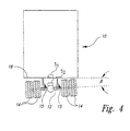
- Figure 4 is a rear view of a semi-tractor-trailer combination illustrating the placement of sensor units with the system of Figure 2A.
- Figure 5A is a rear view of a semi-tractor-trailer combination illustrating an alternative placement of sensor units with the system of Figure 2A.
- Figure 5B is a partial left side view of the semi-tractor-trailer combination of Figure 5A further illustrating the sensor placement and parameters measured by the system of Figure 2A.
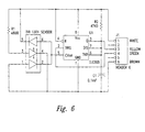
- Figure 6 is a schematic of one embodiment of a sensor unit used with the system of Figure 2A.
- a vehicle 10 such as a semi-tractor-trailer
- COG center of gravity
- the vehicle 10 includes an axle 12, tires 14, suspension system 15, and frame 18 to which various forces are applied.
- the various forces to the axle 12 cancel each other.
- the vehicle 10 in Figure 1B forces are applied to the axle 12 that are uncanceled.
- the vehicle 10 in Figure 1B is illustrated as executing a turn to the right.
- Such a turn causes a lateral acceleration thereby generating a roll moment about a roll axis 16. If the roll moment is sufficiently large, the tires 14 on the right side of the axle 12 lift off the ground and the vehicle 10 rolls over. As those skilled in the art can appreciate, the roll moment is dependent on both the lateral acceleration and the center of gravity. A high center of gravity will cause a greater roll moment than a low center of gravity. A large lateral acceleration causes a greater roll moment than a low lateral acceleration.
- the present invention uses sensors to measure the weight applied to each of the vehicle's drive wheels and to measure lateral acceleration. Based on these measurements, the system calculates the center of gravity of the vehicle and the lateral load transfer between the wheels of the axle 12.
- the present invention is embodied in a system 100, illustrated in the functional block diagram of Figure 2A that provides the vehicle operator with an indication of the height of center of gravity of the vehicle 10 and the lateral load transfer between the wheels of the axle 12.
- the system 100 may also be used as a monitor device to detect potentially dangerous driving habits of the vehicle operator. For example, the system 100 can monitor the lateral acceleration and lateral load transfer and, if the monitored parameters exceed a predetermined threshold, the system 100 can store the parameter values in a memory each time the predetermined threshold is exceeded.
- the memory can retain and display these data values at a later time.
- the system 100 may be installed on a school bus and monitored periodically, such as weekly.
- the memory can display the number of times during the previous week that the lateral acceleration and lateral load transfer exceeded the predetermined threshold. In this manner, potentially dangerous driving habits of the school bus driver may be detected and appropriate measures taken to prevent possible rollover accidents.
- the system 100 includes a central processing unit (CPU) 102, which may be a conventional microprocessor, embedded controller, or the like.
- a memory 104 may include both random access memory (RAM) and read-only memory (ROM).
- a roll moment calculator 105 calculates a roll moment of the vehicle 10.
- a center of gravity calculator 106 calculates a center of gravity of the vehicle 10. In an exemplary embodiment, the functions of roll moment calculator 105 and center of gravity calculator 106 are performed by the CPU 102.
- a display 108 provides the vehicle operator with indications of the center of gravity of the vehicle and of the lateral load transfer.
- the lateral load transfer is displayed as a ratio of the difference in the loads carried by the two sides of the axle 12 to the total axle load.
- a lateral load transfer ratio (LTR) of 1 indicates that the wheels on one side of the axle 12 are lifted off the ground.
- An LTR of -1 indicates that the wheels on the other side of the axle 12 are lifted off the ground.
- FIG. 2B illustrates one embodiment of the display 108.
- the load transfer ratio is displayed on a bar graph 150 having a substantially horizontal orientation to permit easy interpretation by the vehicle operator.
- the center of gravity height is displayed on a bar graph 152 having a substantially vertical orientation to permit easy interpretation by the vehicle operator.
- the display 108 is a color display, the load transfer ratio may be displayed on one color of below a predetermined threshold and displayed with a different color if above the predetermined threshold.
- An alternative embodiment of the display 108 is illustrated in Figure 2C where a conventional gauge, either digital or analog, displays the load transfer ratio.
- the center of gravity height may be displayed as a numeric read out in relative units, or absolute units, such as feet.
- the system 100 may also include an optional audio alarm 109 to provide an audible indication to the vehicle operator when the load transfer ratio exceeds predetermined threshold.
- the system 100 also includes an analog-to-digital converter (ADC) 110 that converts analog input data to digital form for processing by the CPU 102.
- ADC analog-to-digital converter
- the data digitized by the ADC 110 is filtered by a filter 112.
- the filter 112 presently employed by the system 100 is a digital low pass filter with a cut off frequency of 2 Hertz. The low cut off frequency serves to eliminate stray noise and to eliminate the effects of vibrations caused by natural resonances in the suspension system 15, which are typically around 10 Hertz.
- the system 100 also includes a gating circuit 114 and a sample/hold circuit 116 used to display the effective center of gravity.
- the effective center of gravity of the vehicle 10 is calculated based on measured parameters, including the lateral acceleration of the vehicle frame 18 (see Figures 1A and 1B).
- the gating circuit 114 provides an indication to the CPU 102 when the lateral acceleration is above a predetermined threshold.
- the CPU 102 thus calculates the effective center of gravity height only when the gating signal is applied, indicating that the lateral acceleration is above the predetermined threshold.
- the sample and hold circuit 116 uses the currently calculated effective center of gravity when the gating circuit 114 indicates that the lateral acceleration is above the predetermined threshold.
- the sample and hold circuit 116 retains the last calculated value for the effective center of gravity height when the gating circuit 114 indicates that the lateral acceleration is not above the predetermined threshold.
- the sample and hold circuit 116 updates the calculated effective center of gravity height when the lateral acceleration is above the predetermined threshold and stores the last valid calculated center of gravity measurement when the lateral acceleration is not above the predetermined threshold.
- the vehicle operator can manually depress a button (not shown) when the vehicle 10 is undergoing lateral acceleration to activate the gating circuit 114.
- the CPU 102 calculates the effective center of gravity in response to the manual activation of the gating circuit 114 via the button (not shown).
- the sample and hold circuit 116 stores the single value calculated by the CPU for the effective center of gravity height.
- the display 108 is configured to display the current lens and reflects light to the two photodiodes. When the sensor unit is level and the bubble is between the two photodiodes, the sensor produces a level indication. As the sensor unit is rotated, the bubble remains stationary and gradually redirects the light toward one photodiode and away from the other.
- the output of the sensor unit changes proportionately.
- the sensor output is linearly proportional to the amount of incident light.
- the output signal of the sensor unit is fed into the ADC 110 (see Figure 2A) to produce a pulse width modulated waveform which is sent to the CPU 102.
- the CPU 102 measures the width of the pulse and derives the absolute angular position of the sensor unit.
- Using a ratiometric photodiode circuit allows for a low cost ADC 110 that is insensitive to noise, temperature and other environmental factors.
- the sensor units are configured so that they produce a count value that indicates the relative tilt of the sensor. If the sensor unit is tilted so that the side with the cable coming out of it is lower than the opposite side, then the count will decrease indicating a negative angle or movement from the flat "zero" position. If the sensor unit is tilted in the other direction so that the cable side is higher than the opposite side, the count will increase indicating a positive angle or movement from the "zero" position.
- Each sensor unit is contained in a small box with a shielded cable leading to a central junction box (not shown).
- the junction box is then connected to the cab and power system of the vehicle 10.
- the junction box contains a small microprocessor (not shown) which measures each sensor unit in the manner described above and transmits the resulting data to the vehicle's cab for interface to the CPU 102.
- the CPU 102 processes data for both the sensor assembly 122 and the display 108.
- the sensor assembly 122 comprises two or more individual sensor units.
- Figure 6 is a schematic diagram of one sensor unit constructed in accordance with the '771 patent.
- the sensor unit contains an LED and two photodiodes mounted in proximity with the transparent cylindrical container. The output from the photodiodes is used to modulate the input of a TLC555 timer to produce a pulse-width modulated output signal.
- the operation of the TLC555 timer for value for the effective center of gravity height if the gating circuit 114 is active, and display the stored value in the sample and hold circuit 116 if the gating circuit 114 is not active.
- the various components are connected by a bus system 120, which may carry power, status signals, and control signals in addition to data.
- the filter 112, gating circuit 114, and sample and hold circuit 116 may be implemented by appropriate computer instructions stored in the memory 104 and executed by the CPU 102.
- the data storage area that is part of the sample and hold circuit 116 may be a storage register within the CPU 102 or a storage location in the memory 104.
- many components of the system 100 may be implemented by appropriate instructions executed by the CPU 102.
- Figure 2A illustrates these components as independent functional block since each performs a separate task.
- a sensor assembly 122 is used to provide data indicative of the load transfer and lateral acceleration.
- the sensor assembly 122 uses two or more independent sensor units such as the optical tilt sensor units illustrated in U.S. Patent No. 5,218,771 (the '771 patent), which is presently assigned to TV Interactive Data Corporation.
- the sensors described in that patent provide a low cost and rugged detection unit to indicate the orientation of the sensor unit. With one sensor mounted on the frame of the vehicle 10 and another mounted on the suspension, the roll angle of the frame relative to the axle can be determined. Other factors, such as the roll stiffness of the suspension, the truck mass, and the lateral acceleration can be used to calculate the center of gravity of the vehicle 10.
- the roll stiffness of the suspension, and the height of the roll center of the suspension are characteristics that can be estimated and entered into the system 100.
- each sensor unit contains a transparent cylindrical container with a bubble suspended in liquid.
- One end of the cylindrical container contains an infrared LED which illuminates the bubble.
- On both sides of the cylindrical container are photodiodes.
- the bubble acts like a reflective such purposes is well known and need not be described herein.
- the system 100 uses the orientation of two or more individual sensor units to provide an indication of lateral load transfer and lateral acceleration.
- the advantage of the orientation sensing apparatus of the '771 patent is its relatively low cost and ruggedness for operation in the hostile environment of the vehicle suspension system 15 (see Figures 1A and 1B).
- the liquid contained within the sensor units maintains a constant viscosity over the wide operating temperature range encountered by the vehicle 10. Furthermore, each sensor unit is self-contained and sealed, thus eliminating the adverse effects of contaminants such as dirt and water.
- the system 100 may be successfully implemented using a variety of sensors.
- the sensor assembly 122 may be comprised of two or more rotary variable differential transformer (RVDT) sensing units.
- RVDT rotary variable differential transformer
- an RVDT sensing unit generates an electrical signal that varies in response to the rotary position of a sensing element.
- Other types of sensor units useful in the system 100 include a rotary potentiometer, optical encoders, strain gauges, and the like.
- conventional computer input devices may also be used in the sensor assembly 122. For example, it is known in the use of multi-media computers to utilize a glove in which fiber optic cables are attached to fingers of the glove.
- a fiber optic system can be employed by the sensor assembly 122 to determine the tilt angle of the axle 12 and thus provide a measure of the lateral load transfer.
- a conventional accelerometer can provide an indication of lateral acceleration. The present invention is not limited by the specific form of the sensor assembly 122.
- the sensor assembly 122 is typically associated with the drive axle 12 of the vehicle 10. If the vehicle 10 is a tractor-trailer combination, the sensor assembly 122 is generally mounted on one of the drive axles of the tractor. However, multiple trailer combinations, sometimes called a train, are not uncommon on the roadway. With a multiple tractor-trailer combination, research has indicated that rollover accidents tend to begin initially with the axle of the rearmost trailer.
- the sensor assembly 122 may be associated with the axle of the rearmost trailer portion. It is also possible to mount a plurality of sensor assemblies 122 on one or more axles of the vehicle 10.
- the CPU 102 analyzes data from each of the sensor assemblies 122.
- the display 108 is configured to display only the greatest LTR calculated by the CPU 102.
- the basis for the estimation of both the height of the center of gravity and the lateral load transfer ratio is the measurement of the forces transferred between the tires 14 and the road. Direct measurement of these forces would require sensors located between the tires 14 and the road surface. Thus, while the direct measurement of forces is not possible, a free-body analysis of a single axle shows that the forces for that axle between the tires and the road may be inferred from the measurement of the forces and moments between the frame of the vehicle and the axle. From those measurements, the LTR and center of gravity may be calculated. The combination of the LTR and center of gravity can be used by the vehicle operator to determine the sensitivity of the vehicle 10 to a rollover. For example, a high center of gravity may result in vehicle rollover even at low lateral accelerations.
- a rollover occurs when a roll moment, applied to the vehicle through the roll center 16, exceeds the maximum moment which can be applied to the vehicle 10 by the road through the tires 14.
- the applied moment exceeds the maximum moment, the inside wheels of first one axle, then the rest of the axles in turn, lift off of the pavement and a rollover commences.
- Figure 3 illustrates the forces and moments acting upon one axle 12.
- the vectors V , H , and M represent the vertical forces, horizontal forces, and the moment, respectively, applied by the suspension system 15 (see Figures 1A and 1B) onto the axle 12.
- the vectors F l and F r represent the vertical forces applied to tires 14 on the left and right sides of the axle 12, respectively.
- the horizontal contact forces (i.e ., friction) between the tires 14 and the road surface are illustrated in Figure 3, but are not directly related to the present analysis.
- minor forces on the axle 12 itself are indicated by the vectors W and W a .
- the vector W indicates the weight of the axle 12, and the term W a indicates the centrifugal force exerted by the axle where a is the lateral acceleration, measured in "g's.”
- the forces exerted by the suspension on the axle 12 i . e ., V , H , and M ) are taken as acting through the roll center 16 of the suspension.
- the vertical tire forces i.e., F l and F r ) are taken as acting through the center of tire contact patches on each side of the axle 12, a distance T apart.
- Figure 3 illustrates the operation of forces with the assumption that the road surface is horizontal. However, the analysis applies where the road is sloped. In the case of a sloped road, the terms horizontal and vertical are interpreted as being parallel to and perpendicular to the local road slope.
- the center line of the axle 12 will generally be at an angle to the horizontal due to the flexibility of the tires 14 and the different loads carried by each side of the axle.
- Equation (4) defines the difference in tire contact forces.
- the sum of tire contact forces equals the sum of the vertical load V from the frame of the vehicle 10 and the weight W of the axle 12.
- F r + F l V + W where all terms have been previously defined.
- the weight W of the axle 12 is insignificant compared with the typical vertical load V .
- the CPU 102 uses the gating circuit 114 such that the effective height of the center of gravity h cgv is calculated only when the lateral acceleration a is above a predetermined threshold.
- equation (7) approximates the height of the center of gravity.
- Factors such as the rolling of the vehicle frame 18 (see Figures 1A and 1B), may cause a lateral shift that causes the calculated center of gravity to appear higher than the real center of gravity. However, such errors are considered minimal and may be disregarded.
- equation (7) provides a measure of the effective height of the center of gravity, which is a sufficiently close approximation to the real height of the center of gravity.
- the display 108 provides the vehicle operator with an indication of the LTR of the vehicle 10 and the effective center of gravity h cgv of the vehicle.
- equations (6) and (7) above are displayed for the vehicle operator.
- equations (4) and (5) must be solved.
- the height of the roll center h rc 16 of the vehicle 10 and the distance T between the contact patches of the tires 14 are fixed parameters that can be measured for a specific vehicle and will not change. Other parameters, such as the weight W of the axle 12, are fixed parameters, but may be safely ignored.
- variable parameters such as the roll moment M , the horizontal applied force H , and the vertical applied force V are measured by the sensor assembly 122.
- M the roll moment
- k s is a constant indicative of the roll stiffness of the suspension system
- ⁇ is an angle between the axle 12 and frame 18 of the vehicle 10
- C s is a constant indicative of the roll damping of the suspension
- d ⁇ / dt is the rate of change of ⁇ with respect to time.
- the angle ⁇ may be determined in several different manners.
- a first sensor unit S 1 is mounted on the frame 18 of the vehicle 10 while a second sensor unit S 2 is mounted on the axle 12.
- the first and second sensor units S 1 and S 2 provide an indication of the tilt angle of the frame 18 and the tilt angle of the axle 12, respectively.
- the configuration of the sensor assembly unit 122 in Figure 4 is sensitive to vibrations of the axle 12. These vibrations are considered to be noise and thus decrease the signal-to-noise ratio (SNR) of the measurements.
- the sensor assembly 122 (see Figure 2A) comprises the first sensor unit S 1 mounted on the frame 18, a second sensor unit S 2 mounted on a trailing arm 201 on the suspension system 15 of the vehicle 10 on the left side of the axle 12.
- a third sensor unit S 3 is mounted on a trailing arm 20r of the suspension system 15 of the vehicle 10 on the right side of the axle 12.
- the signals from the three sensor units S 1 , S 2 , S 3 are digitized by the ADC 110 (see Figure 2A) and processed by the CPU 102.
- the signals from the second sensor unit S 2 and third sensor unit S 3 are combined to form a differential signal.
- the differential signal generated by the CPU 102 further reduces the noise caused by road vibrations since both the second and third sensor units S 2 and S 3 are exposed to similar road vibrations.
- the differential signal also reduces error caused by other factors, such as road grade or braking of the vehicle 10 in such situations, both sensors S 2 and S 3 measure substantially the same tilt angle caused by the road grade or braking effects and produce a zero differential output signal in response to these external influences.
- the differential signal generated by the sensor units S 2 and S 3 provides a more accurate measure of the angle ⁇ than can be provided with a single sensor unit S 2 mounted directly on the axle 12 (see Figure 4).
- Figure 5B illustrates a side view of the differential sensor mounting and shows the second sensor unit S 2 mounted on the left trailing arm 201.
- the trailing arm 201 is pivotally attached to the frame 18 to define a variable angle ⁇ 1
- the third sensor unit S 3 is similarly mounted on the right trailing arm 20r (see Figure 5A).
- the right trailing arm 20r and the frame 18 define a variable angle ⁇ r .
- the horizontal distance between the pivot point coupling the trailing arms 201 and 20r to the axle 12 is illustrated in Figure 5B by the term e .
- the angle ⁇ between the axle 12 and the frame 18 is less than 10°, and, under normal conditions, is much less than 10°. Under such circumstances, the system 100 uses a linear approximation for the sine functions in equation (9).
- the calculated angle ⁇ and the rate of change of ⁇ with respect to time, d ⁇ / dt may be substituted into equation (8) to determine the roll moment M .
- the constant k s is a measure of suspension stiffness that depends on the geometry of the suspension system 15 (see Figures 1A and 1B). It should be noted that k s may vary slightly if the vehicle 10 uses an air suspension spring. However, such minor variation can be safely ignored.
- the constant C s is a measure of the roll damping of the suspension that depends on the geometry of the suspension system 15.
- the remaining variable parameter measured by the system 100 is the vertical force V exerted by the load of the vehicle 10 including the frame 18 and the load within the vehicle.
- a number of different techniques may be used to determine the vertical force V .
- the vehicle weight can be divided by the number of axles. While such measurements do not take into account the weight of the passengers, this weight is generally small compared to the vehicle weight itself
- vehicles such as tractor-trailer combinations, can measure the vertical force V using truck scales where each pair of axle sets is independently measured to derive the total vehicle weight.
- the measured weight for the axle associated with the sensor assembly 122 (see Figure 2A) is used for the value V .
- a direct measure of the vertical force V can be determined with an air spring suspension system by measuring the air pressure in the spring itself.
- the vertical force V equals the air pressure in the spring times the effective area of the spring. This value may be scaled by a constant indicative of the geometry of the air spring, such as the displacement distance of the air spring from the axle. Thus, a number of techniques may be successfully employed to determine the value for the vertical force V .
- the system 100 can readily calculate the load transfer ratio LTR using equations (4), (5) and (6) and the effective height of the center of gravity using equations (6) and (7).
- the system 100 advantageously provides a low cost and effective technique to provide the vehicle operator with an indication of the likelihood of the vehicle 10 to roll over. The vehicle operator can use this information to operate the vehicle more safely and thus reduce the occurrence of rollover accidents.
Landscapes
- Engineering & Computer Science (AREA)
- Mechanical Engineering (AREA)
- Aviation & Aerospace Engineering (AREA)
- Physics & Mathematics (AREA)
- General Physics & Mathematics (AREA)
- Vehicle Body Suspensions (AREA)
- Air Bags (AREA)
Abstract
Description
- The present invention relates generally to vehicle safety and, more particularly, to a system and method for the detection of conditions leading to vehicle rollover according to the preamble of
claims 1, 29 and 39. - The rollover of vehicles, such as heavy trucks and tractor-trailer combinations, is a serious safety concern. Rollover accidents are the single largest cause to fatalities in the road transport industry and are responsible for most of the bulk spillage of hazardous materials. Heavy trucks and other vehicles are susceptible to rollover accidents because of the high center of gravity relative to the vehicle width. Economic and regulatory conditions are unlikely to change in a manner that would reduce the occurrence of rollover accidents.
- The frequency of rollover accidents may be reduced with technology such as active suspension systems. However, such technologies are expensive. Furthermore, as a practical matter, the weight and power consumption of active suspensions limit their usefulness.
- Another approach to reducing the frequency of rollover accidents is to provide data to drivers to indicate when a rollover accident is likely to occur. However, at highway speeds, a tractor-trailer combination covers its own length in less than a second. For this reason, detection systems alone cannot effectively predict when a rollover accident is about to occur. However, data can be provided to the driver to permit the driver to assess the likelihood of rollover conditions.
- Conventional approaches to this problem are known in the art. For example, the system described in U.S. Patent No. 4,078,224, to Mize, describes a technique where strain gauge sensors are installed on opposing ends of the suspension unit of a vehicle. The opposing strain gauge sensors provide a differential measure of distortion induced by the weight of the vehicle. The differential signal can be quantified to provide an indication of the transverse weight shift of the vehicle from one side to another. However, the transverse weight shift alone does not provide the vehicle operator with sufficient information to determine whether the vehicle is about to roll over.
- Furthermore, this approach requires the installation of strain gauge sensors on the tractor-trailer where the sensors are exposed to the elements and may require frequent replacement. Such an approach is cost prohibitive. The system disclosed in U.S. Patent No. 4,078,224 is particularly effective to indicate that a rollover has commenced. However, it is of minimal value to a driver to confirm that a rollover accident has commenced since the driver can no longer take steps to prevent the rollover accident.
- Another technique, disclosed in U.S. Patent No. 4,722,547, uses ultrasonic transducers on opposite sides of the vehicle. The ultrasonic transducers monitor the distance from the roadway and permit an active suspension system. Again, such techniques are relatively expensive to implement, particularly for a large number of tractor-trailer combinations already on the roads today.
- EP-
A-684 150 describes a system for determining the stability of a vehicle. Pressure sensors are used to measure the pressure or change in pressure on the left-hand and right-hand wheels of the vehicle. Furthermore, a sensor is used to measure the transverse acceleration. Based on these measurements, the resultant force acting on the vehicle is determined using a processor and a simple algorithm. The result is compared to values in a table to determine when the vehicle has reached a critical situation. This critical situation could be indicated to the driver of the vehicle by an audible alarm. Alternatively, a visual display could be used indicating the current condition of the vehicle. Such a display could change its color from green for normal conditions through orange to red for very critical situations. - US-A-4 480 714 describes a system for preventing a carrier from turning sideways. The system derives the dynamic instability of the vehicle during turning based on measured steering angle and running speed of the vehicle in addition to deriving the static stability of the vehicle based on the overall height of the gravitational center. Speed control means disengage a clutch or brake the vehicle if allowable limits are exceeded. In addition, this information can be displayed in a graph showing the relation ship between the steering angle and the running speed allowed in terms of static stability.
- The object of the present invention is to provide a cost effective system and method to detect precisely the presence of rollover conditions to prevent an accident from occurring.
- This object is solved by a system comprising the features of
claims 1 and 29 as well as by a method comprising the steps as recited in claim 39. - A preferred embodiment of this system comprises a sensor assembly coupled to the vehicle to generate the signals indicative of a lateral load transfer of the vehicle and a lateral acceleration of the vehicle. A roll moment calculator coupled to the sensor assembly calculates a roll moment based on the signals from the sensor assembly. A center of gravity calculator, also coupled to the sensor assembly, calculates an effective center of gravity of the vehicle. A roll moment display coupled to the roll moment calculator provides a visual indication of the calculated roll moment. A center of gravity display provides a visual indication of the calculated effective center of gravity of the vehicle to provide an indication of the likelihood of the vehicle to roll over.
- In a preferred embodiment, roll moment calculator and center of gravity calculator are portions of a single processor. The processor calculates a lateral load transfer ratio indicative of an actual roll moment compared to a maximum roll moment, with the display indicating the lateral load transfer ratio.
- In one embodiment, the sensor assembly includes three independent sensor units. The first sensor unit is mounted to the frame to generate signals indicative of lateral acceleration of the vehicle body. The second and third sensor units are oriented to generate signals indicative of lateral load transfer in the suspension system. The second and third sensor units may be mounted on opposing sides of the vehicle axle to generate signals indicative of load transfer from one side of the vehicle axle to the opposing side of the vehicle axle. The second and third sensor units may be processed to generate a differential signal used to determine the lateral load transfer.
- In an alternative embodiment, the sensor assembly comprises two sensor units. The first sensor unit is coupled to the frame to detect lateral acceleration while the second sensor unit is mounted on the vehicle axle. The first and second sensor units are used to detect load transfer from one side of the vehicle axle to the opposing side of the vehicle axle.
- The calculated data may be advantageously displayed as bar graph displays wherein the lateral load transfer is indicated by a bar graph having a substantially horizontal display orientation and the effective center of gravity of the vehicle is displayed on a bar graph having a substantially vertical display orientation. The roll moment display and center of gravity display may be portions of a single display. The display may be a color display unit wherein the lateral load transfer is displayed in a first color when below a predetermined threshold and displayed in a second color when the lateral load transfer is above the predetermined threshold. The system may also include an audio transducer to generate an alert signal when the lateral load transfer is above a predetermined threshold.
- The sensor assembly is typically associated with the drive axle of the vehicle to generate signals indicative of lateral acceleration and lateral load transfer at the drive axle. When the vehicle is a semi-tractor-trailer combination, having at least one drive axle, the sensor assembly is mounted in proximity with the drive axle to generate signals indicative of lateral acceleration and lateral load transfer at the drive axle. When the tractor-trailer combination includes a plurality of trailer portions, each having an axle, the sensor assembly may be mounted in proximity with the axle of at least one of the trailer axles to generate signals indicative of lateral acceleration and lateral load transfer at the trailer axle. The system may also include a plurality of sensor assemblies mounted in proximity with at least two of the plurality of trailer portion axles to generate signals indicative of lateral acceleration and lateral load transfer at the trailer portion axles.
- The system may further include a gating signal applied to the processor wherein the processor calculates the effective center of gravity only when the gating signal is applied. The gating signal may be applied to the processor when the lateral acceleration of the vehicle is above a predetermined threshold. The system may also include a data storage location to store the calculated center of gravity when the gating signal is not applied to the processor. The display indicates the calculated center of gravity when the gating signal is applied and indicates the stored calculated center of gravity when the gating signal is not applied.
- Figure 1A is a rear view of a conventional semi-tractor-trailer combination during normal operation.
- Figure 1B is a rear view of the semi-tractor-trailer combination of Figure 1A when attempting to perform a right-hand turn at an excessive velocity.
- Figure 2A is a functional block diagram of the system of the present invention.
- Figure 2B illustrates one embodiment of the display used by the system of Figure 2A.
- Figure 2C illustrates an alternative embodiment of the display used by the system of Figure 2A.
- Figure 3 is a free-body diagram of a drive axle illustrating parameters measured by the system of Figure 2A.
- Figure 4 is a rear view of a semi-tractor-trailer combination illustrating the placement of sensor units with the system of Figure 2A.
- Figure 5A is a rear view of a semi-tractor-trailer combination illustrating an alternative placement of sensor units with the system of Figure 2A.
- Figure 5B is a partial left side view of the semi-tractor-trailer combination of Figure 5A further illustrating the sensor placement and parameters measured by the system of Figure 2A.
- Figure 6 is a schematic of one embodiment of a sensor unit used with the system of Figure 2A.
- Vehicle rollover accidents commonly occur when the vehicle is attempting to turn at an excessive rate of speed. As illustrated in Figure 1A, a
vehicle 10, such as a semi-tractor-trailer, has a center of gravity (COG), which varies depending on the load carried within thevehicle 10. Thevehicle 10 includes anaxle 12,tires 14,suspension system 15, andframe 18 to which various forces are applied. When thevehicle 10 is moving in a straight line, the various forces to theaxle 12 cancel each other. However, if thevehicle 10 is performing a turn, such as illustrated in Figure 1B, forces are applied to theaxle 12 that are uncanceled. Specifically, thevehicle 10 in Figure 1B is illustrated as executing a turn to the right. Such a turn causes a lateral acceleration thereby generating a roll moment about aroll axis 16. If the roll moment is sufficiently large, thetires 14 on the right side of theaxle 12 lift off the ground and thevehicle 10 rolls over. As those skilled in the art can appreciate, the roll moment is dependent on both the lateral acceleration and the center of gravity. A high center of gravity will cause a greater roll moment than a low center of gravity. A large lateral acceleration causes a greater roll moment than a low lateral acceleration. - To reduce the incidence of rollover accidents, it is necessary to either increase the maximum rollover moment that can be withstood by the
vehicle 10 or to decrease the applied rollover moment. Unfortunately, neither of these quantities can be easily altered. As noted above, there are no known practical solutions to prevent vehicle rollover accidents. Some attempts have been made to provide data to the driver in an effort to warn of an impending vehicle rollover. However, the typical warning system provides only limited information to the driver, and may provide information too late to be of any practical value. - As noted above, the vehicle will roll over when the roll moment is sufficiently large. As is known, an increased center of gravity results in an increased roll moment for a given lateral acceleration. The system of Mize, discussed in the background section, does not provide sufficient data to provide the vehicle operator with an indication of the tendency of the vehicle to roll over.
- The present invention uses sensors to measure the weight applied to each of the vehicle's drive wheels and to measure lateral acceleration. Based on these measurements, the system calculates the center of gravity of the vehicle and the lateral load transfer between the wheels of the
axle 12. The present invention is embodied in asystem 100, illustrated in the functional block diagram of Figure 2A that provides the vehicle operator with an indication of the height of center of gravity of thevehicle 10 and the lateral load transfer between the wheels of theaxle 12. Thesystem 100 may also be used as a monitor device to detect potentially dangerous driving habits of the vehicle operator. For example, thesystem 100 can monitor the lateral acceleration and lateral load transfer and, if the monitored parameters exceed a predetermined threshold, thesystem 100 can store the parameter values in a memory each time the predetermined threshold is exceeded. The memory can retain and display these data values at a later time. For example, thesystem 100 may be installed on a school bus and monitored periodically, such as weekly. The memory can display the number of times during the previous week that the lateral acceleration and lateral load transfer exceeded the predetermined threshold. In this manner, potentially dangerous driving habits of the school bus driver may be detected and appropriate measures taken to prevent possible rollover accidents. - The
system 100 includes a central processing unit (CPU) 102, which may be a conventional microprocessor, embedded controller, or the like. Amemory 104 may include both random access memory (RAM) and read-only memory (ROM). Aroll moment calculator 105 calculates a roll moment of thevehicle 10. A center ofgravity calculator 106 calculates a center of gravity of thevehicle 10. In an exemplary embodiment, the functions ofroll moment calculator 105 and center ofgravity calculator 106 are performed by theCPU 102. - A
display 108 provides the vehicle operator with indications of the center of gravity of the vehicle and of the lateral load transfer. In an exemplary embodiment, the lateral load transfer is displayed as a ratio of the difference in the loads carried by the two sides of theaxle 12 to the total axle load. A lateral load transfer ratio (LTR) of 1 indicates that the wheels on one side of theaxle 12 are lifted off the ground. An LTR of -1 indicates that the wheels on the other side of theaxle 12 are lifted off the ground. - Figure 2B illustrates one embodiment of the
display 108. The load transfer ratio is displayed on abar graph 150 having a substantially horizontal orientation to permit easy interpretation by the vehicle operator. The center of gravity height is displayed on abar graph 152 having a substantially vertical orientation to permit easy interpretation by the vehicle operator. If thedisplay 108 is a color display, the load transfer ratio may be displayed on one color of below a predetermined threshold and displayed with a different color if above the predetermined threshold. An alternative embodiment of thedisplay 108 is illustrated in Figure 2C where a conventional gauge, either digital or analog, displays the load transfer ratio. The center of gravity height may be displayed as a numeric read out in relative units, or absolute units, such as feet. Thesystem 100 may also include anoptional audio alarm 109 to provide an audible indication to the vehicle operator when the load transfer ratio exceeds predetermined threshold. - The
system 100 also includes an analog-to-digital converter (ADC) 110 that converts analog input data to digital form for processing by theCPU 102. The data digitized by theADC 110 is filtered by afilter 112. Thefilter 112 presently employed by thesystem 100 is a digital low pass filter with a cut off frequency of 2 Hertz. The low cut off frequency serves to eliminate stray noise and to eliminate the effects of vibrations caused by natural resonances in thesuspension system 15, which are typically around 10 Hertz. Thesystem 100 also includes agating circuit 114 and a sample/hold circuit 116 used to display the effective center of gravity. As will be discussed in detail below, the effective center of gravity of thevehicle 10 is calculated based on measured parameters, including the lateral acceleration of the vehicle frame 18 (see Figures 1A and 1B). However, when thevehicle 10 is in motion with little or no lateral acceleration, the effective center of gravity will appear to decrease due to the decrease in lateral acceleration. Therefore, thegating circuit 114 provides an indication to theCPU 102 when the lateral acceleration is above a predetermined threshold. TheCPU 102 thus calculates the effective center of gravity height only when the gating signal is applied, indicating that the lateral acceleration is above the predetermined threshold. The sample and holdcircuit 116 uses the currently calculated effective center of gravity when thegating circuit 114 indicates that the lateral acceleration is above the predetermined threshold. However, the sample and holdcircuit 116 retains the last calculated value for the effective center of gravity height when thegating circuit 114 indicates that the lateral acceleration is not above the predetermined threshold. Thus, the sample and holdcircuit 116 updates the calculated effective center of gravity height when the lateral acceleration is above the predetermined threshold and stores the last valid calculated center of gravity measurement when the lateral acceleration is not above the predetermined threshold. - Alternatively, the vehicle operator can manually depress a button (not shown) when the
vehicle 10 is undergoing lateral acceleration to activate thegating circuit 114. In this embodiment, theCPU 102 calculates the effective center of gravity in response to the manual activation of thegating circuit 114 via the button (not shown). The sample and holdcircuit 116 stores the single value calculated by the CPU for the effective center of gravity height. Thedisplay 108 is configured to display the current lens and reflects light to the two photodiodes. When the sensor unit is level and the bubble is between the two photodiodes, the sensor produces a level indication. As the sensor unit is rotated, the bubble remains stationary and gradually redirects the light toward one photodiode and away from the other. As the reflected light changes, the output of the sensor unit changes proportionately. The sensor output is linearly proportional to the amount of incident light. The output signal of the sensor unit is fed into the ADC 110 (see Figure 2A) to produce a pulse width modulated waveform which is sent to theCPU 102. TheCPU 102 measures the width of the pulse and derives the absolute angular position of the sensor unit. Using a ratiometric photodiode circuit allows for alow cost ADC 110 that is insensitive to noise, temperature and other environmental factors. - The sensor units are configured so that they produce a count value that indicates the relative tilt of the sensor. If the sensor unit is tilted so that the side with the cable coming out of it is lower than the opposite side, then the count will decrease indicating a negative angle or movement from the flat "zero" position. If the sensor unit is tilted in the other direction so that the cable side is higher than the opposite side, the count will increase indicating a positive angle or movement from the "zero" position.
- Each sensor unit is contained in a small box with a shielded cable leading to a central junction box (not shown). The junction box is then connected to the cab and power system of the
vehicle 10. In one embodiment, the junction box contains a small microprocessor (not shown) which measures each sensor unit in the manner described above and transmits the resulting data to the vehicle's cab for interface to theCPU 102. In a preferred embodiment, theCPU 102 processes data for both thesensor assembly 122 and thedisplay 108. - As will be discussed in detail below, the
sensor assembly 122 comprises two or more individual sensor units. Figure 6 is a schematic diagram of one sensor unit constructed in accordance with the '771 patent. The sensor unit contains an LED and two photodiodes mounted in proximity with the transparent cylindrical container. The output from the photodiodes is used to modulate the input of a TLC555 timer to produce a pulse-width modulated output signal. The operation of the TLC555 timer for value for the effective center of gravity height if thegating circuit 114 is active, and display the stored value in the sample and holdcircuit 116 if thegating circuit 114 is not active. The various components are connected by abus system 120, which may carry power, status signals, and control signals in addition to data. - It should be noted that many of the components of the
system 100 illustrated in the functional block diagram of Figure 2A are incorporated into theCPU 102. For example, thefilter 112, gatingcircuit 114, and sample and holdcircuit 116 may be implemented by appropriate computer instructions stored in thememory 104 and executed by theCPU 102. Furthermore, the data storage area that is part of the sample and holdcircuit 116 may be a storage register within theCPU 102 or a storage location in thememory 104. Thus, many components of thesystem 100 may be implemented by appropriate instructions executed by theCPU 102. However, Figure 2A illustrates these components as independent functional block since each performs a separate task. - A
sensor assembly 122 is used to provide data indicative of the load transfer and lateral acceleration. In a preferred embodiment, thesensor assembly 122 uses two or more independent sensor units such as the optical tilt sensor units illustrated in U.S. Patent No. 5,218,771 (the '771 patent), which is presently assigned to TV Interactive Data Corporation. The sensors described in that patent provide a low cost and rugged detection unit to indicate the orientation of the sensor unit. With one sensor mounted on the frame of thevehicle 10 and another mounted on the suspension, the roll angle of the frame relative to the axle can be determined. Other factors, such as the roll stiffness of the suspension, the truck mass, and the lateral acceleration can be used to calculate the center of gravity of thevehicle 10. The roll stiffness of the suspension, and the height of the roll center of the suspension are characteristics that can be estimated and entered into thesystem 100. - As described in the '771 patent, each sensor unit contains a transparent cylindrical container with a bubble suspended in liquid. One end of the cylindrical container contains an infrared LED which illuminates the bubble. On both sides of the cylindrical container are photodiodes. When the sensor unit is in the horizontal position, the bubble is centered between the two photodiodes. The bubble acts like a reflective such purposes is well known and need not be described herein. Based on the pulse-width modulation output, it is possible to precisely determine the angular orientation of the bubble within the cylindrical container. The
system 100 uses the orientation of two or more individual sensor units to provide an indication of lateral load transfer and lateral acceleration. - The advantage of the orientation sensing apparatus of the '771 patent is its relatively low cost and ruggedness for operation in the hostile environment of the vehicle suspension system 15 (see Figures 1A and 1B). The liquid contained within the sensor units maintains a constant viscosity over the wide operating temperature range encountered by the
vehicle 10. Furthermore, each sensor unit is self-contained and sealed, thus eliminating the adverse effects of contaminants such as dirt and water. - Although the optical sensing units described in the '771 patent are used in a preferred embodiment, the
system 100 may be successfully implemented using a variety of sensors. For example, thesensor assembly 122 may be comprised of two or more rotary variable differential transformer (RVDT) sensing units. As is known in the art, an RVDT sensing unit generates an electrical signal that varies in response to the rotary position of a sensing element. Other types of sensor units useful in thesystem 100 include a rotary potentiometer, optical encoders, strain gauges, and the like. In addition, conventional computer input devices may also be used in thesensor assembly 122. For example, it is known in the use of multi-media computers to utilize a glove in which fiber optic cables are attached to fingers of the glove. As the user bends the fingers the fiber optic cable is bent, thus increasing the curvature of the cable, resulting in the corresponding decrease in the amount of light transmitted through the fiber optic cable. A fiber optic system can be employed by thesensor assembly 122 to determine the tilt angle of theaxle 12 and thus provide a measure of the lateral load transfer. A conventional accelerometer can provide an indication of lateral acceleration. The present invention is not limited by the specific form of thesensor assembly 122. - Research has indicated that it is possible to recover from a potential vehicle rollover when the tires on one side of a non-drive axle become unloaded and lift off the road surface. In contrast, it has been found that a vehicle rollover becomes unrecoverable when the
tires 14 on one side of the drive axle become unloaded and lift off the road surface. For this reason, thesensor assembly 122 is typically associated with thedrive axle 12 of thevehicle 10. If thevehicle 10 is a tractor-trailer combination, thesensor assembly 122 is generally mounted on one of the drive axles of the tractor. However, multiple trailer combinations, sometimes called a train, are not uncommon on the roadway. With a multiple tractor-trailer combination, research has indicated that rollover accidents tend to begin initially with the axle of the rearmost trailer. With a multiple tractor-trailer combination, thesensor assembly 122 may be associated with the axle of the rearmost trailer portion. It is also possible to mount a plurality ofsensor assemblies 122 on one or more axles of thevehicle 10. In this embodiment, theCPU 102 analyzes data from each of thesensor assemblies 122. Thedisplay 108 is configured to display only the greatest LTR calculated by theCPU 102. - The basis for the estimation of both the height of the center of gravity and the lateral load transfer ratio is the measurement of the forces transferred between the
tires 14 and the road. Direct measurement of these forces would require sensors located between thetires 14 and the road surface. Thus, while the direct measurement of forces is not possible, a free-body analysis of a single axle shows that the forces for that axle between the tires and the road may be inferred from the measurement of the forces and moments between the frame of the vehicle and the axle. From those measurements, the LTR and center of gravity may be calculated. The combination of the LTR and center of gravity can be used by the vehicle operator to determine the sensitivity of thevehicle 10 to a rollover. For example, a high center of gravity may result in vehicle rollover even at low lateral accelerations. - Prior to a detailed discussion of the
system 100, a brief discussion of the physics involved in vehicle rollovers is warranted. As discussed above, a rollover occurs when a roll moment, applied to the vehicle through theroll center 16, exceeds the maximum moment which can be applied to thevehicle 10 by the road through thetires 14. When the applied moment exceeds the maximum moment, the inside wheels of first one axle, then the rest of the axles in turn, lift off of the pavement and a rollover commences. - Figure 3 illustrates the forces and moments acting upon one
axle 12. The vectorsV ,H , andM represent the vertical forces, horizontal forces, and the moment, respectively, applied by the suspension system 15 (see Figures 1A and 1B) onto theaxle 12. The vectorsF l andF r represent the vertical forces applied totires 14 on the left and right sides of theaxle 12, respectively. The horizontal contact forces (i.e., friction) between thetires 14 and the road surface are illustrated in Figure 3, but are not directly related to the present analysis. In addition, minor forces on theaxle 12 itself are indicated by the vectorsW andW a. The vectorW indicates the weight of theaxle 12, and the termW a indicates the centrifugal force exerted by the axle where a is the lateral acceleration, measured in "g's." The forces exerted by the suspension on the axle 12 (i.e.,V ,H , andM ) are taken as acting through theroll center 16 of the suspension. The vertical tire forces (i.e.,F l andF r ) are taken as acting through the center of tire contact patches on each side of theaxle 12, a distance T apart. It should be noted that Figure 3 illustrates the operation of forces with the assumption that the road surface is horizontal. However, the analysis applies where the road is sloped. In the case of a sloped road, the terms horizontal and vertical are interpreted as being parallel to and perpendicular to the local road slope. - The center line of the
axle 12 will generally be at an angle to the horizontal due to the flexibility of thetires 14 and the different loads carried by each side of the axle. Assuming that tire deflection can be modeled as a linear function of the load, the axle angle is related to the vertical tire loads (i.e.,F l andF r ) by the following:F l andF r are the left and right tire forces, respectively, Kt is a measure of stiffness of thetires 14, and T is the distance between the centers of thetires 14 on each side of theaxle 12. It should be noted that equation (1) applies so long as thetires 14 on both sides of theaxle 12 are in contact with the road surface. - The relationship between the moment
M , horizontal forceH , and vertical forceV between theaxle 12 and suspension system 15 (see Figures 1A and 1B) and the distribution of tire loads is given by:T M is the moment,H is the horizontal force caused by turning of thevehicle 10, hrc is the height of theroll center 16,W is the weight of the axle,W a is the centrifugal force exerted by the axle under the influence of lateral acceleration a, and hcga is the height of the center of gravity of theaxle 12. - Equations (1) and (2) may be combined to solve for the difference in forces exerted on the tires (i.e.,
F r -F l ). However, some factors in equations (1) and (2) can be ignored, thus simplifying the calculations performed by the CPU 102 (see Figure 2A). Specifically, the axle angle α is sufficiently small in all practical situations that the tangent of α is approximately zero. Furthermore, the weightW of theaxle 12 is insignificant when compared with the weight of the load in a typical tractor-trailer. Therefore, these terms may be ignored, and equation (2) is simplified as shown below:T - Equation (4) defines the difference in tire contact forces. The sum of tire contact forces equals the sum of the vertical load
V from the frame of thevehicle 10 and the weightW of theaxle 12. This is represented in equation (5) below:W of theaxle 12 is insignificant compared with the typical vertical loadV . Thus, the contribution of the axle weightW in equation (5) can be ignored. The lateral load transfer ratio (LTR) is a function of the left-right tire forces, given by the following: - The height of the center of gravity of the
vehicle 10 can be approximated by the following:vehicle 10, a is the lateral acceleration as measured in "g's", LTR is the lateral load transfer ratio, defined in equation (6) above, and T is the distance between the center of thetires 14 on each side of theaxle 12. As discussed above, the CPU 102 (see Figure 2A) uses thegating circuit 114 such that the effective height of the center of gravity hcgv is calculated only when the lateral acceleration a is above a predetermined threshold. When the lateral acceleration a is below the predetermined threshold, the sample and hold 116 maintains the previous value for the effective height of the center of gravity. The formula in equation (7) above approximates the height of the center of gravity. Factors, such as the rolling of the vehicle frame 18 (see Figures 1A and 1B), may cause a lateral shift that causes the calculated center of gravity to appear higher than the real center of gravity. However, such errors are considered minimal and may be disregarded. Thus, equation (7) provides a measure of the effective height of the center of gravity, which is a sufficiently close approximation to the real height of the center of gravity. - The display 108 (see Figure 2A) provides the vehicle operator with an indication of the LTR of the
vehicle 10 and the effective center of gravity hcgv of the vehicle. Thus, the results of equations (6) and (7) above are displayed for the vehicle operator. To calculate the LTR, equations (4) and (5) must be solved. The height of theroll center h rc 16 of thevehicle 10 and the distance T between the contact patches of thetires 14 are fixed parameters that can be measured for a specific vehicle and will not change. Other parameters, such as the weightW of theaxle 12, are fixed parameters, but may be safely ignored. Finally, variable parameters, such as the roll momentM , the horizontal applied forceH , and the vertical applied forceV are measured by thesensor assembly 122. - The roll moment
M is calculated by the following:M is the roll moment ks is a constant indicative of the roll stiffness of the suspension system, β is an angle between theaxle 12 andframe 18 of thevehicle 10, Cs is a constant indicative of the roll damping of the suspension and dβ / dt is the rate of change of β with respect to time. The angle β may be determined in several different manners. In one embodiment, illustrated in Figure 4, a first sensor unit S1 is mounted on theframe 18 of thevehicle 10 while a second sensor unit S2 is mounted on theaxle 12. The first and second sensor units S1 and S2 provide an indication of the tilt angle of theframe 18 and the tilt angle of theaxle 12, respectively. The difference between the tilt angles measured by the first and second sensor units S1 and S2, respectively, provide a direct measure of the angle β. However, the configuration of thesensor assembly unit 122 in Figure 4 is sensitive to vibrations of theaxle 12. These vibrations are considered to be noise and thus decrease the signal-to-noise ratio (SNR) of the measurements. - In a different configuration of the
sensor assembly 122, illustrated in Figure 5A, the sensor assembly 122 (see Figure 2A) comprises the first sensor unit S1 mounted on theframe 18, a second sensor unit S2 mounted on a trailingarm 201 on thesuspension system 15 of thevehicle 10 on the left side of theaxle 12. A third sensor unit S3 is mounted on a trailingarm 20r of thesuspension system 15 of thevehicle 10 on the right side of theaxle 12. The signals from the three sensor units S1, S2, S3 are digitized by the ADC 110 (see Figure 2A) and processed by theCPU 102. The signals from the second sensor unit S2 and third sensor unit S3 are combined to form a differential signal. Mounting the second and third sensor units S2 and S3 on the trailingarms CPU 102 further reduces the noise caused by road vibrations since both the second and third sensor units S2 and S3 are exposed to similar road vibrations. The differential signal also reduces error caused by other factors, such as road grade or braking of thevehicle 10 in such situations, both sensors S2 and S3 measure substantially the same tilt angle caused by the road grade or braking effects and produce a zero differential output signal in response to these external influences. Thus, the differential signal generated by the sensor units S2 and S3 provides a more accurate measure of the angle β than can be provided with a single sensor unit S2 mounted directly on the axle 12 (see Figure 4). - Figure 5B illustrates a side view of the differential sensor mounting and shows the second sensor unit S2 mounted on the
left trailing arm 201. The trailingarm 201 is pivotally attached to theframe 18 to define a variable angle γ1, the third sensor unit S3 is similarly mounted on theright trailing arm 20r (see Figure 5A). Theright trailing arm 20r and theframe 18 define a variable angle γ r. The horizontal distance between the pivot point coupling the trailingarms axle 12 is illustrated in Figure 5B by the term e. The second and third sensor units S2 and S3 are separated by a distance d (see Figure 5A). It should be noted that the distances d and e are fixed for aparticular vehicle 10. Through the use of well known trigonometric functions, the various angles and distances are interrelated by the following: - The angle β between the
axle 12 and theframe 18 is less than 10°, and, under normal conditions, is much less than 10°. Under such circumstances, thesystem 100 uses a linear approximation for the sine functions in equation (9). The angles β, γl and γr are directly measured and provide a technique for the direct measurement of β, using the following: - The calculated angle β and the rate of change of β with respect to time, dβ / dt, may be substituted into equation (8) to determine the roll moment
M . As previously discussed, the constant ks is a measure of suspension stiffness that depends on the geometry of the suspension system 15 (see Figures 1A and 1B). It should be noted that ks may vary slightly if thevehicle 10 uses an air suspension spring. However, such minor variation can be safely ignored. The constant Cs is a measure of the roll damping of the suspension that depends on the geometry of thesuspension system 15. - The horizontal force
H is defined by the following:frame 18. The tilt angle, defined as δ, is used to define the lateral acceleration a using the following: - The remaining variable parameter measured by the
system 100 is the vertical forceV exerted by the load of thevehicle 10 including theframe 18 and the load within the vehicle. A number of different techniques may be used to determine the vertical forceV . With a vehicle, such as an automobile, van, bus, or the like, the vehicle weight can be divided by the number of axles. While such measurements do not take into account the weight of the passengers, this weight is generally small compared to the vehicle weight itself Alternatively, vehicles such as tractor-trailer combinations, can measure the vertical forceV using truck scales where each pair of axle sets is independently measured to derive the total vehicle weight. The measured weight for the axle associated with the sensor assembly 122 (see Figure 2A) is used for the valueV . A direct measure of the vertical forceV can be determined with an air spring suspension system by measuring the air pressure in the spring itself. The vertical forceV equals the air pressure in the spring times the effective area of the spring. This value may be scaled by a constant indicative of the geometry of the air spring, such as the displacement distance of the air spring from the axle. Thus, a number of techniques may be successfully employed to determine the value for the vertical forceV . - Having described techniques for measuring or calculating constants and variables, the
system 100 can readily calculate the load transfer ratio LTR using equations (4), (5) and (6) and the effective height of the center of gravity using equations (6) and (7). Thus, thesystem 100 advantageously provides a low cost and effective technique to provide the vehicle operator with an indication of the likelihood of thevehicle 10 to roll over. The vehicle operator can use this information to operate the vehicle more safely and thus reduce the occurrence of rollover accidents.
Claims (50)
- A system for the detection of vehicle (10) roll-over conditions, the system comprising:a sensor assembly (S1, S2, S3) coupled to the vehicle (10) and generating at least one signal indicative of a lateral acceleration (a) of the vehicle;a display (108) for indicating the likelihood of the vehicle (10) to roll over; andsaid system being characterized bysaid sensor assembly (S1, S2, S3) further generating at least one signal indicative of a lateral load transfer of the vehicle;a roll moment calculator (105) coupled to said sensor assembly (S1, S2, S3) to calculate a roll moment (M) based on said signals;a center of gravity calculator (106) coupled to said sensor assembly (S1, S2, S3) to calculate an effective center of gravity of the vehicle (10) based on said roll moment and lateral acceleration (a) of the vehicle;said display (108) comprising a roll moment display (150) being coupled to said roll moment calculator (105) to provide a visual display indicative of said roll moment and a center of gravity display (152) to provide a visual display indicative of said effective center of gravity of the vehicle (10) to provide an indication of the likelihood of the vehicle (10) to roll over.
- The system of claim 1 wherein said roll moment calculator (105) calculates a lateral load transfer ratio (LTR) indicative of an actual roll moment compared to a maximum roll moment, said roll moment display (150) indicating said lateral load transfer ratio.
- The system of claim 1 or 2 wherein the vehicle (10) includes a body (18) and a suspension system (15) associated with a vehicle axle (12) and said sensor assembly (S1, S2, S3) comprises first, second and third sensor units, said first sensor unit (S1) being oriented to provide said signals indicative of lateral acceleration of the vehicle body (18), said second and third sensor units (S2, S3) being oriented to provide said signals indicative of lateral load transfer in the suspension system (15).
- The system of claim 3 wherein said first sensor unit (S1) is mounted on the vehicle body (18) to provide said signal indicative of lateral acceleration.
- The system of claim 3 or 4 wherein said second and third sensor units (S2, S3) are mounted on opposing sides of the vehicle axle (12) to provide said signals indicative of lateral load transfer from one side of the vehicle axle (12) to the opposing side of the vehicle axle (12).
- The system of claim 5 wherein said roll moment calculator (105) generates a differential signal from said signals generated by said second and third sensor units (S2, S3) to determine lateral load transfer.
- The system of claim 1 or 2 wherein the vehicle (10) includes a body (18) and a suspension system (15) associated with a vehicle axle (12) and said sensor assembly (S1, S2) comprises first and second sensor units, said first sensor unit (S1) being oriented to provide said signals indicative of lateral acceleration of the vehicle body (18), said second sensor unit (52) being oriented to detect a tilt angle in the suspension system (15).
- The system of claim 7 wherein said first sensor unit (S1) is mounted on the vehicle body (18) to detect lateral acceleration.
- The system of claim 7 wherein said second sensor unit is mounted on the vehicle axle (12) to detect the tilt angle of the vehicle axle (12).
- The system of any of claims 1 to 9 wherein said sensor assembly (S1, S2, S3) comprises at least two optical tilt sensors capable of generating said signals indicative of lateral acceleration and lateral load transfer.
- The system of any of the previous claims wherein said roll moment (150) and center of gravity displays (152) comprise first and second bar graph displays, respectively, said first bar graph display having a substantially horizontal display orientation to indicate lateral load transfer and said second bar graph display having a substantially vertical display orientation to indicate said calculated effective center of gravity of the vehicle.
- The system of any of claims 1 to 10 wherein said roll moment display (150) is a color display and displays lateral load transfer in a first color when lateral load transfer is below a predetermined threshold and displays lateral load transfer in a second color when lateral load transfer is above said predetermined threshold.
- The system of any of the previous claims, further including an audio transducer (109) to generate an alert signal when lateral load transfer is above a predetermined threshold.
- The system of any of the previous claims wherein the vehicle (10) has a drive axle and said sensor assembly (S1, S2, S3) is associated with the drive axle to sense lateral acceleration and lateral load transfer at the drive axle.
- The system of any of the previous claims wherein the vehicle (10) is a tractor-trailer having at least one drive axle, said sensor assembly (S1, S2, S3) being mounted in proximity with the at least one drive axle to provide said signals indicative of lateral acceleration and lateral load transfer at the at least one drive axle.
- The system of any of the previous claims wherein the vehicle (10) is a tractor-trailer having a plurality of trailer portions each having an axle, said sensor assembly (S1, S2, S3) being mounted in proximity with the axle of one of the trailer portion axles to provide said signals indicative of lateral acceleration and lateral load transfer at the trailer portion axle.
- The system of any of the previous claims wherein the vehicle (10) is a tractor-trailer having a plurality of trailer portions each having an axle, the system further including a plurality of sensor assemblies mounted in proximity with at least two of the plurality of trailer portion axles to provide said signals indicative of lateral acceleration and lateral load transfer at the trailer portion axles.
- The system of any of the previous claims wherein the vehicle (10) includes a body (18) and a suspension system (15) associated with a vehicle axle (12) and said roll moment calculator (105) calculates said roll moment by determining an angle formed between the body (18) and the axle.
- The system of claim 18 wherein the vehicle (10) suspension system (15) has a predetermined stiffness and said roll moment calculator (105) calculates said roll moment using said angle formed between the body (18) and the axle and a constant indicative of the predetermined stiffness of the suspension system (15).
- The system of any of the previous claims, further including means for determining a static load applied to the vehicle, said roll moment calculator (105) further calculating a ratio of lateral load transfer and said static load.
- The system of claim 20 wherein said roll moment display (150) provides an indication of said ratio of lateral load transfer and said static load.
- The system of any of the previous claims, further including a gating signal applied to said center of gravity calculator, said center of gravity calculator (106) calculating said effective center of gravity only when said gating signal is applied.
- The system of claim 22 wherein said gating signal applied to said center of gravity calculator (106) when said lateral acceleration is above a predetermined threshold.
- The system of claim 22 or 23, further including a data storage location to store said calculated center of gravity when said gating signal is not applied to said center of gravity calculator, said center of gravity display (152) indicating said calculated center of gravity when said gating signal is applied and indicating said stored said calculated center of gravity when said gating signal is not applied.
- The system of any of the previous claims, further including a data storage location to store a data value for said calculated roll moment if said calculated roll moment exceeds a predetermined threshold.
- The system of claim 25 wherein said data storage location stores a plurality of calculated roll moment values indicative of each time that said calculated roll moment exceeds said predetermined threshold, said roll moment display (150) including a display of each of said plurality of calculated roll moment values.
- The system of any of the previous claims wherein said roll moment calculator (105) and said center of gravity calculator (106) are portions of a single processor.
- The system of claim 27 wherein said roll moment display (150) and said center of gravity display (152) arc portions of a single display.
- A system for the detection of vehicle (10) roll-over conditions, the system comprising:a sensor assembly (S1, S2, S3) coupled to the vehicle (10) and generating at least one signal indicative of a lateral acceleration (a) of the vehicle;a display (108) for indicating the likelihood of the vehicle (10) to roll over; andsaid system being characterized bysaid sensor assembly (S1, S2, S3) further generating at least one signal indicative of a lateral load transfer of the vehicle (10);a center of gravity processor (106) coupled to said sensor assembly (S1, S2, S3) to calculate an effective center of gravity of the vehicle;a lateral load transfer ratio processor coupled to said sensor assembly (S1, S2, S3) to calculate a lateral load transfer ratio (LTR) indicative of an actual lateral load transfer compared to a maximum lateral load transfer;said display comprising a lateral load transfer ratio display (150) coupled to said lateral load transfer ratio processor to provide a visual display indicative of said lateral load transfer ratio and a center of gravity display (152) to provide a visual indication of the effective center of gravity of the vehicle (10) to provide an indication of the likelihood of the vehicle (10) to roll over.
- The system of claim 29 wherein the vehicle (10) includes a body (18) and a suspension system (15) associated with a vehicle axle (12) and said sensor assembly comprises first, second and third sensor units (S1, S2, S3), said first sensor unit (S1) being oriented to provide said signals indicative of lateral acceleration of the vehicle body (18), said second and third sensors units being oriented to provide said signals indicative of lateral load transfer in the suspension system (15).
- The system of claim 30 wherein said first sensor unit (S1) is mounted on the vehicle body (18) to provide said signals indicative of lateral acceleration.
- The system of claim 30 or 31 wherein said second and third sensor units (S2, S3) are mounted on opposing sides of the vehicle axle (12) to provide said signals indicative of load transfer from one side of the vehicle axle (12) to the opposing side of the vehicle axle (12).
- The system of claim 32 wherein said lateral load transfer ratio processor generates a differential signal from said signals generated by said second and third sensor units (S2, S3) to determine said lateral load transfer.
- The system of any of claims 29 to 33, further including a gating signal applied to said lateral load transfer ratio processor, said lateral load transfer ratio processor calculating said effective center of gravity only when said gating signal is applied.
- The system of claim 34 wherein said gating signal applied to said lateral load transfer ratio processor when said lateral acceleration is above a predetermined threshold.
- The system of claim 34 or 35, further including a data storage location to store said calculated center of gravity when said gating signal is not applied to said lateral load transfer ratio processor, said display indicating said calculated center of gravity when said gating signal is applied and indicating said stored said calculated center of gravity when said gating signal is not applied.
- The system of any of claims 29 to 36 wherein said lateral load transfer ratio processor and said center of gravity processor (106) are portions of a single processor.
- The system of any of claims 29 to 37 wherein said lateral load transfer ratio display (150) and said center of gravity display (152) are portions of a single display.
- A method for the detection of vehicle (10) roll-over conditions, the method comprising the steps of:generating a signal indicative a lateral acceleration (a) of the vehicle (10) using a sensor assembly (S1, S2, S3) coupled to the vehicle;displaying data on a display (108) indicative of a roll-over; andprocessing said lateral acceleration signal to obtain values indicative of the likelihood of a vehicle (10) to roll over,said method being characterized by the further steps ofgenerating a signal indicative of a lateral load transfer of the vehicle (10) using said sensor assembly (S1, S2, S3);calculating a roll moment (M) based on said signals indicating the lateral acceleration and said load transfer;calculating an effective center of gravity of the vehicle (10) based on said roll moment and lateral acceleration of the vehicle; anddisplaying data indicative of said calculated roll moment and said calculated effective center of gravity of the vehicle (10) to provide an indication of the likelihood of the vehicle (10) to roll over.
- The method of claim 39 wherein said step of calculating a roll moment calculates a lateral load transfer ratio (LTR) indicative of an actual roll moment compared to a maximum roll moment and said step of displaying data displays data indicating said lateral load transfer ratio.
- The method of claim 39 or 40 wherein the vehicle (10) includes a body (18) and a suspension system (15) associated with a vehicle axle (12) and said sensor assembly (S1, S2, S3) comprises first, second and third sensor units, said first sensor unit (S1) being oriented to provide said signals indicative of lateral acceleration of the vehicle body (18), said second and third sensor units (S2, S3) being oriented to provide said signals indicative of lateral load transfer in the suspension system (15), said step of calculating a roll moment using said signals generated by said first, second and third sensor units.
- The method of claim 41 wherein said first sensor unit (S1) is mounted on the vehicle body (18) to provide said signals indicative of lateral acceleration.
- The method of claim 41 or 42 wherein said second and third sensor units (S2, S3) are mounted on opposing sides of the vehicle axle (12) to provide said signals indicative of load transfer from one side of the vehicle axle (12) to the opposing side of the vehicle axle (12).
- The method of any of claims 41 to 43 wherein said step of calculating said roll moment generates a differential signal from said signals generated by said second and third sensor units (S2, S3) to determine the lateral load transfer.
- The method of claim 39 or 40 wherein the vehicle (10) includes a body (18) and a suspension system (15) associated with a vehicle axle (12) and said sensor assembly (S1, S2, S3) comprises first and second sensor units, said first sensor unit (S1) being oriented to provide said signals indicative of lateral acceleration of the vehicle body (18), said second sensor units being oriented to provide said signals indicative of lateral load transfer in the suspension system (15), said step of calculating a roll moment using said signals generated by said first and second sensor units.
- The method of claim 45 wherein said first sensor unit (S1) is mounted on the vehicle body (18) to provide said signals indicative of lateral acceleration.
- The method of claim 45 or 46 wherein said second sensor unit is mounted on the vehicle axle (12) to provide said signals indicative of load transfer from one side of the vehicle axle (12) to the opposing side of the vehicle axle (12).
- The method of any of claims 39 to 47 wherein said sensor assembly (S1, S2, S3) comprises at least two optical tilt sensors capable of generating said signals indicative of lateral acceleration and lateral load transfer, said step of calculating said roll moment using said signals generated by said optical tilt sensors.
- The method of any of claims 39 to 48, further including the step of storing a data value for said calculated roll moment if said calculated roll moment exceeds a predetermined threshold.
- The method of claim 49 wherein said step of storing stores a plurality of calculated roll moment data values indicative of each time that said calculated roll moment exceeds said predetermined threshold, the method further including the step of displaying each of said plurality of calculated roll moment values.
Applications Claiming Priority (3)
| Application Number | Priority Date | Filing Date | Title |
|---|---|---|---|
| US763006 | 1996-12-10 | ||
| US08/763,006 US5825284A (en) | 1996-12-10 | 1996-12-10 | System and method for the detection of vehicle rollover conditions |
| PCT/US1997/022533 WO1998025779A1 (en) | 1996-12-10 | 1997-12-08 | System and method for the detection of vehicle rollover conditions |
Publications (2)
| Publication Number | Publication Date |
|---|---|
| EP0942839A1 EP0942839A1 (en) | 1999-09-22 |
| EP0942839B1 true EP0942839B1 (en) | 2001-10-04 |
Family
ID=25066641
Family Applications (1)
| Application Number | Title | Priority Date | Filing Date |
|---|---|---|---|
| EP97949791A Expired - Lifetime EP0942839B1 (en) | 1996-12-10 | 1997-12-08 | System and method for the detection of vehicle rollover conditions |
Country Status (9)
| Country | Link |
|---|---|
| US (1) | US5825284A (en) |
| EP (1) | EP0942839B1 (en) |
| JP (1) | JP2001507648A (en) |
| KR (1) | KR20000057486A (en) |
| CN (1) | CN1239919A (en) |
| AT (1) | ATE206368T1 (en) |
| CA (1) | CA2273950A1 (en) |
| DE (1) | DE69707148T2 (en) |
| WO (1) | WO1998025779A1 (en) |
Cited By (1)
| Publication number | Priority date | Publication date | Assignee | Title |
|---|---|---|---|---|
| EP3115263A4 (en) * | 2014-03-05 | 2017-11-01 | National University Corporation Tokyo University of Marine Science And Technology | Rollover danger warning device |
Families Citing this family (245)
| Publication number | Priority date | Publication date | Assignee | Title |
|---|---|---|---|---|
| US8229624B2 (en) * | 1995-06-07 | 2012-07-24 | American Vehicular Sciences Llc | Vehicle diagnostic information generating and transmission systems and methods |
| US8060282B2 (en) * | 1995-06-07 | 2011-11-15 | Automotive Technologies International, Inc. | Vehicle component control methods and systems based on vehicle stability |
| US8157047B2 (en) | 1995-06-07 | 2012-04-17 | Automotive Technologies International, Inc. | Occupant protection systems control techniques |
| US20080046149A1 (en) * | 1995-06-07 | 2008-02-21 | Automotive Technologies International, Inc. | Vehicle Component Control Methods and Systems Based on Vehicle Stability |
| DE19602879C1 (en) * | 1996-01-29 | 1997-08-07 | Knorr Bremse Systeme | Method for detecting the risk of a vehicle tipping over |
| US6202488B1 (en) * | 1996-12-13 | 2001-03-20 | Trw Inc. | Vehicle rollover sensor |
| US6554293B1 (en) * | 1997-12-16 | 2003-04-29 | Continental Teves Ag & Co., Ohg | Method for improving tilt stability in a motor vehicle |
| US6038495A (en) * | 1998-02-06 | 2000-03-14 | Delco Electronics Corporation | Vehicle rollover sensing using short-term integration |
| US6002974A (en) * | 1998-02-06 | 1999-12-14 | Delco Electronics Corporation | Vehicle rollover sensing using extended kalman filter |
| US6002975A (en) * | 1998-02-06 | 1999-12-14 | Delco Electronics Corporation | Vehicle rollover sensing |
| DE19907633A1 (en) * | 1998-04-07 | 1999-10-14 | Bosch Gmbh Robert | Vehicle stabilization procedure, especially for avoiding vehicle tipping over about axis oriented in longitudinal direction |
| DE19823093C2 (en) * | 1998-05-22 | 2000-06-08 | Daimler Chrysler Ag | Device for determining vehicle-specific sizes of a vehicle while driving |
| US6185489B1 (en) * | 1998-06-12 | 2001-02-06 | Roger Dean Strickler | Vehicle overturn monitor |
| DE19828338A1 (en) * | 1998-06-25 | 1999-12-30 | Bosch Gmbh Robert | Determining critical angle of motor vehicle leading to rollover |
| JP2002520605A (en) * | 1998-07-17 | 2002-07-09 | コンティネンタル・テーベス・アクチエンゲゼルシヤフト・ウント・コンパニー・オッフェネ・ハンデルスゲゼルシヤフト | Method and apparatus for determining and detecting danger of vehicle rollover |
| DE19844542A1 (en) * | 1998-09-29 | 2000-03-30 | Bosch Gmbh Robert | Device and method for limiting a rollback speed of a motor vehicle |
| JP3072730B2 (en) * | 1998-10-09 | 2000-08-07 | 日本電気株式会社 | Vehicle detection method and device |
| DE19904908C2 (en) | 1999-02-06 | 2001-03-01 | Daimler Chrysler Ag | Device for determining the distance between vehicle body and vehicle wheel |
| US6397133B1 (en) | 1999-04-19 | 2002-05-28 | Palmer Safety Systems, Llc | Vehicle rollover safety system |
| NL1011873C2 (en) * | 1999-04-23 | 2000-10-24 | Tno | Tilt warning system for vehicles. |
| DE19918597C2 (en) * | 1999-04-23 | 2001-03-08 | Deutsch Zentr Luft & Raumfahrt | Process for reducing the risk of tipping of road vehicles |
| US6301536B1 (en) * | 1999-11-18 | 2001-10-09 | Visteon Global Technologies, Inc. | Method and apparatus for detecting a vehicle rollover |
| DE19958221A1 (en) * | 1999-12-02 | 2001-06-07 | Wabco Gmbh & Co Ohg | Method for preventing a vehicle from tipping over |
| US6262658B1 (en) * | 1999-12-17 | 2001-07-17 | Intel Corporation | Tipping indicator |
| US6332104B1 (en) | 1999-12-21 | 2001-12-18 | Ford Global Technologies, Inc. | Roll over detection for an automotive vehicle |
| US6834218B2 (en) | 2001-11-05 | 2004-12-21 | Ford Global Technologies, Llc | Roll over stability control for an automotive vehicle |
| US6263261B1 (en) | 1999-12-21 | 2001-07-17 | Ford Global Technologies, Inc. | Roll over stability control for an automotive vehicle |
| US6324446B1 (en) | 1999-12-21 | 2001-11-27 | Ford Global Technologies, Inc. | Roll over stability control for an automotive vehicle |
| US6452487B1 (en) * | 2000-02-14 | 2002-09-17 | Stanley Krupinski | System and method for warning of a tip over condition in a tractor trailer or tanker |
| US6417767B1 (en) * | 2000-03-27 | 2002-07-09 | Craig D. Carlson | Device and system for indicating rapid deceleration in vehicles |
| US6507016B1 (en) | 2000-04-18 | 2003-01-14 | Trw Inc. | Apparatus and method for sensing a vehicle rollover condition |
| US6290019B1 (en) | 2000-04-18 | 2001-09-18 | Trw Inc. | System and method for vehicle side rollover aversion |
| US6282474B1 (en) | 2000-06-04 | 2001-08-28 | Ford Global Technologies, Inc. | Method and apparatus for detecting rollover of an automotive vehicle |
| US6327526B1 (en) | 2000-08-02 | 2001-12-04 | Ford Global Technologies, Inc. | Method and apparatus for measuring the rollover resistance and compliance characteristics of a vehicle |
| DE10046036A1 (en) * | 2000-09-18 | 2002-03-28 | Knorr Bremse Systeme | Method for estimating the risk of a vehicle tipping over |
| US6456194B1 (en) | 2000-09-21 | 2002-09-24 | Craig D. Carlson | Device and method for sensing and indicating inclination of an automotive vehicle |
| US6904350B2 (en) | 2000-09-25 | 2005-06-07 | Ford Global Technologies, Llc | System for dynamically determining the wheel grounding and wheel lifting conditions and their applications in roll stability control |
| US7132937B2 (en) | 2000-09-25 | 2006-11-07 | Ford Global Technologies, Llc | Wheel lift identification for an automotive vehicle using passive and active detection |
| US7109856B2 (en) | 2000-09-25 | 2006-09-19 | Ford Global Technologies, Llc | Wheel lifted and grounded identification for an automotive vehicle |
| US6356188B1 (en) * | 2000-09-25 | 2002-03-12 | Ford Global Technologies, Inc. | Wheel lift identification for an automotive vehicle |
| US7233236B2 (en) | 2000-09-25 | 2007-06-19 | Ford Global Technologies, Llc | Passive wheel lift identification for an automotive vehicle using operating input torque to wheel |
| US6397127B1 (en) * | 2000-09-25 | 2002-05-28 | Ford Global Technologies, Inc. | Steering actuated wheel lift identification for an automotive vehicle |
| US6495820B1 (en) | 2000-10-02 | 2002-12-17 | Trw Inc. | Sensor apparatus and method for sensing angular rotation of an object using light reflected off a rotor and bifurcation compensation |
| US6498976B1 (en) * | 2000-10-30 | 2002-12-24 | Freightliner Llc | Vehicle operator advisor system and method |
| US6584388B2 (en) | 2001-11-08 | 2003-06-24 | Delphi Technologies, Inc. | Adaptive rollover detection apparatus and method |
| US6542792B2 (en) | 2000-11-29 | 2003-04-01 | Delphi Technologies, Inc. | Vehicle rollover detection apparatus and method |
| US6437701B1 (en) * | 2000-12-18 | 2002-08-20 | Caterpillar Inc. | Apparatus and method for a machine stability system for an articulated work machine |
| US6542073B2 (en) | 2000-12-20 | 2003-04-01 | Trw Inc. | System and method for sensing vehicle rollover |
| US6433681B1 (en) * | 2000-12-20 | 2002-08-13 | Trw Inc. | Apparatus and method for detecting vehicle rollover having roll-rate switched threshold |
| US6600414B2 (en) * | 2000-12-20 | 2003-07-29 | Trw Inc. | Apparatus and method for detecting vehicle rollover having a discriminating safing function |
| JP3788286B2 (en) * | 2001-01-19 | 2006-06-21 | トヨタ自動車株式会社 | Control device for occupant protection device |
| US6799092B2 (en) | 2001-02-21 | 2004-09-28 | Ford Global Technologies, Llc | Rollover stability control for an automotive vehicle using rear wheel steering and brake control |
| EP1236620B1 (en) | 2001-03-01 | 2007-01-24 | Automotive Systems Laboratory Inc. | Vehicle rollover detection system |
| US6535800B2 (en) | 2001-05-29 | 2003-03-18 | Delphi Technologies, Inc. | Vehicle rollover sensing using angular rate sensors |
| DE10130407A1 (en) * | 2001-06-23 | 2003-01-02 | Daimler Chrysler Ag | Method for avoiding rollover on semi-trailers |
| US6985795B2 (en) | 2001-09-21 | 2006-01-10 | Schlage Lock Company | Material handler with center of gravity monitoring system |
| US6654674B2 (en) | 2001-11-21 | 2003-11-25 | Ford Global Technologies, Llc | Enhanced system for yaw stability control system to include roll stability control function |
| KR100418680B1 (en) * | 2001-11-23 | 2004-02-11 | 기아자동차주식회사 | Apparatus and Method for Alarming Danger When a Car is Cornering Down in a Slope |
| DE10161799A1 (en) * | 2001-12-15 | 2003-06-26 | Man Nutzfahrzeuge Ag | Procedure for determining the effective overturning moment and / or the current center of gravity of a vehicle on board |
| US6654671B2 (en) | 2002-02-15 | 2003-11-25 | Delphi Technologies, Inc. | Vehicle rollover detection having variable sensitivity |
| US6556908B1 (en) | 2002-03-04 | 2003-04-29 | Ford Global Technologies, Inc. | Attitude sensing system for an automotive vehicle relative to the road |
| US6938716B1 (en) | 2002-03-18 | 2005-09-06 | Schwing America, Inc. | Concrete mixing truck anti-rollover system |
| US7057503B2 (en) * | 2002-03-19 | 2006-06-06 | Automotive Systems Laboratory, Inc. | Vehicle rollover detection system |
| JP4317032B2 (en) * | 2002-03-19 | 2009-08-19 | オートモーティブ システムズ ラボラトリー インコーポレーテッド | Vehicle rollover detection system |
| US20060267296A1 (en) * | 2002-04-23 | 2006-11-30 | Dodd C I | Electronic control of vehicle air suspension |
| US6918600B2 (en) * | 2002-04-23 | 2005-07-19 | Barksdale, Inc. | Electronic control of vehicle air suspension |
| US6741922B2 (en) * | 2002-05-30 | 2004-05-25 | Bendix Commercial Vehicle Systems Llc | Antilock braking system based roll over prevention |
| US7194351B2 (en) | 2002-08-01 | 2007-03-20 | Ford Global Technologies, Llc | System and method for determining a wheel departure angle for a rollover control system |
| US7079928B2 (en) | 2002-08-01 | 2006-07-18 | Ford Global Technologies, Llc | System and method for determining a wheel departure angle for a rollover control system with respect to road roll rate and loading misalignment |
| US7085639B2 (en) | 2002-08-01 | 2006-08-01 | Ford Global Technologies, Llc | System and method for characterizing the road bank for vehicle roll stability control |
| US6941205B2 (en) | 2002-08-01 | 2005-09-06 | Ford Global Technologies, Llc. | System and method for deteching roll rate sensor fault |
| US7302331B2 (en) | 2002-08-01 | 2007-11-27 | Ford Global Technologies, Inc. | Wheel lift identification for an automotive vehicle |
| US7003389B2 (en) | 2002-08-01 | 2006-02-21 | Ford Global Technologies, Llc | System and method for characterizing vehicle body to road angle for vehicle roll stability control |
| US6963797B2 (en) | 2002-08-05 | 2005-11-08 | Ford Global Technologies, Llc | System and method for determining an amount of control for operating a rollover control system |
| US7085642B2 (en) | 2002-08-05 | 2006-08-01 | Ford Global Technologies, Llc | Method and system for correcting sensor offsets |
| US6961648B2 (en) | 2002-08-05 | 2005-11-01 | Ford Motor Company | System and method for desensitizing the activation criteria of a rollover control system |
| US7430468B2 (en) | 2002-08-05 | 2008-09-30 | Ford Global Technologies, Llc | System and method for sensitizing the activation criteria of a rollover control system |
| DE10239406A1 (en) * | 2002-08-28 | 2004-03-11 | Robert Bosch Gmbh | Vehicle rollover detection device |
| DE10247993B4 (en) * | 2002-10-15 | 2011-02-17 | Robert Bosch Gmbh | Method and device for determining the center of gravity of a motor vehicle |
| US20040133365A1 (en) * | 2002-11-05 | 2004-07-08 | Drumm Stefan A. | Method of determining forces and torques acting on a riding vehicle |
| SE525248C2 (en) * | 2003-02-18 | 2005-01-11 | Scania Cv Ab | Arrangement and method for estimating the center of gravity of a vehicle |
| US9162656B2 (en) | 2003-02-26 | 2015-10-20 | Ford Global Technologies, Llc | Active driven wheel lift identification for an automotive vehicle |
| US7653471B2 (en) | 2003-02-26 | 2010-01-26 | Ford Global Technologies, Llc | Active driven wheel lift identification for an automotive vehicle |
| DE10319443A1 (en) * | 2003-04-30 | 2004-11-18 | Robert Bosch Gmbh | Device for controlling restraint devices |
| US7136731B2 (en) | 2003-06-11 | 2006-11-14 | Ford Global Technologies, Llc | System for determining vehicular relative roll angle during a potential rollover event |
| JP4145741B2 (en) * | 2003-07-03 | 2008-09-03 | 三菱電機株式会社 | Vehicle rollover discrimination device and vehicle rollover discrimination method |
| WO2005007426A1 (en) * | 2003-07-11 | 2005-01-27 | Robert Bosch Gmbh | Driving dynamics regulation system adapted to the rolling behaviour of a vehicle |
| US20050033549A1 (en) * | 2003-07-25 | 2005-02-10 | Siemens Vdo Automotive Corporation | Rollover sensing using tire pressure sensor |
| US20050036560A1 (en) * | 2003-08-14 | 2005-02-17 | Adc Dsl Systems, Inc. | Cable calculator |
| DE10338879A1 (en) * | 2003-08-23 | 2005-03-17 | Wabco Gmbh & Co.Ohg | Method for estimating a lateral acceleration of a vehicle |
| US7145442B1 (en) * | 2003-10-14 | 2006-12-05 | Yu Hei Sunny Wai | Vehicle operation display system |
| DE102004006696A1 (en) * | 2003-10-24 | 2005-06-02 | Robert Bosch Gmbh | Method for roll-over stabilizing of vehicle in critical driving conditions entails determining mass of vehicle and putting into effect roll-over stabilizing algorithm in dependence upon this mass |
| CN100554016C (en) * | 2003-10-24 | 2009-10-28 | 罗伯特.博世有限公司 | The driving dynamics control system that is complementary with the vehicle loading situation |
| US6983583B2 (en) * | 2003-11-21 | 2006-01-10 | Ariens Company | Lawnmower tilt sensor apparatus and method |
| US7512461B2 (en) * | 2003-11-25 | 2009-03-31 | Delphi Technologies, Inc. | Vehicle rollover sensing using angular accelerometer |
| JP2005178420A (en) * | 2003-12-16 | 2005-07-07 | Honda Motor Co Ltd | Saddle riding type vehicle for traveling on irregular ground |
| US7162340B2 (en) * | 2004-01-08 | 2007-01-09 | Delphi Technologies, Inc. | Vehicle rollover detection and method of anticipating vehicle rollover |
| DE102004003718A1 (en) * | 2004-01-24 | 2005-08-11 | Conti Temic Microelectronic Gmbh | Method and device for triggering an occupant protection system |
| US7502675B2 (en) | 2004-04-01 | 2009-03-10 | Delphi Technologies, Inc. | Feedforward control of motor vehicle roll angle |
| US7308350B2 (en) | 2004-05-20 | 2007-12-11 | Ford Global Technologies, Llc | Method and apparatus for determining adaptive brake gain parameters for use in a safety system of an automotive vehicle |
| US7403848B2 (en) * | 2004-08-16 | 2008-07-22 | Delphi Technologies, Inc. | Vehicle rollover detection method |
| US7191047B2 (en) | 2004-09-27 | 2007-03-13 | Delphi Technologies, Inc. | Motor vehicle control using a dynamic feedforward approach |
| US7715965B2 (en) | 2004-10-15 | 2010-05-11 | Ford Global Technologies | System and method for qualitatively determining vehicle loading conditions |
| US7668645B2 (en) | 2004-10-15 | 2010-02-23 | Ford Global Technologies | System and method for dynamically determining vehicle loading and vertical loading distance for use in a vehicle dynamic control system |
| US7239952B2 (en) * | 2004-12-08 | 2007-07-03 | Continental Teves, Inc. | Reduced order parameter identification for vehicle rollover control system |
| US7660654B2 (en) | 2004-12-13 | 2010-02-09 | Ford Global Technologies, Llc | System for dynamically determining vehicle rear/trunk loading for use in a vehicle control system |
| US7557697B2 (en) * | 2005-02-22 | 2009-07-07 | Continental Teves, Inc. | System to measure wheel liftoff |
| FR2884311A1 (en) * | 2005-04-12 | 2006-10-13 | Renault Sas | Road`s slope and superelevation estimation, for motor vehicle, involves determining slope and superelevation based on vertical forces, vertical and lateral acceleration components and weight and center of gravity`s position of vehicle |
| DE102005021721A1 (en) * | 2005-05-11 | 2006-11-16 | Zf Friedrichshafen Ag | Method for controlling driving functions of a vehicle |
| US20070017715A1 (en) * | 2005-07-20 | 2007-01-25 | Mccann Gerard O | Bogie slider control system and method utilizing trailer weight information |
| US7477972B2 (en) * | 2005-08-01 | 2009-01-13 | Delphi Technologies, Inc. | Rollover warning and detection method for transport vehicles |
| US7590481B2 (en) | 2005-09-19 | 2009-09-15 | Ford Global Technologies, Llc | Integrated vehicle control system using dynamically determined vehicle conditions |
| US7600826B2 (en) | 2005-11-09 | 2009-10-13 | Ford Global Technologies, Llc | System for dynamically determining axle loadings of a moving vehicle using integrated sensing system and its application in vehicle dynamics controls |
| US8121758B2 (en) | 2005-11-09 | 2012-02-21 | Ford Global Technologies | System for determining torque and tire forces using integrated sensing system |
| WO2007065077A2 (en) * | 2005-12-02 | 2007-06-07 | Gm Global Technology Operations, Inc. | In-vehicle determination of the relative center of gravity height |
| US10878646B2 (en) | 2005-12-08 | 2020-12-29 | Smartdrive Systems, Inc. | Vehicle event recorder systems |
| US20070150138A1 (en) | 2005-12-08 | 2007-06-28 | James Plante | Memory management in event recording systems |
| US8359146B2 (en) * | 2005-12-15 | 2013-01-22 | Bendix Commercial Vehicle Systems Llc | Single channel roll stability system |
| JP4811089B2 (en) * | 2006-02-02 | 2011-11-09 | いすゞ自動車株式会社 | Vehicle rollover risk determination device |
| WO2007098891A1 (en) * | 2006-03-03 | 2007-09-07 | National University Of Ireland Maynooth | Method for determining the centre of gravity for an automotive vehicle |
| US8996240B2 (en) | 2006-03-16 | 2015-03-31 | Smartdrive Systems, Inc. | Vehicle event recorders with integrated web server |
| US9201842B2 (en) | 2006-03-16 | 2015-12-01 | Smartdrive Systems, Inc. | Vehicle event recorder systems and networks having integrated cellular wireless communications systems |
| US7571030B2 (en) * | 2006-04-10 | 2009-08-04 | Gm Global Technology Operations, Inc. | Estimation of vehicle roll rate and roll angle using suspension deflection sensors |
| US7873454B2 (en) * | 2006-05-03 | 2011-01-18 | Eaton Corporation | Method of identifying predictive lateral load transfer ratio for vehicle rollover prevention and warning systems |
| US8269617B2 (en) * | 2009-01-26 | 2012-09-18 | Drivecam, Inc. | Method and system for tuning the effect of vehicle characteristics on risk prediction |
| US8849501B2 (en) * | 2009-01-26 | 2014-09-30 | Lytx, Inc. | Driver risk assessment system and method employing selectively automatic event scoring |
| US8508353B2 (en) * | 2009-01-26 | 2013-08-13 | Drivecam, Inc. | Driver risk assessment system and method having calibrating automatic event scoring |
| US9067565B2 (en) | 2006-05-22 | 2015-06-30 | Inthinc Technology Solutions, Inc. | System and method for evaluating driver behavior |
| US8630768B2 (en) | 2006-05-22 | 2014-01-14 | Inthinc Technology Solutions, Inc. | System and method for monitoring vehicle parameters and driver behavior |
| US7805231B2 (en) * | 2006-06-29 | 2010-09-28 | Delphi Technologies, Inc. | Integrated vehicle crash sensing system and method |
| DE102006045303B3 (en) * | 2006-09-26 | 2008-02-07 | Siemens Ag | Vehicle`s absolute inclination angle recognition method, involves determining absolute inclination angle of vehicle based on acceleration, temporal conduction of speed and yaw rate, which is determined by using yaw rate sensor |
| DE102006045304A1 (en) * | 2006-09-26 | 2008-04-03 | Siemens Ag | Method and apparatus for estimating the center of gravity of a vehicle |
| US7899610B2 (en) | 2006-10-02 | 2011-03-01 | Inthinc Technology Solutions, Inc. | System and method for reconfiguring an electronic control unit of a motor vehicle to optimize fuel economy |
| US8989959B2 (en) | 2006-11-07 | 2015-03-24 | Smartdrive Systems, Inc. | Vehicle operator performance history recording, scoring and reporting systems |
| US8649933B2 (en) | 2006-11-07 | 2014-02-11 | Smartdrive Systems Inc. | Power management systems for automotive video event recorders |
| US8868288B2 (en) | 2006-11-09 | 2014-10-21 | Smartdrive Systems, Inc. | Vehicle exception event management systems |
| US8483942B2 (en) | 2006-11-22 | 2013-07-09 | National University Corporatioin Tokyo University of Marine Science and Technology | System for detecting or estimating center-of-gravity, lateral rollover limit or cargo weight |
| GB0623802D0 (en) | 2006-11-29 | 2007-01-10 | Brown Duncan | An arrangement of interconnected devices or system to indicate loading state or overload of the axles on a vehicle |
| WO2008103659A1 (en) * | 2007-02-19 | 2008-08-28 | Solidica, Inc. | Vehicle rollover detection and prevention system |
| US8019514B2 (en) * | 2007-02-28 | 2011-09-13 | Caterpillar Inc. | Automated rollover prevention system |
| GB2448691B (en) * | 2007-04-23 | 2010-03-10 | Knorr Bremse Systeme | Tilt Angle Sensor for Stability Control of a Vehicle |
| US7573375B2 (en) * | 2007-05-02 | 2009-08-11 | Paccar Inc | Rollover prediction and warning method |
| US8239092B2 (en) | 2007-05-08 | 2012-08-07 | Smartdrive Systems Inc. | Distributed vehicle event recorder systems having a portable memory data transfer system |
| US8825277B2 (en) | 2007-06-05 | 2014-09-02 | Inthinc Technology Solutions, Inc. | System and method for the collection, correlation and use of vehicle collision data |
| US7922196B2 (en) * | 2007-06-11 | 2011-04-12 | Ford Global Technologies, Llc | Sensor integration for airbag deployment |
| US8666590B2 (en) | 2007-06-22 | 2014-03-04 | Inthinc Technology Solutions, Inc. | System and method for naming, filtering, and recall of remotely monitored event data |
| US9129460B2 (en) | 2007-06-25 | 2015-09-08 | Inthinc Technology Solutions, Inc. | System and method for monitoring and improving driver behavior |
| US7999670B2 (en) | 2007-07-02 | 2011-08-16 | Inthinc Technology Solutions, Inc. | System and method for defining areas of interest and modifying asset monitoring in relation thereto |
| US9117246B2 (en) | 2007-07-17 | 2015-08-25 | Inthinc Technology Solutions, Inc. | System and method for providing a user interface for vehicle mentoring system users and insurers |
| US8818618B2 (en) | 2007-07-17 | 2014-08-26 | Inthinc Technology Solutions, Inc. | System and method for providing a user interface for vehicle monitoring system users and insurers |
| US8577703B2 (en) | 2007-07-17 | 2013-11-05 | Inthinc Technology Solutions, Inc. | System and method for categorizing driving behavior using driver mentoring and/or monitoring equipment to determine an underwriting risk |
| US7876205B2 (en) | 2007-10-02 | 2011-01-25 | Inthinc Technology Solutions, Inc. | System and method for detecting use of a wireless device in a moving vehicle |
| DE102007051218A1 (en) * | 2007-10-26 | 2009-04-30 | Volkswagen Ag | Method and control system / control component for determining dynamic pitch, roll and / or lifting axes |
| GB2454223B (en) * | 2007-11-01 | 2011-09-21 | Haldex Brake Products Ltd | Vehicle stability control method |
| EP2072294A1 (en) * | 2007-12-18 | 2009-06-24 | Iveco S.p.A. | Method and system for detecting the load of a vehicle equipped with non-pneumatic suspensions |
| US8019511B2 (en) | 2008-05-22 | 2011-09-13 | Ford Global Technologies, Llc | Vehicle rollover detection |
| US8688180B2 (en) | 2008-08-06 | 2014-04-01 | Inthinc Technology Solutions, Inc. | System and method for detecting use of a wireless device while driving |
| DE102008049174B4 (en) * | 2008-09-26 | 2013-11-14 | Staude & Company | Method for controlling the Electronic Stability Program (ESP) of vehicle trailers |
| US8854199B2 (en) | 2009-01-26 | 2014-10-07 | Lytx, Inc. | Driver risk assessment system and method employing automated driver log |
| US8963702B2 (en) | 2009-02-13 | 2015-02-24 | Inthinc Technology Solutions, Inc. | System and method for viewing and correcting data in a street mapping database |
| US8188887B2 (en) | 2009-02-13 | 2012-05-29 | Inthinc Technology Solutions, Inc. | System and method for alerting drivers to road conditions |
| US8892341B2 (en) | 2009-02-13 | 2014-11-18 | Inthinc Technology Solutions, Inc. | Driver mentoring to improve vehicle operation |
| WO2010117762A2 (en) | 2009-03-30 | 2010-10-14 | Lord Corporation | Land vehicles and systems with controllable suspension systems |
| WO2011004459A1 (en) * | 2009-07-07 | 2011-01-13 | トヨタ自動車株式会社 | Vehicle control system, and operation device |
| JP5279678B2 (en) * | 2009-10-19 | 2013-09-04 | 本田技研工業株式会社 | Portable work machine |
| US20130060423A1 (en) * | 2010-05-14 | 2013-03-07 | Lord Corporation | Land vehicles and systems with controllable suspension systems |
| US9541389B2 (en) * | 2010-05-21 | 2017-01-10 | National University Corporation Tokyo University Of Marine Science And Technology | Center-of-gravity detecting system |
| CN101967883B (en) * | 2010-09-09 | 2012-02-22 | 安徽星马汽车股份有限公司 | Overturn prevention control circuit for pumper |
| CN102756686B (en) * | 2011-04-26 | 2015-07-29 | 贵州大学 | The method and apparatus of early warning vehicle rollover |
| JP5709655B2 (en) * | 2011-06-07 | 2015-04-30 | 日野自動車株式会社 | Display device, vehicle, display method, and program |
| DE102011111862A1 (en) * | 2011-08-31 | 2013-02-28 | Wabco Gmbh | A method of warning the driver of a vehicle of an impending tipping and control device therefor |
| US8606492B1 (en) | 2011-08-31 | 2013-12-10 | Drivecam, Inc. | Driver log generation |
| US8744642B2 (en) | 2011-09-16 | 2014-06-03 | Lytx, Inc. | Driver identification based on face data |
| US8996234B1 (en) | 2011-10-11 | 2015-03-31 | Lytx, Inc. | Driver performance determination based on geolocation |
| US9298575B2 (en) | 2011-10-12 | 2016-03-29 | Lytx, Inc. | Drive event capturing based on geolocation |
| GB2497134B8 (en) | 2011-12-02 | 2014-07-23 | Caterpiller Sarl | Determing the relative orientation of members of an articulated work machine |
| US8989914B1 (en) | 2011-12-19 | 2015-03-24 | Lytx, Inc. | Driver identification based on driving maneuver signature |
| CN102529960B (en) * | 2012-02-15 | 2015-04-15 | 三一汽车制造有限公司 | Control method and control system for preventing side overturn and mixing transport vehicle |
| US9240079B2 (en) | 2012-04-17 | 2016-01-19 | Lytx, Inc. | Triggering a specialized data collection mode |
| US8676428B2 (en) | 2012-04-17 | 2014-03-18 | Lytx, Inc. | Server request for downloaded information from a vehicle-based monitor |
| CN103419589A (en) * | 2012-05-24 | 2013-12-04 | 昆达电脑科技(昆山)有限公司 | Vehicle sideslip angle sensing device |
| US9728228B2 (en) | 2012-08-10 | 2017-08-08 | Smartdrive Systems, Inc. | Vehicle event playback apparatus and methods |
| WO2014028594A2 (en) * | 2012-08-14 | 2014-02-20 | The Trustees Of Columbia University In The City Of New York | Imaging interfaces for full finger and full hand optical tomography |
| CN102901550B (en) * | 2012-11-15 | 2014-08-13 | 陕西电器研究所 | Method for implementing vehicle-mounted dynamic weighing |
| KR101410647B1 (en) * | 2012-11-28 | 2014-06-24 | 현대자동차주식회사 | Vehicle rollover prevention system |
| US9344683B1 (en) | 2012-11-28 | 2016-05-17 | Lytx, Inc. | Capturing driving risk based on vehicle state and automatic detection of a state of a location |
| DE102014201668B4 (en) | 2013-03-07 | 2021-09-02 | Ford Global Technologies, Llc | Laterally tiltable, multi-lane vehicle |
| DE102014201632B4 (en) | 2013-03-07 | 2021-09-02 | Ford Global Technologies, Llc | Laterally tiltable, multi-lane vehicle |
| DE102014201670A1 (en) | 2013-03-07 | 2014-09-11 | Ford Global Technologies, Llc | Sideways inclinable, multi-lane vehicle |
| DE102014201127B4 (en) | 2013-03-07 | 2022-02-03 | Ford Global Technologies, Llc | Side-tilting, multi-track vehicle |
| DE102014201630B4 (en) | 2013-03-07 | 2021-09-02 | Ford Global Technologies, Llc | Laterally tiltable, multi-lane vehicle |
| FR3003834B1 (en) * | 2013-03-26 | 2015-04-24 | Univ Blaise Pascal Clermont Ii | METHOD OF REDUCING THE RISK OF TILTING OF A MOTOR VEHICLE EQUIPPED WITH A PILOTABLE SUSPENSION SYSTEM |
| CN103213582B (en) * | 2013-04-18 | 2016-08-24 | 上海理工大学 | Anti-rollover pre-warning and control method based on body roll angular estimation |
| US8990000B2 (en) | 2013-04-23 | 2015-03-24 | Ford Global Technologies, Llc | Active suspension with load detection and adaptation |
| DE102013014819A1 (en) * | 2013-09-10 | 2015-03-12 | Wabco Gmbh | Method for stabilizing the driveability of a vehicle combination and driving dynamics control device |
| US9501878B2 (en) | 2013-10-16 | 2016-11-22 | Smartdrive Systems, Inc. | Vehicle event playback apparatus and methods |
| US9172477B2 (en) | 2013-10-30 | 2015-10-27 | Inthinc Technology Solutions, Inc. | Wireless device detection using multiple antennas separated by an RF shield |
| US9610955B2 (en) | 2013-11-11 | 2017-04-04 | Smartdrive Systems, Inc. | Vehicle fuel consumption monitor and feedback systems |
| US9128113B2 (en) | 2014-01-27 | 2015-09-08 | Nissan North America, Inc. | Vehicle orientation indicator |
| GB2523185B (en) | 2014-02-18 | 2017-03-08 | Caterpillar Sarl | Method of determining whether a frame of a work machine is approaching a tip over point |
| US8892310B1 (en) | 2014-02-21 | 2014-11-18 | Smartdrive Systems, Inc. | System and method to detect execution of driving maneuvers |
| US9283825B2 (en) | 2014-02-25 | 2016-03-15 | Isam Mousa | System, method, and apparatus to prevent commercial vehicle rollover |
| US9862341B2 (en) * | 2014-06-09 | 2018-01-09 | Nitin Govind RAM | Two-wheeler airbag system |
| CN104006974B (en) * | 2014-06-12 | 2016-03-30 | 四川省农业机械研究设计院 | Hand-held rural area Work machine was climbed ridge characteristic performance pick-up unit |
| KR101568147B1 (en) * | 2014-08-29 | 2016-07-20 | (주)지니정보통신 | System for monitoring state of car and method for processing thereof |
| DE102014217246B3 (en) | 2014-08-29 | 2015-12-24 | Ford Global Technologies, Llc | Stabilization arrangement for a tilting chassis of a vehicle |
| DE102014217386A1 (en) | 2014-09-01 | 2016-03-03 | Ford Global Technologies, Llc | Method for operating a tilting chassis and active tilting suspension for a rail-bound vehicle |
| US9663127B2 (en) | 2014-10-28 | 2017-05-30 | Smartdrive Systems, Inc. | Rail vehicle event detection and recording system |
| US9914392B2 (en) * | 2014-10-30 | 2018-03-13 | Cross Road Centers, Llc | Methods, apparatuses, and systems for monitoring state of a transportation system |
| US11618376B2 (en) | 2014-10-30 | 2023-04-04 | Crc R&D, Llc | Methods, apparatuses, and systems for monitoring state of a transportation system |
| US11069257B2 (en) | 2014-11-13 | 2021-07-20 | Smartdrive Systems, Inc. | System and method for detecting a vehicle event and generating review criteria |
| US10076939B2 (en) | 2014-11-26 | 2018-09-18 | Ford Global Technologies, Llc | Suspension systems for laterally tiltable multitrack vehicles |
| CN104842736B (en) * | 2014-12-22 | 2017-02-22 | 北汽福田汽车股份有限公司 | Method and system for testing attitude of vehicle during running |
| US9919640B2 (en) * | 2015-01-13 | 2018-03-20 | Mark Allen BUCKINGHAM | System and method for controlling dollies |
| CN104535153B (en) * | 2015-01-23 | 2017-04-19 | 重庆大唐科技股份有限公司 | Tire recognizer and axle recognizer combination device |
| US10023019B2 (en) | 2015-02-24 | 2018-07-17 | Ford Global Technologies, Llc | Rear suspension systems with rotary devices for laterally tiltable multitrack vehicles |
| US9925843B2 (en) | 2015-02-24 | 2018-03-27 | Ford Global Technologies, Llc | Rear suspension systems for laterally tiltable multitrack vehicles |
| EP3072846A1 (en) * | 2015-03-25 | 2016-09-28 | DANA ITALIA S.p.A | System and method for detecting an impending tip over of a vehicle |
| US9679420B2 (en) | 2015-04-01 | 2017-06-13 | Smartdrive Systems, Inc. | Vehicle event recording system and method |
| RU2587775C1 (en) * | 2015-04-14 | 2016-06-20 | Федеральное Государственное Бюджетное Образовательное Учреждение Высшего Профессионального Образования "Донской Государственный Технический Университет" (Дгту) | Device to improve vehicle body strength at overturning |
| US10479159B2 (en) | 2016-04-04 | 2019-11-19 | Barksdale, Inc. | Ride height leveling with selectable configurations: system and method |
| JP6866744B2 (en) * | 2017-04-17 | 2021-04-28 | いすゞ自動車株式会社 | Center of gravity height estimation device |
| US10752075B1 (en) * | 2017-04-28 | 2020-08-25 | Oshkosh Defense, Llc | Systems and methods for determining vehicle characteristics |
| CN108099919B (en) * | 2017-11-09 | 2019-01-29 | 珠海格力电器股份有限公司 | Vehicle rollover prevention early warning method and device, storage medium and vehicle |
| KR102048829B1 (en) | 2017-12-28 | 2019-11-26 | 주식회사 지에스엠 | Axial load sensor module with axle load |
| KR102051967B1 (en) * | 2018-01-31 | 2019-12-04 | 충남대학교산학협력단 | Rollover Warning Method and Same Apparatus for Tractore |
| US11364920B2 (en) * | 2018-05-01 | 2022-06-21 | Ford Global Technologies, Llc | Methods and apparatus to compensate for body roll in vehicle weight calculations |
| CN108973899A (en) * | 2018-08-12 | 2018-12-11 | 苏州青科艾莉电子科技有限公司 | A kind of airsuspension system control method and airsuspension system |
| CN109367462B (en) * | 2018-09-21 | 2021-06-18 | 中国重汽集团青岛重工有限公司 | Dumper stability safety control system and method |
| US11458796B2 (en) * | 2018-09-24 | 2022-10-04 | Zoox, Inc. | Controlling vehicle suspension system using pressure set point |
| KR102140980B1 (en) | 2018-12-17 | 2020-08-04 | 주식회사 지에스엠 | Installation structure of sensor module to measure axial load of vehicle |
| GB2580035A (en) * | 2018-12-19 | 2020-07-15 | Haldex Brake Prod Ab | Vehicle stability apparatus and method |
| CN112638709B (en) * | 2019-03-19 | 2022-12-30 | 日立建机株式会社 | Container lifting device of dump truck |
| US11397116B2 (en) * | 2019-05-13 | 2022-07-26 | Driving Innovations, LLC | Load sensor system with improved assembly connection |
| AT522647A1 (en) * | 2019-06-13 | 2020-12-15 | Siemens Mobility Austria Gmbh | Method and device for determining the operational inclination of vehicles |
| CN110667568B (en) * | 2019-09-24 | 2021-11-30 | 江苏徐工工程机械研究院有限公司 | Rollover alarm system, rollover risk prediction method and rollover alarm method |
| WO2021098974A1 (en) * | 2019-11-22 | 2021-05-27 | Volvo Truck Corporation | Methods and systems for monitoring vehicle load distribution |
| KR102244449B1 (en) | 2019-12-09 | 2021-04-26 | 주식회사 지에스엠 | Sensor module structure for axle-mounted car celebration |
| CN110962841B (en) * | 2019-12-20 | 2022-01-14 | 重庆长安工业(集团)有限责任公司深圳分公司 | Vehicle control method and related product |
| US11549241B2 (en) * | 2019-12-23 | 2023-01-10 | Caterpillar Paving Products Inc. | Machine slope and pitch control based on dynamic center of gravity |
| DE102020111915B3 (en) * | 2020-05-04 | 2021-06-24 | Dr. Ing. H.C. F. Porsche Aktiengesellschaft | Procedure for determining vehicle parameters |
| KR102464434B1 (en) | 2020-12-29 | 2022-11-09 | 주식회사 지에스엠 | Axle surface polishing device |
| KR20230071849A (en) * | 2021-11-15 | 2023-05-24 | 현대자동차주식회사 | Apparatus for controlling platooning and method thereof |
| CN115158282B (en) * | 2022-06-28 | 2024-06-18 | 一汽奔腾轿车有限公司 | Active safety system for reducing yaw out-of-control risk in high-speed running of vehicle |
| CN116878927B (en) * | 2023-09-06 | 2023-12-08 | 山东梁山华宇集团汽车制造有限公司 | Running state detection system for trailer |
Family Cites Families (20)
| Publication number | Priority date | Publication date | Assignee | Title |
|---|---|---|---|---|
| US4078224A (en) * | 1976-06-25 | 1978-03-07 | Mize Lawrence A | Electronic roll warning system for vehicles |
| GB2088606B (en) * | 1980-12-03 | 1984-12-05 | Motor Industry Research Ass Th | Roll-over warning device |
| JPS58152793A (en) * | 1982-03-05 | 1983-09-10 | ティー・シー・エム株式会社 | Device for preventing turning-sideways of transport car |
| GB8304884D0 (en) * | 1983-02-22 | 1983-03-23 | Trw Probe Electronics Co Ltd | Rollover warning system |
| US4737759A (en) * | 1984-09-24 | 1988-04-12 | Transgard, Inc. | Level warning device |
| JPS61172080A (en) * | 1985-01-28 | 1986-08-02 | Nissan Motor Co Ltd | Ultrasonic measuring apparatus |
| US4682145A (en) * | 1985-05-03 | 1987-07-21 | Brawner Jr Clarence A | Truck level sensing and indicating system |
| US4658508A (en) * | 1986-01-30 | 1987-04-21 | Cardel, Inc. | Electronic level measuring systems for truck trailers |
| JPH0694253B2 (en) * | 1986-03-17 | 1994-11-24 | トヨタ自動車株式会社 | Roll control device for vehicle |
| JPS63116918A (en) * | 1986-11-05 | 1988-05-21 | Kayaba Ind Co Ltd | Roll control mechanism |
| US5032821A (en) * | 1989-05-12 | 1991-07-16 | Domanico Edward J | Motor vehicle stability monitoring and alarm system and method |
| JP3056749B2 (en) * | 1989-05-15 | 2000-06-26 | 富士重工業株式会社 | Active suspension control system for vehicles |
| JP2745239B2 (en) * | 1990-04-16 | 1998-04-28 | 稚晴 中村 | Rollover prevention device |
| JP2708629B2 (en) * | 1990-11-26 | 1998-02-04 | 日野自動車工業株式会社 | Rollover limit notification device for vehicles |
| JPH05124543A (en) * | 1991-10-31 | 1993-05-21 | Isuzu Motors Ltd | Truck overturn preventive device |
| US5218771A (en) * | 1992-04-15 | 1993-06-15 | Redford Peter M | Orientation sensing apparatus |
| FR2689463A1 (en) * | 1992-04-06 | 1993-10-08 | Varet Pierre | System to avoid rolling over of heavy vehicles - uses potentiometers to measure loading on suspension and on-board computer to compute safe speed and activate safety devices. |
| US5383680A (en) * | 1992-12-21 | 1995-01-24 | Cadillac Gage Textron Inc. | Anti-roll system for wheeled vehicles |
| JPH06297985A (en) * | 1993-04-19 | 1994-10-25 | Toyota Motor Corp | Controller for vehicle |
| NL9400843A (en) * | 1994-05-24 | 1996-01-02 | Tno | System for determining the stability of a vehicle. |
-
1996
- 1996-12-10 US US08/763,006 patent/US5825284A/en not_active Expired - Fee Related
-
1997
- 1997-12-08 EP EP97949791A patent/EP0942839B1/en not_active Expired - Lifetime
- 1997-12-08 DE DE69707148T patent/DE69707148T2/en not_active Expired - Fee Related
- 1997-12-08 AT AT97949791T patent/ATE206368T1/en not_active IP Right Cessation
- 1997-12-08 CN CN97180531A patent/CN1239919A/en active Pending
- 1997-12-08 WO PCT/US1997/022533 patent/WO1998025779A1/en not_active Application Discontinuation
- 1997-12-08 CA CA002273950A patent/CA2273950A1/en not_active Abandoned
- 1997-12-08 KR KR1019990705147A patent/KR20000057486A/en not_active Application Discontinuation
- 1997-12-08 JP JP52687998A patent/JP2001507648A/en active Pending
Cited By (1)
| Publication number | Priority date | Publication date | Assignee | Title |
|---|---|---|---|---|
| EP3115263A4 (en) * | 2014-03-05 | 2017-11-01 | National University Corporation Tokyo University of Marine Science And Technology | Rollover danger warning device |
Also Published As
| Publication number | Publication date |
|---|---|
| ATE206368T1 (en) | 2001-10-15 |
| KR20000057486A (en) | 2000-09-15 |
| CA2273950A1 (en) | 1998-06-18 |
| DE69707148T2 (en) | 2002-03-07 |
| DE69707148D1 (en) | 2001-11-08 |
| WO1998025779A1 (en) | 1998-06-18 |
| EP0942839A1 (en) | 1999-09-22 |
| US5825284A (en) | 1998-10-20 |
| CN1239919A (en) | 1999-12-29 |
| JP2001507648A (en) | 2001-06-12 |
Similar Documents
| Publication | Publication Date | Title |
|---|---|---|
| EP0942839B1 (en) | System and method for the detection of vehicle rollover conditions | |
| CA2630152C (en) | Rollover prediction and warning method | |
| US5032821A (en) | Motor vehicle stability monitoring and alarm system and method | |
| CA2461084C (en) | Vehicle stability operator feedback system | |
| US6452487B1 (en) | System and method for warning of a tip over condition in a tractor trailer or tanker | |
| US6498976B1 (en) | Vehicle operator advisor system and method | |
| JP3116310B2 (en) | Slope traveling detection device | |
| US6363331B1 (en) | Weight distribution monitor | |
| AU700446B2 (en) | Vehicle traveling control device | |
| US5973273A (en) | Method for determining weight of a vehicle in motion | |
| JP2002054983A (en) | Measurement of loading state of automobile | |
| KR100602389B1 (en) | Method and apparatus for determination of the oscillation- and vehicle-characteristic values of the vehicle during the driving | |
| EP1226986B1 (en) | Load estimator | |
| US6588769B2 (en) | Vehicle roll control | |
| KR20000070352A (en) | Method and Device for detecting motor vehicle tilt | |
| EP1085993A1 (en) | Vehicle roll control | |
| GB2257403A (en) | Road vehicle stability indicating system. | |
| GB2348508A (en) | Tow coupling sensor assemblies | |
| GB2313203A (en) | Measurement of vehicle loading | |
| US20040254702A1 (en) | Method and apparatus for sensing a turn on a vehicle | |
| JPS60500856A (en) | Capsize warning system | |
| KR101410647B1 (en) | Vehicle rollover prevention system | |
| EP1454773A2 (en) | Method and apparatus for alarming decrease in tire air-pressure and program for alarming decrease in tire air-pressure | |
| GB2222560A (en) | Road vehicle stability indicating system | |
| NZ533981A (en) | Systems and apparatus for monitoring vehicles |
Legal Events
| Date | Code | Title | Description |
|---|---|---|---|
| PUAI | Public reference made under article 153(3) epc to a published international application that has entered the european phase |
Free format text: ORIGINAL CODE: 0009012 |
|
| 17P | Request for examination filed |
Effective date: 19990608 |
|
| AK | Designated contracting states |
Kind code of ref document: A1 Designated state(s): AT BE CH DE DK ES FI FR GB GR IE IT LI LU MC NL PT SE |
|
| 17Q | First examination report despatched |
Effective date: 19990920 |
|
| GRAG | Despatch of communication of intention to grant |
Free format text: ORIGINAL CODE: EPIDOS AGRA |
|
| GRAG | Despatch of communication of intention to grant |
Free format text: ORIGINAL CODE: EPIDOS AGRA |
|
| GRAG | Despatch of communication of intention to grant |
Free format text: ORIGINAL CODE: EPIDOS AGRA |
|
| GRAH | Despatch of communication of intention to grant a patent |
Free format text: ORIGINAL CODE: EPIDOS IGRA |
|
| GRAH | Despatch of communication of intention to grant a patent |
Free format text: ORIGINAL CODE: EPIDOS IGRA |
|
| GRAA | (expected) grant |
Free format text: ORIGINAL CODE: 0009210 |
|
| AK | Designated contracting states |
Kind code of ref document: B1 Designated state(s): AT BE CH DE DK ES FI FR GB GR IE IT LI LU MC NL PT SE |
|
| PG25 | Lapsed in a contracting state [announced via postgrant information from national office to epo] |
Ref country code: NL Free format text: LAPSE BECAUSE OF FAILURE TO SUBMIT A TRANSLATION OF THE DESCRIPTION OR TO PAY THE FEE WITHIN THE PRESCRIBED TIME-LIMIT Effective date: 20011004 Ref country code: LI Free format text: LAPSE BECAUSE OF FAILURE TO SUBMIT A TRANSLATION OF THE DESCRIPTION OR TO PAY THE FEE WITHIN THE PRESCRIBED TIME-LIMIT Effective date: 20011004 Ref country code: IT Free format text: LAPSE BECAUSE OF FAILURE TO SUBMIT A TRANSLATION OF THE DESCRIPTION OR TO PAY THE FEE WITHIN THE PRE;WARNING: LAPSES OF ITALIAN PATENTS WITH EFFECTIVE DATE BEFORE 2007 MAY HAVE OCCURRED AT ANY TIME BEFORE 2007. THE CORRECT EFFECTIVE DATE MAY BE DIFFERENT FROM THE ONE RECORDED.SCRIBED TIME-LIMIT Effective date: 20011004 Ref country code: FI Free format text: LAPSE BECAUSE OF FAILURE TO SUBMIT A TRANSLATION OF THE DESCRIPTION OR TO PAY THE FEE WITHIN THE PRESCRIBED TIME-LIMIT Effective date: 20011004 Ref country code: CH Free format text: LAPSE BECAUSE OF FAILURE TO SUBMIT A TRANSLATION OF THE DESCRIPTION OR TO PAY THE FEE WITHIN THE PRESCRIBED TIME-LIMIT Effective date: 20011004 Ref country code: BE Free format text: LAPSE BECAUSE OF FAILURE TO SUBMIT A TRANSLATION OF THE DESCRIPTION OR TO PAY THE FEE WITHIN THE PRESCRIBED TIME-LIMIT Effective date: 20011004 Ref country code: AT Free format text: LAPSE BECAUSE OF FAILURE TO SUBMIT A TRANSLATION OF THE DESCRIPTION OR TO PAY THE FEE WITHIN THE PRESCRIBED TIME-LIMIT Effective date: 20011004 |
|
| REF | Corresponds to: |
Ref document number: 206368 Country of ref document: AT Date of ref document: 20011015 Kind code of ref document: T |
|
| REG | Reference to a national code |
Ref country code: CH Ref legal event code: EP |
|
| REF | Corresponds to: |
Ref document number: 69707148 Country of ref document: DE Date of ref document: 20011108 |
|
| REG | Reference to a national code |
Ref country code: IE Ref legal event code: FG4D |
|
| PGFP | Annual fee paid to national office [announced via postgrant information from national office to epo] |
Ref country code: SE Payment date: 20011120 Year of fee payment: 5 |
|
| PGFP | Annual fee paid to national office [announced via postgrant information from national office to epo] |
Ref country code: GB Payment date: 20011122 Year of fee payment: 5 |
|
| PGFP | Annual fee paid to national office [announced via postgrant information from national office to epo] |
Ref country code: DE Payment date: 20011123 Year of fee payment: 5 |
|
| PG25 | Lapsed in a contracting state [announced via postgrant information from national office to epo] |
Ref country code: MC Free format text: LAPSE BECAUSE OF NON-PAYMENT OF DUE FEES Effective date: 20011208 Ref country code: LU Free format text: LAPSE BECAUSE OF NON-PAYMENT OF DUE FEES Effective date: 20011208 |
|
| PG25 | Lapsed in a contracting state [announced via postgrant information from national office to epo] |
Ref country code: IE Free format text: LAPSE BECAUSE OF FAILURE TO SUBMIT A TRANSLATION OF THE DESCRIPTION OR TO PAY THE FEE WITHIN THE PRESCRIBED TIME-LIMIT Effective date: 20011210 |
|
| REG | Reference to a national code |
Ref country code: GB Ref legal event code: IF02 |
|
| PG25 | Lapsed in a contracting state [announced via postgrant information from national office to epo] |
Ref country code: PT Free format text: LAPSE BECAUSE OF FAILURE TO SUBMIT A TRANSLATION OF THE DESCRIPTION OR TO PAY THE FEE WITHIN THE PRESCRIBED TIME-LIMIT Effective date: 20020104 Ref country code: DK Free format text: LAPSE BECAUSE OF FAILURE TO SUBMIT A TRANSLATION OF THE DESCRIPTION OR TO PAY THE FEE WITHIN THE PRESCRIBED TIME-LIMIT Effective date: 20020104 |
|
| PG25 | Lapsed in a contracting state [announced via postgrant information from national office to epo] |
Ref country code: GR Free format text: LAPSE BECAUSE OF FAILURE TO SUBMIT A TRANSLATION OF THE DESCRIPTION OR TO PAY THE FEE WITHIN THE PRESCRIBED TIME-LIMIT Effective date: 20020105 |
|
| ET | Fr: translation filed | ||
| NLV1 | Nl: lapsed or annulled due to failure to fulfill the requirements of art. 29p and 29m of the patents act | ||
| REG | Reference to a national code |
Ref country code: CH Ref legal event code: PL |
|
| PG25 | Lapsed in a contracting state [announced via postgrant information from national office to epo] |
Ref country code: ES Free format text: LAPSE BECAUSE OF FAILURE TO SUBMIT A TRANSLATION OF THE DESCRIPTION OR TO PAY THE FEE WITHIN THE PRESCRIBED TIME-LIMIT Effective date: 20020430 |
|
| PLBE | No opposition filed within time limit |
Free format text: ORIGINAL CODE: 0009261 |
|
| STAA | Information on the status of an ep patent application or granted ep patent |
Free format text: STATUS: NO OPPOSITION FILED WITHIN TIME LIMIT |
|
| 26N | No opposition filed | ||
| REG | Reference to a national code |
Ref country code: IE Ref legal event code: MM4A |
|
| PG25 | Lapsed in a contracting state [announced via postgrant information from national office to epo] |
Ref country code: GB Free format text: LAPSE BECAUSE OF NON-PAYMENT OF DUE FEES Effective date: 20021208 |
|
| PG25 | Lapsed in a contracting state [announced via postgrant information from national office to epo] |
Ref country code: SE Free format text: LAPSE BECAUSE OF NON-PAYMENT OF DUE FEES Effective date: 20021209 |
|
| PG25 | Lapsed in a contracting state [announced via postgrant information from national office to epo] |
Ref country code: DE Free format text: LAPSE BECAUSE OF NON-PAYMENT OF DUE FEES Effective date: 20030701 |
|
| EUG | Se: european patent has lapsed | ||
| GBPC | Gb: european patent ceased through non-payment of renewal fee | ||
| PG25 | Lapsed in a contracting state [announced via postgrant information from national office to epo] |
Ref country code: FR Free format text: LAPSE BECAUSE OF NON-PAYMENT OF DUE FEES Effective date: 20031231 |
|
| REG | Reference to a national code |
Ref country code: FR Ref legal event code: ST |
|
| PG25 | Lapsed in a contracting state [announced via postgrant information from national office to epo] |
Ref country code: FR Free format text: LAPSE BECAUSE OF NON-PAYMENT OF DUE FEES Effective date: 20021231 |
|
| PG25 | Lapsed in a contracting state [announced via postgrant information from national office to epo] |
Ref country code: FR Free format text: LAPSE BECAUSE OF NON-PAYMENT OF DUE FEES Effective date: 20011231 |