JP4317032B2 - Vehicle rollover detection system - Google Patents

Vehicle rollover detection system Download PDF

Info

Publication number
JP4317032B2
JP4317032B2 JP2003583878A JP2003583878A JP4317032B2 JP 4317032 B2 JP4317032 B2 JP 4317032B2 JP 2003583878 A JP2003583878 A JP 2003583878A JP 2003583878 A JP2003583878 A JP 2003583878A JP 4317032 B2 JP4317032 B2 JP 4317032B2
Authority
JP
Japan
Prior art keywords
vehicle
measure
algorithm
roll
occupant
Prior art date
Legal status (The legal status is an assumption and is not a legal conclusion. Google has not performed a legal analysis and makes no representation as to the accuracy of the status listed.)
Expired - Fee Related
Application number
JP2003583878A
Other languages
Japanese (ja)
Other versions
JP2006501092A (en
Inventor
ウィリアム,トッド ワトソン,
レオナルド,エス. チェック,
Original Assignee
オートモーティブ システムズ ラボラトリー インコーポレーテッド
Priority date (The priority date is an assumption and is not a legal conclusion. Google has not performed a legal analysis and makes no representation as to the accuracy of the date listed.)
Filing date
Publication date
Application filed by オートモーティブ システムズ ラボラトリー インコーポレーテッド filed Critical オートモーティブ システムズ ラボラトリー インコーポレーテッド
Publication of JP2006501092A publication Critical patent/JP2006501092A/en
Application granted granted Critical
Publication of JP4317032B2 publication Critical patent/JP4317032B2/en
Anticipated expiration legal-status Critical
Expired - Fee Related legal-status Critical Current

Links

Images

Classifications

    • BPERFORMING OPERATIONS; TRANSPORTING
    • B60VEHICLES IN GENERAL
    • B60RVEHICLES, VEHICLE FITTINGS, OR VEHICLE PARTS, NOT OTHERWISE PROVIDED FOR
    • B60R21/00Arrangements or fittings on vehicles for protecting or preventing injuries to occupants or pedestrians in case of accidents or other traffic risks
    • B60R21/01Electrical circuits for triggering passive safety arrangements, e.g. airbags, safety belt tighteners, in case of vehicle accidents or impending vehicle accidents
    • B60R21/013Electrical circuits for triggering passive safety arrangements, e.g. airbags, safety belt tighteners, in case of vehicle accidents or impending vehicle accidents including means for detecting collisions, impending collisions or roll-over
    • B60R21/0132Electrical circuits for triggering passive safety arrangements, e.g. airbags, safety belt tighteners, in case of vehicle accidents or impending vehicle accidents including means for detecting collisions, impending collisions or roll-over responsive to vehicle motion parameters, e.g. to vehicle longitudinal or transversal deceleration or speed value
    • B60R21/0133Electrical circuits for triggering passive safety arrangements, e.g. airbags, safety belt tighteners, in case of vehicle accidents or impending vehicle accidents including means for detecting collisions, impending collisions or roll-over responsive to vehicle motion parameters, e.g. to vehicle longitudinal or transversal deceleration or speed value by integrating the amplitude of the input signal
    • BPERFORMING OPERATIONS; TRANSPORTING
    • B60VEHICLES IN GENERAL
    • B60RVEHICLES, VEHICLE FITTINGS, OR VEHICLE PARTS, NOT OTHERWISE PROVIDED FOR
    • B60R21/00Arrangements or fittings on vehicles for protecting or preventing injuries to occupants or pedestrians in case of accidents or other traffic risks
    • B60R21/01Electrical circuits for triggering passive safety arrangements, e.g. airbags, safety belt tighteners, in case of vehicle accidents or impending vehicle accidents
    • B60R21/013Electrical circuits for triggering passive safety arrangements, e.g. airbags, safety belt tighteners, in case of vehicle accidents or impending vehicle accidents including means for detecting collisions, impending collisions or roll-over
    • B60R21/0132Electrical circuits for triggering passive safety arrangements, e.g. airbags, safety belt tighteners, in case of vehicle accidents or impending vehicle accidents including means for detecting collisions, impending collisions or roll-over responsive to vehicle motion parameters, e.g. to vehicle longitudinal or transversal deceleration or speed value
    • B60R21/01332Electrical circuits for triggering passive safety arrangements, e.g. airbags, safety belt tighteners, in case of vehicle accidents or impending vehicle accidents including means for detecting collisions, impending collisions or roll-over responsive to vehicle motion parameters, e.g. to vehicle longitudinal or transversal deceleration or speed value by frequency or waveform analysis
    • B60R21/01336Electrical circuits for triggering passive safety arrangements, e.g. airbags, safety belt tighteners, in case of vehicle accidents or impending vehicle accidents including means for detecting collisions, impending collisions or roll-over responsive to vehicle motion parameters, e.g. to vehicle longitudinal or transversal deceleration or speed value by frequency or waveform analysis using filtering
    • BPERFORMING OPERATIONS; TRANSPORTING
    • B60VEHICLES IN GENERAL
    • B60RVEHICLES, VEHICLE FITTINGS, OR VEHICLE PARTS, NOT OTHERWISE PROVIDED FOR
    • B60R21/00Arrangements or fittings on vehicles for protecting or preventing injuries to occupants or pedestrians in case of accidents or other traffic risks
    • B60R21/01Electrical circuits for triggering passive safety arrangements, e.g. airbags, safety belt tighteners, in case of vehicle accidents or impending vehicle accidents
    • B60R21/015Electrical circuits for triggering passive safety arrangements, e.g. airbags, safety belt tighteners, in case of vehicle accidents or impending vehicle accidents including means for detecting the presence or position of passengers, passenger seats or child seats, and the related safety parameters therefor, e.g. speed or timing of airbag inflation in relation to occupant position or seat belt use
    • B60R21/01512Passenger detection systems
    • B60R21/01552Passenger detection systems detecting position of specific human body parts, e.g. face, eyes or hands
    • BPERFORMING OPERATIONS; TRANSPORTING
    • B60VEHICLES IN GENERAL
    • B60TVEHICLE BRAKE CONTROL SYSTEMS OR PARTS THEREOF; BRAKE CONTROL SYSTEMS OR PARTS THEREOF, IN GENERAL; ARRANGEMENT OF BRAKING ELEMENTS ON VEHICLES IN GENERAL; PORTABLE DEVICES FOR PREVENTING UNWANTED MOVEMENT OF VEHICLES; VEHICLE MODIFICATIONS TO FACILITATE COOLING OF BRAKES
    • B60T8/00Arrangements for adjusting wheel-braking force to meet varying vehicular or ground-surface conditions, e.g. limiting or varying distribution of braking force
    • B60T8/17Using electrical or electronic regulation means to control braking
    • B60T8/172Determining control parameters used in the regulation, e.g. by calculations involving measured or detected parameters
    • BPERFORMING OPERATIONS; TRANSPORTING
    • B60VEHICLES IN GENERAL
    • B60RVEHICLES, VEHICLE FITTINGS, OR VEHICLE PARTS, NOT OTHERWISE PROVIDED FOR
    • B60R21/00Arrangements or fittings on vehicles for protecting or preventing injuries to occupants or pedestrians in case of accidents or other traffic risks
    • B60R2021/0002Type of accident
    • B60R2021/0018Roll-over
    • BPERFORMING OPERATIONS; TRANSPORTING
    • B60VEHICLES IN GENERAL
    • B60RVEHICLES, VEHICLE FITTINGS, OR VEHICLE PARTS, NOT OTHERWISE PROVIDED FOR
    • B60R21/00Arrangements or fittings on vehicles for protecting or preventing injuries to occupants or pedestrians in case of accidents or other traffic risks
    • B60R21/01Electrical circuits for triggering passive safety arrangements, e.g. airbags, safety belt tighteners, in case of vehicle accidents or impending vehicle accidents
    • B60R21/013Electrical circuits for triggering passive safety arrangements, e.g. airbags, safety belt tighteners, in case of vehicle accidents or impending vehicle accidents including means for detecting collisions, impending collisions or roll-over
    • B60R21/0132Electrical circuits for triggering passive safety arrangements, e.g. airbags, safety belt tighteners, in case of vehicle accidents or impending vehicle accidents including means for detecting collisions, impending collisions or roll-over responsive to vehicle motion parameters, e.g. to vehicle longitudinal or transversal deceleration or speed value
    • B60R2021/01327Angular velocity or angular acceleration
    • BPERFORMING OPERATIONS; TRANSPORTING
    • B60VEHICLES IN GENERAL
    • B60RVEHICLES, VEHICLE FITTINGS, OR VEHICLE PARTS, NOT OTHERWISE PROVIDED FOR
    • B60R21/00Arrangements or fittings on vehicles for protecting or preventing injuries to occupants or pedestrians in case of accidents or other traffic risks
    • B60R21/01Electrical circuits for triggering passive safety arrangements, e.g. airbags, safety belt tighteners, in case of vehicle accidents or impending vehicle accidents
    • B60R21/015Electrical circuits for triggering passive safety arrangements, e.g. airbags, safety belt tighteners, in case of vehicle accidents or impending vehicle accidents including means for detecting the presence or position of passengers, passenger seats or child seats, and the related safety parameters therefor, e.g. speed or timing of airbag inflation in relation to occupant position or seat belt use
    • B60R21/01512Passenger detection systems
    • B60R21/0153Passenger detection systems using field detection presence sensors
    • BPERFORMING OPERATIONS; TRANSPORTING
    • B60VEHICLES IN GENERAL
    • B60WCONJOINT CONTROL OF VEHICLE SUB-UNITS OF DIFFERENT TYPE OR DIFFERENT FUNCTION; CONTROL SYSTEMS SPECIALLY ADAPTED FOR HYBRID VEHICLES; ROAD VEHICLE DRIVE CONTROL SYSTEMS FOR PURPOSES NOT RELATED TO THE CONTROL OF A PARTICULAR SUB-UNIT
    • B60W30/00Purposes of road vehicle drive control systems not related to the control of a particular sub-unit, e.g. of systems using conjoint control of vehicle sub-units
    • B60W30/02Control of vehicle driving stability
    • B60W30/04Control of vehicle driving stability related to roll-over prevention

Landscapes

  • Engineering & Computer Science (AREA)
  • Mechanical Engineering (AREA)
  • Transportation (AREA)
  • Air Bags (AREA)
  • Control Of Driving Devices And Active Controlling Of Vehicle (AREA)
  • Automotive Seat Belt Assembly (AREA)

Description

発明の詳細な説明Detailed Description of the Invention

車両のロールオーバが発生する場合、特に頭部接触時間(head closure time)が比較的短い種類のロールオーバにおいて、頭部が車両のインテリアと最初に接触する以前に、例えばシートベルトプリテンショナ、エアバッグまたはロールカーテンなどの関連する安全拘束アクチュエータを展開する時間余裕をもって、車両のロールオーバの判別を可能にする車両ロールオーバ検出システムが要求されている。例えば、ロールオーバの事象によっては、車両が完全にロールオーバするかどうかを、ロール回転事象の物理法則から確実に判断できる以前に、頭部接触が生じてしまうことがある。またロールオーバが比較的低速の事象か、あるいは比較的高速の事象であるかに応じて、車両のロールオーバを十分迅速に判別するロバストな車両ロールオーバ検出システムに対する要求もある。
図1aを参照すると、車両12にロールオーバ検出システム10が搭載されている。車両12は、局所デカルト座標系で示してあり、X軸は前方を正とした車両の縦方向軸と一致し、またY軸は左方向を正とした車両の横方向軸と、Z軸は上向きを正とした車両の垂直軸と一致している。車両12の質量をMとすると、それに対応する重心CGは、地上からZの高さに位置している。図では車両12は、障害物14に向かってY軸負方向に、速度Uでスライドしている。
When a vehicle rollover occurs, especially in a type of rollover with a relatively short head closure time, before the head first contacts the vehicle interior, for example, a seat belt pretensioner, air There is a need for a vehicle rollover detection system that allows vehicle rollover discrimination with time to deploy an associated safety restraint actuator such as a bag or roll curtain. For example, depending on the rollover event, a head contact may occur before it can be reliably determined from the physical laws of the roll rotation event whether the vehicle will roll over completely. There is also a need for a robust vehicle rollover detection system that determines vehicle rollover sufficiently quickly depending on whether the rollover is a relatively slow or relatively fast event.
Referring to FIG. 1 a, a rollover detection system 10 is mounted on a vehicle 12. The vehicle 12 is shown in a local Cartesian coordinate system, where the X axis coincides with the longitudinal axis of the vehicle with the front as positive, the Y axis with the lateral axis of the vehicle with the left direction as positive, and the Z axis as It coincides with the vertical axis of the vehicle with the upward direction being positive. When the mass of the vehicle 12 is M, the center of gravity CG corresponding to it is located at a height of Z 0 from the ground. In the figure, the vehicle 12 slides at a speed U toward the obstacle 14 in the negative Y-axis direction.

図1bを参照すると、車両12の1つまたは複数の車輪16が障害物14と係合すると、そこから発生する反力Fによって、車両12はトリップポイント13に対してX軸回りに、時間変化する角速度ω(t)で回転し、これによって時間変化する角度位置θ(t)を生じる。ここで関連する回転軸回りの車両12の慣性モーメントはIであり、この回転軸はX軸と平行でトリップポイント13と交叉する。車両12の回転によって、重心CGの高さZCGは、障害物14との接触の以前の高さZに対して増大し、これによって車両12の位置エネルギ

Figure 0004317032
が、係合以前の位置と方向に対して増大する。つまり、車両12の位置エネルギは、その角度位置θに依存する。また、回転と共に車両12には、回転エネルギ
Figure 0004317032
が生じる。反力Fによっても、Y軸に沿った横加速度成分A(t)で示すように、重心CGの直線加速度
Figure 0004317032
が生じる。図1aおよび1bは、車両がスライドして障害物と衝突することによって生じるロール事象を示すが、例えばタイヤの破裂によって、その後に関連する車輪リムが接地するなど、ロール事象は別の状況によっても生じる可能性があることはいうまでもない。したがって、ロールオーバ検出システム10は、特定の種類のロール事象に限定されるものではない。 Referring to FIG. 1 b, when one or more wheels 16 of the vehicle 12 are engaged with the obstacle 14, the reaction force F generated from the vehicle 12 causes the vehicle 12 to change over time about the X axis about the trip point 13. Rotating at an angular velocity ω x (t) to produce an angular position θ (t) that changes over time. Here, the inertia moment of the vehicle 12 around the rotation axis concerned is I x , and this rotation axis is parallel to the X axis and crosses the trip point 13. Due to the rotation of the vehicle 12, the height Z CG of the center of gravity CG increases with respect to the previous height Z 0 of contact with the obstacle 14, whereby the potential energy of the vehicle 12 is increased.
Figure 0004317032
Increases with respect to the position and direction prior to engagement. That is, the potential energy of the vehicle 12 depends on the angular position θ. In addition, the rotational energy is transmitted to the vehicle 12 along with the rotation.
Figure 0004317032
Occurs. Even with the reaction force F, as indicated by the lateral acceleration component A y (t) along the Y-axis, the linear acceleration of the center of gravity CG
Figure 0004317032
Occurs. FIGS. 1a and 1b show a roll event caused by a vehicle sliding and colliding with an obstacle, but the roll event can also be caused by other circumstances, for example, a tire rupture and then the associated wheel rim touches down. Needless to say, this can happen. Accordingly, the rollover detection system 10 is not limited to a particular type of roll event.

図2を参照すると、ロールオーバ検出システム10は、横加速度計18と角速度センサ20を備え、これらは必要条件ではないが、車両12の重心CGに近接して装着するのが好ましい。横加速度計18は、局所Y軸に沿った、時間変化する横加速度成分A(t)に応答性を有する。例えば、横加速度計18は、少なくとも1軸の感度を有するマイクロマシン加工による加速度計など、局所Y軸に実質的に一致する1つの感度軸を有する加速度計でもよい。角速度センサ20、例えばジャイロスコープは、局所X軸回りの角速度の時間変化成分に応答性を有するように、方位が決められる。横加速度計18と角速度センサ20は、それぞれのフィルタ22、24に動作可能に接続され、それぞれの信号A(t)およびω(t)を、メモリ28を有するプロセッサ26で処理するために、これらのフィルタでフィルタリングする。これらのフィルタ22、24は、当業者には知られているように、プロセッサ26と分離式にしても、組み込み式にしてもよく、またアナログ式でもデジタル式でも、あるいはその組合せでもよいことを理解すべきである。またフィルタ22、24はそれぞれの横加速度計18または角速度センサ20の部分となるように適合させてもよい。 Referring to FIG. 2, the rollover detection system 10 includes a lateral accelerometer 18 and an angular velocity sensor 20, which are not required, but are preferably mounted close to the center of gravity CG of the vehicle 12. The lateral accelerometer 18 is responsive to a time-varying lateral acceleration component A y (t) along the local Y axis. For example, the lateral accelerometer 18 may be an accelerometer having one sensitivity axis that substantially matches the local Y axis, such as a micromachined accelerometer having at least one axis sensitivity. The orientation of the angular velocity sensor 20, such as a gyroscope, is determined so as to be responsive to the time-varying component of the angular velocity around the local X axis. Lateral accelerometer 18 and angular velocity sensor 20 are operatively connected to respective filters 22, 24 for processing respective signals A y (t) and ω x (t) by processor 26 having memory 28. Filter with these filters. These filters 22, 24 may be separate from the processor 26, embedded, or analog, digital, or combinations thereof, as is known to those skilled in the art. Should be understood. The filters 22 and 24 may be adapted to be part of the respective lateral accelerometer 18 or angular velocity sensor 20.

プロセッサ26は、それぞれのフィルタリングされた信号

Figure 0004317032
を処理し、車両がロールオーバする可能性があるかどうかを判別し、その結果に応じて、適切な安全拘束アクチュエータ30の作動を制御して、車両12の乗員へのロールオーバ傷害を軽減する。プロセッサ26は例えば、デジタルコンピュータ、マイクロプロセッサもしくはその他のプログラム可能なデバイス、アナログプロセッサ、アナログもしくはデジタル回路、またはそれらの組合せとすることができる。さらに、安全拘束アクチュエータ30としては、それに限定されるわけではないが、シートベルト34に動作可能に接続されたシートベルトプリテンショナ32、ロールオーバおよび側面衝突事故の両方からの保護をする胸部エアバッグインフレータ36、乗員と車両12の側面ウインド39との間に展開するように適合されたロールカーテン38、車両12のルーフまたはヘッドライナからエアバッグを展開するように適合させたオーバヘッド型エアバッグインフレータ40などを含めてもよい。図2では車両12の一方の座席についての安全拘束アクチュエータを示してあるが、安全拘束アクチュエータはすべての座席に備えることが可能であり、関連する安全拘束アクチュエータ30が、乗員の傷害を軽減するように適合されている、すべての方向のロールオーバに応じて、これらの安全拘束アクチュエータ30の任意の1つ、あるいはすべてを、ロールオーバ検出システム10で制御するように適合させることができる。また、特定の安全拘束アクチュエータ30の組合せが、上記のすべての安全拘束アクチュエータを必ずしも含む必要はなく、上記以外の他形式の安全拘束アクチュエータ30を含んでもよい。 The processor 26 detects each filtered signal
Figure 0004317032
To determine whether the vehicle is likely to roll over, and to control the operation of the appropriate safety restraint actuator 30 according to the result, to reduce the rollover injury to the occupant of the vehicle 12 . The processor 26 can be, for example, a digital computer, a microprocessor or other programmable device, an analog processor, an analog or digital circuit, or a combination thereof. Further, the safety restraint actuator 30 includes, but is not limited to, a seat belt pretensioner 32 operably connected to the seat belt 34, a chest airbag that protects against both rollover and side collisions. An inflator 36, a roll curtain 38 adapted to deploy between an occupant and a side window 39 of the vehicle 12, an overhead airbag inflator 40 adapted to deploy an airbag from the roof or headliner of the vehicle 12. Etc. may be included. Although the safety restraint actuator for one seat of the vehicle 12 is shown in FIG. 2, the safety restraint actuator can be provided in all seats so that the associated safety restraint actuator 30 reduces occupant injury. Any one or all of these safety restraint actuators 30 can be adapted to be controlled by the rollover detection system 10 depending on the rollover in all directions. Further, the combination of the specific safety constraint actuators 30 does not necessarily include all the above-described safety constraint actuators, and may include other types of safety constraint actuators 30 other than those described above.

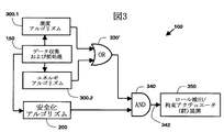
図3を参照すると、車両のロールオーバを検出して、例えば図2に示した装置によって、1つまたは複数の関連する安全拘束アクチュエータ30の作動を制御するロールオーバ検出アルゴリズム100の一実施態様には、データ収集および処理アルゴリズム150、測度アルゴリズム(measures algorithm)300.1、エネルギアルゴリズム300.2、安全化アルゴリズム200、およびそれに応じて安全拘束アクチュエータ(1つまたは複数)30の作動を制御する信号342を生成する、関連するロジック330’、340の組合せが含まれる。
測度アルゴリズム300.1は、ロールオーバ状態を検出するのに、経験則的な、時間域判別処理を使用しており、通常車両の大きな横方向作用力を伴い、比較的速い頭部接触時間(例えば<250msec)を特徴とする、ほとんどのロールオーバ事象に対して、展開時間を短縮する上で有利である。測度アルゴリズム300.1では、フィルタリングされた

Figure 0004317032
信号およびフィルタリングされた
Figure 0004317032
信号の両方を使用して、別の基準と共に展開決定を行うために用いる閾値と比較するための関数が評価される。 Referring to FIG. 3, an embodiment of a rollover detection algorithm 100 that detects rollover of a vehicle and controls the operation of one or more associated safety restraint actuators 30 by, for example, the apparatus shown in FIG. Are signals that control the operation of the data collection and processing algorithm 150, measures algorithm 300.1, energy algorithm 300.2, safety algorithm 200, and safety restraint actuator (s) 30 accordingly. A combination of associated logic 330 ′, 340 that generates 342 is included.
The measure algorithm 300.1 uses an empirical time domain discrimination process to detect the rollover condition, usually with a large lateral force of the vehicle, and a relatively fast head contact time ( For most rollover events characterized by <250 msec), for example, it is advantageous in reducing deployment time. In measure algorithm 300.1, filtered
Figure 0004317032
Signal and filtered
Figure 0004317032
Both signals are used to evaluate a function for comparison with a threshold used to make an expansion decision with another criterion.

エネルギアルゴリズム300.2は、車両のロールオーバ発生過程に関する物理則に基づいて、位相空間判別処理を使用して、ロールオーバ状態を検出するものであり、主として車両の垂直方向力または車両12に対する低い横方向力によって生ずる低速のロール事象に対する信頼性のある展開判断をする上で有利である。エネルギアルゴリズム300.2は、フィルタリングされた角速度信号を利用して、車両12のロール状態を同定し、その瞬間的な全エネルギ(回転運動エネルギと位置エネルギ)と、関連する平衡点を超えて車両をロール回転させるのに要するエネルギとを比較する。エネルギアルゴリズム300.2は、関連する入口基準および出口基準に、フィルタリングされた

Figure 0004317032
信号と、フィルタリングされた
Figure 0004317032
信号の両方を使用する。 The energy algorithm 300.2 detects a rollover state using a phase space discriminating process based on a physical law relating to a vehicle rollover occurrence process, and is mainly low in the vehicle vertical force or the vehicle 12. This is advantageous for making reliable deployment decisions for slow roll events caused by lateral forces. The energy algorithm 300.2 utilizes the filtered angular velocity signal to identify the roll state of the vehicle 12, and to exceed the instantaneous total energy (rotational kinetic energy and potential energy) and the associated equilibrium point. The energy required for rotating the roll is compared. The energy algorithm 300.2 was filtered to the relevant entry and exit criteria
Figure 0004317032
Signal and filtered
Figure 0004317032
Use both signals.

図3には測度アルゴリズム300.1とエネルギアルゴリズム300.2とを組み合わせて使用する場合を示しているが、このことは本質的ではなく、いずれのアルゴリズムも単独で使用することもできることを理解すべきである。しかしながら、アルゴリズムを組み合わせることによって、関連するロールオーバ検出システム10のロバスト性を増大させることができる。この理由は、例えば「縁石走行(curb-trip)」状態のような状態においては、測度アルゴリズム300.1は、エネルギアルゴリズム300.2よりも迅速な判別を実施できるが、これに対して「螺旋状(corkscrew)」、「ランプ状(ramp)」、または「フリップ状(flip)」などのその他の状態においては、エネルギアルゴリズム300.2の方が、測度アルゴリズム300.1よりも迅速な判別が可能である。
測度アルゴリズム300.1およびエネルギアルゴリズム300.2は、互いに独立であるが両者とも、データ収集および処理アルゴリズム150からのフィルタリングされた共通のデータ、すなわちフィルタリングされた

Figure 0004317032
およびフィルタリングされた
Figure 0004317032
のデータを利用する。測度アルゴリズム300.1およびエネルギアルゴリズム300.2の両方とも、関連する入口基準および出口基準に特徴があり、それぞれのアルゴリズムに関連する計算は、それぞれの関連する入口基準が満たされた場合に開始され、それぞれの関連する出口基準が満たされた場合には、これらの計算は停止されて、その後に入口基準が満たされるとリセットされる。 Although FIG. 3 shows a combination of the measure algorithm 300.1 and the energy algorithm 300.2, this is not essential and it is understood that either algorithm can be used alone. Should. However, combining the algorithms can increase the robustness of the associated rollover detection system 10. This is because, for example, in a state such as a “curb-trip” state, the measure algorithm 300.1 can perform a more rapid discrimination than the energy algorithm 300.2, but in contrast to this, the “spiral” In other states, such as “corkscrew”, “ramp”, or “flip”, the energy algorithm 300.2 provides faster discrimination than the measure algorithm 300.1. Is possible.
The measure algorithm 300.1 and the energy algorithm 300.2 are independent of each other, but both are filtered common data from the data collection and processing algorithm 150, ie filtered
Figure 0004317032
And filtered
Figure 0004317032
Use the data. Both measure algorithm 300.1 and energy algorithm 300.2 are characterized by associated entry and exit criteria, and the computation associated with each algorithm is initiated when each associated entry criterion is met. If each associated exit criterion is met, these calculations are stopped and then reset when the entrance criterion is met.

安全化アルゴリズム(safing algorithm)200は、1つまたは複数の対応する安全化拘束アクチュエータ30を展開可能にするために満たさなくてはならない、フィルタリングされた

Figure 0004317032
および/またはフィルタリングされた
Figure 0004317032
に依存する、独立した条件セット、または安全化基準を提供ことによって、ロールオーバ検出システム10の信頼性を向上させることができる。測度アルゴリズム300.1とエネルギアルゴリズム300.2の両方とも、共通の安全化アルゴリズム200によって、それぞれ「安全化」される。安全化アルゴリズム200によって、追加の判別を行い、非ロールオーバ事象に対しての安全拘束アクチュエータ30の不要な作動を緩和することが可能となるが、安全化アルゴリズム200は本質的なものではなく、測度アルゴリズム300.1およびエネルギアルゴリズム300.2は、いずれも単独で使用することも、互いに組み合わせて使用することも可能であり、また安全化アルゴリズム200を伴っても、伴わなくても使用可能であることを理解すべきである。 The safing algorithm 200 is a filtered, which must be satisfied in order for one or more corresponding safeguarded actuators 30 to be deployable.
Figure 0004317032
And / or filtered
Figure 0004317032
By providing an independent set of conditions, or safety criteria, that depend on, the reliability of the rollover detection system 10 can be improved. Both the measure algorithm 300.1 and the energy algorithm 300.2 are each “secured” by the common safety algorithm 200. Although the safety algorithm 200 makes additional determinations and can mitigate unnecessary actuation of the safety restraint actuator 30 for non-rollover events, the safety algorithm 200 is not essential, Both the measure algorithm 300.1 and the energy algorithm 300.2 can be used alone or in combination with each other, and can be used with or without the safety algorithm 200. It should be understood.

ロールオーバ検出アルゴリズム100の作動に際して、データ収集および処理アルゴリズム150からのデータに応じて、測度アルゴリズム300.1または(OR330’)エネルギアルゴリズム300.2が車両のロールオーバ状態を検出し、かつ(AND340)安全化アルゴリズム200が関連する独立の安全化条件が満たされると判断した場合、ステップ(350)において、車両12が実際にロールオーバするかしないにかかわらず、そのロールオーバ事象によって起こり得る関連する車両の乗員への傷害を軽減するために、1つまたは複数の安全拘束アクチュエータ30が展開される。
以下に図3〜7に示すフローチャートを参照して、データ収集および処理アルゴリズム150、安全化アルゴリズム200、測度アリゴリズム300.1およびエネルギアルゴリズム300.2について説明する。図6は、測度アルゴリズム300.1およびエネルギアルゴリズム300.2の両方の一般的なアルゴリズム構造のフローチャートを示しており、測度アルゴリズム300.1とエネルギアルゴリズム300.2の個々の詳細は図8a〜8cに表で示してある。アルゴリズムは数学的に記述してあり、応用例に特有の定数についてはパラメータを用いており、これらのパラメータを、特定の種類の車両について例となる数値とあわせて、図9aおよび9bに示してある。これらのパラメータは通常、例えば車両プラットフォームなどの特定の応用例に適合させるものであること、また図9aおよび9bに示すパラメータの具体的な数値は説明のためだけのものであり、本発明の範囲を限定するものと考えるべきではないことはいうまでもない。
In operation of rollover detection algorithm 100, depending on the data from data collection and processing algorithm 150, measure algorithm 300.1 or (OR 330 ′) energy algorithm 300.2 detects the rollover condition of the vehicle and (AND 340). ) If the safety algorithm 200 determines that the associated independent safety condition is met, in step (350), the relevant association that may occur due to the rollover event, whether or not the vehicle 12 actually rolls over. One or more safety restraint actuators 30 are deployed to reduce injury to vehicle occupants.
The data collection and processing algorithm 150, the security algorithm 200, the measure algorithm 300.1, and the energy algorithm 300.2 will be described below with reference to the flowcharts shown in FIGS. FIG. 6 shows a flowchart of the general algorithm structure of both measure algorithm 300.1 and energy algorithm 300.2, with individual details of measure algorithm 300.1 and energy algorithm 300.2 shown in FIGS. Is shown in the table. The algorithm is described mathematically and uses parameters for constants specific to the application, and these parameters are shown in FIGS. 9a and 9b, along with example values for a particular type of vehicle. is there. These parameters are usually adapted to a particular application, for example a vehicle platform, and the specific numerical values of the parameters shown in FIGS. 9a and 9b are for illustration only and are within the scope of the present invention. It goes without saying that it should not be considered as limiting.

図4を参照すると、データ収集および処理アルゴリズム150は、ステップ(152)において横加速度計18から横加速度成分Aの計測値を取得し、ステップ(158)において角速度センサ20から縦方向角速度ωすなわちロール角速度の計測値を取得する。100回以上のロールオーバ試験のデータから、ロールオーバに伴う角速度ωすなわちロール角速度は、一般に±300度/秒

Figure 0004317032
であり、それに伴う横加速度成分Ay(t)は一般に±20g
Figure 0004317032
の範囲にあることがわかった。これらのそれぞれの限界値を超える横加速度成分A(t)および角速度ωは、それぞれステップ(154)および(160)において、それぞれその値で刈り込まれる。例えば、関連する範囲が±20gの例については、−20g未満の横加速度成分A(t)の測定値は、ステップ(154)においてその値が−20gに設定される。横加速度計18と角速度センサ20の極性は、角速度ω信号および横加速度成分A信号の対応する極性が、ロール発生中は互いに同じになるように設定される。一般に横加速度計18からの信号を刈り込むレベル
Figure 0004317032
は、20gまたは横加速度計18の測定範囲のいずれかの最小値に設定される。同様に、角速度センサ20からの信号を刈り込むレベル
Figure 0004317032
は、300度/秒または角速度センサ20の測定範囲のいずれかの最小値に設定される。 Referring to FIG. 4, the data collection and processing algorithm 150 obtains the measured value of the lateral acceleration component A y from the lateral accelerometer 18 in step (152), and the longitudinal angular velocity ω x from the angular velocity sensor 20 in step (158). That is, the measured value of the roll angular velocity is acquired. From the data of 100 or more rollover tests, the angular velocity ω x accompanying the rollover, that is, the roll angular velocity is generally ± 300 degrees / second.
Figure 0004317032
The resulting lateral acceleration component A y (t) is generally ± 20 g
Figure 0004317032
It was found to be in the range. Lateral acceleration components A y (t) and angular velocities ω x exceeding the respective limit values are trimmed with the values in steps (154) and (160), respectively. For example, for an example where the related range is ± 20 g, the measured value of the lateral acceleration component A y (t) less than −20 g is set to −20 g in step (154). The polarities of the lateral accelerometer 18 and the angular velocity sensor 20 are set such that the corresponding polarities of the angular velocity ω x signal and the lateral acceleration component A y signal are the same during roll generation. Generally the level at which the signal from the lateral accelerometer 18 is trimmed
Figure 0004317032
Is set to the minimum value of either 20 g or the measurement range of the lateral accelerometer 18. Similarly, the level at which the signal from the angular velocity sensor 20 is trimmed
Figure 0004317032
Is set to the minimum value of either 300 degrees / second or the measurement range of the angular velocity sensor 20.

横加速度計18および角速度センサ20それぞれからの、横加速度成分Aおよび角速度ωの生データは、それぞれステップ(156)および(162)において、それぞれのフィルタ22、24によってフィルタリングされて、それぞれフィルタリングされた

Figure 0004317032
およびフィルタリングされた
Figure 0004317032
となる。フィルタリングされた測定値を使用することは、ロール判別アルゴリズムの誤開始を避けること、および測度アルゴリズム300.1およびエネルギアルゴリズム300.2による関連する判別処理を改善することにおいて有利である。フィルタ22、23は、例えば10から15ミリ秒の間の移動平均ウインドTAvgを有する移動平均フィルタとして、迅速な信号応答とノイズ低減とを適切に妥協させる。例えば、プロセッサ26は、以下に仮定するように、角速度ω信号および横加速度成分A信号を、サンプリング速度2500Hz(サンプリング周期dt=0.4ミリ秒に対応)、ウインド12.8ミリ秒で均一にサンプリングし、各信号についての移動平均が、収集された最新の32のサンプルから計算される。移動平均の個々のサンプルは、通常均一に重みづけされるが、別の選択として不均一に重み付けすることもできる。 The raw data of the lateral acceleration component A y and the angular velocity ω x from the lateral accelerometer 18 and the angular velocity sensor 20 are respectively filtered by the respective filters 22 and 24 in steps (156) and (162), respectively. Was
Figure 0004317032
And filtered
Figure 0004317032
It becomes. Using filtered measurements is advantageous in avoiding false start of the role discrimination algorithm and improving the associated discrimination process by the measure algorithm 300.1 and energy algorithm 300.2. Filters 22, 23, for example, as a moving average filter having a moving average window T Avg between 10 and 15 milliseconds, properly compromises rapid signal response and noise reduction. For example, as will be assumed below, the processor 26 generates an angular velocity ω x signal and a lateral acceleration component A y signal at a sampling rate of 2500 Hz (corresponding to a sampling period dt = 0.4 ms) at a window of 12.8 ms. Sampling uniformly, a moving average for each signal is calculated from the last 32 samples collected. The individual samples of the moving average are usually weighted uniformly, but can be weighted non-uniformly as another option.

一般に、横加速度計18および角速度センサ20は、オフセットおよび/またはドリフト誤差(一般にセンサオフセット誤差と呼ばれる)を示す可能性があり、これを補償しない限り、関連するロール検出誤差が生じる可能性がある。このセンサオフセット誤差は、フィルタリングされた

Figure 0004317032
およびフィルタリングされた
Figure 0004317032
を出力する上記の移動平均フィルタよりも、大幅に低い有効カットオフ周波数、あるいは言い換えると大幅に大きい有効フィルタ時間定数を有する、関連するフィルタを用いてセンサ計測値をフィルタリングすることによって評価される。例えば、
Figure 0004317032
は、ステップ(168)および(170)におけるそれぞれの移動平均フィルタによって、関連する角速度ωおよび横加速度成分Aそれぞれの計測生データをフィルタリングして得られ、この各移動平均フィルタは関連するウインド幅
Figure 0004317032
例えば約4秒を有する。 In general, the lateral accelerometer 18 and the angular velocity sensor 20 may exhibit offset and / or drift errors (commonly referred to as sensor offset errors), and associated roll detection errors may occur unless this is compensated for. . This sensor offset error is filtered
Figure 0004317032
And filtered
Figure 0004317032
Is evaluated by filtering the sensor measurements with an associated filter that has a significantly lower effective cut-off frequency, or in other words, a significantly larger effective filter time constant, than the moving average filter described above. For example,
Figure 0004317032
Is obtained by filtering the measured raw data of the respective angular velocity ω x and lateral acceleration component A y by the respective moving average filters in steps (168) and (170), each moving average filter being associated with the associated window. width
Figure 0004317032
For example, having about 4 seconds.

ステップ(164)から、フィルタリングされた

Figure 0004317032
の値は測度アルゴリズム300.1およびエネルギアルゴリズム300.2の両方が開始されていないときにのみ更新され、これは関連する両フラグONGOING_EVENT_FLAGs(進行イベントフラグ)、すなわちONGOING_MEASURES_EVENT_FLAG(進行メジャーズイベントフラグ)およびONGOING_ENERGY_EVENT_FLAG(進行エネルギイベントフラグ)の両方が設定されていないことで示される。したがって、ステップ(166)において、比較的長時間のフィルタリングを施された
Figure 0004317032
の値は、関連する横加速度成分Aおよび角速度ωが、関連するセンサオフセット値と大幅に異なる可能性のある時間間隔においては、更新されない。 Filtered from step (164)
Figure 0004317032
The value of is updated only when both the measure algorithm 300.1 and the energy algorithm 300.2 are not started, which are both related flags ONGOING_EVENT_FLAGs (progression event flags), namely ONGOING_MEASURES_EVENT_FLAG (progression majors event flag) and ONGOING_ENERGY_EVENT_FLAG It is indicated that both (progress energy event flag) are not set. Therefore, in step (166), a relatively long filtering was performed.
Figure 0004317032
Is not updated in time intervals where the associated lateral acceleration component A y and angular velocity ω x can be significantly different from the associated sensor offset value.

図4では、角速度ωの収集および処理の以前に、横加速度成分Aの収集および処理を示しているが、相対的な順序は逆になることもあり、またこれらの操作が並行して実行されることもあることを理解すべきである。
測度アルゴリズム300.1、エネルギアルゴリズム300.2、および安全化アルゴリズム200のそれぞれにおいては、対応するセンサオフセット、すなわち

Figure 0004317032
をそれぞれ減じることにより補償した、フィルタリングされた
Figure 0004317032
およびフィルタリングされた
Figure 0004317032
を使用することによって、対応する補償横加速度成分
Figure 0004317032
および補償角速度
Figure 0004317032
がそれぞれ求められる。 In FIG. 4, the collection and processing of the lateral acceleration component A x is shown before the collection and processing of the angular velocity ω x , but the relative order may be reversed, and these operations are performed in parallel. It should be understood that it may be performed.
In each of the measure algorithm 300.1, energy algorithm 300.2, and safety algorithm 200, the corresponding sensor offset, i.e.
Figure 0004317032
Filtered, compensated by subtracting each
Figure 0004317032
And filtered
Figure 0004317032
By using the corresponding compensated lateral acceleration component
Figure 0004317032
And compensation angular velocity
Figure 0004317032
Is required.

図5を参照すると、安全化アルゴリズム200は、ステップ(202)から始まり、ここで関連する両フラグSAFING_EVENT_FLAGs(安全化イベントフラグ)、すなわちACCELERATION_SAFING_EVENT_FLAG(加速度安全化イベントフラグ) および ROLL_SAFING_EVENT_FLAG(ロール安全化イベントフラグ)が最初にリセットされる。次いで、ステップ(204)において、ONGOING_EVENT_FLAGsフラグ(すなわちONGOING_MEASURES_EVENT_FLAGまたはONGOING_ENERGY_EVENT_FLAG)のいずれかが設定されていることでわかるように、測度アルゴリズム300.1またはエネルギアルゴリズム300.2のいずれかが開始されている場合には、次のステップ(206)において、

Figure 0004317032
の絶対値が第3の加速度閾値
Figure 0004317032
よりも大きい場合に、次のステップ(208)において、ACCELERATION_SAFING_EVENT_FLAGが設定される。そうでない場合には、ステップ(204)から、ステップ(202)に戻り処理が反復される。 Referring to FIG. 5, the safety algorithm 200 begins at step (202) where both relevant flags SAFING_EVENT_FLAGs (safety event flags), namely ACCELERATION_SAFING_EVENT_FLAG (acceleration safety event flag) and ROLL_SAFING_EVENT_FLAG (roll safety event flag). ) Is reset first. If either measure algorithm 300.1 or energy algorithm 300.2 is then started, as can be seen in step (204), either the ONGOING_EVENT_FLAGs flag (ie, ONGOING_MEASURES_EVENT_FLAG or ONGOING_ENERGY_EVENT_FLAG) is set In the next step (206),
Figure 0004317032
Is the third acceleration threshold
Figure 0004317032
If greater than, in the next step (208), ACCELERATION_SAFING_EVENT_FLAG is set. Otherwise, the process is repeated from step (204) to step (202).

ステップ(208)に続いて、あるいはステップ(206)に続いて、ステップ(210)において、

Figure 0004317032
の絶対値が第3の角速度閾値
Figure 0004317032
よりも大きい場合に、ステップ(212)でROLL_SAFING_EVENT_FLAGが設定される。これに次いで、あるいはステップ(210)から、ステップ(204)に戻り反復処理される。したがって、測度アルゴリズム300.1およびエネルギアルゴリズム300.2の少なくとも1つに入った後で、かつ両者から出る以前に、安全化アルゴリズム200に関連する横加速度および角速度の条件が満たされると、それが必ずしも同時でなくても、それぞれの関連する安全化イベントフラグSAFING_EVENT_FLAGsが次に設定されて、測度アルゴリズム300.1またはエネルギアルゴリズム300.2のいずれかによるロール状態の検出に応じて1つまたは複数の安全拘束アクチュエータの展開が可能となる。それぞれのSAFING_EVENT_FLAGsは個別に設定、またはラッチされるが、両者は同時にリセットされると共に、測度アルゴリズム300.1またはエネルギアルゴリズム300.2に応じて1つまたは複数の関連する安全拘束アクチュエータ30を作動させるためには、両方が設定されていなくてはならない。 Following step (208) or following step (206), at step (210),
Figure 0004317032
Is the third angular velocity threshold
Figure 0004317032
Is greater than ROLL_SAFING_EVENT_FLAG is set in step (212). Following this, or from step (210), it returns to step (204) and is iteratively processed. Therefore, after entering at least one of the measure algorithm 300.1 and the energy algorithm 300.2 and before exiting from both, if the lateral acceleration and angular velocity conditions associated with the safety algorithm 200 are met, Although not necessarily simultaneous, each associated safety event flag SAFING_EVENT_FLAGs is then set to one or more depending on the detection of the roll condition by either the measure algorithm 300.1 or the energy algorithm 300.2. The deployment of the safety restraint actuator becomes possible. Each SAFING_EVENT_FLAGs is set or latched individually, but both are reset at the same time and activate one or more associated safety restraint actuators 30 depending on the measure algorithm 300.1 or energy algorithm 300.2 For this to happen, both must be set.

代替案として、安全化アルゴリズム200を、前記のフラグの1つだけと、関連する基準だけを組み込むように適合させることによって、安全化基準が、測度アルゴリズム300.1またはエネルギアルゴリズム300.2のいずれかの開始時刻に続く、第1ポイント時刻における第3の加速度閾値

Figure 0004317032
よりも大きい
Figure 0004317032
の絶対値と、開始時刻に続く第2ポイント時刻における第3の角速度閾値
Figure 0004317032
よりも大きい
Figure 0004317032
の絶対値の、少なくとも一方に応答するようにしてもよく、この場合に開始時刻とは、関連する測度アルゴリズム300.1またはエネルギアルゴリズム300.2について、関連する入口基準が満たされる時刻であり、開始時刻に続く、第1ポイントおよび第2ポイント時刻は互いに任意である。例えば、エネルギアルゴリズム300.2は、エネルギアルゴリズム300.2の開始時刻に続くある時刻における、第3の加速度閾値
Figure 0004317032
よりも大きな
Figure 0004317032
だけに応答して「安全化」させることもできる。 As an alternative, by adapting the safety algorithm 200 to incorporate only one of the aforementioned flags and only the relevant criteria, the safety criteria can be either the measure algorithm 300.1 or the energy algorithm 300.2. The third acceleration threshold value at the first point time following the start time
Figure 0004317032
Bigger than
Figure 0004317032
And the third angular velocity threshold at the second point time following the start time
Figure 0004317032
Bigger than
Figure 0004317032
In which case the start time is the time at which the relevant entry criteria are met for the associated measure algorithm 300.1 or energy algorithm 300.2; The first point time and the second point time following the start time are arbitrary. For example, the energy algorithm 300.2 may include a third acceleration threshold at a time following the start time of the energy algorithm 300.2.
Figure 0004317032
Bigger than
Figure 0004317032
It can also be made "safe" in response to only.

ロールオーバ検出システム10は、測度アルゴリズム300.1またはエネルギアルゴリズム300.2の実装用とは別個のマイクロプセッサを用いて安全化アルゴリズム200を実装することによって信頼性を改善するように適合させてもよく、この場合には安全化アルゴリズム200が進行イベントフラグONGOING_EVENT_FLAGsを認識しない場合には、これらのフラグに応じて安全化イベントフラグSAFING_EVENT_FLAGsをリセットするかわりに、1つまたは複数の安全化アクチュエータ30が展開されるまで、あるいは両アルゴリズムが終了してしまうことになるまで、安全化条件が作動状態に維持されるように、一方の安全化基準が最後に満たされた時刻から、ある遅延、例えば

Figure 0004317032
(例えば12秒)を設けてリセットしてもよい。 The rollover detection system 10 may be adapted to improve reliability by implementing the safety algorithm 200 using a microprocessor separate from that for implementing the measure algorithm 300.1 or energy algorithm 300.2. Well, in this case, if the safety algorithm 200 does not recognize the progress event flags ONGOING_EVENT_FLAGs, instead of resetting the safety event flag SAFING_EVENT_FLAGs according to these flags, one or more safety actuators 30 are deployed. From the time when one of the safety criteria was last met, e.g., so that the safety condition remains operational until both algorithms are finished or until both algorithms have ended.
Figure 0004317032
(For example, 12 seconds) may be provided and reset.

測度アルゴリズム300.1およびエネルギアルゴリズム300.2のそれぞれは、図6に示す全体アルゴリズム構造に従って作動し、これらのアルゴリズムはそれぞれ、すべて参照番号300で示してある。特定の参照番号に小数点番号をつけることによって、個別のアルゴリズムを参照することにする。例えば、一般的な全体処理は参照番号300で表し、測度アルゴリズムは300.1で、エネルギアルゴリズムは300.2で表す。別の例をあげると、全般のアルゴリズム計算ステップは参照番号326で表すが、参照番号326.1は測度アルゴリズム300.1のアルゴリズム計算ステップを特に表し、参照番号362.2はエネルギアルゴリズム300.2のアルゴリズム計算ステップを表す。特定のアルゴリズムステップに関連する特定の方程式は、各アルゴリズムについて、図8a〜8cに表形式で示し、関連するパラメータとその例としての値を、図9a、9bに表形式で示してある。   Each of the measure algorithm 300.1 and the energy algorithm 300.2 operates according to the overall algorithm structure shown in FIG. 6, and each of these algorithms is designated by the reference numeral 300. We will refer to individual algorithms by attaching a decimal number to a particular reference number. For example, the general overall process is represented by reference number 300, the measure algorithm is 300.1, and the energy algorithm is 300.2. As another example, the general algorithm calculation step is represented by reference number 326, while reference number 326.1 specifically represents the algorithm calculation step of measure algorithm 300.1, and reference number 362.2 represents energy algorithm 300.2. Represents the algorithm calculation step. The specific equations associated with a particular algorithm step are shown in tabular form in FIGS. 8a-8c for each algorithm, and the associated parameters and example values are shown in tabular form in FIGS. 9a, 9b.

図6を参照すると、全体ロール処理アルゴリズムはステップ(302)から開始され、対応する進行イベントフラグONGOING_EVENT_FLAGがリセットされる。このONGOING_EVENT_FLAGが設定されることは、ロール処理アルゴリズムの入口基準が満たされ、対応する出口基準は満たされず、したがって関連するアルゴリズムが作動状態であることを示す。次いでステップ(150)において、前述のデータ収集および処理アルゴリズム150に従って、このアルゴリズムで用いられる関連データが、収集かつ処理される。次いでステップ(304)において、ONGOING_EVENT_FLAGが設定されていない場合、つまり潜在的なロール事象からのデータを処理中ではなく、車両12にロール事象が生じていないことを示す場合には、ステップ(306)において1組の入口基準が評価されて関連する閾値と比較され、入口基準が満たされる場合には、ステップ(308)においてONGOING_EVENT_FLAGが設定され、かつステップ(310)において、例えばアルゴリズム関連する様々な動的変数を初期化することによって、アルゴリズムが開始される。   Referring to FIG. 6, the entire roll processing algorithm starts from step (302), and the corresponding progress event flag ONOING_EVENT_FLAG is reset. Setting this ONGOING_EVENT_FLAG indicates that the entry criterion of the roll processing algorithm is satisfied, the corresponding exit criterion is not satisfied, and therefore the associated algorithm is active. Then, in step (150), according to the data collection and processing algorithm 150 described above, the relevant data used in this algorithm is collected and processed. Then, in step (304), if ONGOING_EVENT_FLAG is not set, that is, if data from a potential roll event is not being processed, indicating that no roll event has occurred in vehicle 12, step (306) In step 308, a set of entrance criteria is evaluated and compared to an associated threshold, and if the entrance criteria are met, ONGOING_EVENT_FLAG is set in step (308), and in step (310), for example, various algorithm-related actions. The algorithm is started by initializing the static variables.

あるいはステップ(304)から、進行イベントフラグONGOING_EVENT_FLAGが設定されており、潜在的なロール事象からのデータが処理中であることを示す場合には、ステップ(312)において、関連する時間の測度、例えばサンプル計数が更新されて、ステップ(400)で、新規に収集されたデータが評価されて、センサ(つまり横加速度計18または角速度センサ20)を再較正する必要があるかどうかが判断される。ステップ(400)に関連する処理を図7に示してあり、以下により詳細を説明する。
ステップ(400)から、1つ又は複数のセンサが再較正を必要とする場合、ステップ(314)において再較正を必要とする1つまたは複数のセンサが再較正される。例えば、横加速度計18および角速度センサ20の両方が試験可能であり、既知の刺激をセンサに与え、対応するセンサ出力が既知の刺激と一致するように較正することができる。例えば、横加速度計18が、マイクロマシン加工による、スプリング要素の梁で懸架されたマス要素を含むものであれば、マス要素とハウジングの間に静電場を印加して、基準加速度レベルに相当する量だけ梁を撓ませる。
Alternatively, from step (304), if the progress event flag ONGOING_EVENT_FLAG is set to indicate that data from a potential roll event is being processed, then in step (312) the associated time measure, eg The sample count is updated and, in step (400), the newly collected data is evaluated to determine if the sensor (ie, lateral accelerometer 18 or angular velocity sensor 20) needs to be recalibrated. The process associated with step (400) is shown in FIG. 7 and will be described in more detail below.
From step (400), if one or more sensors require recalibration, in step (314), the one or more sensors that require recalibration are recalibrated. For example, both the lateral accelerometer 18 and the angular velocity sensor 20 can be tested and can be calibrated such that a known stimulus is applied to the sensor and the corresponding sensor output matches the known stimulus. For example, if the lateral accelerometer 18 includes a mass element suspended by a beam of a spring element by micromachining, an amount corresponding to a reference acceleration level by applying an electrostatic field between the mass element and the housing. Only bend the beam.

次いで、歪センシング要素からの出力が、基準加速度レベルに一致するように較正係数を計算する。ステップ(316)において、ステップ(314)の処理が、1つまたは複数のセンサが故障していることを示す場合、例えばセンサに試験刺激を加えるか否かにかかわらず、出力に実質的に変化がない場合には、ステップ(318)において、故障状態が設定され、警報装置、例えばライトが作動して車両12のドライバに警告し、ロールオーバ検出システムによる安全拘束アクチュエータ30の展開を不能とする。あるいはステップ(316)から、すなわち横加速度計18および角速度センサ20の両方ともが故障していない場合には、ステップ(320)において、両フラグONGOING_EVENT_FLAGs、すなわちONGOING_MEASURES_EVENT_FLAGおよびONGOING_ENERGY_EVENT_FLAGが、少なくとも1つのセンサの再較正が行われたことに応じてリセットされて、ステップ(150)から新たな処理が反復される。   A calibration factor is then calculated so that the output from the strain sensing element matches the reference acceleration level. In step (316), if the process of step (314) indicates that one or more sensors are faulty, for example, whether or not a test stimulus is applied to the sensors, the output is substantially changed. If not, in step (318) a fault condition is set and an alarm device, for example a light, is activated to alert the driver of the vehicle 12 and disable the deployment of the safety restraint actuator 30 by the rollover detection system. . Alternatively, from step (316), i.e., if both lateral accelerometer 18 and angular velocity sensor 20 have not failed, in step (320) both flags ONGOING_EVENT_FLAGs, i.e. ONGOING_MEASURES_EVENT_FLAG and ONGOING_ENERGY_EVENT_FLAG, It is reset in response to the calibration being performed, and a new process is repeated from step (150).

あるいはステップ(400)から、どのセンサも再較正の必要がない場合には、ステップ(322)において出口基準が評価されて、ステップ(306)における入口基準を再び満たしてアリゴリズムに再び入る時刻まで、アルゴリズムから退出するかどうかが決定される。ステップ(322)からは、出口基準が満たされる場合には、ステップ(324)においてアルゴリズムがエネルギアルゴリズム300.2であり、かつエネルギアルゴリズム300.2がステップ(306)で連続して登録され、かつ次いでタイムアウト

Figure 0004317032
の結果ステップ(322)で退出し、ステップ(322)で退出した直後に、例えばアルゴリズムの次回反復中にステップ(306)で再び入る場合には、ステップ(322)においてp回(例えばp=3)連続で退出した後に、上述のようにステップ(324)からの処理が継続されて、センサが診断され、必要な場合には再較正される。あるいはステップ(324)から、関連する進行フラグONGOING_EVENT_FLAG、すなわちONGOING_MEASURES_EVENT_FLAGまたはONGOING_ENERGY_EVENT_FLAGがステップ(320)でリセットされて、ステップ(150)から新しい処理が反復される。 Alternatively, from step (400), if no sensors need to be recalibrated, the exit criteria are evaluated in step (322) until the time when the entrance criteria in step (306) are re-filled and the algorithm is re-entered. It is determined whether to exit the algorithm. From step (322), if the exit criteria are met, in step (324) the algorithm is energy algorithm 300.2, and energy algorithm 300.2 is continuously registered in step (306), and Then timeout
Figure 0004317032
As a result of exiting at step (322) and immediately after exiting at step (322), for example, when entering again at step (306) during the next iteration of the algorithm, at step (322) p times (eg, p = 3) ) After exiting continuously, processing from step (324) continues as described above, and the sensor is diagnosed and recalibrated if necessary. Alternatively, from step (324), the associated progress flag ONGOING_EVENT_FLAG, ie, ONGOING_MEASURES_EVENT_FLAG or ONGOING_ENERGY_EVENT_FLAG is reset at step (320) and the new process is repeated from step (150).

あるいは、ステップ(322)からは、アルゴリズムがステップ(306)で登録され、かつステップ(322)で退出していない場合に、ステップ(310)またはステップ(312)のいずれかからの時間測度の特定の値にしたがって、アルゴリズムの特定の反復について、関連するアルゴリズム計算が実施される。次いで、ステップ(330)において、関連するアルゴリズム検出基準が、アルゴリズムの特定の反復において満たされ、かつステップ(340)において安全化イベントフラグSAFING_EVENT_FLAG(s)、すなわちACCELERATION_SAFING_EVENT_FLAGおよび ROLL_SAFING_EVENT_FLAGが設定されている場合には、ステップ(350)においてロール事象が検出され、関連する安全拘束アクチュエータ30が作動される。逆に、ステップ(330)においてアルゴリズム検出基準が満たされない場合、またはステップ(340)において、すべての安全化イベントフラグが非設定であり、関連する安全化基準が、測度アルゴリズム300.1またはエネルギアルゴリズム300.2の実行中のある時刻において満たされない場合には、ステップ(150)から始まる次の反復が継続される。   Alternatively, from step (322), the time measure from either step (310) or step (312) is specified if the algorithm was registered at step (306) and not exited at step (322). Depending on the value of, the associated algorithm calculation is performed for a particular iteration of the algorithm. Then, in step (330), if the relevant algorithm detection criteria are met in a particular iteration of the algorithm and the safety event flag SAFING_EVENT_FLAG (s), ie ACCELERATION_SAFING_EVENT_FLAG and ROLL_SAFING_EVENT_FLAG, is set in step (340) In step (350), a roll event is detected and the associated safety restraint actuator 30 is activated. Conversely, if the algorithm detection criteria are not met in step (330), or in step (340), all the safety event flags are unset and the associated safety criteria are either the measure algorithm 300.1 or the energy algorithm. If not satisfied at some time during the execution of 300.2, the next iteration starting at step (150) is continued.

測度アルゴリズム300.1およびエネルギアルゴリズム300.2の両方とも、データ収集および処理アルゴリズム150からの横加速度成分Aおよび縦方向角速度ω の計測値に依存するが、各アルゴリズムに関連するその他の変数およびパラメータは互いに独立であり、同様にステップ(306)における関連する入口基準、ステップ(310)におけるアルゴリズム初期化、ステップ(322)における関連する出口基準、ステップ(326)におけるアルゴリズム計算、およびステップ(330)におけるアルゴリズム判断基準も独立であり、これらのすべてについての例を図8a,8b、8c、9a、および9bに詳細に示してある。例えば、各アルゴリズムは開始からの時間測度を決定し、縦方向角速度ωの計測値を積分することによってロール角の測度を計算するが、それぞれのロール角の測度と同様に、これらのそれぞれの時間測度は互いに独立である。測度アルゴリズム300.1およびエネルギアルゴリズム300.2の両方とも、それぞれのアルゴリズムによる処理を開始するときに、初期には車両は水平である(すなわちθ(tentrance)=0)と仮定している。 Both the measure algorithm 300.1 and the energy algorithm 300.2 depend on measurements of the lateral acceleration component A y and the longitudinal angular velocity ω x from the data collection and processing algorithm 150, but other variables associated with each algorithm. And parameters are independent of each other, as well as relevant entry criteria in step (306), algorithm initialization in step (310), relevant exit criteria in step (322), algorithm computation in step (326), and step ( The algorithm criteria in 330) are also independent, examples of all of which are shown in detail in FIGS. 8a, 8b, 8c, 9a and 9b. For example, each algorithm determines a time measure from the start and calculates a roll angle measure by integrating the measured values of the longitudinal angular velocity ω x , as well as their respective roll angle measures. Time measures are independent of each other. Both measure algorithm 300.1 and energy algorithm 300.2 assume that the vehicle is initially horizontal (ie, θ (t entrance ) = 0) when processing by the respective algorithm begins.

横方向加速度計18または角速度センサ20のいずれかが再較正を必要とするかどうかを判断する処理400を図7に示してある。ステップ(402)、(404)、(406)および(408)において、フィルタリングされた

Figure 0004317032
の絶対値が、関連する時間間隔
Figure 0004317032
の間、第4の角速度閾値
Figure 0004317032
を連続的に超える場合には、ステップ(410)において角速度センサ20の再較正の信号が出される。あるいは、ステップ(412)、(414)、(416)、(418)および(420)において、測度アルゴリズムからのロール角の絶対値θか、またはエネルギアルゴリズム300.2からのロール角θのいずれかが、関連する時間間隔
Figure 0004317032
の間、ロール角閾値
Figure 0004317032
を超える場合には、ステップ(410)において角速度センサ20の再較正の信号が出される。あるいはステップ(422)において、角速度センサ20の再較正の信号は出されない。ステップ(424)、(426)、(428)および(430)において、フィルタリングされた
Figure 0004317032
の絶対値が、第4の横加速度閾値
Figure 0004317032
を、関連する時間間隔
Figure 0004317032
の間、連続的に超える場合には、ステップ(432)において横加速度計18の再較正の信号が出される。そうでない場合には、ステップ(434)において、横加速度計18の再較正の信号は出されない。ステップ(410)または(432)のいずれかで再較正の信号が出された場合には、上記のようにステップ(314)から処理が継続される。そうでない場合には、センサ再較正の信号は出されず、上記のようにステップ(322)から処理が継続される。 A process 400 for determining whether either the lateral accelerometer 18 or the angular velocity sensor 20 requires recalibration is shown in FIG. Filtered in steps (402), (404), (406) and (408)
Figure 0004317032
Absolute value of the associated time interval
Figure 0004317032
The fourth angular velocity threshold during
Figure 0004317032
Is continuously exceeded, a signal for recalibration of the angular velocity sensor 20 is issued in step (410). Alternatively, in steps (412), (414), (416), (418) and (420), the absolute value of the roll angle θ M from the measure algorithm or the roll angle θ E from the energy algorithm 300.2 Either is the relevant time interval
Figure 0004317032
Roll angle threshold during
Figure 0004317032
Is exceeded, a signal for recalibration of the angular velocity sensor 20 is issued in step (410). Alternatively, in step (422), a signal for recalibration of the angular velocity sensor 20 is not issued. Filtered in steps (424), (426), (428) and (430)
Figure 0004317032
Is the fourth lateral acceleration threshold value.
Figure 0004317032
The relevant time interval
Figure 0004317032
If it exceeds continuously during step 432, a signal for recalibration of the lateral accelerometer 18 is issued in step (432). Otherwise, in step (434), no signal for recalibration of the lateral accelerometer 18 is issued. If a recalibration signal is issued in either step (410) or (432), processing continues from step (314) as described above. Otherwise, no sensor recalibration signal is issued and processing continues from step (322) as described above.

次に図6、図8a〜8c、および図9a,9bを参照して、測度アルゴリズム300.1についてより詳細に論じるが、図6のステップ番号は、その関連を示すために、ここでは「.1」のような添え字をつけてある。測度アルゴリズム300.1の進行イベントフラグONGOING_EVENT_FLAGは、進行測度イベントフラグONGOING_MEASURES_EVENT_FLAGと呼び、ステップ(306.1)で入口基準が満たされると、ステップ(308.1)で設定され、ステップ(322.1)で出口基準が満たされるとステップ(320.1)でリセットされる。進行測度イベントフラグONGOING_MEASURES_EVENT_FLAGは例えば、測度アルゴリズム300.1を実装するための、関連するプロセッサ26のメモリ28内の特定の場所に対応することもある。ステップ(322.1)に続いて、アルゴリズムに入るとその後は、ステップ(322.1)で測度アルゴリズム300.1の出口基準が満たされるか、またはロール事象が検出され安全拘束アクチュエータ30が展開されるまで、測度アルゴリズム300.1からは出ることはない。さらに、測度イベント出口基準が満たされて、測度アルゴリズム300.1から出た後は、測度アルゴリズム300.1は、関連する測度イベント入口基準がその後に満たされる場合には、再び入ることができる。   The measure algorithm 300.1 will now be discussed in more detail with reference to FIGS. 6, 8a-8c, and FIGS. 9a, 9b, but the step numbers in FIG. A subscript such as “1” is attached. The progress event flag ONGOING_EVENT_FLAG of the measure algorithm 300.1 is called the progress measure event flag ONGOING_MEASURES_EVENT_FLAG. When the entrance criterion is satisfied in step (306.1), it is set in step (308.1), and step (322.1). If the exit criterion is satisfied in step (320.1), it is reset. The progress measure event flag ONGOING_MEASURES_EVENT_FLAG may correspond to a particular location in the memory 28 of the associated processor 26, for example, for implementing the measure algorithm 300.1. Following the step (322.1), upon entering the algorithm, after that, the exit criterion of the measure algorithm 300.1 is met in step (322.1) or a roll event is detected and the safety restraint actuator 30 is deployed. Until then, measure algorithm 300.1 will not leave. Further, after the measure event exit criteria are met and exit from the measure algorithm 300.1, the measure algorithm 300.1 may reenter if the associated measure event entry criteria are subsequently met.

ステップ(306.1)における、測度アルゴリズム300.1の入口基準は例えば、

Figure 0004317032
の絶対値が第1の加速度閾値
Figure 0004317032
より大きい、すなわち
Figure 0004317032
であることである。ある特定の車両の例としては、実際のロールオーバのデータに基づいて、第1の加速度閾値は、約1.4gに設定された。この閾値は、測度アルゴリズム300.1の他のパラメータ値と同様に、一般に特定の関連する車両の特性または車両のクラスに依存すること、および特定のロールオーバ検出システム10に用いる特定の値は、関連する車両の12の特性または車両のクラスに応じて調節することによって判別能力を改善することができることに留意すべきである。 The entry criterion of the measure algorithm 300.1 in step (306.1) is, for example:
Figure 0004317032
Is the first acceleration threshold
Figure 0004317032
Greater than
Figure 0004317032
It is to be. As an example of a particular vehicle, based on actual rollover data, the first acceleration threshold was set to about 1.4 g. This threshold, like other parameter values of the measure algorithm 300.1, generally depends on a particular relevant vehicle characteristic or vehicle class, and the particular value used for a particular rollover detection system 10 is: It should be noted that the discriminating ability can be improved by adjusting according to the 12 characteristics of the vehicle concerned or the class of vehicle.

ステップ(310.1)においては、ステップ(308.1)に続いて測度アルゴリズム300.1に最初に入ると、測度アルゴリズム300.1が初期化される。イベントサンプル数nMおよび角度位置の値θ(nM−1)および測度関数R(nM−1)が、例えばゼロ値に初期化される。またイベント入口時刻の直前のサンプル時刻t(−1)が、現在時刻tに初期化された、測度イベント入口時刻t(0)の値に初期化され、かつアルゴリズム入口からの時間間隔Δt(0)がゼロ値に初期化される。ここで用いた上添え字「M」は、ここでは測度アルゴリズム300.1に関連する変数を表す。 In step (310.1), when the measure algorithm 300.1 is first entered following step (308.1), the measure algorithm 300.1 is initialized. The number of event samples n M, the value θ M (n M −1) of the angular position, and the measure function R (n M −1) are initialized to, for example, zero values. The sample time t M (−1) immediately before the event entry time is initialized to the value of the measure event entry time t M (0), which is initialized at the current time t, and the time interval Δt from the algorithm entry. M (0) is initialized to a zero value. The superscript “M” used here represents a variable related to the measure algorithm 300.1.

測度アルゴリズム300.1の後続の反復時に、ステップ(304.1)において進行測度イベントフラグが設定され、次いでステップ(312.1)においてイベントサンプル数nMが増分され、関連する現行サンプル時刻

Figure 0004317032
が、現行時刻tに等しく設定され、測度イベント時間Δtが測度イベント入口時刻t(0)から現行時刻
Figure 0004317032
までの時間間隔として、以下のように計算される。
Figure 0004317032
ステップ(322.1)における、測度アルゴリズム300.1の出口基準は、例えばアルゴリズム入口からの時間間隔
Figure 0004317032
が、時間間隔閾値
Figure 0004317032
より大きいこと、すなわち
Figure 0004317032
となることである。特定型式の車両の例については、実際のロールデータに基づいて、時間間隔閾値
Figure 0004317032
は約165ミリ秒に設定された。測度アルゴリズム300.1から出ると、進行測度イベントフラグONGOING_MEASURES_EVENT_FLAGはステップ(320.1)でリセットされ、これによって、その後にステップ(306.1)において入口基準が満たされるまでの間、ステップ(310.1)で測度アルゴリズム300.1に関連する変数が初期化される。 During subsequent iterations of the measure algorithm 300.1, the progress measure event flag is set in step (304.1), then the number of event samples n M is incremented in step (312.1) and the associated current sample time.
Figure 0004317032
Is set equal to the current time t, and the measure event time Δt M is the current time from the measure event entry time t M (0).
Figure 0004317032
Is calculated as follows.
Figure 0004317032
The exit criterion of the measure algorithm 300.1 in step (322.1) is, for example, the time interval from the algorithm entry
Figure 0004317032
Is the time interval threshold
Figure 0004317032
Greater than, i.e.
Figure 0004317032
It is to become. For examples of specific types of vehicles, the time interval threshold is based on actual roll data.
Figure 0004317032
Was set to about 165 milliseconds. Upon exiting from the measure algorithm 300.1, the progress measure event flag ONGOING_MEASURES_EVENT_FLAG is reset in step (320.1), so that step (310. In 1), variables associated with the measure algorithm 300.1 are initialized.

ステップ(322.1)において、出口基準が満たされない場合には、アルゴリズム計算はステップ(326.1)において測度アルゴリズム300.1の特定の反復に対して以下のように更新される。
最初に、補償された符号付の角速度値を積分することによって、角度位置θが以下のように推定される。

Figure 0004317032
ここで、積分時間ステップdtは、現行反復における時刻
Figure 0004317032
と、前回反復における時刻との差
Figure 0004317032
として求め、この差はサンプリング速度が一様であれば、以下のように一定値となる。
Figure 0004317032
また、
Figure 0004317032
は以下の式で求められる。
Figure 0004317032
In step (322.1), if the exit criteria are not met, the algorithm calculation is updated in step (326.1) for a particular iteration of measure algorithm 300.1 as follows.
First, by integrating the compensated signed angular velocity value, the angular position θ M is estimated as follows:
Figure 0004317032
Where the integration time step dt is the time in the current iteration
Figure 0004317032
And the time difference from the previous iteration
Figure 0004317032
If the sampling rate is uniform, this difference becomes a constant value as follows.
Figure 0004317032
Also,
Figure 0004317032
Is obtained by the following equation.
Figure 0004317032

次に測度関数Rが推定され、これは良度指数(figure-of-merit)FOMを計算するために用いられる。測度関数Rは以下のように求められる。

Figure 0004317032
測度関数の第1項は、ダンピング項であり、前回値R(nM-1)にダンピング係数
Figure 0004317032
を乗じた積からなる。ダンピングのレベルは、特定の車両型式に依存する定数τによって決まる。例をあげると、特定型式の車両についてのロールオーバ試験データに基づき、τの値は約400秒とした。ダンピング項は、
Figure 0004317032
または
Figure 0004317032
の値が継続的に大きくない事象に対しては、結果として得られる良度指数FOMを確実に低下させる働きをする。 A measure function R is then estimated, which is used to calculate a figure-of-merit FOM. The measure function R is obtained as follows.
Figure 0004317032
The first term of the measure function is the damping term, and the damping factor is added to the previous value R (n M -1).
Figure 0004317032
It consists of the product of. The level of damping is determined by a constant τ that depends on the specific vehicle type. As an example, the value of τ was about 400 seconds based on rollover test data for a specific type of vehicle. The damping term is
Figure 0004317032
Or
Figure 0004317032
For events where the value of is not continuously large, it serves to reliably reduce the resulting goodness index FOM.

測度関数Rの第1項に追加される残りの項は、3つの測度の積であり、それは力測度F*、回転運動エネルギ測度KE*、および位置エネルギ測度PE*である。力測度F*は、

Figure 0004317032
の現行サンプルとして以下のように求められる。
Figure 0004317032
一般に、力と加速度はニュートンの第2法則の関係がある(F=M・A)。力測度F*は、力と加速度のベクトル特性の説明を必要とするような、厳密な力測度とする必要は必ずしもなく、少なくとも車両12に作用する反力Fと相関のある測度とする。通常の車両のロール事象において、
Figure 0004317032
は、タイヤまたは車輪リムに作用する横方向力によって生じる。この横方向力は、車両重量中心の回りの回転トルクを発生させて、最終的にロールオーバを引き起こす力と同じものである。
Figure 0004317032
は、必ずしも実際の反力Fに対する完全な測度とはならない。 The remaining term added to the first term of the measure function R is the product of three measures: force measure F * , rotational kinetic energy measure KE * , and potential energy measure PE * . The force measure F * is
Figure 0004317032
As a current sample, the following is required.
Figure 0004317032
In general, force and acceleration are related to Newton's second law (F = MA). The force measure F * is not necessarily a strict force measure that needs to explain the vector characteristics of force and acceleration, and is a measure that is correlated with at least the reaction force F acting on the vehicle 12. In normal vehicle roll events,
Figure 0004317032
Is caused by a lateral force acting on the tire or wheel rim. This lateral force is the same as the force that ultimately generates rollover by generating a rotational torque about the vehicle weight center.
Figure 0004317032
Is not necessarily a perfect measure for the actual reaction force F.

例えば

Figure 0004317032
では、例えばタイヤまたはその他のダンピング要素内の減衰力によるか、またはサスペンションシステムの運動による、非剛体運動の影響は、必ずしも説明できない。しかしながら
Figure 0004317032
は経験則として、非剛体運動を除いては、小さな角度に対しては、車両12をロールさせる反力Fに比例する。高速ロールオーバ試験またはトリップ式ロールオーバ試験によると、
Figure 0004317032
は、角速度センサ20によって有効な補償角速度が観察される約20ミリ秒前に、有効となる。力測度F*は、
Figure 0004317032
に対して線形関係で示してあるが、力測度F*は、
Figure 0004317032
に対して、その他の(線形以外の)関数または(1以外の)累乗とすることもできることを理解すべきである。 For example
Figure 0004317032
Then, the influence of non-rigid motion, for example, due to damping forces in the tire or other damping elements or due to the motion of the suspension system, cannot always be explained. However
Figure 0004317032
As a rule of thumb, except for non-rigid motion, it is proportional to the reaction force F that rolls the vehicle 12 for small angles. According to the high speed rollover test or trip type rollover test,
Figure 0004317032
Becomes effective approximately 20 milliseconds before the effective compensation angular velocity is observed by the angular velocity sensor 20. The force measure F * is
Figure 0004317032
The force measure F * is
Figure 0004317032
However, it should be understood that other (non-linear) functions or powers (other than 1) can be used.

回転運動エネルギ測度PE*は、

Figure 0004317032
で求められる。一般に回転運動エネルギ測度KE*は、車両の回転運動エネルギと相関がある。例えば、
Figure 0004317032
のように、回転運動エネルギ測度KE*は、比例定数をI/2として車両12の回転運動エネルギと比例する。しかし、回転運動エネルギ測度KE*を、別の形式で表すことも可能である。例えば、
Figure 0004317032
の2乗以外の累乗を用いて、
Figure 0004317032
から回転運動エネルギ測度KE*を構成することも可能であり、あるいは回転運動エネルギ測度KE*
Figure 0004317032
の別の関数とすることも可能である。 The rotational kinetic energy measure PE * is
Figure 0004317032
Is required. In general, the rotational kinetic energy measure KE * is correlated with the rotational kinetic energy of the vehicle. For example,
Figure 0004317032
As described above, the rotational kinetic energy measure KE * is proportional to the rotational kinetic energy of the vehicle 12 with the proportionality constant being I x / 2. However, the rotational kinetic energy measure KE * can also be expressed in other forms. For example,
Figure 0004317032
Using a power other than the square of
Figure 0004317032
It is also possible to configure a rotational kinetic energy measure KE * from or rotational kinetic energy measure KE *
Figure 0004317032
It is also possible to use another function.

力測度F*と回転運動エネルギ測度KE*の積は、

Figure 0004317032
を単独で用いる場合よりも、より迅速にロールオーバを予測する測度となる。これはまた
Figure 0004317032
の最終値の予測測度ともなるが、それは
Figure 0004317032
から推定された大きな横方向力は、通常約20ミリ秒後に
Figure 0004317032
の増加として表れることが観察されているからである。さらに、例えば補償角速度の2乗を用いることにより、補償角速度の重み付けを、補償横加速度成分よりも大きくすると、結果的に得られる良度指数FOMに対する、実際の補償角速度の影響を強めることになる。 The product of force measure F * and rotational kinetic energy measure KE * is
Figure 0004317032
It is a measure that predicts rollover more quickly than when using a single. This is also
Figure 0004317032
Which is also a predictive measure of the final value of
Figure 0004317032
The large lateral force estimated from is usually about 20 milliseconds later
Figure 0004317032
This is because it has been observed that it appears as an increase in. Further, for example, by using the square of the compensation angular velocity, if the weighting of the compensation angular velocity is made larger than the compensation lateral acceleration component, the effect of the actual compensation angular velocity on the resulting merit index FOM is strengthened. .

位置エネルギ測度PE*は、定数と角度位置の現行サンプル

Figure 0004317032
の和として次のように求められる。
Figure 0004317032
定数θは、特定の車両によって異なる。例えば、ある型式の車両についてのロールオーバ試験のデータに基づけば、θの値は約0.1度である。この定数項は、
Figure 0004317032
および
Figure 0004317032
の両方の信号が、あるロール事象に対して同じ極性を有するように極性が与えられていると仮定して、これらの信号のいずれかと同じ同じ符号にされている。位置エネルギ測度PE*を測度関数の積項に含めると、結果的に得られる良度指数FOMに与えるロール運動の影響を強め、例えば関連するアクチュエータ起動時間(TTF)が通常140から230ミリ秒である、中速度のロール事象に対して、その絶対値を増大させる。(この範囲の上下限は、車両の特性に応じて20%程度拡張することもあり、また異なる型式の車両に対してさらに異なる可能性もある。)力測度F*および回転運動エネルギ測度KE*と比較して、位置エネルギ測度PE*は、比較的重要度が低く、小規模なロールオーバ検出システム10においては無視する(例えばPE*=1に設定する)ことも可能である。しかし位置エネルギ測度PE*は、中程度のアクチュエータ起動時間を示すロール事象の場合の要素として利点があると思われる。 The potential energy measure PE * is the current sample of constant and angular position
Figure 0004317032
Is calculated as follows.
Figure 0004317032
The constant θ 0 varies depending on the specific vehicle. For example, based on rollover test data for a certain type of vehicle, the value of θ 0 is about 0.1 degrees. This constant term is
Figure 0004317032
and
Figure 0004317032
Assuming that both signals are given the same polarity for a roll event, they have the same sign as either of these signals. Inclusion of the potential energy measure PE * in the product term of the measure function enhances the effect of the roll motion on the resulting figure of merit FOM, eg, the associated actuator start-up time (TTF) is typically 140 to 230 milliseconds. For a medium speed roll event, increase its absolute value. (The upper and lower limits of this range may be expanded by about 20% depending on the characteristics of the vehicle and may be further different for different types of vehicles.) Force measure F * and rotational kinetic energy measure KE * In comparison, the potential energy measure PE * is relatively insignificant and can be ignored (eg, set to PE * = 1) in the small rollover detection system 10. However, the potential energy measure PE * appears to be advantageous as a factor in the case of a roll event that exhibits moderate actuator activation time.

良度指数FOMは次式で求められる。

Figure 0004317032
良度指数FOMは、関連するR(nM)およびR(nM-1)項の絶対値から計算され、この結果良度指数FOMは回転の方向には影響されない。
Figure 0004317032
項は、時間についての測度関数Rの微分または勾配の測度となり、実際の勾配はこの項をサンプリング周期dt(一様にサンプリングされるシステムでは定数)で除して求められることになる。この勾配係数は、以下に述べる閾値関数と組み合わされて、ロールオーバ事象が検出されて、その結果、関連する1つまたは複数の安全拘束システム30展開させるためには、良度指数FOMが時間と共に増加することを必要とさせる効果がある。 The goodness index FOM is obtained by the following equation.
Figure 0004317032
The figure of merit index FOM is calculated from the absolute values of the associated R (n M ) and R (n M −1) terms, so that the figure of merit index FOM is not affected by the direction of rotation.
Figure 0004317032
The term is a derivative of the measure function R with respect to time or a measure of the slope, and the actual slope is determined by dividing this term by the sampling period dt (a constant in a uniformly sampled system). This slope factor is combined with the threshold function described below so that a rollover event is detected and, as a result, the figure of merit FOM is timed to deploy the associated safety restraint system 30 or systems 30. There is an effect that needs to be increased.

代替案として、特に比較的小さな

Figure 0004317032
の値について、良度指数FOMは次式で求めてもよい。
Figure 0004317032
ステップ(322.1)のアルゴリズム計算に続いて、ステップ(330.1)で評価されたアルゴリズム検出基準は、例えば図8cに示すような複数の検出条件を含む。これらの条件のすべてが満たされる場合には、通常は測度イベント閾値を超えて、ロールオーバが発生すると考えられ、またステップ(340)において安全化アルゴリズムから関連する安全化基準が満たされる場合には、ステップ(350)において、関連する乗員の傷害を軽減するために、関連する1つまたは複数の安全拘束アクチュエータ30が展開される。この検出基準は、特定の検出戦略にしたがって決められる。理想的には、検出基準は、関連する1つまたは複数の安全拘束システムの適切な展開によって乗員の傷害が軽減される程度の強度の、車両の内装と頭部の接触(つまり「頭部接触」)が発生するロール事象を検出することができて、その他の事象を無視できることである。 As an alternative, especially relatively small
Figure 0004317032
The goodness index FOM may be obtained by the following equation.
Figure 0004317032
Subsequent to the algorithm calculation in step (322.1), the algorithm detection criterion evaluated in step (330.1) includes a plurality of detection conditions as shown in FIG. 8c, for example. If all of these conditions are met, usually the measure event threshold is exceeded and a rollover is considered to occur, and if the relevant safety criteria are met from the safety algorithm in step (340). In step (350), the associated one or more safety restraint actuators 30 are deployed to reduce the associated occupant injury. This detection criterion is determined according to a specific detection strategy. Ideally, the detection criteria is a vehicle interior-head contact (ie, “head contact” that is strong enough to reduce occupant injury by appropriate deployment of the associated safety restraint system or systems. )) Can be detected and other events can be ignored.

しかし、このような理想的な性能が実現できない場合には、検出基準を適当な妥協手段となるように適合させることができる。例えば、重大なロール事象を十分迅速に、つまり関連する1つまたは複数の安全アクチュエータ30を、乗員への傷害を与えるリスクを軽減できるタイミングと速度で展開できるように、関連する頭部接触時間よりも十分に短い時間内に検出するためには、車両を完全にロールさせない(例えば縁石走行(curb trip)または中減速度型から高減速度型のロール事象)程度の重大ロールオーバ事象に応答して1つまたは複数の安全拘束アクチュエータ30が展開するのを許容することが必要なこともある。   However, if such ideal performance cannot be achieved, the detection criteria can be adapted to be an appropriate compromise. For example, more than a related head contact time so that a significant roll event can be deployed quickly enough, that is, the associated safety actuator 30 can be deployed at a timing and speed that can reduce the risk of injury to the occupant. However, in order to detect within a sufficiently short period of time, in response to a critical rollover event that does not cause the vehicle to roll completely (eg curb trip or medium to high deceleration type roll event). It may be necessary to allow one or more safety restraint actuators 30 to deploy.

ステップ(330.1)の第1の検出条件として、測度イベント時間ΔtMが、測度イベント時間の範囲(ΔtM min、ΔtM max)内にあるか、どうかを以下のように試験する。

Figure 0004317032
例えば特定の型式の車両に対して、イベントトリガーからの経過時間間隔が、特定の時間ウインド内に入るように、関連する最小および最大イベント時間を、
Figure 0004317032
=40ミリ秒、
Figure 0004317032
=165ミリ秒とする。最小測度イベント時間
Figure 0004317032
を制約することによって、非常に短時間の大きな横方向入力によって、偶然の検出が起こるのを防ぐと共に、観察された最短の頭部接触時間の条件を満たすように、十分に早く安全拘束システムを展開させることが可能になる。(頭部接触時間は、乗員の頭部が車両の内装と接触する時間である。)通常、重大な縁石走行または減速スレッド事象に対して、ロール判別アルゴリズムの入口時間は、ロール事象開始(すなわち、物理事象の開始)後、約20ミリ秒である。そうすると、ロール判別アルゴリズムがエアバッグを展開し始めることができる最早時点は、ロール事象の開始後、約60ミリ秒となる(入口時間+約40ミリ秒)。 As a first detection condition of step (330.1), it is tested as follows whether or not the measure event time Δt M is within the range of the measure event time (Δt M min , Δt M max ).
Figure 0004317032
For example, for a particular type of vehicle, the associated minimum and maximum event times are set so that the elapsed time interval from the event trigger falls within a specific time window.
Figure 0004317032
= 40 milliseconds,
Figure 0004317032
= 165 milliseconds. Minimum measure event time
Figure 0004317032
To prevent accidental detection from occurring in a very short, large lateral input and to ensure that the safety restraint system is fast enough to meet the conditions for the shortest head contact time observed. It becomes possible to develop. (Head contact time is the time when the occupant's head contacts the vehicle interior.) Typically, for critical curb travel or deceleration thread events, the roll discriminating algorithm entry time is the roll event start (ie, About 20 milliseconds after the start of the physical event). Then, the earliest point at which the roll discrimination algorithm can begin to deploy the airbag is approximately 60 milliseconds (entrance time + approximately 40 milliseconds) after the start of the roll event.

観察された最速の頭部接触時間は、ロール事象の発生後、およそ115ミリ秒程度である。関連するデータ処理および安全拘束展開(例えばエアバッグ膨張)に約30ミリ秒を要すると仮定すると、これらの場合には、安全拘束アクチュエータ30は、ロール事象の開始後約90ミリ秒で完全に展開されることになる。最小起動時間Δtminは、横加速度計18および角速度センサ20からの信号がもたらす情報をできる限り利用しつつ、一方で重大事象における頭部接触を回避するのに、時間余裕をもって展開判断が行えるようにする。最大起動時間Δtmaxは、ロール判別アルゴリズムの連鎖事象に対する脆弱性を低減し、また時間間隔のあいた2つの横方向事象の2番目の事象によってロールオーバが引き起こされる事故において、ロール判別アルゴリズムをリセットし、ロールオーバの第2の「実際の」開始事象を検知することを可能にする。ステップ(330.1)において、測度イベント時間Δtが指定された範囲内にある場合には、第1の検出条件は満たされ、追加の検出基準がステップ(330.1)で評価される。そうでない場合には、処理はステップ(150)から次の反復が継続される。 The fastest head contact time observed is on the order of 115 milliseconds after the occurrence of a roll event. Assuming that the associated data processing and safety restraint deployment (eg, airbag inflation) takes about 30 milliseconds, in these cases, the safety restraint actuator 30 is fully deployed about 90 milliseconds after the start of the roll event. Will be. The minimum activation time Δt min uses information provided by the signals from the lateral accelerometer 18 and the angular velocity sensor 20 as much as possible, while making it possible to make a deployment decision with sufficient time to avoid head contact in a serious event. To. The maximum start-up time Δt max reduces the vulnerability of the roll discrimination algorithm to chain events and resets the roll discrimination algorithm in the event of a rollover caused by the second event of two lateral events during the time interval. , Enabling the detection of the second “real” start event of the rollover. In step (330.1), if the measure event time Δt M is within the specified range, the first detection condition is satisfied and an additional detection criterion is evaluated in step (330.1). Otherwise, processing continues with the next iteration from step (150).

ステップ(330.1)の第2に検出条件として、例としての車両プラットフォームについて、上述の検出戦略にしがって必要な実質的にすべての事象に対して、良度指数FOMと、十分に迅速な判別時間をもたらす閾値関数

Figure 0004317032
とが比較される。閾値関数
Figure 0004317032
は、例えば以下の形式となる。
Figure 0004317032
対応する第2の検出条件は以下のようになる。
Figure 0004317032
例えば、特定の型式の車両についてのロールオーバ試験からのデータに基づいて、AおよびBは、40ミリ秒≦Δt<96ミリ秒に対して、A=6.46×10¹¹(gdeg/ms・s)、B=−2.34×1013(gdeg/s)、また96ミリ秒≦Δt≦165ミリ秒に対して、A=2.59×1011(gdeg/ms・s)、B=−1.36×1013(gdeg/s)とした。良度指数FOMおよび閾値関数
Figure 0004317032
は、例えば両方とも単位が[gdeg/s]である。 As a second detection condition in step (330.1), for the example vehicle platform, a goodness index FOM and sufficiently fast for substantially all events required by the above detection strategy. Threshold function that yields accurate discrimination time
Figure 0004317032
Are compared. Threshold function
Figure 0004317032
Is, for example, in the following format:
Figure 0004317032
The corresponding second detection condition is as follows.
Figure 0004317032
For example, based on data from a rollover test for a particular type of vehicle, A and B are A = 6.46 × 10 11 (g 2 deg for 40 ms ≦ Δt M <96 ms. 6 / ms · s 4 ), B = −2.34 × 10 13 (g 2 deg 6 / s 4 ), and 96 ms ≦ Δt M ≦ 165 ms, A = 2.59 × 10 11 (G 2 deg 6 / ms · s 4 ) and B = −1.36 × 10 13 (g 2 deg 6 / s 4 ). Goodness index FOM and threshold function
Figure 0004317032
For example, both units are [g 2 deg 6 / s 4 ].

一般に、異なる型式の車両は、閾値関数

Figure 0004317032
について、それぞれ異なるパラメータ値、または異なる関数形を有する。例えば複数の線形セグメントを有する、多重セグメント閾値関数
Figure 0004317032
は、ロール判別アルゴリズムの性能に対して有利であることがわかっている。上記の例示的閾値限界線は、0.8ミリ秒の時間ステップの間に1250Hzの速度でサンプリングされたデータから設定された。閾値関数
Figure 0004317032
は、良度指数FOMの計算における積分の残余項が異なるために、データサンプリング速度が変われば、変化する。一般に、閾値関数は、時間の関数、時間の分割関数、時間についてのテーブルルックアップのいずれかによって表すことができる。さらに通常、閾値関数は時間の関数、例えば開始から時間間隔の関数であるが、この閾値関数
Figure 0004317032
は場合によっては一定、すなわち時間に対して一定である可能性もあることを理解すべきである。ステップ(330.1)において、良度指数FOMが閾値関数
Figure 0004317032
を超える場合には、第2の検出条件が満たされ、ステップ(330.1)において、追加の検出基準が評価される。そうでない場合には、ステップ(150)から次の反復の処理が継続する。 In general, different types of vehicles have a threshold function
Figure 0004317032
Each have a different parameter value or a different function form. Multi-segment threshold function, eg with multiple linear segments
Figure 0004317032
Has been found to be advantageous for the performance of the role discrimination algorithm. The above exemplary threshold limit line was set from data sampled at a rate of 1250 Hz during a 0.8 millisecond time step. Threshold function
Figure 0004317032
Changes when the data sampling rate changes because the integral residual term in the calculation of the figure of merit index FOM is different. In general, the threshold function can be represented by either a function of time, a time division function, or a table lookup for time. More usually, the threshold function is a function of time, for example, a function of time interval from start, but this threshold function
Figure 0004317032
It should be understood that may be constant in some cases, i.e. constant over time. In step (330.1), the goodness index FOM is a threshold function.
Figure 0004317032
If the second detection condition is exceeded, the second detection condition is satisfied and in step (330.1) additional detection criteria are evaluated. Otherwise, the process of the next iteration continues from step (150).

ステップ(330.1)の第3の検出条件として、安全拘束アクチュエータ30の予期される展開時において、良度指数FOMの絶対値が、時間に対して増大しているかどうかを、以下のように試験する。

Figure 0004317032
である。第3の検出条件は、例えばΔt=40ミリ秒で閾値関数FOMThr(Δt)を超えるが、事象は減退しつつある(例えばAまたはωのいずれか、あるいは両方の絶対値が、減少している)場合の展開を防ぐためのものである。ステップ(330.1)において、良度指数FOMが時間に対して増大している場合には、第3の検出条件は満たされ、ステップ(330.1)において追加の検出基準が評価される。そうでない場合には、ステップ(150)から次の反復のための処理が継続される。 As a third detection condition of step (330.1), whether or not the absolute value of the goodness index FOM increases with time at the expected deployment of the safety restraint actuator 30 is as follows. test.
Figure 0004317032
It is. The third detection condition exceeds the threshold function FOM Thr (Δt) at Δt = 40 milliseconds, for example, but the event is declining (eg, the absolute value of either A y or ω x or both decreases It is to prevent the deployment in the case. In step (330.1), if the goodness index FOM increases with time, the third detection condition is satisfied, and additional detection criteria are evaluated in step (330.1). Otherwise, the process for the next iteration continues from step (150).

ステップ(330.1)の第4の検出条件として、安全拘束アクチュエータ30の予測される展開時における補償横加速度成分

Figure 0004317032
の絶対値が、第2の加速度閾値
Figure 0004317032
と以下のように比較される。
Figure 0004317032
第4の検出条件は、誤った大きな補償角速度
Figure 0004317032
信号を発生させるモードにおける、角速度センサ20の故障によって、安全拘束アクチュエータ(群)30の偶発的な展開が生じることを防止する。例えば、ドライブ路面上に横方向のタイヤスリップのないような正常な運転状態において、第2の加速度閾値
Figure 0004317032
の値0.7gを超えることはないと考えられる。ステップ(330.1)において、
Figure 0004317032
の絶対値が、第2の加速度閾値
Figure 0004317032
よりも大きい場合には、第4の検出条件が満たされ、ステップ(330.1)において追加の検出基準が評価される。そうでない場合には、ステップ(150)から次の反復のための処理が継続される。 As a fourth detection condition of step (330.1), a compensated lateral acceleration component at the time of predicted deployment of the safety restraint actuator 30
Figure 0004317032
Is the second acceleration threshold value.
Figure 0004317032
And is compared as follows.
Figure 0004317032
The fourth detection condition is an incorrect large compensation angular velocity
Figure 0004317032
Accidental deployment of the safety restraint actuator (s) 30 due to failure of the angular velocity sensor 20 in the signal generating mode is prevented. For example, in a normal driving state where there is no lateral tire slip on the drive road surface, the second acceleration threshold value
Figure 0004317032
It is considered that the value of 0.7 g is not exceeded. In step (330.1)
Figure 0004317032
Is the second acceleration threshold value.
Figure 0004317032
If greater than, the fourth detection condition is satisfied and an additional detection criterion is evaluated in step (330.1). Otherwise, the process for the next iteration continues from step (150).

ステップ(330.1)の第5の検出条件として、

Figure 0004317032
の絶対値が、安全拘束アクチュエータ(群)30の予想される展開時における、関連する第2のロール角速度閾値
Figure 0004317032
と、以下のように比較される。
Figure 0004317032
例えば、第2のロール角速度閾値
Figure 0004317032
は、約50度/秒である。第5の検出条件は、車両12が安全拘束アクチュエータ(群)30の展開時に、大きな角速度が発生していることを保証するものである。第2および第5の検出条件を組み合わせて、重大な側面衝突事象が、安全拘束アクチュエータ(群)30を展開するのを防止する。第5の検出条件はまた、故障横加速度計18が、誤った大きな横加速度信号を示して、安全拘束アクチュエータ30を偶発的に展開するのを防止する。ステップ(330.1)において、
Figure 0004317032
の絶対値が、第2の角速度閾値
Figure 0004317032
よりも大きい場合には、第5の検出条件が満たされ、ステップ(340)から処理が継続する。そうでない場合には、ステップ(150)から次の反復のための処理が継続される。 As the fifth detection condition of step (330.1),
Figure 0004317032
Is the associated second roll angular velocity threshold at the expected deployment of the safety restraint actuator (s) 30
Figure 0004317032
Is compared as follows.
Figure 0004317032
For example, the second roll angular velocity threshold
Figure 0004317032
Is about 50 degrees / second. The fifth detection condition is to ensure that a large angular velocity is generated when the vehicle 12 is deployed with the safety restraint actuator (s) 30. The second and fifth detection conditions are combined to prevent a serious side impact event from deploying the safety restraint actuator (s) 30. The fifth detection condition also prevents the failed lateral accelerometer 18 from showing an erroneous large lateral acceleration signal and unintentionally deploying the safety restraint actuator 30. In step (330.1)
Figure 0004317032
Is the second angular velocity threshold
Figure 0004317032
If greater than, the fifth detection condition is satisfied, and the process continues from step (340). Otherwise, the process for the next iteration continues from step (150).

ここで記述する測度アルゴリズム300.1は、一連の車両ロールオーバ試験のデータを用いた試験に合格しており、最終的な車両のロールオーバを高い信頼性で予測できることが実証されている。大きな横加速度によって生じるロール事象については、比較的迅速に予測をすることができ、これによって測度アルゴリズム300.1が、頭部接触が通常最も迅速に発生するタイプのロールオーバに対して、頭部接触以前にエアバッグを展開することが可能となる。一般に、測度アルゴリズム300.1は、縁石走行や高g型横方向減速事象に類似する、短時間および中程度時間のロール事象に対して、比較的早期のロールオーバ検出と、関連する安全拘束アクチュエータ(群)30の比較的早期の起動時間(TTF)を実現する上で利点がある。   The measure algorithm 300.1 described here has passed tests using a series of vehicle rollover test data and has proven to be able to reliably predict the final vehicle rollover. Roll events caused by large lateral accelerations can be predicted relatively quickly so that the measure algorithm 300.1 can be used for the type of rollover where head contact usually occurs most quickly. The airbag can be deployed before contact. In general, measure algorithm 300.1 includes relatively early rollover detection and associated safety restraint actuators for short and medium time roll events, similar to curb travel and high g lateral deceleration events. There is an advantage in realizing the relatively early start-up time (TTF) of (group) 30.

したがって、測度アルゴリズム300.1を組み入れたロールオーバ検出システム10は、以下のステップにより、偶発的な展開を最小化しながら、乗員の頭部接触時間に適合するロールオーバエアバッグの展開時間を可能にする車両のロールオーバの改良型識別法を実現する。
それは、計測された横加速度を用いて将来(20〜30ミリ秒後)のロール運動を予測すること、
横加速度に、角速度および全回転角を組み合わせて、開始角度が水平から約20度未満であるロール事象について、車両の初期角度情報を必要とすることなく、現行回転状態および運動と、回転を生成している強制関数との測度を生成すること、
車両特有の動的特性(ロールオーバ試験データから抽出される)に初期の車両応答測定値を組み合わせて利用して、最終的なロールオーバの発生を、そのような事象が明白になる以前に予測すること、である。
Thus, the rollover detection system 10 incorporating the measure algorithm 300.1 enables rollover airbag deployment time that matches the occupant head contact time while minimizing accidental deployment by the following steps: An improved identification method for vehicle rollover is realized.
It uses the measured lateral acceleration to predict the future (after 20-30 milliseconds) roll motion,
Combines lateral acceleration with angular velocity and full rotation angle to generate current rotation state and motion and rotation for roll events where the starting angle is less than about 20 degrees from horizontal without requiring initial vehicle angle information Generating a measure with a coercive function
Use vehicle-specific dynamic characteristics (extracted from rollover test data) in combination with initial vehicle response measurements to predict the eventual rollover before such events become apparent It is to be.

図10を参照すると、テストA,テストB、テストCおよびテストDと名づけた4つの異なる試験条件を、測度アルゴリズム300.1とエネルギアルゴリズム300.2を説明かつ比較する目的で表にして示してある(エネルギアルゴリズム300.2については以下にさらに詳細に述べる)。テストAおよびテストBは、螺旋状テストであり、これはエネルギアルゴリズム300.2が、測度アルゴリズム300.1よりも迅速なロールオーバ検出を示す条件を示しており、テストCおよびDは減速スレッドテストであり、これらについては測度アルゴリズム300.1がエネルギアルゴリズム300.2よりも迅速なロールオーバ検出を示す。テストAおよびDにおいては、車両はロールオーバを起こしたが、テストBおよびCにおいては、ロールオーバは起こさず、最大ロール角が、それぞれ37度および34度であった。初期車両速度、平均車両減速度、関連する検出およびイベント時間も、図10に表示してあり、ここで頭部接触時間は乗員(ダミー)の頭部が車両の内装に実際に衝突した時間である。   Referring to FIG. 10, four different test conditions, named Test A, Test B, Test C, and Test D, are tabulated for purposes of explaining and comparing the measure algorithm 300.1 and the energy algorithm 300.2. (Energy algorithm 300.2 is described in further detail below). Test A and Test B are spiral tests, which show that the energy algorithm 300.2 shows a faster rollover detection than the measure algorithm 300.1, and tests C and D are the deceleration thread test For these, the measure algorithm 300.1 shows a faster rollover detection than the energy algorithm 300.2. In tests A and D, the vehicle rolled over, but in tests B and C, no rollover occurred and the maximum roll angles were 37 degrees and 34 degrees, respectively. The initial vehicle speed, average vehicle deceleration, associated detection and event times are also shown in FIG. 10, where the head contact time is the time when the head of the occupant (dummy) actually collided with the interior of the vehicle. is there.

図11a〜11dを参照すると、テストA〜Dについて図10に表示した条件にしたがい、加速度センサ20からのフィルタリングされたロール速度(角速度)、ロール角、および横加速度計18からのフィルタリングされた横加速度を、それぞれ時間の関数として示してある。
図12を参照すると、テストCおよびDについて計算で求めた良度指数を、測度イベント時間Δt、すなわち図10の表に示した特定の型式の車両についての実際のスレッド減速テストにおける、測度アルゴリズム300.1の開始からの時間の関数としてプロットしてある。図12には、この特定の形式の車両についての、関連する閾値関数

Figure 0004317032
を示してある。テストDでは、車両がロールオーバを起こし、テストCでは、最大回転角が約34度まで達した。 Referring to FIGS. 11 a-11 d, filtered roll speed (angular velocity) from acceleration sensor 20, roll angle, and filtered lateral from lateral accelerometer 18 according to the conditions displayed in FIG. 10 for tests AD. Each acceleration is shown as a function of time.
Referring to FIG. 12, the calculated merit index for tests C and D is the measure event time Δt M , the measure algorithm in the actual thread deceleration test for the specific type of vehicle shown in the table of FIG. Plotted as a function of time from the start of 300.1. FIG. 12 shows the associated threshold function for this particular type of vehicle.
Figure 0004317032
Is shown. In test D, the vehicle rolled over, and in test C, the maximum rotation angle reached approximately 34 degrees.

ここで記述する測度アルゴリズム300.1とによって計算した良度指数

Figure 0004317032
と、関連する閾値関数
Figure 0004317032
を結合させることによって、車両のロールオーバが発生したテストDにおけるロールオーバ事象の開始後、起動時間(TTF)を98ミリ秒とすることが可能となり、この時間は関連する頭部接触時間196ミリ秒よりも時間的に大幅に短く、これによって関連する1つまたは複数の安全拘束アクチュエータ30を展開するための時間として98ミリ秒がもたらされた。関連する安全化アルゴリズム200の安全化基準は、ロール事象の開始後26ミリ秒で満たされ、これは測度アルゴリズム300.1が検出基準を満たすよりも時間的に大幅に早かった。これと比較して、以下に述べるエネルギアルゴリズム300.2の検出基準は、テストDの事象に対してはロール事象の開始後594ミリ秒までは満たされず、これは関連する頭部接触時間よりも大幅に遅れており、これによってテストDのロール事象に対する測度アルゴリズム300.1の利点が示された。 Merit index calculated by the measure algorithm 300.1 described here
Figure 0004317032
And the associated threshold function
Figure 0004317032
Can be used to provide a start-up time (TTF) of 98 milliseconds after the start of a rollover event in test D, where a vehicle rollover has occurred, which is associated with an associated head contact time of 196 milliseconds. Much shorter in time than seconds, this resulted in 98 milliseconds to deploy the associated one or more safety restraint actuators 30. The related safety algorithm 200 safety criteria was met 26 milliseconds after the start of the roll event, which was significantly faster in time than the measure algorithm 300.1 met the detection criteria. In comparison, the detection criteria of the energy algorithm 300.2 described below are not met for the test D event until 594 milliseconds after the start of the roll event, which is greater than the associated head contact time. Significantly late, which showed the benefit of the measure algorithm 300.1 over the roll event for test D.

図6、図8a〜c、および図9a,9bを参照して、エネルギアルゴリズム300.2についてより詳細に述べるが、ここで図6のステップは、「.2」という添え字をつけて、それに関連することを示している。エネルギアルゴリズムについての、進行イベントフラグONGOING_EVENT_FLAGは、ONGOING_ENERGY_EVENT_FLAGと呼び、ステップ(306.2)における入口基準が満たされると、ステップ(308.2)において設定され、ステップ(322.2)において出口基準が満たされるとステップ(320.2)においてリセットされる。例えば、ONGOING_ENERGY_EVENT_FLAGは、エネルギアルゴリズム300.2を実装する関連するプロセッサ26のメモリ28の特定の場所に対応させてもよい。ステップ(306.2)に続いて、エネルギアルゴリズム300.2に入った後は、ステップ(322.2)においてエネルギイベント出口基準が満たされるか、ロール事象300.2が検出されて、安全拘束アクチュエータ30が展開されるまでは、そこから出ない。さらに、エネルギイベント出口基準が満たされて、エネルギアルゴリズム300.2から出た後に、その後関連するエネルギイベント入口基準が満たされれば、エネルギアルゴリズム300.2に再び入ることができる。   The energy algorithm 300.2 is described in more detail with reference to FIGS. 6, 8a-c, and 9a, 9b, where the step of FIG. It is related. The progress event flag ONGOING_EVENT_FLAG for the energy algorithm is called ONGOING_ENERGY_EVENT_FLAG and is set in step (308.2) when the entry criteria in step (306.2) are met, and the exit criteria is met in step (322.2). Is reset in step (320.2). For example, ONGOING_ENERGY_EVENT_FLAG may correspond to a particular location in the memory 28 of the associated processor 26 that implements the energy algorithm 300.2. Subsequent to step (306.2), after entering energy algorithm 300.2, in step (322.2) the energy event exit criteria is met or roll event 300.2 is detected and the safety restraint actuator Until 30 is deployed, it will not leave. Further, after the energy event exit criteria are met and exit from the energy algorithm 300.2, the energy algorithm 300.2 can be re-entered if the associated energy event entry criteria are subsequently met.

エネルギアルゴリズム300.2は、角速度センサ20からの角速度ω信号を利用し、車両のロール状態を同定し、車両12の全体エネルギ(回転運動および位置エネルギ)と完全にロールを生じさせるのに必要なエネルギとを比較する。
ステップ(306.2)において、エネルギアルゴリズム300.2の入口基準は、例えば

Figure 0004317032
の絶対値が、第1の加速度閾値
Figure 0004317032
よりも大きいか、または(OR)
Figure 0004317032
の絶対値が第1のロール速度閾値
Figure 0004317032
よりも大きいことである。すなわち、次式である。
Figure 0004317032
特定の型式の車両を例にあげると、実際のロールオーバのデータに基づいて、第1の加速度閾値
Figure 0004317032
を約1.4g(測度アルゴリズム300.1に関して)に設定し、第1の回転速度閾値
Figure 0004317032
を約19度/秒に設定した。この閾値は、エネルギアルゴリズム300.2の他のパラメータ値と同様に、通常関連する特定の車両12の特性または車両のクラスに依存し、かつ特定のロールオーバ検出システムに使用する特定の値は、関連する車両12の性質あるいは車両のクラスに応じて判別を向上させるために調整することができることはいうまでもない。 The energy algorithm 300.2 uses the angular velocity ω x signal from the angular velocity sensor 20 to identify the roll state of the vehicle, and is necessary to produce a complete roll with the overall energy (rotational motion and potential energy) of the vehicle 12. Compare the energy.
In step (306.2), the entrance criterion of the energy algorithm 300.2 is, for example,
Figure 0004317032
Is the first acceleration threshold value
Figure 0004317032
Is greater than or (OR)
Figure 0004317032
Is the first roll speed threshold value
Figure 0004317032
Is bigger than that. That is, the following equation.
Figure 0004317032
Taking a specific type of vehicle as an example, the first acceleration threshold is based on actual rollover data.
Figure 0004317032
Is set to about 1.4 g (with respect to the measure algorithm 300.1) and the first rotational speed threshold
Figure 0004317032
Was set to about 19 degrees / second. This threshold, like other parameter values of the energy algorithm 300.2, depends on the characteristics of the particular vehicle 12 or class of vehicles normally associated, and the particular value used for a particular rollover detection system is: Of course, adjustments can be made to improve discrimination depending on the nature of the vehicle 12 or class of vehicle involved.

ステップ(310.2)において、ステップ(306.1)に続いて最初にエネルギアルゴリズム300.2に入場すると、エネルギアルゴリズム300.2が初期化される。イベントサンプル数nEおよび角度位置の値

Figure 0004317032
が初期化、つまりゼロに設定される。またイベント入口時刻の直前のサンプル時刻
Figure 0004317032
は、現在時刻tの値に初期化されている、エネルギイベント入口時刻
Figure 0004317032
に初期化され、かつアルゴリズムに入ってからの時間間隔
Figure 0004317032
が、ゼロ値に初期化される。さらに、第2のイベントサンプル数
Figure 0004317032
が、ロール方向変化からの時間間隔
Figure 0004317032
と同様に、ゼロに初期化される。ここで使用する上添え字「E」は、エネルギアルゴリズム300.2に関連する変数を示している。 In step (310.2), when entering energy algorithm 300.2 for the first time following step (306.1), energy algorithm 300.2 is initialized. Number of event samples n E and angular position values
Figure 0004317032
Is initialized, ie set to zero. Also the sample time just before the event entrance time
Figure 0004317032
Is the energy event entry time initialized to the value of the current time t
Figure 0004317032
Time interval since initialization into the algorithm
Figure 0004317032
Is initialized to a zero value. In addition, the number of second event samples
Figure 0004317032
Is the time interval from roll direction change
Figure 0004317032
Similar to, it is initialized to zero. The superscript “E” used here indicates a variable related to the energy algorithm 300.2.

後続のエネルギアルゴリズム300.2の反復時に、ステップ(304.2)において、ONGOING_ENERGY_EVENT_FLAGが設定されている場合には、ステップ(312.2)において、イベントサンプル数nEが増分され、関連する現行のサンプル時刻

Figure 0004317032
が現行時刻tに等しく設定され、かつエネルギイベント時間
Figure 0004317032
がエネルギイベント入口時刻
Figure 0004317032
から現行時刻
Figure 0004317032
までの時間間隔として次式で計算される。
Figure 0004317032
ステップ(322.2)における、エネルギアルゴリズム300.2の1つの出口基準は、例えば、エネルギイベント時間
Figure 0004317032
が、最大時間間隔閾値
Figure 0004317032
より大きいこと、すなわち次式である。
Figure 0004317032
エネルギアルゴリズム300.2の別の出口基準は、例えばエネルギイベント時間
Figure 0004317032
が、最小時間間隔閾値
Figure 0004317032
よりも大きく、かつステップ(306.2)からの入口基準が最近に満たされてからの時間が、第2の時間間隔閾値
Figure 0004317032
より大きいこと、すなわち次式である。
Figure 0004317032
During subsequent iterations of the energy algorithm 300.2, if ONGOING_ENERGY_EVENT_FLAG is set in step (304.2), the number of event samples n E is incremented in step (312.2) and the associated current Sample time
Figure 0004317032
Is set equal to the current time t and the energy event time
Figure 0004317032
Is the energy event entrance time
Figure 0004317032
To current time
Figure 0004317032
Is calculated as the time interval until
Figure 0004317032
One exit criterion of the energy algorithm 300.2 in step (322.2) is, for example, energy event time
Figure 0004317032
Is the maximum time interval threshold
Figure 0004317032
It is larger, that is:
Figure 0004317032
Another exit criterion for energy algorithm 300.2 is, for example, energy event time.
Figure 0004317032
Is the minimum time interval threshold
Figure 0004317032
Greater than and the time since the entry criterion from step (306.2) was recently met is the second time interval threshold.
Figure 0004317032
It is larger, that is:
Figure 0004317032

エネルギアルゴリズム300.2は、比較的遅いロールオーバ事象が発生する可能性があるために、測度アルゴリズム300.1よりも、リスタートさせるまでに(すなわちアルゴリズムから出てリセットされるまでに)実質的に長い時間を必要とする。特定の型式の車両の例においては、実際のロールオーバデータに基づいて、時間間隔閾値

Figure 0004317032
を約12秒に設定し、最小時間間隔閾値
Figure 0004317032
を約4秒に設定し、第2時間間隔閾値
Figure 0004317032
は約2秒に設定した。したがって、この例については、エネルギアルゴリズム300.2は、少なくとも4秒間、しかし12秒を超えない時間において実行され、このような制約を受けて、最近に満足された入口基準からの時間間隔が2秒を超えると、外に出ることになる。エネルギアルゴリズム300.1の外に出ると、ONGOING_ENERGY_EVENT_FLAGは、ステップ(320.2)でリセットされて、その後にステップ(306.2)で入口基準が満たされると、エネルギアルゴリズム(300.2)に関連する変数がステップ(310.2)で初期化される。 The energy algorithm 300.2 is substantially prior to restarting (i.e., out of the algorithm and reset) than the measure algorithm 300.1 because a relatively slow rollover event may occur. Need a long time. In the case of certain types of vehicles, the time interval threshold is based on actual rollover data.
Figure 0004317032
Is set to about 12 seconds and the minimum time interval threshold
Figure 0004317032
Is set to about 4 seconds and the second time interval threshold
Figure 0004317032
Was set to about 2 seconds. Thus, for this example, the energy algorithm 300.2 is run at a time of at least 4 seconds, but not more than 12 seconds, and with such constraints, the time interval from the recently satisfied entry criteria is 2 If you exceed 2 seconds, you will go out. Once outside of the energy algorithm 300.1, the ONGOING_ENERGY_EVENT_FLAG is reset in step (320.2) and is then associated with the energy algorithm (300.2) if the entry criteria are met in step (306.2). The variable to be initialized is initialized in step (310.2).

ステップ(322.2)において、出口基準が満たされない場合には、アルゴリズム計算は、エネルギアルゴリズム300.2の特定の反復について、ステップ(326.2)で以下のように更新される。
最初に、角度位置

Figure 0004317032
が、
Figure 0004317032
の符号付の値を積分することによって、以下のように評価される。
Figure 0004317032
ここで、積分時間増分dtは、現行反復における時刻
Figure 0004317032
と前回反復における時刻
Figure 0004317032
の差として求められ、この差はサンプリング速度が均一の場合には一定であり、以下にようになる。
Figure 0004317032
そして
Figure 0004317032
は次式で求められる。
Figure 0004317032
In step (322.2), if the exit criteria are not met, the algorithm calculation is updated in step (326.2) as follows for a particular iteration of energy algorithm 300.2:
First, the angular position
Figure 0004317032
But,
Figure 0004317032
Is integrated as follows to evaluate as follows.
Figure 0004317032
Where the integration time increment dt is the time in the current iteration
Figure 0004317032
And the time in the previous iteration
Figure 0004317032
This difference is constant when the sampling rate is uniform, and is as follows.
Figure 0004317032
And
Figure 0004317032
Is obtained by the following equation.
Figure 0004317032

ステップ(326.2)において、アルゴリズム計算は、ジャイロスコープ誤差または重大な車両運動の結果によるオフセットのいずれかによる、角速度ω信号のオフセットを補償するように適合されており、そうしない場合には、特に角速度が実質的に振動挙動を示す可能性のあるラフ路面状態に対しては、これらのオフセットが、

Figure 0004317032
において適切に補償されない可能性がある。エネルギアルゴリズム300.2においては、アルゴリズム入口基準が満たされた最近の時刻の後、少なくとも
Figure 0004317032
秒間、例えば2秒間は外に出ることはなく、これによってエネルギアルゴリズム300.2の持続時間を
Figure 0004317032
秒、例えば12秒まで延長させ、このために角速度センサ20からの信号における比較的小さなオフセット、例えば2〜3度/秒に対して、大幅なロール角積分誤差(例えば24から36度)につながる可能性がある。悪路においては、車両12は実質的に振動ロール運動を示すことがあり、したがって[悪路イベント]では、角速度ωは、真の角速度オフセット
Figure 0004317032
の回りに振動するという特徴がある。 In step (326.2), the algorithm calculation is adapted to compensate for the offset of the angular velocity ω x signal, either due to a gyroscope error or an offset resulting from significant vehicle motion, otherwise , Especially for rough road conditions where the angular velocity may exhibit vibration behavior, these offsets are
Figure 0004317032
May not be properly compensated for. In the energy algorithm 300.2, at least after the most recent time when the algorithm entry criteria is met,
Figure 0004317032
Never go out for a second, for example 2 seconds, which increases the duration of the energy algorithm 300.2
Figure 0004317032
Extending to a second, for example 12 seconds, this leads to a significant roll angle integration error (for example 24 to 36 degrees) for a relatively small offset in the signal from the angular velocity sensor 20, for example 2-3 degrees / second there is a possibility. On rough roads, the vehicle 12 may exhibit substantially oscillating roll motion, so in [bad road events], the angular velocity ω x is a true angular velocity offset.
Figure 0004317032
It has the feature that it vibrates around.

例えば、図13を参照すると、真の角速度オフセット

Figure 0004317032
が−6.5度/秒である、角速度ω信号を時間の関数としてプロットしてある。通常のロール事象においては、ロール事象中に
Figure 0004317032
の符号は変化をしないために、
Figure 0004317032
信号から悪路状態を認識することが可能である。これらの状況下で、積分されたロール角
Figure 0004317032
は、
Figure 0004317032
が符号を変えるたびに、ゼロに向かって以下の式に従って減衰される。
Figure 0004317032
ここで、カウンタ
Figure 0004317032
は、逆転時にイベントサンプル数
Figure 0004317032
に等しく設定され、このイベントサンプルカウンタが、
Figure 0004317032
が方向を変える度に、最近の方向変更からの時間間隔に応じて、0.1%から50%の間の量でロール角
Figure 0004317032
を減衰させる。 For example, referring to FIG. 13, the true angular velocity offset
Figure 0004317032
The angular velocity ω x signal is plotted as a function of time, with −6.5 degrees / second. In a normal roll event, during the roll event
Figure 0004317032
In order not to change the sign of
Figure 0004317032
It is possible to recognize a rough road condition from the signal. Under these circumstances, the integrated roll angle
Figure 0004317032
Is
Figure 0004317032
Each time changes sign, it is attenuated towards zero according to the following equation:
Figure 0004317032
Where counter
Figure 0004317032
Is the number of event samples when reversing
Figure 0004317032
And this event sample counter is set to
Figure 0004317032
Roll angle in an amount between 0.1% and 50%, depending on the time interval since the last change of direction each time the direction changes
Figure 0004317032
Is attenuated.

図14を参照すると、ロール振動効果に対する上記の補償の効果を示してあり、ここでは、図13にプロットされた角速度データから積分したロール角を、様々な条件について時間の関数として示してある。第1の条件として、真の角速度オフセット

Figure 0004317032
の−6.5度/秒を、積分に先立ち除去した。第2の条件として、ロール角
Figure 0004317032
は、偏りのある角速度ωデータから積分して、次いで前述したようにロール振動の補償をする。第3の条件としては、ロール角
Figure 0004317032
は、上述のロール振動に対する補償なしで角速度ωデータから積分して求め、これは比較的長い積分区間について補償をしない角速度ωの偏りがある結果として、ロール事象の誤検出が発生する可能性を示すものである。上記のロール振動に対する補償は、角速度が実質的に一方向である実際のロール事象の検出に悪影響を与えることなく、ロール振動により導入された積分誤差を実質的に補正する。 Referring to FIG. 14, the effect of the above compensation on the roll vibration effect is shown, where the roll angle integrated from the angular velocity data plotted in FIG. 13 is shown as a function of time for various conditions. The first condition is true angular velocity offset
Figure 0004317032
Of −6.5 degrees / second was removed prior to integration. As the second condition, the roll angle
Figure 0004317032
Is integrated from the biased angular velocity ω x data and then compensates for roll vibration as described above. As the third condition, the roll angle
Figure 0004317032
Is obtained by integrating from the angular velocity ω x data without compensation for the above-described roll vibration, which may result in false detection of roll events as a result of the bias of angular velocity ω x that is not compensated for a relatively long integration interval. It shows sex. The compensation for roll vibration described above substantially corrects the integration error introduced by roll vibration without adversely affecting the detection of actual roll events where the angular velocity is substantially unidirectional.

ステップ(326.2)において、アルゴリズムの計算によって、ステップ(306.2)の入口基準が満たされる最近時間の記録がさらに与えられ、これによってステップ(322.2)の出口基準の補助的な基礎が、以下のように与えられる。

Figure 0004317032
ステップ(322.2)のアルゴリズム計算に続いて、ステップ(330.2)で評価されるアルゴリズム検出基準は、例えば図8cに示すような複数の検出条件を含む。すべての検出条件が満足される場合には、通常エネルギイベント閾値を超えて、ロールオーバが発生すると考えられ、ステップ(340)において安全化アルゴリズム200からの、関連する安全化基準を満たせば、ステップ(350)において、関連する1人または複数の乗員への傷害を軽減するために、関連する1つまたは複数の安全拘束アクチュエータ30が展開される。エネルギアルゴリズム300.2の検出基準は、測度アルゴリズム300.1について上述したものと類似の検出戦略に従って決定される。 In step (326.2), the calculation of the algorithm further gives a record of the most recent time that the entry criteria of step (306.2) are met, thereby providing an auxiliary basis for the exit criteria of step (322.2). Is given by
Figure 0004317032
Subsequent to the algorithm calculation in step (322.2), the algorithm detection criterion evaluated in step (330.2) includes a plurality of detection conditions as shown in FIG. 8c, for example. If all detection conditions are satisfied, it is considered that a rollover will occur, usually exceeding the energy event threshold, and if the relevant safety criteria from the safety algorithm 200 in step (340) are met, the step At (350), the associated one or more safety restraint actuators 30 are deployed to mitigate injury to the associated passenger or passengers. The detection criteria for the energy algorithm 300.2 are determined according to a detection strategy similar to that described above for the measure algorithm 300.1.

エネルギアルゴリズム300.2の主要検出基準は、角速度とロール角の関連する位相空間(すなわちω‐θ位相空間)における、

Figure 0004317032
およびロール角
Figure 0004317032
の挙動と、それに関連する運動軌跡とに基づいている。ω‐θ位相空間の例を図15に示してある。
剛体運動力学に従って、関連する剛体のロール事象と非ロール事象を判別する位相空間内の理論的閾値境界が存在する。例えば、この理論的閾値境界は次式で求められる。
Figure 0004317032
ここで、mgは車両の重量、Tは車両のトラック幅、Iは車両のロールの慣性モーメント、hCGは車両の重心の高さである。この式は問題とする範囲ではω‐θ面内でほぼ線形である。 The main detection criterion of the energy algorithm 300.2 is in the phase space related to angular velocity and roll angle (ie, ω-θ phase space).
Figure 0004317032
And roll angle
Figure 0004317032
Based on the behavior of the robot and the motion trajectory associated therewith. An example of the ω-θ phase space is shown in FIG.
According to rigid body kinematics, there is a theoretical threshold boundary in the phase space that discriminates between related rigid body roll and non-roll events. For example, this theoretical threshold boundary is obtained by the following equation.
Figure 0004317032
Here, mg is the weight of the vehicle, T is the track width of the vehicle, I is the moment of inertia of the roll of the vehicle, and h CG is the height of the center of gravity of the vehicle. This equation is almost linear in the ω-θ plane in the range of interest.

しかし、非剛体効果のために、実際の閾値境界は、通常上記の理論閾値境界に沿った約5つまたは6つの連結線分からなる、区分線形境界としてモデル化するのが有利であるが、これをロール事象と非ロール事象の識別性能を改善するために特定の車両12または車両プラットフォームについて適合させてもよい。一般に、この境界は位相空間内の関数(例えば、ロール角θの関数)、位相空間内の区分関数(例えばロール角θの区分関数)、または位相空間でのテーブルルックアップのいずれかで表すことができる。
図15を参照すると、上述の移動平均フィルタを用いてフィルタリングした、実際のロールオーバテストデータを、図11aおよび11bに示すテストAおよびBそれぞれについて、図10の条件に従い、関連する理論的な閾値境界の例および実際の区分線形閾値境界の例と共に、ω‐θ位相空間内にプロットしてある。
However, because of the non-rigid effect, it is advantageous to model the actual threshold boundary as a piecewise linear boundary, usually consisting of about five or six connected segments along the theoretical threshold boundary above. May be adapted for a particular vehicle 12 or vehicle platform to improve the discrimination performance of roll and non-roll events. In general, this boundary is expressed as either a function in phase space (eg, a function of roll angle θ), a piecewise function in phase space (eg, a piecewise function of roll angle θ), or a table lookup in phase space. Can do.
Referring to FIG. 15, the actual rollover test data filtered using the above-described moving average filter is associated with the relevant theoretical threshold values for tests A and B shown in FIGS. 11a and 11b, respectively, according to the conditions of FIG. Plotted in the ω-θ phase space along with an example boundary and an example of an actual piecewise linear threshold boundary.

現行順序の組

Figure 0004317032
と実際の閾値境界の線分との距離が、その関連する端点の角度値
Figure 0004317032
が現行ロール角
Figure 0004317032
の上下限を決めている線分それぞれについて、各反復毎に計算される。実際の閾値境界の各線分は、その端点
Figure 0004317032
によって定義される。現行順序組と実際の閾値境界の適切な線分との距離Dは次式で求められる。
Figure 0004317032
ここで、この距離がゼロ未満の場合には、実際の閾値境界を超えたたことになる。 Current sequence pair
Figure 0004317032
Is the angle value of the associated end point.
Figure 0004317032
Is the current roll angle
Figure 0004317032
For each line segment that determines the upper and lower bounds, it is calculated at each iteration. Each line segment of the actual threshold boundary is its end point
Figure 0004317032
Defined by A distance D between the current ordered set and an appropriate line segment of the actual threshold boundary is obtained by the following equation.
Figure 0004317032
Here, when the distance is less than zero, the actual threshold boundary is exceeded.

ω‐θ位相空間における

Figure 0004317032
の軌跡の勾配は次式で求められる。
Figure 0004317032
またω‐θ位相空間における、この勾配の関連する角度は次式で求められる。
Figure 0004317032
ステップ(330.2)において、角度βが限度内にある(すなわち、βmin<β<βmax、ここで例えばβmin=75度、βmax=90度)場合には、ロール角速度の絶対値は、時間と共に増加しており
Figure 0004317032
実際の閾値境界までの距離が、ゼロより小さく
Figure 0004317032
かつロール角θEがロール角閾値θThrよりも大きい
Figure 0004317032
ここで例えばθThr=10度)場合に、エネルギ検出基準が満足される。あるいは、ω‐θ位相空間における距離が、閾値DThrより小さく
Figure 0004317032
かつロール角θEがロール角閾値θThrよりも大きい
Figure 0004317032
場合に、エネルギ検出基準が満たされる。
エネルギ検出基準が、ステップ(330.2)で満足され、かつステップ(340)において、安全化基準が満たされる場合には、ステップ(350)において、関連する1人または複数の乗員への傷害が軽減するために、関連する1つまたは複数の安全拘束アクチュエータ30が展開される。エネルギアルゴリズム300.2の検出基準が満たされるときまでに安全化基準が満たされない場合には、安全化基準が満たされるか、またはステップ(322.2)でエネルギアルゴリズム300.2から出るかのいずれかになるまで、エネルギアルゴリズム300.2が反復されるように、エネルギアルゴリズム300.2の展開決定はラッチされない。 in ω-θ phase space
Figure 0004317032
The slope of the trajectory is obtained by the following equation.
Figure 0004317032
The angle related to this gradient in the ω-θ phase space can be obtained by the following equation.
Figure 0004317032
In step (330.2), if the angle β is within limits (ie, β min <β <β max , where, for example, β min = 75 degrees, β max = 90 degrees), the absolute value of the roll angular velocity Is increasing over time
Figure 0004317032
The distance to the actual threshold boundary is less than zero
Figure 0004317032
And roll angle θ E is larger than roll angle threshold θ Thr
Figure 0004317032
Here, for example, θ Thr = 10 degrees), the energy detection criterion is satisfied. Alternatively, the distance in the ω-θ phase space is smaller than the threshold value D Thr
Figure 0004317032
And roll angle θ E is larger than roll angle threshold θ Thr
Figure 0004317032
If the energy detection criteria are met.
If the energy detection criteria are satisfied in step (330.2) and if the safety criteria are satisfied in step (340), then in step (350) there is an injury to the relevant passenger or passengers. To mitigate, the associated one or more safety restraint actuators 30 are deployed. If the safety criteria are not met by the time the energy algorithm 300.2 detection criteria are met, either the safety criteria are met or the energy algorithm 300.2 is exited in step (322.2). Until then, the deployment decision of the energy algorithm 300.2 is not latched so that the energy algorithm 300.2 is repeated.

測度アルゴリズム300.1およびエネルギアルゴリズム300.2は、共通のプロセッサ26上または別個のプロセッサ26上で、直列にでも、並列にでも実行することが可能であることはいうまでもない。直列に実行される場合には、図6に示す1回の反復についてのステップは、一方のアルゴリズムについて完了し、次いで他方のアルゴリズムが、第1のパスに対してステップ(302)から、または後続のパスに対してステップ(150)から開始されることになる。
ロールオーバ検出アルゴリズムは、特定の形式の式によって表されていたが、これらの計算は、本願の教示の範囲を逸脱することなく、様々な方法で、特定のプロセッサ26上に実装できることはいうまでもない。例えば、本願に記載の特定の計算を、特定のプロセッサに実際に実装するためには、例えば関連するアナログ/デジタル変換器の解像度や、特定のプロセッサ26によって実行可能な数学処理の形式と精度、また特定のプロセッサ26のワード長などに応じて、修正を必要とする可能性がある。
It goes without saying that the measure algorithm 300.1 and the energy algorithm 300.2 can be executed in series or in parallel on the common processor 26 or on separate processors 26. If executed in series, the steps for one iteration shown in FIG. 6 are completed for one algorithm, and then the other algorithm is either from step (302) for the first pass or subsequent Step (150) is started for this path.
Although rollover detection algorithms have been represented by specific types of equations, it goes without saying that these calculations can be implemented on a particular processor 26 in a variety of ways without departing from the scope of the present teachings. Nor. For example, to actually implement a particular calculation described herein on a particular processor, for example, the resolution of the associated analog / digital converter, the type and accuracy of mathematical processing that can be performed by the particular processor 26, Further, there is a possibility that correction is required according to the word length of the specific processor 26 or the like.

ロール判別アルゴリズムは、本願ではサンプリングされたデータに対して適用すると説明したが、アルゴリズムは、例えばアナログプロセッサを用いて、連続的に実装することも可能であることはいうまでもない。さらに、イベントサンプル数nMは、ロール判別の実際の実装においては、明示式および暗示式のどちらでもよく、また関連する時間依存の変数は、時間tの関数、またはイベントサンプル数nM、nEの関数の、いずれでも表すことができることも理解すべきである。
測度アルゴリズム300.1およびエネルギアルゴリズム300.2は、関連する

Figure 0004317032
を積分することによって求めるロール角の測度を利用すると説明したが、例えば傾斜センサを用いて測定したロール角を、計算によるロール角の代わりに使用することも可能である。 Although it has been described that the roll discrimination algorithm is applied to sampled data in the present application, it is needless to say that the algorithm can be continuously implemented using, for example, an analog processor. Furthermore, the number of event samples n M can be either explicit or implicit in the actual implementation of role discrimination, and the associated time-dependent variables are functions of time t, or event samples n M , n It should also be understood that any of the functions of E can be expressed.
Measure algorithm 300.1 and energy algorithm 300.2 are related
Figure 0004317032
Although it has been described that a roll angle measure obtained by integrating is used, for example, a roll angle measured using an inclination sensor can be used instead of a calculated roll angle.

図16および17を参照すると、別の実施態様によるロールオーバ検出システム10.1は、図2に示して上述したロールオーバ検出システム10を含むとともに、乗員検出システム42をさらに含み、この乗員検出システムは、乗員44に対する関連するロールオーバ誘起傷害を軽減するために備えられる1つまたは2つ以上の安全拘束アクチュエータ30を組み込んだ車両の、1つまたは2つ以上の内部側面への乗員44の近接度を検知するように適合されている。   With reference to FIGS. 16 and 17, a rollover detection system 10.1 according to another embodiment includes the rollover detection system 10 shown in FIG. 2 and described above, and further includes an occupant detection system 42, which occupant detection system. The proximity of the occupant 44 to one or more interior sides of the vehicle incorporating one or more safety restraint actuators 30 provided to mitigate associated rollover-induced injury to the occupant 44 It is adapted to detect the degree.

乗員検出システム42は、所与の着座場所における、乗員44の存在を少なくとも検知するとともに、乗員が内部境界46から離れている距離を計測すること、および/または乗員44が垂直から、例えば内部境界46に向かって傾いている角度を計測することによって、関連する車両16の内部境界46に対する、乗員44またはその部分、例えば乗員44の頭部の近接度または位置の測度を、乗員が着座する関連する車両シート48の場所についての測度とともに、直接的または間接的に、提供するようにさらに適合させることができる。例えば、乗員検出システム42は、車両12の関連する内部境界46に対する、乗員頭部50、または胴部52の横位置または距離の測度を提供することが可能であり、このことは、関連する頭部50、または胴部52の接触時間、すなわち、乗員頭部50または胴部52が車両12の内部境界46と接触すると予想される時間を推定する上で有益である。   The occupant detection system 42 at least detects the presence of the occupant 44 at a given seating location and measures the distance that the occupant is away from the inner boundary 46, and / or the occupant 44 from the vertical, eg, the inner boundary By measuring the angle of inclination towards 46, the degree of proximity or position of the occupant 44 or part thereof, for example the head of the occupant 44, relative to the internal boundary 46 of the associated vehicle 16 It can be further adapted to provide, directly or indirectly, with a measure for the location of the vehicle seat 48 to be. For example, the occupant detection system 42 can provide a measure of the lateral position or distance of the occupant head 50 or the torso 52 with respect to the associated internal boundary 46 of the vehicle 12, which is related to the associated head. It is useful for estimating the contact time of the part 50 or the torso 52, that is, the time that the occupant head 50 or the torso 52 is expected to contact the inner boundary 46 of the vehicle 12.

乗員検出システム42には、様々な検出技術、例えば、視覚センシング、容量性センシング、能動式もしくは受動式赤外線センシング、レーザーセンシング、光学式センシング、無線(レーダー)センシング、マイクロ波センシング、音波(超音波)センシング、多点シート重量分布センシング、または静電センシングを組み込むことができる。例えば、容量性センシングシステム(または電界センシングシステム)においては、関連する電極(単数または複数)を、検出しようとする乗員に最も近接する、内部ルーフもしくはウィンドウの直上のルーフレイル上、またはピラー上(もしくはその他の固定位置)に配置することもできる。その代わりとして、またはそれに追加して、関連する車両シート48のヘッドレスト位置またはシートバック上部に、電極を配置することもできる。別の例として、例えば、関連する構造化光照明システムと、物体を構造化光との相互作用から検出するための関連するカメラおよび画像処理システムとを組み入れた、視覚システムを用いて、乗員44を検出することもできる。   The occupant detection system 42 includes various detection technologies such as visual sensing, capacitive sensing, active or passive infrared sensing, laser sensing, optical sensing, wireless (radar) sensing, microwave sensing, and sound waves (ultrasound). ) Sensing, multi-point seat weight distribution sensing, or electrostatic sensing can be incorporated. For example, in a capacitive sensing system (or electric field sensing system), the associated electrode (s) are on the roof rail directly above the interior roof or window, or on the pillar (or Other fixed positions can also be arranged. Alternatively, or in addition, electrodes can be placed at the headrest position or upper seat back of the associated vehicle seat 48. As another example, occupant 44, for example, using a vision system that incorporates an associated structured light illumination system and an associated camera and image processing system for detecting objects from interaction with structured light. Can also be detected.

乗員の頭部50または胴部52と、車両12の関連する内部境界46との間の距離の測度を、時間の関数として提供する乗員検出システム42に対しては、関連する距離を時間経過に対して追跡し、それらから、関連する接触時間を推定することができる。例えば、頭部50または胴部52の関連する横速度は、時間に対する関連する位置の変化から推定するるか、またはこの速度を直接的に計測することによって、例えば計測信号のドップラーシフトから、推定することができる。次いで、頭部50または胴部52の関連する横加速度を、関連する速度の、時間に対する変化から推定することができる。例えば、関連する速度は、連続的に推定もしくは計測するか、または不連続間隔で推定もしくは計測することができる。次いで、関連する接触時間を、以下の式を時間について解くことによって推定することができる。

Figure 0004317032
ここで、D(t)は、関連する内部境界46からの、頭部50または胴部52の距離であり、VlateralおよびAlateralはそれぞれ、例えば、関連する距離、速度および加速度の最新の推定値または計測値を使用する、頭部50または胴部52の関連する速度および加速度であり、ここで加速度は一定であると仮定している。 For an occupant detection system 42 that provides a measure of the distance between the occupant's head 50 or torso 52 and the associated internal boundary 46 of the vehicle 12 as a function of time, the associated distance over time. Can be tracked and the associated contact time can be estimated from them. For example, the associated lateral velocity of the head 50 or the torso 52 is estimated from the associated position change with respect to time or estimated directly by measuring this velocity, for example from the Doppler shift of the measurement signal. can do. The associated lateral acceleration of the head 50 or torso 52 can then be estimated from the change in associated velocity over time. For example, the associated speed can be estimated or measured continuously, or estimated or measured at discrete intervals. The associated contact time can then be estimated by solving the following equation for time:
Figure 0004317032
Where D (t) is the distance of the head 50 or torso 52 from the associated internal boundary 46, and V lateral and A lateral are, for example, current estimates of the associated distance, velocity and acceleration, respectively. The associated velocity and acceleration of the head 50 or torso 52 using the value or measurement, where the acceleration is assumed to be constant.

ロールオーバ検出システム10.1には、例えば図17に示すような、コントローラ54が組み込まれており、このコントローラは、図2に示す実施態様による、上記にさらに詳細に記述した、横加速度計18、角速度センサ20、フィルタ22、24、プロセッサ26、およびメモリ28を含む。
左56.1および右56.2の乗員センサの組が、プロセッサ26の1つまたは2つ以上の入力ポートに、例えば単独バス48、多重信号線、または複数の信号ケーブルを介して、動作可能に接続されている。例えば、図17は、左60.1および右60.2両方の第1の乗員センサ、例えば頭上に設置された視覚センサ、ならびに左62.1および右61.2の第2の乗員センサ、例えば、関連する左64.1および右64.2のドア内に設置された容量性センサを含む、実施態様を示している。各乗員着座場所は、それと関連する2つの異なる乗員センサを有するように示してあるが、乗員センサの特定の数は、限定的なものではない。例えば、別の実施態様においては、検知しようとする各着座場所に、1つだけの乗員センサ56.1、56.2があっても、または任意の1つの着座場所に関連して3つ以上の乗員センサがあってもよい。
The rollover detection system 10.1 incorporates a controller 54, for example as shown in FIG. 17, which is the lateral accelerometer 18 described in more detail above according to the embodiment shown in FIG. , Angular velocity sensor 20, filters 22, 24, processor 26, and memory 28.
A set of left 56.1 and right 56.2 occupant sensors can operate on one or more input ports of the processor 26, eg, via a single bus 48, multiple signal lines, or multiple signal cables It is connected to the. For example, FIG. 17 shows both left 60.1 and right 60.2 first occupant sensors, eg, visual sensors placed overhead, and left 62.1 and right 61.2 second occupant sensors, eg , Shows an embodiment including capacitive sensors installed in the associated left 64.1 and right 64.2 doors. Each occupant seating location is shown as having two different occupant sensors associated with it, but the particular number of occupant sensors is not limiting. For example, in another embodiment, each seating location to be detected may have only one occupant sensor 56.1, 56.2, or more than two in relation to any one seating location. There may be an occupant sensor.

プロセッサ26はまた、例えば信号バス66、多重信号線、または複数の信号ケーブルを介して、関連する組の左30.1および右30.2の安全拘束アクチュエータ、例えば、左32.1および右32.2のシートベルトプリテンショナ、左36.1および右36.2の胴部エアバッグインフレータ、左38.1および右38.2のロールカーテン、左40.1および右40.2のオーバヘッドエアバッグインフレータに接続されている。プロセッサ26は、角速度センサ20および/または横加速度計18の関連する信号から、ロールの方向を特定し、それによって、車両12がローリングしている側L、Rにある1つまたは2つ以上の安全拘束アクチュエータ30を展開することを可能にする。   The processor 26 also includes a related set of left 30.1 and right 30.2 safety restraint actuators, eg, left 32.1 and right 32, eg, via signal bus 66, multiple signal lines, or multiple signal cables. .2 seat belt pretensioner, left 36.1 and right 36.2 trunk airbag inflator, left 38.1 and right 38.2 roll curtain, left 40.1 and right 40.2 overhead airbag Connected to the inflator. The processor 26 determines the direction of the roll from the associated signals of the angular velocity sensor 20 and / or the lateral accelerometer 18 so that one or more of the sides L, R on which the vehicle 12 is rolling are located. The safety restraint actuator 30 can be deployed.

一般的に、安全拘束アクチュエータ30は、必要なときだけに展開することが望ましく、それは、不必要な関連する修理コストを回避するため、また、事故状況において乗員44を保護するために十分なエネルギーを有することが必要な安全拘束アクチュエータ30の「危険」ゾーン内に位置する乗員44への悪影響を避けるためである。したがって、安全拘束アクチュエータ30は、例えば車両の内部(例えば、ウィンドウ、上部ドアレール、天井)との頭部接触によって生じるか、または車両からの放出、または部分的な放出によって生じる乗員への傷害を軽減する便益が、安全拘束アクチュエータ30の展開による傷害の危険を上回る状況において展開するのが有益である。例えば、エアバッグインフレータによる傷害の危険は、一般的に、エアバッグインフレータからの乗員の距離が減少するにつれて増大する。一般に、関連する安全拘束アクチュエータ30を、それが乗員44と相互作用する以前に、完全に展開させることができれば、有益である。異なる安全拘束アクチュエータ30は、異なる量の展開時間を必要とする可能性がある。例えば、エアバッグインフレータは、関連するエアバッグの大きさに応じて、膨張するのに約20ミリ秒が必要である。   In general, it is desirable that the safety restraint actuator 30 be deployed only when needed, which is sufficient energy to avoid unnecessary associated repair costs and to protect the occupant 44 in an accident situation. This is to avoid an adverse effect on the occupant 44 located in the “danger” zone of the safety restraint actuator 30 that needs to have the Thus, the safety restraint actuator 30 mitigates injury to the occupant caused, for example, by head contact with the interior of the vehicle (e.g., window, upper door rail, ceiling), or by release or partial release from the vehicle. It would be beneficial to deploy in situations where the benefits of doing so exceed the risk of injury due to deployment of the safety restraint actuator 30. For example, the risk of injury from an airbag inflator generally increases as the occupant distance from the airbag inflator decreases. It is generally beneficial if the associated safety restraint actuator 30 can be fully deployed before it interacts with the occupant 44. Different safety restraint actuators 30 may require different amounts of deployment time. For example, an airbag inflator requires about 20 milliseconds to inflate, depending on the size of the associated airbag.

図10のデータに示すように、ロールオーバ事象は、一般に、前面または側面衝突よりもはるかに遅く、そのために、ロール事象を検出して、関連する安全拘束アクチュエータ30(単数または複数)を展開するまでにかなり長い時間が与えられる。例えば、試験Aにおいて、エネルギーアルゴリズム300.2が、最初にロール事象を検出した後368ミリ秒まで、また安全化アルゴリズム200がロール事象を確認した後59ミリ秒まで、頭部接触は発生しなかった。試験Dにおいては、測度アルゴリズム300.1がロール事象を検出した後、98ミリ秒まで、頭部接触は発生しなった。これらの両方の場合において、関連する頭部接触のかなり以前に、関連する安全拘束アクチュエータ30(単数または複数)を展開するのに十分な時間があり、それによって、関連する拘束アクチュエータ30(単数または複数)を、それらと乗員44との関連する相互作用の以前に、完全に展開させる確率を向上させることができる。しかしながら、ある状況、特にトリップによるロール事象(tripped roll events)、例えば縁石トリップ型ロール事象においては、関連する頭部接触または部分放出の以前に、完全な車両ロールオーバが発生するかどうかを検出するのは不可能である。このことは、例えば、乗員が関連する車両12の内部境界46に対してどこに着座しているかによって変わる可能性がある。これらの状況においては、関連する安全拘束アクチュエータ30(単数または複数)を、それらを頭部接触以前に展開させるように、車両が最終的にロールオーバしない事象に応答して起動される潜在的な危険を冒して、そうでなければ起動されるであろう以前に起動させることによって、頭部接触の後に安全拘束アクチュエータ(単数または複数)30を展開する結果として生じる悪影響を回避するのが望ましい場合がある。   As shown in the data of FIG. 10, rollover events are generally much slower than frontal or side impacts, so that a roll event is detected and the associated safety restraint actuator (s) 30 are deployed. It will give you quite a long time. For example, in test A, head contact does not occur until 368 milliseconds after energy algorithm 300.2 first detects a roll event and 59 milliseconds after safety algorithm 200 confirms a roll event. It was. In Test D, head contact did not occur until 98 milliseconds after the measure algorithm 300.1 detected a roll event. In both of these cases, there is sufficient time to deploy the associated safety restraint actuator (s) 30 long before the associated head contact, thereby causing the associated restraint actuator 30 (s) The probability of fully deploying the plurality) before their associated interaction with the occupant 44 can be improved. However, in certain situations, particularly tripped roll events, such as curb trip type roll events, detect whether a complete vehicle rollover occurs before the associated head contact or partial release. It is impossible. This can vary, for example, depending on where the occupant is seated relative to the internal boundary 46 of the vehicle 12 with which it is associated. In these situations, the associated safety restraint actuator (s) 30 are potentially activated in response to an event that the vehicle will not eventually roll over so that they are deployed prior to head contact. Where it is desirable to avoid the adverse effects that result from deploying the safety restraint actuator (s) 30 after head contact by activating before risking and would otherwise be activated There is.

1つの動作モードによれば、安全化アルゴリズム200によって確認される、測度アルゴリズム300.1またはエネルギーアルゴリズム300.2によるロール事象の検出に応答して、乗員検出システム42は、車両がロールする左側または右側に乗員がいない場合には、関連する左30.1または右30.2の安全拘束アクチュエータ(単数または複数)の起動を禁止することを可能にする。例えば、車両12の右側に乗員が存在しない場合で、かつ車両12が右にロールしようとしている場合には、左着座位置に乗員44が存在しないことを示す、左56.1乗員センサ(単数または複数)からの入力に応答して、プロセッサ26は、左30.1安全拘束アクチュエータ(単数または複数)をロールに応答して起動せず、それによって、不必要に左30.1安全拘束アクチュエータ(単数または複数)を展開することによる潜在的な悪影響、例えば修理コストを避けることができる。   According to one mode of operation, in response to detection of a roll event by the measure algorithm 300.1 or energy algorithm 300.2, as confirmed by the safety algorithm 200, the occupant detection system 42 may In the absence of an occupant on the right side, it is possible to prohibit activation of the associated left 30.1 or right 30.2 safety restraint actuator (s). For example, if there is no occupant on the right side of the vehicle 12 and the vehicle 12 is about to roll to the right, the left 56.1 occupant sensor (single or In response to input from the plurality, the processor 26 does not activate the left 30.1 safety restraint actuator (s) in response to the roll, thereby unnecessarily left 30.1 safety restraint actuator ( Potential adverse effects of deploying the singular (s), such as repair costs, can be avoided.

別の動作モードによれば、安全拘束アクチュエータ(単数または複数)30の起動のタイミングを、車両12の関連する内部境界46からの乗員44の距離に応答するか、または検知される乗員運動状態に応答性を有する、予測される頭部または胴部の接触時間に応答するように適合させることができる。例えば、乗員検出システム42からの乗員位置の測度、またはそこからの乗員位置の予測に応答して、安全拘束システム(単数または複数)30の起動を、禁止するか、または、さもなければロール事象が検出される時間に対して、遅延もしくは早期化させることができる。   According to another mode of operation, the timing of activation of the safety restraint actuator (s) 30 is responsive to the distance of the occupant 44 from the associated internal boundary 46 of the vehicle 12 or to a detected occupant motion state. It can be adapted to respond to expected head or torso contact times that are responsive. For example, in response to a measure of occupant position from occupant detection system 42, or prediction of occupant position therefrom, activation of safety restraint system (s) 30 is prohibited or otherwise rolled event Can be delayed or advanced with respect to the time at which is detected.

例えば、関連する車両12の内部境界46との頭部/胴部接触がさし迫るまで[関連する安全拘束アクチュエータ(単数または複数)をどの程度長く展開させる必要があるかどうかに応じて、接触前10〜30ミリ秒程度まで;すなわち、頭部または胴部接触時間が、関連する安全拘束アクチュエータ(単数または複数)30の展開時間よりも大きい場合には]、いくつかまたはすべての安全拘束アクチュエータ(単数または複数)30の展開を遅延させて、事象が完全な車両ロールオーバにつながるかどうかの判定または最良の予測をするために、できる限り長い時間をロールオーバ検出システム10.1に提供することもできる。乗員位置または頭部接触に基づいて展開判断を行うことによって、ロール事象と非ロール事象を正確に区別するために、関連する加速度および角速度の測度を推定するための最大量の時間が、ロールオーバ検出システム10.1に提供される。   For example, until head / torso contact with the inner boundary 46 of the associated vehicle 12 is imminent [depending on how long the associated safety restraint actuator (s) need to be deployed Up to as much as 10-30 milliseconds before; ie, if the head or torso contact time is greater than the deployment time of the associated safety restraint actuator (s) 30], some or all of the safety restraint actuators Provide the rollover detection system 10.1 with as long a time as possible to delay the deployment of the 30 (s) to determine or best predict whether the event will lead to a complete vehicle rollover. You can also. By making deployment decisions based on occupant position or head contact, the maximum amount of time to estimate the associated acceleration and angular velocity measures is used to accurately distinguish between roll and non-roll events. Provided to the detection system 10.1.

別の例として、乗員検出システム42によって、さし迫った頭部接触が検出または予期される場合[例えば、頭部/胴部接触時間が、関連する安全拘束アクチュエータ(単数または複数)30の展開時間よりも小さいか等しい場合]には、いくつかまたはすべての安全拘束アクチュエータ(単数または複数)30の展開の早期化を、測度アルゴリズム300.1、エネルギーアルゴリズム300.2、安全化アルゴリズム200の関連する1つまたは2つ以上の閾値を、低いが、なお大きいレベルに低減することによって、行うこともできる。例えば、乗員検出システム42によって、さし迫った頭部接触が検出されるか、または予期される場合には、一組の最小条件が満足される場合、例えば、角速度が、関連する最小閾値、例えば、60度/秒程度を超える場合、および/または横加速度が、関連する最小閾値、(例えば、少なくとも10ミリ秒の間において少なくとも1g)を超える場合に、いくつかまたはすべての安全拘束アクチュエータ(単数または複数)30を展開させることができる。   As another example, if imminent head contact is detected or expected by occupant detection system 42 [eg, head / torso contact time is deployed in associated safety restraint actuator (s) 30 If less than or equal to time], the deployment of some or all of the safety constraint actuator (s) 30 may be accelerated, the measures algorithm 300.1, energy algorithm 300.2, safety algorithm 200 related It can also be done by reducing one or more thresholds to a low but still large level. For example, if imminent head contact is detected or expected by occupant detection system 42, if a set of minimum conditions is met, for example, angular velocity is associated with a minimum threshold, For example, some or all safety restraint actuators (if greater than about 60 degrees / second and / or if the lateral acceleration exceeds an associated minimum threshold (eg, at least 1 g for at least 10 milliseconds) ( (Single or plural) 30 can be deployed.

別の例として、乗員検出システム42によってさし迫った頭部接触が検出されるか、または予期される場合に、図12および15に示す、測度アルゴリズム300.1およびエネルギーアルゴリズム300.2それぞれに対する、関連する閾値関数の一方または両方を、乗員検出システム42を備えないシステムと比較して、低減することもできる。これらの閾値は、乗員頭部接触の計測速度に応じてさらに調整して、その結果として、速い横方向頭部速度に応じて、低い閾値が提供されるようにすることもできる。さし迫った頭部接触が認識されて、かつこれらの小さい閾値を超えた後に、リセットまたは再使用することのできる拘束装置のいずれもが、展開される可能性が高い。代替選択肢として、エアバッグを含む、すべてのロールオーバ拘束装置を、乗員頭部と関連する車両12の内部境界46との最初の衝突を防止するのに間に合うように、展開することができる。乗員横運動は、潜在的なロールオーバ事象が進行中であることの別の兆候を示すとともに、ロール速度などのその他の検知信号と独立にロールオーバ安全化測度として依拠することも可能である。   As another example, when impending head contact is detected or expected by occupant detection system 42, for the measure algorithm 300.1 and energy algorithm 300.2, respectively, shown in FIGS. One or both of the associated threshold functions can also be reduced compared to a system without the occupant detection system 42. These thresholds can be further adjusted according to the occupant head contact measurement speed so that a lower threshold is provided according to the fast lateral head speed. Any imminent device that can be reset or reused is likely to be deployed after imminent head contact is recognized and these small thresholds are exceeded. As an alternative, all rollover restraints, including airbags, can be deployed in time to prevent the initial collision of the occupant head with the associated internal boundary 46 of the vehicle 12. The occupant lateral movement provides another indication that a potential rollover event is in progress and can be relied upon as a rollover safety measure independent of other sensing signals such as roll speed.

別の例として、安全拘束アクチュエータ(単数または複数)を展開する判断が、頭部または胴部接触が乗員検出システム42によって検出されるまで、なされない場合には、安全拘束アクチュエータ(単数または複数)30を、乗員の位置に応じて、選択的に展開することもできる。例えば、シートベルトプリテンショナ32.1、32.2またはオーバヘッドエアバッグインフレータ40.1、40.2は、車両12の関連する内部境界46に寄りかかって位置する乗員に対して比較的無害であるので、これらを、直ちに展開することも可能である。しかしながら、ロールカーテン38.1、38.2または胴部エアバッグインフレータ36.1、36.2の展開の判断は、乗員44と関連する車両12の内部境界46との間にバッグを適切に展開する機会がもたらされるまで遅延させ、それによって、乗員44が、安全拘束アクチュエータ30と車両ドア64.1、64.2またはサイドウィンドウ39.1、39.2との間に位置するのを防止すると同時に、乗員44の保護を強化することができる。   As another example, if the decision to deploy the safety restraint actuator (s) is not made until head or torso contact is detected by the occupant detection system 42, the safety restraint actuator (s) 30 can be selectively deployed depending on the position of the occupant. For example, a seat belt pretensioner 32.1, 32.2 or overhead airbag inflator 40.1, 40.2 is relatively harmless to an occupant located against the associated internal boundary 46 of the vehicle 12. Therefore, it is also possible to deploy these immediately. However, the deployment decision of roll curtain 38.1, 38.2 or torso airbag inflator 36.1, 36.2 will properly deploy the bag between occupant 44 and associated internal boundary 46 of vehicle 12. Delay until the opportunity is given, thereby preventing the occupant 44 from being positioned between the safety restraint actuator 30 and the vehicle door 64.1, 64.2 or side window 39.1, 39.2. At the same time, the protection of the passenger 44 can be strengthened.

本明細書に記載のロール識別アルゴリズムは、関連するテストデータから導いており、そのためにパラメータを抽出した車両とは異なる、他の種類の車両に適用する場合には、調節を必要とする可能性があり、この調節の基準は、例えば、ロールオーバ事象をロバストに、かつ早期に検出することであり、同時にまた可能な程度に、非ロールオーバ事象をロールオーバ事象として誤って識別することを避けることである。本願に記載した様々なパラメータについての特定の値は、それに限定されるものではなく、例えばロールオーバの発生しやすさが異なる、異なる型式の車両に対して変えてもよい。例えば、比較的重心の高い車両、または比較的ホイールベースの狭い車両、例えばスポーツユーティリティビークルなどは、比較的重心の低い、またはホイールベースの広い、例えば乗用セダンよりも、ロールオーバを発生しやすい。さらに、ロールオーバ検出システム10は、関連の縦方向加速度計およびピッチ速度センサを備えることによって、ピッチオーバ事象、すなわち車両の局所Y軸回りの事象を検知するように適合させることも可能である。   The roll identification algorithm described here is derived from the relevant test data and may therefore require adjustment when applied to other types of vehicles that are different from the vehicle from which the parameters were extracted. The criteria for this adjustment are, for example, robust and early detection of rollover events and at the same time, avoid misidentifying non-rollover events as rollover events to the extent possible. That is. The specific values for the various parameters described in this application are not limited thereto and may vary for different types of vehicles, for example, where the likelihood of rollover is different. For example, a vehicle with a relatively high center of gravity or a vehicle with a relatively narrow wheelbase, such as a sport utility vehicle, is more likely to generate a rollover than a vehicle with a relatively low center of gravity or a wide wheelbase, such as a riding sedan. In addition, the rollover detection system 10 can be adapted to detect pitch over events, i.e. events around the local Y axis of the vehicle, by including an associated longitudinal accelerometer and pitch velocity sensor.

乗員センサは、乗員の存在、位置、推定接触時間または接触速度のいずれかに応答して安全拘束システムの展開の修正を可能にすることによって、改良型ロールオーバ検出システムを可能にし、それによってロールオーバ事象によるか、または関連する安全拘束システムの展開による、乗員傷害の可能性を低減する。
特定の実施態様について詳細を説明したが、当業者であれば、本開示の全般的な教示を参考として、これらの詳細に対する、様々な修正態様および代替手法を開発することが可能であることを理解するであろう。したがって、開示した特定の配設は、説明だけを目的とするものであり、本発明の範囲を限定するものではなく、本発明は添付の特許請求の範囲およびそのすべての均等物の全範囲を授与されるべきである。
The occupant sensor enables an improved rollover detection system by allowing modification of the deployment of the safety restraint system in response to either occupant presence, position, estimated contact time or contact speed, thereby rolling Reduces the possibility of occupant injury due to an over event or deployment of an associated safety restraint system.
While specific embodiments have been described in detail, those skilled in the art will be able to develop various modifications and alternative approaches to these details with reference to the general teachings of the present disclosure. You will understand. Accordingly, the specific arrangements disclosed are for purposes of illustration only and are not intended to limit the scope of the invention, which is intended to cover the full scope of the appended claims and all equivalents thereof. Should be awarded.

ロール発生開始以前の車両の背面図である。It is a rear view of the vehicle before roll generation start. ロール発生中の車両の背面図である。It is a rear view of the vehicle in which the roll is generated. ロールオーバ検出システムを示すブロック図である。It is a block diagram which shows a rollover detection system. ロールオーバ検出アルゴリズムを示すフロー図である。It is a flowchart which shows a rollover detection algorithm. ロールオーバ検出アルゴリズムに組み込まれたデータ収集および処理アルゴリズムを示すフロー図である。FIG. 5 is a flow diagram illustrating a data collection and processing algorithm incorporated into a rollover detection algorithm. ロールオーバ検出アルゴリズムに組み込まれた安全化アルゴリズムを示すフロー図である。It is a flowchart which shows the safety algorithm incorporated in the rollover detection algorithm. ロールオーバ検出アルゴリズムを示すフロー図である。It is a flowchart which shows a rollover detection algorithm. ロールオーバ検出アルゴリズムに組み込まれた、センサ再較正が必要かどうかを判断するためのアルゴリズムを示すフロー図である。FIG. 5 is a flow diagram illustrating an algorithm for determining whether sensor recalibration is required, incorporated in a rollover detection algorithm. ロールオーバ検出アルゴリズムの詳細を示す表である。It is a table | surface which shows the detail of a rollover detection algorithm. ロールオーバ検出アルゴリズムの詳細を示す表である。It is a table | surface which shows the detail of a rollover detection algorithm. ロールオーバ検出アルゴリズムの詳細を示す表である。It is a table | surface which shows the detail of a rollover detection algorithm. ロールオーバ検出アルゴリズムのパラメータ値の例を示す表である。It is a table | surface which shows the example of the parameter value of a rollover detection algorithm. ロールオーバ検出アルゴリズムのパラメータ値の例を示す表である。It is a table | surface which shows the example of the parameter value of a rollover detection algorithm. 様々なロールオーバ事象および非ロールオーバ事象に関連する条件を示す表である。FIG. 5 is a table showing conditions associated with various rollover and non-rollover events. FIG. ロールオーバ事象が発生する、テストAと名づけた螺旋状(corkskrew)ロールオーバテストを受けた車両の、フィルタリングされたロール角速度、ロール角、およびフィルタリングされた横加速度のグラフである。FIG. 4 is a graph of filtered roll angular velocity, roll angle, and filtered lateral acceleration for a vehicle that has undergone a corkskrew rollover test, designated Test A, in which a rollover event occurs. ロールオーバ事象は発生しない、テストBと名づけた螺旋状ロールオーバテストを受けた車両の、フィルタリングされたロール角速度、ロール角、およびフィルタリングされた横加速度のグラフである。FIG. 7 is a graph of filtered roll angular velocity, roll angle, and filtered lateral acceleration for a vehicle that has undergone a spiral rollover test, designated Test B, in which no rollover event occurs. ロールオーバ事象は発生しない、テストCと名づけた減速スレッドテストを受けた車両の、フィルタリングされたロール角速度、ロール角、およびフィルタリングされた横加速度のグラフである。FIG. 6 is a graph of filtered roll angular velocity, roll angle, and filtered lateral acceleration for a vehicle that has undergone a deceleration sled test named Test C with no rollover event occurring. ロールオーバ事象が発生する、テストDと名づけた減速スレッドテストを受けた車両の、フィルタリングされたロール角速度、ロール角、およびフィルタリングされた横加速度のグラフである。FIG. 6 is a graph of filtered roll angular velocity, roll angle, and filtered lateral acceleration for a vehicle that has undergone a deceleration sled test named Test D, in which a rollover event occurs. テストDのロールオーバ事象およびテストCの非ロールオーバ事象について、測度アルゴリズムに応じた、ロールオーバ測度の良度指数および関連する展開閾値を時間の関数として示すグラフである。FIG. 6 is a graph showing the rollover measure merit index and the associated deployment threshold as a function of time for a test D rollover event and a test C non-rollover event, depending on the measure algorithm. ロール角速度オフセットを含む信号について、ロール角速度を時間の関数として示すグラフである。FIG. 6 is a graph showing roll angular velocity as a function of time for a signal including roll angular velocity offset. FIG. ロール角速度からロール角を同定する、関連する様々な処理について、図13のデータに基づいてロール角を時間の関数として示すグラフである。14 is a graph showing roll angle as a function of time based on the data of FIG. 13 for various related processes for identifying roll angle from roll angular velocity. テストAのロールオーバ事象およびテストBの非ロールオーバ事象について、エネルギアルゴリズムに従って、ロール角の関数としてのロール角速度と、関連するロールオーバ閾値とを示すグラフである。FIG. 6 is a graph showing roll angular velocity as a function of roll angle and associated rollover threshold according to an energy algorithm for a test A rollover event and a test B non-rollover event. 車両の車室を示す正面図、およびロールオーバ検出システムの別の実施態様を示すブロック図である。It is the front view which shows the compartment of a vehicle, and the block diagram which shows another embodiment of a rollover detection system. 図16に示すロールオーバ検出システムによるコントローラのブロック図である。It is a block diagram of the controller by the rollover detection system shown in FIG.

Claims (23)

a.車両に動作可能に結合されて、車両のロール軸回りのロール速度を計測するように適合されたロール角速度センサであって、前記ロール軸が車両の縦方向軸と実質的に一致している前記ロール角速度センサ;
b.車両内の乗員の存在または位置に応答して、車両の内部境界に対する近接度または位置の測度を提供する乗員センサ;および
c.前記ロール角速度センサと前記乗員センサとに動作可能に結合されて、前記ロール角速度センサからの信号に応答する予測ロールオーバ状態の検出に応答して、安全拘束システムを制御するための信号を生成するように適合されたプロセッサであって、前記乗員センサからの信号に応答して、前記安全拘束システムを制御するための前記信号に関連する検出基準を修正するように適合された前記プロセッサを含む、車両のロールオーバ状態を検出するシステム。
a. A roll angular velocity sensor operably coupled to a vehicle and adapted to measure a roll speed about a roll axis of the vehicle, wherein the roll axis substantially coincides with a longitudinal axis of the vehicle Roll angular velocity sensor;
b. An occupant sensor that provides a measure of proximity or position to an internal boundary of the vehicle in response to the presence or position of the occupant in the vehicle; and c. Operatively coupled to the roll angular velocity sensor and the occupant sensor to generate a signal for controlling a safety restraint system in response to detecting a predicted rollover condition responsive to a signal from the roll angular velocity sensor A processor adapted to include a processor adapted to modify a detection criterion associated with the signal for controlling the safety restraint system in response to a signal from the occupant sensor. A system that detects the rollover condition of a vehicle.
乗員センサが、乗員の頭部の位置に応答する、請求項1に記載の車両のロールオーバ状態を検出するシステム。The system for detecting a rollover condition of a vehicle according to claim 1, wherein the occupant sensor is responsive to the position of the occupant's head. 乗員センサが、乗員の胴部の位置に応答する、請求項1に記載の車両のロールオーバ状態を検出するシステム。The system for detecting a rollover condition of a vehicle according to claim 1, wherein the occupant sensor is responsive to the position of the torso of the occupant. 乗員センサが、容量性センサ、能動式赤外線センサ、受動式赤外線センサ、視覚センサ、レーザーセンサ、光学センサ、レーダーセンサ、マイクロ波センサ、音波センサ、多点シート重量分布センサ、および電界センサから選択される少なくとも1つのセンサを含む、請求項1に記載の車両のロールオーバ状態を検出するシステム。  The occupant sensor is selected from capacitive sensors, active infrared sensors, passive infrared sensors, visual sensors, laser sensors, optical sensors, radar sensors, microwave sensors, acoustic wave sensors, multi-point seat weight distribution sensors, and electric field sensors The system for detecting a rollover condition of a vehicle according to claim 1, comprising at least one sensor. プロセッサが、ロール角速度センサからの信号を積分することによってロール角の測度を特定するように適合されているとともに、安全拘束システムを制御するための信号が、前記ロール角の測度にさらに応答する、請求項1に記載の車両のロールオーバ状態を検出するシステム。A processor is adapted to determine a roll angle measure by integrating a signal from the roll angular velocity sensor, and a signal for controlling a safety restraint system is further responsive to the roll angle measure; The system for detecting a rollover state of the vehicle according to claim 1. 車両に動作可能に結合されて、実質的に横方向の車両の加速度を計測するように適合された加速度計をさらに含むとともに、安全拘束システムを制御するための信号が、前記加速度計からの信号にさらに応答する、請求項1に記載の車両のロールオーバ状態を検出するシステム。An accelerometer operably coupled to the vehicle and adapted to measure substantially lateral vehicle acceleration, and a signal for controlling the safety restraint system is a signal from the accelerometer; The system for detecting a rollover condition of a vehicle according to claim 1, further responsive to . 車両のロールオーバ状態の検出を可能にする方法であって、
a.車両の縦方向軸と実質的に一致するロール軸の回りの、車両のロール角速度の測度の取得を可能にすること;
b.車両内における乗員位置の測度の取得を可能にすること;および
c.安全拘束システムを制御するための信号の生成を可能にすることを含み、前記安全拘束システムを制御するための信号が、前記ロール角速度の測度とともに検出基準に応答性を有し、該検出基準が、前記乗員位置の測度に応答する、前記方法。
A method for enabling detection of a rollover condition of a vehicle,
a. Enabling the acquisition of a measure of the roll angular velocity of the vehicle about a roll axis substantially coincident with the longitudinal axis of the vehicle;
b. Enabling obtaining a measure of occupant position in the vehicle; and c. Enabling the generation of a signal for controlling the safety restraint system, wherein the signal for controlling the safety restraint system is responsive to a detection criterion along with a measure of the roll angular velocity, wherein the detection criterion is Responsive to a measure of the occupant position.
検出基準に関連する展開閾値を、乗員位置の測度に応答するオフセットによって変化させる、請求項7に記載の車両のロールオーバ状態の検出を可能にする方法。8. The method of enabling detection of a vehicle rollover condition according to claim 7, wherein a deployment threshold associated with the detection criteria is varied by an offset responsive to a measure of occupant position. 検出基準に関連する展開閾値を、乗員位置の測度に応答する係数によって倍率変更する、請求項7に記載の車両のロールオーバ状態の検出を可能にする方法。8. The method of enabling detection of a vehicle rollover condition according to claim 7, wherein the deployment threshold associated with the detection criterion is scaled by a factor responsive to a measure of occupant position. 検出基準に関連する展開閾値が、乗員位置の測度の変化速度に応答する、請求項7に記載の車両のロールオーバ状態の検出を可能にする方法。The method of enabling detection of a vehicle rollover condition according to claim 7, wherein a deployment threshold associated with the detection criterion is responsive to a rate of change of the occupant position measure. a.ロール角速度の測度からロール角の測度の特定または取得を可能にすること;
b.前記ロール角速度の測度と前記ロール角の測度との位相空間における閾値関数の特定を可能にすること;
c.乗員位置の測度に応じて前記閾値関数の修正を可能にすること;および
d.前記ロール角速度の測度と前記ロール角の測度との組み合わせを含む位相空間内の測度と、前記閾値関数との比較を可能にすることをさらに含み、安全拘束システムを制御するための信号が、前記位相空間内の測度と前記閾値関数とを比較する操作に応答する、請求項7に記載の車両のロールオーバ状態の検出を可能にする方法。
a. Enabling identification or acquisition of a roll angle measure from a roll angular velocity measure;
b. Enabling the identification of a threshold function in the phase space between the roll angular velocity measure and the roll angle measure;
c. Enabling modification of the threshold function in response to a measure of occupant position; and d. Further comprising enabling comparison between a measure in phase space that includes a combination of the measure of roll angular velocity and the measure of roll angle and the threshold function, the signal for controlling a safety restraint system comprising: The method of enabling detection of a vehicle rollover condition according to claim 7 responsive to an operation of comparing a measure in phase space with the threshold function.
閾値関数が、位相空間内の関数、位相空間内の区分性関数、または位相空間内のテーブル参照のいずれかを含む、請求項11に記載の車両のロールオーバ状態の検出を可能にする方法。  The method of enabling detection of a vehicle rollover condition according to claim 11, wherein the threshold function comprises either a function in phase space, a piecewise function in phase space, or a table lookup in phase space. 閾値関数を修正する操作が、乗員位置の測度に応答してロール角速度オフセットを特定すること、および前記閾値関数から前記ロール角速度オフセットを減じることを含む、請求項11に記載の車両のロールオーバ状態の検出を可能にする方法。  The vehicle rollover condition of claim 11, wherein the operation of modifying the threshold function includes identifying a roll angular velocity offset in response to a occupant position measure and subtracting the roll angular velocity offset from the threshold function. To enable detection of 安全拘束システムを制御するための信号の生成を可能にする操作が、
a.車両の横加速度の測度の取得を可能にすること;
b.前記横加速度の測度とロール角速度の測度とに応答して良度指数の特定を可能にすること;
c.乗員位置の測度に応答して良度指数閾値の特定を可能にすること;および
d.前記良度指数と前記良度指数閾値とを比較することによるロールオーバ状態の検出を可能にすることを含む、請求項7に記載の車両のロールオーバ状態の検出を可能にする方法。
The operations that enable the generation of signals to control the safety restraint system
a. Enabling the acquisition of a measure of the vehicle's lateral acceleration;
b. Allowing a particular figure of merit in response to a measure of the measure and the roll angular velocity of the lateral acceleration;
c. Enabling identification of a goodness index threshold in response to a measure of occupant position; and d. 8. The method of enabling detection of a rollover condition of a vehicle according to claim 7, comprising enabling detection of a rollover condition by comparing the goodness index and the goodness index threshold.
a,少なくとも乗員の一部分が車両の内部部分と接触する、接触時間を推定すること;
b.前記接触時間を、安全拘束システムを乗員と相互作用する以前に展開するのに必要な時間間隔に対応する第1の閾値と比較すること;および
c.前記接触時間と前記第1の閾値を比較する操作に応答して、前記安全拘束システムを制御するための信号を適合させることをさらに含む、請求項7に記載の車両のロールオーバ状態の検出を可能にする方法。
a. estimating a contact time at which at least a part of the occupant contacts an internal part of the vehicle;
b. Comparing the contact time to a first threshold value corresponding to a time interval required to deploy the safety restraint system before interacting with the occupant; and c. 8. The detection of a vehicle rollover condition according to claim 7, further comprising adapting a signal for controlling the safety restraint system in response to an operation of comparing the contact time with the first threshold. How to make it possible.
接触時間を推定する操作が、車両に対する乗員の速度を推定または計測することを含む、請求項15に記載の車両のロールオーバ状態の検出を可能にする方法。  The method of enabling detection of a vehicle rollover condition according to claim 15, wherein the operation of estimating the contact time includes estimating or measuring an occupant speed relative to the vehicle. 異なる時間における乗員位置の測度を記憶することをさらに含むとともに、接触時間を推定する操作が、車両に対する乗員の加速度を推定または計測することを含む、請求項15に記載の車両のロールオーバ状態の検出を可能にする方法。  16. The vehicle rollover state of claim 15 further comprising storing measures of occupant position at different times, and the operation of estimating contact time includes estimating or measuring occupant acceleration relative to the vehicle. How to enable detection. 接触時間を推定する操作が、それぞれ異なる時間における、乗員位置の複数の測度に応答する、請求項15に記載の車両のロールオーバ状態の検出を可能にする方法。The method of enabling detection of a vehicle rollover condition according to claim 15, wherein the operation of estimating the contact time is responsive to a plurality of measures of occupant position at different times. 接触時間が第1の閾値よりも小さい場合には、安全拘束システムを制御するための信号を修正することをさらに含む、請求項15に記載の車両のロールオーバ状態の検出を可能にする方法。  16. The method of enabling detection of a vehicle rollover condition according to claim 15, further comprising modifying a signal for controlling the safety restraint system if the contact time is less than a first threshold. 安全拘束システムを制御するための信号を修正する操作が、そうでない場合には予想ロールオーバ状態の検出に応答して実施するよりも早く、前記安全拘束システムを展開させることを含む、請求項19に記載の車両のロールオーバ状態の検出を可能にする方法。  20. The operation of modifying a signal for controlling the safety restraint system includes deploying the safety restraint system earlier than otherwise performed in response to detecting an expected rollover condition. A method for enabling detection of a rollover condition of a vehicle according to claim 1. 安全拘束システムを制御するための信号を修正する操作が、前記安全拘束システムの展開を禁止することを含む、請求項19に記載の車両のロールオーバ状態の検出を可能にする方法。  20. The method of enabling detection of a vehicle rollover condition according to claim 19, wherein the act of modifying a signal for controlling a safety restraint system comprises prohibiting deployment of the safety restraint system. 安全拘束システムを制御するための信号を修正する操作が、前記安全拘束システムの展開を遅延させることを含む、請求項15に記載の車両のロールオーバ状態の検出を可能にする方法。The method of enabling detection of a vehicle rollover condition according to claim 15 , wherein the act of modifying a signal for controlling the safety restraint system comprises delaying deployment of the safety restraint system. 安全拘束システムの展開を遅延させる操作が、接触時間と第1の閾値との差が、第2の閾値より小さくなるまで、前記展開を遅延させることを含む、請求項22に記載の車両のロールオーバ状態の検出を可能にする方法。  23. A vehicle roll according to claim 22, wherein the operation of delaying deployment of the safety restraint system includes delaying the deployment until the difference between the contact time and the first threshold is less than the second threshold. A method that allows detection of over conditions.
JP2003583878A 2002-03-19 2003-03-19 Vehicle rollover detection system Expired - Fee Related JP4317032B2 (en)

Applications Claiming Priority (2)

Application Number Priority Date Filing Date Title
US36614902P 2002-03-19 2002-03-19
PCT/US2003/008319 WO2003081179A2 (en) 2002-03-19 2003-03-19 Vehicle rollover detection system

Publications (2)

Publication Number Publication Date
JP2006501092A JP2006501092A (en) 2006-01-12
JP4317032B2 true JP4317032B2 (en) 2009-08-19

Family

ID=28454759

Family Applications (1)

Application Number Title Priority Date Filing Date
JP2003583878A Expired - Fee Related JP4317032B2 (en) 2002-03-19 2003-03-19 Vehicle rollover detection system

Country Status (6)

Country Link
US (1) US7698036B2 (en)
EP (1) EP1585940A4 (en)
JP (1) JP4317032B2 (en)
CN (1) CN101115646B (en)
AU (1) AU2003214228A1 (en)
WO (1) WO2003081179A2 (en)

Families Citing this family (77)

* Cited by examiner, † Cited by third party
Publication number Priority date Publication date Assignee Title
FI113309B (en) * 2001-06-29 2004-03-31 Abb Oy Verkkokatkoshidastus
DE10245781A1 (en) * 2002-10-01 2004-04-15 Robert Bosch Gmbh Method for triggering a restraint system in a vehicle
JP3890477B2 (en) * 2003-06-12 2007-03-07 日産自動車株式会社 Vehicle rollover judging method and vehicle rollover judging device
JP2005206099A (en) * 2004-01-26 2005-08-04 Calsonic Kansei Corp Vehicle behavior determination system and occupant protection system
JP2007532371A (en) * 2004-03-23 2007-11-15 ケルシ・ヘイズ、カムパニ Method and apparatus for reducing vehicle rollover
DE102004016185A1 (en) * 2004-04-01 2005-10-20 Volkswagen Ag Manufacturing component, for motor vehicle, involves determining movement of test body relative to independent coordinate system depending on measurement values for translational movement of movement measurement device
DE102004029064B3 (en) * 2004-06-16 2006-03-30 Siemens Ag Method and device for detecting a rollover situation in a motor vehicle
DE102004029817A1 (en) * 2004-06-19 2006-01-05 Robert Bosch Gmbh Security system for vehicle occupants
US7412314B2 (en) * 2004-09-14 2008-08-12 Delphi Technologies, Inc. Soil trip vehicle rollover detection method
DE102004045890A1 (en) * 2004-09-22 2006-03-23 Conti Temic Microelectronic Gmbh Method and device for adjusting the quiescent value of a simple acceleration sensor for measuring an acceleration of a vehicle in the direction of its vertical axis
JP4795706B2 (en) * 2004-10-07 2011-10-19 カルソニックカンセイ株式会社 Crew protection device
JP2006103568A (en) * 2004-10-07 2006-04-20 Calsonic Kansei Corp Zero point drift detection means of occupant crash protection device, and occupant crash protection device having the same
US20070290535A1 (en) * 2004-10-19 2007-12-20 Indiana Mills & Manufacturing, Inc. Vehicle Safety Seat
JP4552614B2 (en) * 2004-11-18 2010-09-29 日産自動車株式会社 Vehicle collision location determination apparatus and vehicle collision location determination method
JP4552613B2 (en) * 2004-11-18 2010-09-29 日産自動車株式会社 Grounding location determination device and grounding location determination method during rollover
JP4586505B2 (en) * 2004-11-18 2010-11-24 日産自動車株式会社 Vehicle collision state judgment device
JP4552612B2 (en) * 2004-11-18 2010-09-29 日産自動車株式会社 Car body superstructure and method for detecting ground contact point during vehicle rollover
JP2006176084A (en) * 2004-12-24 2006-07-06 Advics:Kk Detection value correction method for vehicle behavior sensor
US20060184300A1 (en) * 2005-02-11 2006-08-17 Schubert Peter J Vehicle rollover detection method based on differential z-axis acceleration
GB2424983A (en) * 2005-04-07 2006-10-11 Autoliv Dev Seatbelt pretensioner control system
US7734394B2 (en) * 2005-04-25 2010-06-08 Robert Bosch Gmbh System and method for sensing soil-and curb-tripped rollover events
JP2006306223A (en) * 2005-04-27 2006-11-09 Toyota Motor Corp Rollover determining device
US20070058862A1 (en) * 2005-09-09 2007-03-15 Meier Michael R Histogram equalization method for a vision-based occupant sensing system
JP4779879B2 (en) * 2005-11-11 2011-09-28 日産自動車株式会社 Occupant protection device and occupant protection method during vehicle rollover
US7805231B2 (en) * 2006-06-29 2010-09-28 Delphi Technologies, Inc. Integrated vehicle crash sensing system and method
US7922196B2 (en) * 2007-06-11 2011-04-12 Ford Global Technologies, Llc Sensor integration for airbag deployment
DE102007051213A1 (en) * 2007-10-26 2009-04-30 Volkswagen Ag Method or control system component for determining the energy states of a moving body, in particular of a vehicle
US7996132B2 (en) * 2007-11-29 2011-08-09 Robert Bosch Gmbh Fast sensing system and method for soil- and curb-tripped vehicle rollovers
DE102008010560B4 (en) * 2008-02-22 2016-09-22 Robert Bosch Gmbh Method and control device for controlling personal protective equipment for a vehicle
DE102008001215A1 (en) * 2008-04-16 2009-10-22 Robert Bosch Gmbh Method and control device for controlling at least one security means
US9004992B2 (en) * 2008-10-10 2015-04-14 Convoy Solutions Llc Apparatus to monitor a parked vehicle at a convenience station
US8437912B2 (en) * 2009-05-06 2013-05-07 Gerald Frank Simons Hydraulic propulsion, gyroscopic energy storage vehicle drive system
US20120239247A1 (en) * 2011-03-16 2012-09-20 General Dynamics Land Systems, Inc. Systems and methods for active mitigation of sudden accelerative forces in vehicles
US8688380B2 (en) 2012-04-23 2014-04-01 Geotab Inc. Even driven data acquisition switch
US9121866B2 (en) * 2013-03-15 2015-09-01 Autoliv Asp, Inc. System and method for inertial sensor offset compensation
US9283825B2 (en) 2014-02-25 2016-03-15 Isam Mousa System, method, and apparatus to prevent commercial vehicle rollover
JP6391945B2 (en) * 2014-03-05 2018-09-19 国立大学法人東京海洋大学 Rollover warning device
US10373259B1 (en) 2014-05-20 2019-08-06 State Farm Mutual Automobile Insurance Company Fully autonomous vehicle insurance pricing
US9972054B1 (en) 2014-05-20 2018-05-15 State Farm Mutual Automobile Insurance Company Accident fault determination for autonomous vehicles
US10599155B1 (en) 2014-05-20 2020-03-24 State Farm Mutual Automobile Insurance Company Autonomous vehicle operation feature monitoring and evaluation of effectiveness
US9767516B1 (en) * 2014-05-20 2017-09-19 State Farm Mutual Automobile Insurance Company Driver feedback alerts based upon monitoring use of autonomous vehicle
US11669090B2 (en) 2014-05-20 2023-06-06 State Farm Mutual Automobile Insurance Company Autonomous vehicle operation feature monitoring and evaluation of effectiveness
US9786154B1 (en) 2014-07-21 2017-10-10 State Farm Mutual Automobile Insurance Company Methods of facilitating emergency assistance
US9914392B2 (en) * 2014-10-30 2018-03-13 Cross Road Centers, Llc Methods, apparatuses, and systems for monitoring state of a transportation system
US11618376B2 (en) 2014-10-30 2023-04-04 Crc R&D, Llc Methods, apparatuses, and systems for monitoring state of a transportation system
US10431018B1 (en) 2014-11-13 2019-10-01 State Farm Mutual Automobile Insurance Company Autonomous vehicle operating status assessment
EP3072846A1 (en) * 2015-03-25 2016-09-28 DANA ITALIA S.p.A System and method for detecting an impending tip over of a vehicle
US10163350B1 (en) 2015-08-28 2018-12-25 State Farm Mutual Automobile Insurance Company Vehicular driver warnings
CN105172733B (en) * 2015-09-18 2017-11-03 智车优行科技(北京)有限公司 Vehicle safety protects control device and method
CN105292085B (en) * 2015-11-02 2018-05-04 清华大学苏州汽车研究院(吴江) To anti-collision system before a kind of vehicle based on infrared laser auxiliary
US10241215B2 (en) * 2015-11-19 2019-03-26 Agjunction Llc Sensor alignment calibration
GB2545713B (en) * 2015-12-23 2019-01-09 Jaguar Land Rover Ltd Improvements to vehicle handling
CN106931992B (en) * 2015-12-29 2022-05-03 博世(中国)投资有限公司 Method and device for detecting object tumbling
US11242051B1 (en) 2016-01-22 2022-02-08 State Farm Mutual Automobile Insurance Company Autonomous vehicle action communications
US11441916B1 (en) 2016-01-22 2022-09-13 State Farm Mutual Automobile Insurance Company Autonomous vehicle trip routing
US10134278B1 (en) 2016-01-22 2018-11-20 State Farm Mutual Automobile Insurance Company Autonomous vehicle application
US11062414B1 (en) 2016-01-22 2021-07-13 State Farm Mutual Automobile Insurance Company System and method for autonomous vehicle ride sharing using facial recognition
US10324463B1 (en) 2016-01-22 2019-06-18 State Farm Mutual Automobile Insurance Company Autonomous vehicle operation adjustment based upon route
US11719545B2 (en) 2016-01-22 2023-08-08 Hyundai Motor Company Autonomous vehicle component damage and salvage assessment
US10395332B1 (en) 2016-01-22 2019-08-27 State Farm Mutual Automobile Insurance Company Coordinated autonomous vehicle automatic area scanning
CN105946775B (en) * 2016-05-31 2017-11-24 嵊州北航投星空众创科技有限公司 Vehicle rollover mitigation system based on infrared induction
CN106004762B (en) * 2016-05-31 2018-05-18 东莞市天佑运输服务有限公司 The control method of Vehicle rollover mitigation system based on infrared induction
US9791279B1 (en) * 2016-06-30 2017-10-17 U-Blox Ag System for and method of determining angular position of a vehicle
DE102016213071A1 (en) * 2016-07-18 2018-01-18 Robert Bosch Gmbh Preloading system and associated occupant protection system for a vehicle
US10286867B2 (en) * 2017-06-26 2019-05-14 Trw Automotive U.S. Llc System for sensing vehicle conditions
KR20190074502A (en) * 2017-12-20 2019-06-28 현대자동차주식회사 Apparatus and metod for controlling vehicular active seatbelt
CN110304589B (en) * 2018-08-01 2021-09-24 林德(中国)叉车有限公司 Height limit judging method and system
US20200094761A1 (en) * 2018-09-24 2020-03-26 Novelic D.O.O. Seat occupation, vital signs and safety belt lock sensor system for rear vehicle seats without power supply
CN111476977A (en) * 2019-01-23 2020-07-31 上海博泰悦臻电子设备制造有限公司 Safe driving early warning system
CN110667568B (en) * 2019-09-24 2021-11-30 江苏徐工工程机械研究院有限公司 Rollover alarm system, rollover risk prediction method and rollover alarm method
US11485309B2 (en) * 2019-12-10 2022-11-01 Indiana Mills & Manufacturing, Inc. Deployable restraint barricade for a motor vehicle
US11640577B2 (en) 2020-06-16 2023-05-02 Geotab Inc. Data capture instructions for asset tracking
US11550337B2 (en) 2020-06-16 2023-01-10 Geotab Inc. Data capture trigger configuration for asset tracking
CN112870614A (en) * 2021-01-08 2021-06-01 浙江华消科技有限公司 Robot control method, robot, and storage medium
US12005852B2 (en) 2021-10-05 2024-06-11 Indiana Mills & Manufacturing, Inc. Restraint system including a resettable web tensioning device
CN116147666B (en) * 2023-04-04 2023-06-23 中国船舶集团有限公司第七〇七研究所 Method for testing long-range performance of high-precision optical gyroscope based on angular position
CN117492476B (en) * 2024-01-03 2024-03-19 四川公路桥梁建设集团有限公司 Automatic attitude adjustment system and method for beam-transporting gun carriage

Family Cites Families (113)

* Cited by examiner, † Cited by third party
Publication number Priority date Publication date Assignee Title
DE1902944C3 (en) * 1969-01-22 1978-10-12 Dr.Ing.H.C. F. Porsche Ag, 7000 Stuttgart Control device for avoiding skidding in a curve in motor vehicles
DE2023859C3 (en) 1970-05-15 1978-10-19 Daimler-Benz Ag, 7000 Stuttgart Blocking device for a motor vehicle door lock
US3899028A (en) 1972-03-30 1975-08-12 Systron Donner Corp Angular position sensing and control system, apparatus and method
US4038876A (en) 1976-03-04 1977-08-02 Systron Donner Corporation Acceleration error compensated attitude sensing and control apparatus and method
US4470124A (en) 1981-06-01 1984-09-04 Honda Giken Kogyo Kabushiki Kaisha Method of adjusting the zero-point of rate type sensor
US4592565A (en) 1984-10-17 1986-06-03 Leo Eagle Apparatus for detecting an overturning moment in a moving vehicle, and jackknifing in a trailer-truck combination
US4691798A (en) 1985-10-10 1987-09-08 Engelbach Thomas S System for automatically preventing turnover of two wheeled vehicles
DE3914053A1 (en) 1989-04-28 1990-10-31 Bayerische Motoren Werke Ag CONTROL DEVICE FOR A PASSENGER SAFETY DEVICE OF MOTOR VEHICLES
EP0357225B1 (en) 1988-07-29 1993-12-15 Mazda Motor Corporation Air bag system for automobile
JPH0291513A (en) 1988-09-28 1990-03-30 Sumitomo Electric Ind Ltd Method and device for correcting zero point of gyro
JP2669889B2 (en) 1989-04-07 1997-10-29 住友電気工業株式会社 Calibration device for angular velocity sensor used in self-contained navigation system
US5172323A (en) 1989-06-22 1992-12-15 The United States Of America As Represented By The Secretary Of The Navy Apparatus for determining the attitude of a vehicle
DE3921250A1 (en) 1989-06-29 1991-01-03 Bosch Gmbh Robert Occupant safety system and method for operating the same
US5071160A (en) 1989-10-02 1991-12-10 Automotive Systems Laboratory, Inc. Passenger out-of-position sensor
US5268021A (en) * 1989-11-20 1993-12-07 Dynotec Corporation Fluid fractionator
JPH03227745A (en) 1989-12-25 1991-10-08 Mazda Motor Corp Crew position control device
DE4005598C2 (en) 1990-02-22 2000-06-15 Bosch Gmbh Robert Protection procedure for vehicle occupants and device for carrying out the procedure
DE4121548C2 (en) 1990-06-29 1996-03-07 Mazda Motor Device for protecting an occupant in the rear seat of a motor vehicle from a head impact
US5233213A (en) 1990-07-14 1993-08-03 Robert Bosch Gmbh Silicon-mass angular acceleration sensor
JP2874348B2 (en) 1991-01-10 1999-03-24 住友電気工業株式会社 Gyro bias correction device
JPH05170120A (en) 1991-03-20 1993-07-09 Hitachi Ltd Vehicle yaw momentum detecting device, method, and vehicle motion control device using them
JPH0798137B2 (en) 1991-04-24 1995-10-25 新日本製鐵株式会社 Polyimide gas separation membrane
US5508918A (en) 1991-06-04 1996-04-16 Automotive Systems Laboratory, Inc. Predictor/check crash discriminator
US5363302A (en) 1991-06-04 1994-11-08 Automotive Systems Laboratory, Inc. Power rate system and method for actuating vehicle safety device
US5684701A (en) 1995-06-07 1997-11-04 Automotive Technologies International, Inc. Method and apparatus for sensing a vehicle crash
US6484080B2 (en) * 1995-06-07 2002-11-19 Automotive Technologies International Inc. Method and apparatus for controlling a vehicular component
US5337238A (en) 1991-10-08 1994-08-09 Automotive Systems Laboratory, Inc. System and method for actuating vehicle safety device using damped measures
US5218771A (en) 1992-04-15 1993-06-15 Redford Peter M Orientation sensing apparatus
DE4212421A1 (en) 1992-04-14 1993-10-28 Bosch Gmbh Robert Method and device for protecting vehicle occupants
US6648367B2 (en) 1995-06-07 2003-11-18 Automotive Technologies International Inc. Integrated occupant protection system
JPH05312579A (en) 1992-05-08 1993-11-22 Murata Mfg Co Ltd Gyrocompass
US5742916A (en) 1992-12-23 1998-04-21 Siemens Aktiengesellschaft Process and circuit for controlling the control unit of a system for protecting vehicle occupants
US6259982B1 (en) 1993-02-02 2001-07-10 Trw Inc. Method and apparatus for controlling an active suspension system
US5366241A (en) 1993-09-30 1994-11-22 Kithil Philip W Automobile air bag system
US5413378A (en) 1993-12-02 1995-05-09 Trw Vehicle Safety Systems Inc. Method and apparatus for controlling an actuatable restraining device in response to discrete control zones
US5626359A (en) 1993-12-02 1997-05-06 Trw Vehicle Safety Systems, Inc. Method and apparatus for controlling an actuatable restraining device in response to discrete control zones
US5573269A (en) 1993-12-02 1996-11-12 Trw Vehicle Safety Systems Inc. Apparatus and method for sensing and restraining an occupant of a vehicle seat
US6918459B2 (en) 1994-05-23 2005-07-19 Automotive Technologies International, Inc. Method and apparatus for deploying airbags
JPH07324941A (en) 1994-06-02 1995-12-12 Matsushita Electric Ind Co Ltd Correction apparatus of offset drift
US5451094A (en) 1994-06-27 1995-09-19 Indiana Mills & Manufacturing, Inc. Seat and occupant restraint system
EP0693690B1 (en) 1994-06-29 1999-04-28 New Sd, Inc. Accelerometer and method of manufacture
US5610575A (en) 1994-08-25 1997-03-11 Automotive Systems Laboratory, Inc. Method and system for detecting vehicle roll-over
US5602734A (en) * 1994-09-23 1997-02-11 Advanced Safety Concepts, Inc. Automobile air bag systems
US5802479A (en) 1994-09-23 1998-09-01 Advanced Safety Concepts, Inc. Motor vehicle occupant sensing systems
US5646454A (en) 1994-09-24 1997-07-08 Robert Bosch Gmbh Electronic safety device for vehicle occupants including a memory device for storing fault conditions and associated control commands
US5670853A (en) 1994-12-06 1997-09-23 Trw Vehicle Safety Systems Inc. Method and apparatus for controlling vehicle occupant position
US5492368A (en) 1995-02-23 1996-02-20 General Motors Corporation Rollover seat system
US5796002A (en) 1995-06-07 1998-08-18 Bei-Systron Donner Rotation rate sensor with optical sensing device
US6095554A (en) 1995-06-15 2000-08-01 Trw Inc. Method and apparatus for sensing side impact crash conditions with an enhanced safing function
US5590736A (en) 1995-09-08 1997-01-07 Gt Development Corporation Vehicle pneumatic seat rollover safety vent valve
US5684336A (en) 1996-03-04 1997-11-04 Trw Inc. Crash sensor assembly including both an inertia sensor and an accelerometer and method
DE59700556D1 (en) 1996-03-08 1999-11-18 Siemens Ag ARRANGEMENT FOR CONTROLLING A RESTRAINT MODULE, IN PARTICULAR FOR A MOTOR VEHICLE
DE19609176A1 (en) 1996-03-11 1997-09-18 Bosch Gmbh Robert Method and arrangement for detecting a vehicle rollover
DE19609717A1 (en) * 1996-03-13 1997-09-18 Bosch Gmbh Robert Arrangement for detecting rollover processes in vehicles
EP0907526A4 (en) * 1996-06-24 2001-01-03 Breed Automotive Tech Controller for vehicular safety device
DE19632836C1 (en) 1996-08-14 1997-11-20 Siemens Ag Occupant restraint device release arrangement for motor vehicle
US5948027A (en) 1996-09-06 1999-09-07 Ford Global Technologies, Inc. Method for enhancing vehicle stability
US5864768A (en) 1996-09-09 1999-01-26 Ford Global Technologies, Inc. Vehicle suspension control system
DE19647660B4 (en) * 1996-11-19 2005-09-01 Daimlerchrysler Ag Tripping device for occupant restraint systems in a vehicle
DE19651123C1 (en) 1996-12-09 1998-06-18 Siemens Ag Vehicle impact and rotational movement detection arrangement
US5825284A (en) * 1996-12-10 1998-10-20 Rollover Operations, Llc System and method for the detection of vehicle rollover conditions
JP3180713B2 (en) 1997-04-24 2001-06-25 トヨタ自動車株式会社 Control system for occupant head protection device
US6070681A (en) * 1997-06-13 2000-06-06 Lord Corporation Controllable cab suspension
JPH115419A (en) 1997-06-18 1999-01-12 Toyota Autom Loom Works Ltd Car body rocking control device for industrial vehicle
US6065558A (en) 1997-07-01 2000-05-23 Dynamotive, L.L.C. Anti-rollover brake system
DE19736328A1 (en) 1997-08-21 1999-02-25 Bayerische Motoren Werke Ag Controlling accident protection triggering devices in motor vehicle
US6018693A (en) 1997-09-16 2000-01-25 Trw Inc. Occupant restraint system and control method with variable occupant position boundary
US6311112B1 (en) 1997-12-19 2001-10-30 Trw Inc. Occupant restraint system and method having smart process initiation control
US6076027A (en) 1998-02-03 2000-06-13 Raad; Joseph Michael Method of controlling a vehicle active tilt control system
US5948028A (en) 1998-02-03 1999-09-07 Ford Global Technologies, Inc. Method of improving response time in a vehicle active tilt control system
US6002974A (en) * 1998-02-06 1999-12-14 Delco Electronics Corporation Vehicle rollover sensing using extended kalman filter
US6002975A (en) * 1998-02-06 1999-12-14 Delco Electronics Corporation Vehicle rollover sensing
US6038495A (en) * 1998-02-06 2000-03-14 Delco Electronics Corporation Vehicle rollover sensing using short-term integration
GB2335522B (en) 1998-03-17 2002-06-05 Autoliv Dev Improvements in or relating to a safety arrangement
DE19814154A1 (en) 1998-03-30 1999-10-14 Siemens Ag Device and method for triggering an occupant protection system in the event of a vehicle rollover
DE19823093C2 (en) 1998-05-22 2000-06-08 Daimler Chrysler Ag Device for determining vehicle-specific sizes of a vehicle while driving
JP3252797B2 (en) 1998-06-19 2002-02-04 トヨタ自動車株式会社 Rollover determination method
US6186539B1 (en) 1998-07-01 2001-02-13 Trw Inc. Method and apparatus for controlling an actuatable restraint device using crash severity indexing and crush zone sensor
US6036225A (en) 1998-07-01 2000-03-14 Trw Inc. Method and apparatus for controlling an actuatable restraint device using crash severity indexing
US6264212B1 (en) 1998-08-20 2001-07-24 Technology Investments Limited Vehicle suspension system
JP3347071B2 (en) 1998-09-10 2002-11-20 日本電気株式会社 Occupant detection system
US6225894B1 (en) 1998-09-24 2001-05-01 Meritor Heavy Vehicle Systems, Llc Roll-over detector for vehicles
US6292759B1 (en) 1998-11-19 2001-09-18 Delphi Technologies, Inc. Vehicle attitude angle estimation using sensed signal blending
US6212455B1 (en) 1998-12-03 2001-04-03 Indiana Mills & Manufacturing, Inc. Roll sensor system for a vehicle
US6213512B1 (en) * 1998-12-14 2001-04-10 Trw Inc. Seat belt tightening apparatus
US6199902B1 (en) 1999-02-12 2001-03-13 Trw Inc. Apparatus and method for discerning at least one occupant characteristic via absorption of an energy signal
EP1031469B1 (en) 1999-02-25 2003-12-17 Siemens Aktiengesellschaft Method and device for the detection of an object or a person in the interior of a vehicle
US6170594B1 (en) 1999-06-01 2001-01-09 Micky G. Gilbert Method and apparatus for reducing vehicle rollover
US6438463B1 (en) 1999-09-06 2002-08-20 Honda Giken Kogyo Kabushiki Kaisha Process for determining lateral overturning of vehicle, and system for detecting inclination angle of vehicle body
US6305711B1 (en) 1999-11-03 2001-10-23 Trw Vehicle Safety Systems Inc. Vehicle safety apparatus including movable inflatable occupant protection device
US6301536B1 (en) 1999-11-18 2001-10-09 Visteon Global Technologies, Inc. Method and apparatus for detecting a vehicle rollover
US6262658B1 (en) 1999-12-17 2001-07-17 Intel Corporation Tipping indicator
US6332104B1 (en) 1999-12-21 2001-12-18 Ford Global Technologies, Inc. Roll over detection for an automotive vehicle
US6341252B1 (en) 1999-12-21 2002-01-22 Trw Inc. Method and apparatus for controlling an actuatable occupant protection device
US6263261B1 (en) 1999-12-21 2001-07-17 Ford Global Technologies, Inc. Roll over stability control for an automotive vehicle
US6302439B1 (en) 2000-02-01 2001-10-16 Trw Inc. Distributed occupant protection system and method with cooperative central and distributed protection module actuation control
JP3875447B2 (en) 2000-03-15 2007-01-31 本田技研工業株式会社 Vehicle rollover judgment method
CA2340801C (en) 2000-03-17 2005-08-16 Honda Giken Kogyo Kabushiki Kaisha Process for determining lateral overturning of vehicle and occupant protecting system in vehicle
US6611784B2 (en) 2000-03-17 2003-08-26 Honda Giken Kogyo Kabushiki Kaisha Process for determining lateral overturning of vehicle
JP2001264352A (en) 2000-03-17 2001-09-26 Honda Motor Co Ltd Rolling judging method for vehicle
JP3837270B2 (en) 2000-03-22 2006-10-25 本田技研工業株式会社 Vehicle occupant protection device
DE10025259C2 (en) * 2000-05-22 2003-03-20 Conti Temic Microelectronic Method for generating a triggering algorithm for detecting a rollover for a security system in a motor vehicle
US6259042B1 (en) * 2000-05-24 2001-07-10 Trw Inc. Weight determining system
US6282474B1 (en) * 2000-06-04 2001-08-28 Ford Global Technologies, Inc. Method and apparatus for detecting rollover of an automotive vehicle
US6542792B2 (en) * 2000-11-29 2003-04-01 Delphi Technologies, Inc. Vehicle rollover detection apparatus and method
JP4306125B2 (en) * 2000-12-28 2009-07-29 トヨタ自動車株式会社 Control device for occupant protection device
JP3518509B2 (en) * 2000-12-28 2004-04-12 トヨタ自動車株式会社 Rollover judgment device
EP1236620B1 (en) 2001-03-01 2007-01-24 Automotive Systems Laboratory Inc. Vehicle rollover detection system
US6535800B2 (en) * 2001-05-29 2003-03-18 Delphi Technologies, Inc. Vehicle rollover sensing using angular rate sensors
US6560519B2 (en) * 2001-06-28 2003-05-06 Robert Bosch Corporation Rollover-sensing system for a vehicle and method of operating the same
US6654671B2 (en) * 2002-02-15 2003-11-25 Delphi Technologies, Inc. Vehicle rollover detection having variable sensitivity
US7475587B2 (en) 2003-01-16 2009-01-13 Methode Electronics, Inc Omni-directional crash sensor
DE602004023948D1 (en) 2003-06-25 2009-12-17 Methode Electronics Inc IMPACT DETECTION VIA PIEZOELECTRIC SENSORS

Also Published As

Publication number Publication date
CN101115646B (en) 2011-11-16
AU2003214228A1 (en) 2003-10-08
WO2003081179A2 (en) 2003-10-02
US20030182042A1 (en) 2003-09-25
JP2006501092A (en) 2006-01-12
CN101115646A (en) 2008-01-30
EP1585940A2 (en) 2005-10-19
EP1585940A4 (en) 2009-09-02
AU2003214228A8 (en) 2009-07-30
WO2003081179A3 (en) 2009-06-18
WO2003081179A9 (en) 2009-08-06
US7698036B2 (en) 2010-04-13

Similar Documents

Publication Publication Date Title
JP4317032B2 (en) Vehicle rollover detection system
JP4053789B2 (en) Vehicle rollover detection system
JP2005528265A (en) Vehicle rollover detection system
US6002975A (en) Vehicle rollover sensing
US7712776B2 (en) Method and control system for predictive deployment of side-impact restraints
US8086376B2 (en) Vehicle rollover prediction with occupant restraint system activation
EP1754633B1 (en) Vehicle rollover detection apparatus and method
US7890263B2 (en) System and method for sensing and deployment control supervision of a safety device
US20040073346A1 (en) Method for determining a decision for the triggering of restraint means in a vehicle
US20060027412A1 (en) Method and system for detecting vehicle rollover events
GB2418514A (en) A motor vehicle rollover detection system
JP2004026071A (en) Starting device for occupant protection device
JP6412366B2 (en) Crew protection device
US7512461B2 (en) Vehicle rollover sensing using angular accelerometer
JP2008528377A (en) Safety system
JP4864429B2 (en) Occupant protection system
EP2289740B1 (en) Method and control device for the detection of a ditch drive of a vehicle
Frimberger et al. Algorithm concepts for rollover detection to activate advanced restraint systems
WO2015087623A1 (en) Rollover determination device
JP2009092604A (en) Rollover judging device
JP6329460B2 (en) Crew protection device
Prakah-Asante et al. Obstacle state estimation for imminent crash prediction & countermeasure deployment decision-making
KR20060033825A (en) Air-bag&#39;s control method

Legal Events

Date Code Title Description
A621 Written request for application examination

Free format text: JAPANESE INTERMEDIATE CODE: A621

Effective date: 20060317

A131 Notification of reasons for refusal

Free format text: JAPANESE INTERMEDIATE CODE: A131

Effective date: 20080422

A601 Written request for extension of time

Free format text: JAPANESE INTERMEDIATE CODE: A601

Effective date: 20080722

A602 Written permission of extension of time

Free format text: JAPANESE INTERMEDIATE CODE: A602

Effective date: 20080730

A601 Written request for extension of time

Free format text: JAPANESE INTERMEDIATE CODE: A601

Effective date: 20080821

A602 Written permission of extension of time

Free format text: JAPANESE INTERMEDIATE CODE: A602

Effective date: 20080828

A521 Written amendment

Free format text: JAPANESE INTERMEDIATE CODE: A523

Effective date: 20080922

TRDD Decision of grant or rejection written
A01 Written decision to grant a patent or to grant a registration (utility model)

Free format text: JAPANESE INTERMEDIATE CODE: A01

Effective date: 20090421

A01 Written decision to grant a patent or to grant a registration (utility model)

Free format text: JAPANESE INTERMEDIATE CODE: A01

A61 First payment of annual fees (during grant procedure)

Free format text: JAPANESE INTERMEDIATE CODE: A61

Effective date: 20090521

R150 Certificate of patent or registration of utility model

Free format text: JAPANESE INTERMEDIATE CODE: R150

FPAY Renewal fee payment (event date is renewal date of database)

Free format text: PAYMENT UNTIL: 20120529

Year of fee payment: 3

LAPS Cancellation because of no payment of annual fees