JP4053789B2 - Vehicle rollover detection system - Google Patents
Vehicle rollover detection system Download PDFInfo
- Publication number
- JP4053789B2 JP4053789B2 JP2002056554A JP2002056554A JP4053789B2 JP 4053789 B2 JP4053789 B2 JP 4053789B2 JP 2002056554 A JP2002056554 A JP 2002056554A JP 2002056554 A JP2002056554 A JP 2002056554A JP 4053789 B2 JP4053789 B2 JP 4053789B2
- Authority
- JP
- Japan
- Prior art keywords
- measure
- algorithm
- vehicle
- rollover
- angular velocity
- Prior art date
- Legal status (The legal status is an assumption and is not a legal conclusion. Google has not performed a legal analysis and makes no representation as to the accuracy of the status listed.)
- Expired - Fee Related
Links
Images


Classifications
-
- B—PERFORMING OPERATIONS; TRANSPORTING
- B60—VEHICLES IN GENERAL
- B60R—VEHICLES, VEHICLE FITTINGS, OR VEHICLE PARTS, NOT OTHERWISE PROVIDED FOR
- B60R21/00—Arrangements or fittings on vehicles for protecting or preventing injuries to occupants or pedestrians in case of accidents or other traffic risks
- B60R21/01—Electrical circuits for triggering passive safety arrangements, e.g. airbags, safety belt tighteners, in case of vehicle accidents or impending vehicle accidents
- B60R21/013—Electrical circuits for triggering passive safety arrangements, e.g. airbags, safety belt tighteners, in case of vehicle accidents or impending vehicle accidents including means for detecting collisions, impending collisions or roll-over
- B60R21/0132—Electrical circuits for triggering passive safety arrangements, e.g. airbags, safety belt tighteners, in case of vehicle accidents or impending vehicle accidents including means for detecting collisions, impending collisions or roll-over responsive to vehicle motion parameters, e.g. to vehicle longitudinal or transversal deceleration or speed value
- B60R21/01332—Electrical circuits for triggering passive safety arrangements, e.g. airbags, safety belt tighteners, in case of vehicle accidents or impending vehicle accidents including means for detecting collisions, impending collisions or roll-over responsive to vehicle motion parameters, e.g. to vehicle longitudinal or transversal deceleration or speed value by frequency or waveform analysis
- B60R21/01336—Electrical circuits for triggering passive safety arrangements, e.g. airbags, safety belt tighteners, in case of vehicle accidents or impending vehicle accidents including means for detecting collisions, impending collisions or roll-over responsive to vehicle motion parameters, e.g. to vehicle longitudinal or transversal deceleration or speed value by frequency or waveform analysis using filtering
-
- B—PERFORMING OPERATIONS; TRANSPORTING
- B60—VEHICLES IN GENERAL
- B60R—VEHICLES, VEHICLE FITTINGS, OR VEHICLE PARTS, NOT OTHERWISE PROVIDED FOR
- B60R21/00—Arrangements or fittings on vehicles for protecting or preventing injuries to occupants or pedestrians in case of accidents or other traffic risks
- B60R21/01—Electrical circuits for triggering passive safety arrangements, e.g. airbags, safety belt tighteners, in case of vehicle accidents or impending vehicle accidents
- B60R21/013—Electrical circuits for triggering passive safety arrangements, e.g. airbags, safety belt tighteners, in case of vehicle accidents or impending vehicle accidents including means for detecting collisions, impending collisions or roll-over
-
- B—PERFORMING OPERATIONS; TRANSPORTING
- B60—VEHICLES IN GENERAL
- B60G—VEHICLE SUSPENSION ARRANGEMENTS
- B60G2800/00—Indexing codes relating to the type of movement or to the condition of the vehicle and to the end result to be achieved by the control action
- B60G2800/90—System Controller type
- B60G2800/91—Suspension Control
- B60G2800/912—Attitude Control; levelling control
- B60G2800/9124—Roll-over protection systems, e.g. for warning or control
-
- B—PERFORMING OPERATIONS; TRANSPORTING
- B60—VEHICLES IN GENERAL
- B60R—VEHICLES, VEHICLE FITTINGS, OR VEHICLE PARTS, NOT OTHERWISE PROVIDED FOR
- B60R21/00—Arrangements or fittings on vehicles for protecting or preventing injuries to occupants or pedestrians in case of accidents or other traffic risks
- B60R2021/0002—Type of accident
- B60R2021/0018—Roll-over
-
- B—PERFORMING OPERATIONS; TRANSPORTING
- B60—VEHICLES IN GENERAL
- B60R—VEHICLES, VEHICLE FITTINGS, OR VEHICLE PARTS, NOT OTHERWISE PROVIDED FOR
- B60R21/00—Arrangements or fittings on vehicles for protecting or preventing injuries to occupants or pedestrians in case of accidents or other traffic risks
- B60R21/01—Electrical circuits for triggering passive safety arrangements, e.g. airbags, safety belt tighteners, in case of vehicle accidents or impending vehicle accidents
- B60R21/013—Electrical circuits for triggering passive safety arrangements, e.g. airbags, safety belt tighteners, in case of vehicle accidents or impending vehicle accidents including means for detecting collisions, impending collisions or roll-over
- B60R21/0132—Electrical circuits for triggering passive safety arrangements, e.g. airbags, safety belt tighteners, in case of vehicle accidents or impending vehicle accidents including means for detecting collisions, impending collisions or roll-over responsive to vehicle motion parameters, e.g. to vehicle longitudinal or transversal deceleration or speed value
- B60R2021/01322—Electrical circuits for triggering passive safety arrangements, e.g. airbags, safety belt tighteners, in case of vehicle accidents or impending vehicle accidents including means for detecting collisions, impending collisions or roll-over responsive to vehicle motion parameters, e.g. to vehicle longitudinal or transversal deceleration or speed value comprising variable thresholds, e.g. depending from other collision parameters
-
- B—PERFORMING OPERATIONS; TRANSPORTING
- B60—VEHICLES IN GENERAL
- B60R—VEHICLES, VEHICLE FITTINGS, OR VEHICLE PARTS, NOT OTHERWISE PROVIDED FOR
- B60R21/00—Arrangements or fittings on vehicles for protecting or preventing injuries to occupants or pedestrians in case of accidents or other traffic risks
- B60R21/01—Electrical circuits for triggering passive safety arrangements, e.g. airbags, safety belt tighteners, in case of vehicle accidents or impending vehicle accidents
- B60R21/013—Electrical circuits for triggering passive safety arrangements, e.g. airbags, safety belt tighteners, in case of vehicle accidents or impending vehicle accidents including means for detecting collisions, impending collisions or roll-over
- B60R21/0132—Electrical circuits for triggering passive safety arrangements, e.g. airbags, safety belt tighteners, in case of vehicle accidents or impending vehicle accidents including means for detecting collisions, impending collisions or roll-over responsive to vehicle motion parameters, e.g. to vehicle longitudinal or transversal deceleration or speed value
- B60R2021/01327—Angular velocity or angular acceleration
Landscapes
- Engineering & Computer Science (AREA)
- Mechanical Engineering (AREA)
- Air Bags (AREA)
- Control Of Driving Devices And Active Controlling Of Vehicle (AREA)
- Automotive Seat Belt Assembly (AREA)
- Auxiliary Drives, Propulsion Controls, And Safety Devices (AREA)
Description
【0001】
車両のロールオーバが発生する場合、特に頭部接触時間(head closure time)が比較的短い種類のロールオーバにおいて、頭部が車両のインテリアと最初に接触する以前に、例えばシートベルトプリテンショナ、エアバッグまたはロールカーテンなどの関連する安全拘束アクチュエータを展開する時間余裕をもって、車両のロールオーバの判別を可能にする車両ロールオーバ検出システムが要求されている。例えば、ロールオーバの事象によっては、車両が完全にロールオーバするかどうかを、ロール回転事象の物理法則から確実に判断できる以前に、頭部接触が生じてしまうことがある。またロールオーバが比較的低速の事象か、あるいは比較的高速の事象であるかに応じて、車両のロールオーバを十分迅速に判別するロバストな車両ロールオーバ検出システムに対する要求もある。
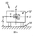
図1aを参照すると、車両12にロールオーバ検出システム10が搭載されている。車両12は、局所デカルト座標系で示してあり、X軸は前方を正とした車両の縦方向軸と一致し、またY軸は左方向を正とした車両の横方向軸と、Z軸は上向きを正とした車両の垂直軸と一致している。車両12の質量をMとすると、それに対応する重心CGは、地上からZ0の高さに位置している。図では車両12は、障害物14に向かってY軸負方向に、速度Uでスライドしている。
【0002】
図1bを参照すると、車両12の1つまたは複数の車輪16が障害物14と係合すると、そこから発生する反力Fによって、車両12はトリップポイント13に対してX軸回りに、時間変化する角速度ωx(t)で回転し、これによって時間変化する角度位置θ(t)を生じる。ここで関連する回転軸回りの車両12の慣性モーメントはIxであり、この回転軸はX軸と平行でトリップポイント13と交叉する。車両12の回転によって、重心CGの高さZCGは、障害物14との接触の以前の高さZ0に対して増大し、これによって車両12の位置エネルギ
【数1】
![]()
【数2】

【数3】
【0003】
図2を参照すると、ロールオーバ検出システム10は、横加速度計18と角速度センサ20を備え、これらは必要条件ではないが、車両12の重心CGに近接して装着するのが好ましい。横加速度計18は、局所Y軸に沿った、時間変化する横加速度成分Ay(t)に応答性を有する。例えば、横加速度計18は、少なくとも1軸の感度を有するマイクロマシン加工による加速度計など、局所Y軸に実質的に一致する1つの感度軸を有する加速度計でもよい。角速度センサ20、例えばジャイロスコープは、局所X軸回りの角速度の時間変化成分に応答性を有するように、方位が決められる。横加速度計18と角速度センサ20は、それぞれのフィルタ22、24に動作可能に接続され、それぞれの信号Ay(t)およびωx(t)を、メモリ28を有するプロセッサ26で処理するために、これらのフィルタでフィルタリングする。これらのフィルタ22、24は、当業者には知られているように、プロセッサ26と分離式にしても、組み込み式にしてもよく、またアナログ式でもデジタル式でも、あるいはその組合せでもよいことを理解すべきである。またフィルタ22、24はそれぞれの横加速度計18または角速度センサ20の部分となるように適合させてもよい。
【0004】
プロセッサ26は、それぞれのフィルタリングされた信号
【数4】
![]()
【0005】
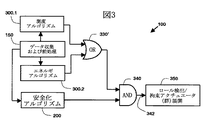
図3を参照すると、車両のロールオーバを検出して、例えば図2に示した装置によって、1つまたは複数の関連する安全拘束アクチュエータ30の作動を制御するロールオーバ検出アルゴリズム100の一実施態様には、データ収集および処理アルゴリズム150、測度アルゴリズム(measures algorithm)300.1、エネルギアルゴリズム300.2、安全化アルゴリズム200、およびそれに応じて安全拘束アクチュエータ(1つまたは複数)30の作動を制御する信号342を生成する、関連するロジック330’、340の組合せが含まれる。
測度アルゴリズム300.1は、ロールオーバ状態を検出するのに、経験則的な、時間域判別処理を使用しており、通常車両の大きな横方向作用力を伴い、比較的速い頭部接触時間(例えば<250msec)を特徴とする、ほとんどのロールオーバ事象に対して、展開時間を短縮する上で有利である。測度アルゴリズム300.1では、フィルタリングされた
【数5】
![]()
【数6】
![]()
【0006】
エネルギアルゴリズム300.2は、車両のロールオーバ発生過程に関する物理則に基づいて、位相空間判別処理を使用して、ロールオーバ状態を検出するものであり、主として車両の垂直方向力または車両12に対する低い横方向力によって生ずる低速のロール事象に対する信頼性のある展開判断をする上で有利である。エネルギアルゴリズム300.2は、フィルタリングされた角速度信号を利用して、車両12のロール状態を同定し、その瞬間的な全エネルギ(回転運動エネルギと位置エネルギ)と、関連する平衡点を超えて車両をロール回転させるのに要するエネルギとを比較する。エネルギアルゴリズム300.2は、関連する入口基準および出口基準に、フィルタリングされた
【数7】
![]()
【数8】
![]()
【0007】
図3には測度アルゴリズム300.1とエネルギアルゴリズム300.2とを組み合わせて使用する場合を示しているが、このことは本質的ではなく、いずれのアルゴリズムも単独で使用することもできることを理解すべきである。しかしながら、アルゴリズムを組み合わせることによって、関連するロールオーバ検出システム10のロバスト性を増大させることができる。この理由は、例えば「縁石走行(curb-trip)」状態のような状態においては、測度アルゴリズム300.1は、エネルギアルゴリズム300.2よりも迅速な判別を実施できるが、これに対して「螺旋状(corkscrew)」、「ランプ状(ramp)」、または「フリップ状(flip)」などのその他の状態においては、エネルギアルゴリズム300.2の方が、測度アルゴリズム300.1よりも迅速な判別が可能である。
測度アルゴリズム300.1およびエネルギアルゴリズム300.2は、互いに独立であるが両者とも、データ収集および処理アルゴリズム150からのフィルタリングされた共通のデータ、すなわちフィルタリングされた
【数9】
![]()
【数10】
![]()
【0008】
安全化アルゴリズム(safing algorithm)200は、1つまたは複数の対応する安全化拘束アクチュエータ30を展開可能にするために満たさなくてはならない、フィルタリングされた
【数11】
![]()
【数12】
![]()
【0009】
ロールオーバ検出アルゴリズム100の作動に際して、データ収集および処理アルゴリズム150からのデータに応じて、測度アルゴリズム300.1または(OR330’)エネルギアルゴリズム300.2が車両のロールオーバ状態を検出し、かつ(AND340)安全化アルゴリズム200が関連する独立の安全化条件が満たされると判断した場合、ステップ(350)において、車両12が実際にロールオーバするかしないにかかわらず、そのロールオーバ事象によって起こり得る関連する車両の乗員への傷害を軽減するために、1つまたは複数の安全拘束アクチュエータ30が展開される。
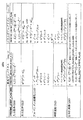
以下に図3〜7に示すフローチャートを参照して、データ収集および処理アルゴリズム150、安全化アルゴリズム200、測度アリゴリズム300.1およびエネルギアルゴリズム300.2について説明する。図6は、測度アルゴリズム300.1およびエネルギアルゴリズム300.2の両方の一般的なアルゴリズム構造のフローチャートを示しており、測度アルゴリズム300.1とエネルギアルゴリズム300.2の個々の詳細は図8a〜8cに表で示してある。アルゴリズムは数学的に記述してあり、応用例に特有の定数についてはパラメータを用いており、これらのパラメータを、特定の種類の車両について例となる数値とあわせて、図9aおよび9bに示してある。これらのパラメータは通常、例えば車両プラットフォームなどの特定の応用例に適合させるものであること、また図9aおよび9bに示すパラメータの具体的な数値は説明のためだけのものであり、本発明の範囲を限定するものと考えるべきではないことはいうまでもない。
【0010】
図4を参照すると、データ収集および処理アルゴリズム150は、ステップ(152)において横加速度計18から横加速度成分Ayの計測値を取得し、ステップ(158)において角速度センサ20から縦方向角速度ωxすなわちロール角速度の計測値を取得する。100回以上のロールオーバ試験のデータから、ロールオーバに伴う角速度ωxすなわちロール角速度は、一般に±300度/秒
【数13】
![]()
【数14】
![]()
【数15】
![]()
【数16】
![]()
【0011】
横加速度計18および角速度センサ20それぞれからの、横加速度成分Ayおよび角速度ωxの生データは、それぞれステップ(156)および(162)において、それぞれのフィルタ22、24によってフィルタリングされて、それぞれフィルタリングされた
【数17】
![]()
【数18】
![]()
【0012】
一般に、横加速度計18および角速度センサ20は、オフセットおよび/またはドリフト誤差(一般にセンサオフセット誤差と呼ばれる)を示す可能性があり、これを補償しない限り、関連するロール検出誤差が生じる可能性がある。このセンサオフセット誤差は、フィルタリングされた
【数19】
![]()
【数20】
![]()
【数21】
![]()
【数22】
![]()
【0013】
ステップ(164)から、フィルタリングされた
【数23】
![]()
【数24】
![]()
【0014】
図4では、角速度ωxの収集および処理の以前に、横加速度成分Axの収集および処理を示しているが、相対的な順序は逆になることもあり、またこれらの操作が並行して実行されることもあることを理解すべきである。
測度アルゴリズム300.1、エネルギアルゴリズム300.2、および安全化アルゴリズム200のそれぞれにおいては、対応するセンサオフセット、すなわち
【数25】
![]()
【数26】
![]()
【数27】
![]()
【数28】
![]()
【数29】
![]()
【0015】
図5を参照すると、安全化アルゴリズム200は、ステップ(202)から始まり、ここで関連する両フラグSAFING_EVENT_FLAGs(安全化イベントフラグ)、すなわちACCELERATION_SAFING_EVENT_FLAG(加速度安全化イベントフラグ) および ROLL_SAFING_EVENT_FLAG(ロール安全化イベントフラグ)が最初にリセットされる。次いで、ステップ(204)において、ONGOING_EVENT_FLAGsフラグ(すなわちONGOING_MEASURES_EVENT_FLAGまたはONGOING_ENERGY_EVENT_FLAG)のいずれかが設定されていることでわかるように、測度アルゴリズム300.1またはエネルギアルゴリズム300.2のいずれかが開始されている場合には、次のステップ(206)において、
【数30】
![]()
【数31】
![]()
【0016】
ステップ(208)に続いて、あるいはステップ(206)に続いて、ステップ(210)において、
【数32】
![]()
【数33】
![]()
【0017】
代替案として、安全化アルゴリズム200を、前記のフラグの1つだけと、関連する基準だけを組み込むように適合させることによって、安全化基準が、測度アルゴリズム300.1またはエネルギアルゴリズム300.2のいずれかの開始時刻に続く、第1ポイント時刻における第3の加速度閾値
【数34】
![]()
【数35】
![]()
【数36】
![]()
【数37】
![]()
【数38】
![]()
【数39】
![]()
【0018】
ロールオーバ検出システム10は、測度アルゴリズム300.1またはエネルギアルゴリズム300.2の実装用とは別個のマイクロプセッサを用いて安全化アルゴリズム200を実装することによって信頼性を改善するように適合させてもよく、この場合には安全化アルゴリズム200が進行イベントフラグONGOING_EVENT_FLAGsを認識しない場合には、これらのフラグに応じて安全化イベントフラグSAFING_EVENT_FLAGsをリセットするかわりに、1つまたは複数の安全化アクチュエータ30が展開されるまで、あるいは両アルゴリズムが終了してしまうことになるまで、安全化条件が作動状態に維持されるように、一方の安全化基準が最後に満たされた時刻から、ある遅延、例えば
【数40】
![]()
【0019】
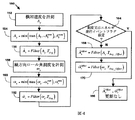
測度アルゴリズム300.1およびエネルギアルゴリズム300.2のそれぞれは、図6に示す全体アルゴリズム構造に従って作動し、これらのアルゴリズムはそれぞれ、すべて参照番号300で示してある。特定の参照番号に小数点番号をつけることによって、個別のアルゴリズムを参照することにする。例えば、一般的な全体処理は参照番号300で表し、測度アルゴリズムは300.1で、エネルギアルゴリズムは300.2で表す。別の例をあげると、全般のアルゴリズム計算ステップは参照番号326で表すが、参照番号326.1は測度アルゴリズム300.1のアルゴリズム計算ステップを特に表し、参照番号362.2はエネルギアルゴリズム300.2のアルゴリズム計算ステップを表す。特定のアルゴリズムステップに関連する特定の方程式は、各アルゴリズムについて、図8a〜8cに表形式で示し、関連するパラメータとその例としての値を、図9a、9bに表形式で示してある。
【0020】
図6を参照すると、全体ロール処理アルゴリズムはステップ(302)から開始され、対応する進行イベントフラグONGOING_EVENT_FLAGがリセットされる。このONGOING_EVENT_FLAGが設定されることは、ロール処理アルゴリズムの入口基準が満たされ、対応する出口基準は満たされず、したがって関連するアルゴリズムが作動状態であることを示す。次いでステップ(150)において、前述のデータ収集および処理アルゴリズム150に従って、このアルゴリズムで用いられる関連データが、収集かつ処理される。次いでステップ(304)において、ONGOING_EVENT_FLAGが設定されていない場合、つまり潜在的なロール事象からのデータを処理中ではなく、車両12にロール事象が生じていないことを示す場合には、ステップ(306)において1組の入口基準が評価されて関連する閾値と比較され、入口基準が満たされる場合には、ステップ(308)においてONGOING_EVENT_FLAGが設定され、かつステップ(310)において、例えばアルゴリズム関連する様々な動的変数を初期化することによって、アルゴリズムが開始される。
【0021】
あるいはステップ(304)から、進行イベントフラグONGOING_EVENT_FLAGが設定されており、潜在的なロール事象からのデータが処理中であることを示す場合には、ステップ(312)において、関連する時間の測度、例えばサンプル計数が更新されて、ステップ(400)で、新規に収集されたデータが評価されて、センサ(つまり横加速度計18または角速度センサ20)を再較正する必要があるかどうかが判断される。ステップ(400)に関連する処理を図7に示してあり、以下により詳細を説明する。
ステップ(400)から、1つ又は複数のセンサが再較正を必要とする場合、ステップ(314)において再較正を必要とする1つまたは複数のセンサが再較正される。例えば、横加速度計18および角速度センサ20の両方が試験可能であり、既知の刺激をセンサに与え、対応するセンサ出力が既知の刺激と一致するように較正することができる。例えば、横加速度計18が、マイクロマシン加工による、スプリング要素の梁で懸架されたマス要素を含むものであれば、マス要素とハウジングの間に静電場を印加して、基準加速度レベルに相当する量だけ梁を撓ませる。
【0022】
次いで、歪センシング要素からの出力が、基準加速度レベルに一致するように較正係数を計算する。ステップ(316)において、ステップ(314)の処理が、1つまたは複数のセンサが故障していることを示す場合、例えばセンサに試験刺激を加えるか否かにかかわらず、出力に実質的に変化がない場合には、ステップ(318)において、故障状態が設定され、警報装置、例えばライトが作動して車両12のドライバに警告し、ロールオーバ検出システムによる安全拘束アクチュエータ30の展開を不能とする。あるいはステップ(316)から、すなわち横加速度計18および角速度センサ20の両方ともが故障していない場合には、ステップ(320)において、両フラグONGOING_EVENT_FLAGs、すなわちONGOING_MEASURES_EVENT_FLAGおよびONGOING_ENERGY_EVENT_FLAGが、少なくとも1つのセンサの再較正が行われたことに応じてリセットされて、ステップ(150)から新たな処理が反復される。
【0023】
あるいはステップ(400)から、どのセンサも再較正の必要がない場合には、ステップ(322)において出口基準が評価されて、ステップ(306)における入口基準を再び満たしてアリゴリズムに再び入る時刻まで、アルゴリズムから退出するかどうかが決定される。ステップ(322)からは、出口基準が満たされる場合には、ステップ(324)においてアルゴリズムがエネルギアルゴリズム300.2であり、かつエネルギアルゴリズム300.2がステップ(306)で連続して登録され、かつ次いでタイムアウト
【数41】
![]()
【0024】
あるいは、ステップ(322)からは、アルゴリズムがステップ(306)で登録され、かつステップ(322)で退出していない場合に、ステップ(310)またはステップ(312)のいずれかからの時間測度の特定の値にしたがって、アルゴリズムの特定の反復について、関連するアルゴリズム計算が実施される。次いで、ステップ(330)において、関連するアルゴリズム検出基準が、アルゴリズムの特定の反復において満たされ、かつステップ(340)において安全化イベントフラグSAFING_EVENT_FLAG(s)、すなわちACCELERATION_SAFING_EVENT_FLAGおよび ROLL_SAFING_EVENT_FLAGが設定されている場合には、ステップ(350)においてロール事象が検出され、関連する安全拘束アクチュエータ30が作動される。逆に、ステップ(330)においてアルゴリズム検出基準が満たされない場合、またはステップ(340)において、すべての安全化イベントフラグが非設定であり、関連する安全化基準が、測度アルゴリズム300.1またはエネルギアルゴリズム300.2の実行中のある時刻において満たされない場合には、ステップ(150)から始まる次の反復が継続される。
【0025】
測度アルゴリズム300.1およびエネルギアルゴリズム300.2の両方とも、データ収集および処理アルゴリズム150からの横加速度成分Ayおよび縦方向角速度ωx の計測値に依存するが、各アルゴリズムに関連するその他の変数およびパラメータは互いに独立であり、同様にステップ(306)における関連する入口基準、ステップ(310)におけるアルゴリズム初期化、ステップ(322)における関連する出口基準、ステップ(326)におけるアルゴリズム計算、およびステップ(330)におけるアルゴリズム判断基準も独立であり、これらのすべてについての例を図8a,8b、8c、9a、および9bに詳細に示してある。例えば、各アルゴリズムは開始からの時間測度を決定し、縦方向角速度ωxの計測値を積分することによってロール角の測度を計算するが、それぞれのロール角の測度と同様に、これらのそれぞれの時間測度は互いに独立である。測度アルゴリズム300.1およびエネルギアルゴリズム300.2の両方とも、それぞれのアルゴリズムによる処理を開始するときに、初期には車両は水平である(すなわちθ(tentrance)=0)と仮定している。
【0026】
横方向加速度計18または角速度センサ20のいずれかが再較正を必要とするかどうかを判断する処理400を図7に示してある。ステップ(402)、(404)、(406)および(408)において、フィルタリングされた
【数42】
![]()
【数43】
![]()
【数44】
![]()
【数45】
![]()
【数46】
![]()
【数47】
![]()
【数48】
![]()
【数49】
![]()
【0027】
次に図6、図8a〜8c、および図9a,9bを参照して、測度アルゴリズム300.1についてより詳細に論じるが、図6のステップ番号は、その関連を示すために、ここでは「.1」のような添え字をつけてある。測度アルゴリズム300.1の進行イベントフラグONGOING_EVENT_FLAGは、進行測度イベントフラグONGOING_MEASURES_EVENT_FLAGと呼び、ステップ(306.1)で入口基準が満たされると、ステップ(308.1)で設定され、ステップ(322.1)で出口基準が満たされるとステップ(320.1)でリセットされる。進行測度イベントフラグONGOING_MEASURES_EVENT_FLAGは例えば、測度アルゴリズム300.1を実装するための、関連するプロセッサ26のメモリ28内の特定の場所に対応することもある。ステップ(322.1)に続いて、アルゴリズムに入るとその後は、ステップ(322.1)で測度アルゴリズム300.1の出口基準が満たされるか、またはロール事象が検出され安全拘束アクチュエータ30が展開されるまで、測度アルゴリズム300.1からは出ることはない。さらに、測度イベント出口基準が満たされて、測度アルゴリズム300.1から出た後は、測度アルゴリズム300.1は、関連する測度イベント入口基準がその後に満たされる場合には、再び入ることができる。
【0028】
ステップ(306.1)における、測度アルゴリズム300.1の入口基準は例えば、
【数50】
![]()
【数51】
![]()
【数52】
![]()
【0029】
ステップ(310.1)においては、ステップ(308.1)に続いて測度アルゴリズム300.1に最初に入ると、測度アルゴリズム300.1が初期化される。イベントサンプル数nMおよび角度位置の値θM(nM−1)および測度関数R(nM−1)が、例えばゼロ値に初期化される。またイベント入口時刻の直前のサンプル時刻tM(−1)が、現在時刻tに初期化された、測度イベント入口時刻tM(0)の値に初期化され、かつアルゴリズム入口からの時間間隔ΔtM(0)がゼロ値に初期化される。ここで用いた上添え字「M」は、ここでは測度アルゴリズム300.1に関連する変数を表す。
【0030】
測度アルゴリズム300.1の後続の反復時に、ステップ(304.1)において進行測度イベントフラグが設定され、次いでステップ(312.1)においてイベントサンプル数nMが増分され、関連する現行サンプル時刻
【数53】
![]()
【数54】
![]()
【数55】
![]()
【数56】
![]()
【数57】
![]()
【数58】
![]()
【数59】
![]()
【0031】
ステップ(322.1)において、出口基準が満たされない場合には、アルゴリズム計算はステップ(326.1)において測度アルゴリズム300.1の特定の反復に対して以下のように更新される。
最初に、補償された符号付の角速度値を積分することによって、角度位置θMが以下のように推定される。
【数60】
![]()
【数61】
![]()
【数62】
![]()
【数63】
![]()
【数64】
![]()
【数65】
![]()
次に測度関数Rが推定され、これは良度指数(figure-of-merit)FOMを計算するために用いられる。測度関数Rは以下のように求められる。
【数66】
【数67】
【数68】
![]()
【数69】
![]()
【0033】
測度関数Rの第1項に追加される残りの項は、3つの測度の積であり、それは力測度F*、回転運動エネルギ測度KE*、および位置エネルギ測度PE*である。力測度F*は、
【数70】
![]()
【数71】
![]()
【数72】
![]()
【数73】
![]()
【0034】
例えば
【数74】
![]()
【数75】
![]()
【数76】
![]()
【数77】
![]()
【数78】
![]()
【0035】
回転運動エネルギ測度PE*は、
【数79】
![]()
【数80】
![]()
【数81】
![]()
【数82】
![]()
【数83】
![]()
【0036】
力測度F*と回転運動エネルギ測度KE*の積は、
【数84】
![]()
【数85】
![]()
【数86】
![]()
【数87】
![]()
【0037】
位置エネルギ測度PE*は、定数と角度位置の現行サンプル
【数88】
![]()
【数89】
![]()
【数90】
![]()
【数91】
![]()
【0038】
良度指数FOMは次式で求められる。
【数92】
![]()
【数93】
![]()
【0039】
代替案として、特に比較的小さな
【数94】
![]()
【数95】
![]()
【0040】
しかし、このような理想的な性能が実現できない場合には、検出基準を適当な妥協手段となるように適合させることができる。例えば、重大なロール事象を十分迅速に、つまり関連する1つまたは複数の安全アクチュエータ30を、乗員への傷害を与えるリスクを軽減できるタイミングと速度で展開できるように、関連する頭部接触時間よりも十分に短い時間内に検出するためには、車両を完全にロールさせない(例えば縁石走行(curb trip)または中減速度型から高減速度型のロール事象)程度の重大ロールオーバ事象に応答して1つまたは複数の安全拘束アクチュエータ30が展開するのを許容することが必要なこともある。
【0041】
ステップ(330.1)の第1の検出条件として、測度イベント時間ΔtMが、測度イベント時間の範囲(ΔtM min、ΔtM max)内にあるか、どうかを以下のように試験する。
【数96】
![]()
【数97】
![]()
【数98】
![]()
【数99】
![]()
【0042】
観察された最速の頭部接触時間は、ロール事象の発生後、およそ115ミリ秒程度である。関連するデータ処理および安全拘束展開(例えばエアバッグ膨張)に約30ミリ秒を要すると仮定すると、これらの場合には、安全拘束アクチュエータ30は、ロール事象の開始後約90ミリ秒で完全に展開されることになる。最小起動時間Δtminは、横加速度計18および角速度センサ20からの信号がもたらす情報をできる限り利用しつつ、一方で重大事象における頭部接触を回避するのに、時間余裕をもって展開判断が行えるようにする。最大起動時間Δtmaxは、ロール判別アルゴリズムの連鎖事象に対する脆弱性を低減し、また時間間隔のあいた2つの横方向事象の2番目の事象によってロールオーバが引き起こされる事故において、ロール判別アルゴリズムをリセットし、ロールオーバの第2の「実際の」開始事象を検知することを可能にする。ステップ(330.1)において、測度イベント時間ΔtMが指定された範囲内にある場合には、第1の検出条件は満たされ、追加の検出基準がステップ(330.1)で評価される。そうでない場合には、処理はステップ(150)から次の反復が継続される。
【0043】
ステップ(330.1)の第2に検出条件として、例としての車両プラットフォームについて、上述の検出戦略にしがって必要な実質的にすべての事象に対して、良度指数FOMと、十分に迅速な判別時間をもたらす閾値関数
【数100】
![]()
【数101】
![]()
【数102】
![]()
【数103】
![]()
【数104】
![]()
【0044】
一般に、異なる型式の車両は、閾値関数
【数105】
![]()
【数106】
![]()
【数107】
![]()
【数108】
![]()
【数109】
![]()
【0045】
ステップ(330.1)の第3の検出条件として、安全拘束アクチュエータ30の予期される展開時において、良度指数FOMの絶対値が、時間に対して増大しているかどうかを、以下のように試験する。
【数110】
![]()
【0046】
ステップ(330.1)の第4の検出条件として、安全拘束アクチュエータ30の予測される展開時における補償横加速度成分
【数111】
![]()
【数112】
![]()
【数113】
【数114】
![]()
【数115】
![]()
【数116】
![]()
【数117】
![]()
【0047】
ステップ(330.1)の第5の検出条件として、
【数118】
![]()
【数119】
![]()
【数120】
![]()
【数121】
![]()
【数122】
![]()
【数123】
![]()
【0048】
ここで記述する測度アルゴリズム300.1は、一連の車両ロールオーバ試験のデータを用いた試験に合格しており、最終的な車両のロールオーバを高い信頼性で予測できることが実証されている。大きな横加速度によって生じるロール事象については、比較的迅速に予測をすることができ、これによって測度アルゴリズム300.1が、頭部接触が通常最も迅速に発生するタイプのロールオーバに対して、頭部接触以前にエアバッグを展開することが可能となる。一般に、測度アルゴリズム300.1は、縁石走行や高g型横方向減速事象に類似する、短時間および中程度時間のロール事象に対して、比較的早期のロールオーバ検出と、関連する安全拘束アクチュエータ(群)30の比較的早期の起動時間(TTF)を実現する上で利点がある。
【0049】
したがって、測度アルゴリズム300.1を組み入れたロールオーバ検出システム10は、以下のステップにより、偶発的な展開を最小化しながら、乗員の頭部接触時間に適合するロールオーバエアバッグの展開時間を可能にする車両のロールオーバの改良型識別法を実現する。
それは、計測された横加速度を用いて将来(20〜30ミリ秒後)のロール運動を予測すること、
横加速度に、角速度および全回転角を組み合わせて、開始角度が水平から約20度未満であるロール事象について、車両の初期角度情報を必要とすることなく、現行回転状態および運動と、回転を生成している強制関数との測度を生成すること、
車両特有の動的特性(ロールオーバ試験データから抽出される)に初期の車両応答測定値を組み合わせて利用して、最終的なロールオーバの発生を、そのような事象が明白になる以前に予測すること、である。
【0050】
図10を参照すると、テストA,テストB、テストCおよびテストDと名づけた4つの異なる試験条件を、測度アルゴリズム300.1とエネルギアルゴリズム300.2を説明かつ比較する目的で表にして示してある(エネルギアルゴリズム300.2については以下にさらに詳細に述べる)。テストAおよびテストBは、螺旋状テストであり、これはエネルギアルゴリズム300.2が、測度アルゴリズム300.1よりも迅速なロールオーバ検出を示す条件を示しており、テストCおよびDは減速スレッドテストであり、これらについては測度アルゴリズム300.1がエネルギアルゴリズム300.2よりも迅速なロールオーバ検出を示す。テストAおよびDにおいては、車両はロールオーバを起こしたが、テストBおよびCにおいては、ロールオーバは起こさず、最大ロール角が、それぞれ37度および34度であった。初期車両速度、平均車両減速度、関連する検出およびイベント時間も、図10に表示してあり、ここで頭部接触時間は乗員(ダミー)の頭部が車両の内装に実際に衝突した時間である。
【0051】
図11a〜11dを参照すると、テストA〜Dについて図10に表示した条件にしたがい、加速度センサ20からのフィルタリングされたロール速度(角速度)、ロール角、および横加速度計18からのフィルタリングされた横加速度を、それぞれ時間の関数として示してある。
図12を参照すると、テストCおよびDについて計算で求めた良度指数を、測度イベント時間ΔtM、すなわち図10の表に示した特定の型式の車両についての実際のスレッド減速テストにおける、測度アルゴリズム300.1の開始からの時間の関数としてプロットしてある。図12には、この特定の形式の車両についての、関連する閾値関数
【数124】
![]()
【0052】
ここで記述する測度アルゴリズム300.1とによって計算した良度指数
【数125】
![]()
【数126】
![]()
【0053】
図6、図8a〜c、および図9a,9bを参照して、エネルギアルゴリズム300.2についてより詳細に述べるが、ここで図6のステップは、「.2」という添え字をつけて、それに関連することを示している。エネルギアルゴリズムについての、進行イベントフラグONGOING_EVENT_FLAGは、ONGOING_ENERGY_EVENT_FLAGと呼び、ステップ(306.2)における入口基準が満たされると、ステップ(308.2)において設定され、ステップ(322.2)において出口基準が満たされるとステップ(320.2)においてリセットされる。例えば、ONGOING_ENERGY_EVENT_FLAGは、エネルギアルゴリズム300.2を実装する関連するプロセッサ26のメモリ28の特定の場所に対応させてもよい。ステップ(306.2)に続いて、エネルギアルゴリズム300.2に入った後は、ステップ(322.2)においてエネルギイベント出口基準が満たされるか、ロール事象300.2が検出されて、安全拘束アクチュエータ30が展開されるまでは、そこから出ない。さらに、エネルギイベント出口基準が満たされて、エネルギアルゴリズム300.2から出た後に、その後関連するエネルギイベント入口基準が満たされれば、エネルギアルゴリズム300.2に再び入ることができる。
【0054】
エネルギアルゴリズム300.2は、角速度センサ20からの角速度ωx信号を利用し、車両のロール状態を同定し、車両12の全体エネルギ(回転運動および位置エネルギ)と完全にロールを生じさせるのに必要なエネルギとを比較する。
ステップ(306.2)において、エネルギアルゴリズム300.2の入口基準は、例えば
【数127】
![]()
【数128】
![]()
【数129】
![]()
【数130】
![]()
【数131】
![]()
【数132】
![]()
【数133】
![]()
【0055】
ステップ(310.2)において、ステップ(306.1)に続いて最初にエネルギアルゴリズム300.2に入場すると、エネルギアルゴリズム300.2が初期化される。イベントサンプル数nEおよび角度位置の値
【数134】
![]()
【数135】
![]()
【数136】
![]()
【数137】
![]()
【数138】
![]()
【数139】
![]()
【0056】
後続のエネルギアルゴリズム300.2の反復時に、ステップ(304.2)において、ONGOING_ENERGY_EVENT_FLAGが設定されている場合には、ステップ(312.2)において、イベントサンプル数nEが増分され、関連する現行のサンプル時刻
【数140】
![]()
【数141】
![]()
【数142】
![]()
【数143】
![]()
【数144】
![]()
【数145】
![]()
【数146】
![]()
【数147】
![]()
【数148】
![]()
【数149】
![]()
【数150】
![]()
【数151】
![]()
エネルギアルゴリズム300.2は、比較的遅いロールオーバ事象が発生する可能性があるために、測度アルゴリズム300.1よりも、リスタートさせるまでに(すなわちアルゴリズムから出てリセットされるまでに)実質的に長い時間を必要とする。特定の型式の車両の例においては、実際のロールオーバデータに基づいて、時間間隔閾値
【数152】
![]()
【数153】
![]()
【数154】
![]()
【0058】
ステップ(322.2)において、出口基準が満たされない場合には、アルゴリズム計算は、エネルギアルゴリズム300.2の特定の反復について、ステップ(326.2)で以下のように更新される。
最初に、角度位置
【数155】
![]()
【数156】
![]()
【数157】
![]()
【数158】
![]()
【数159】
![]()
【数160】
![]()
【数161】
![]()
【数162】
![]()
ステップ(326.2)において、アルゴリズム計算は、ジャイロスコープ誤差または重大な車両運動の結果によるオフセットのいずれかによる、角速度ωx信号のオフセットを補償するように適合されており、そうしない場合には、特に角速度が実質的に振動挙動を示す可能性のあるラフ路面状態に対しては、これらのオフセットが、
【数163】
![]()
【数164】
![]()
【数165】
![]()
【数166】
![]()
【0060】
例えば、図13を参照すると、真の角速度オフセット
【数167】
![]()
【数168】
![]()
【数169】
![]()
【数170】
![]()
【数171】
![]()
【数172】
【数173】
![]()
【数174】
![]()
【数175】
![]()
【数176】
![]()
【0061】
図14を参照すると、ロール振動効果に対する上記の補償の効果を示してあり、ここでは、図13にプロットされた角速度データから積分したロール角を、様々な条件について時間の関数として示してある。第1の条件として、真の角速度オフセット
【数177】
![]()
【数178】
![]()
【数179】
![]()
【0062】
ステップ(326.2)において、アルゴリズムの計算によって、ステップ(306.2)の入口基準が満たされる最近時間の記録がさらに与えられ、これによってステップ(322.2)の出口基準の補助的な基礎が、以下のように与えられる。
【数180】
![]()
【0063】
エネルギアルゴリズム300.2の主要検出基準は、角速度とロール角の関連する位相空間(すなわちω‐θ位相空間)における、
【数181】
![]()
【数182】
![]()
剛体運動力学に従って、関連する剛体のロール事象と非ロール事象を判別する位相空間内の理論的閾値境界が存在する。例えば、この理論的閾値境界は次式で求められる。
【数183】
【0064】
しかし、非剛体効果のために、実際の閾値境界は、通常上記の理論閾値境界に沿った約5つまたは6つの連結線分からなる、区分線形境界としてモデル化するのが有利であるが、これをロール事象と非ロール事象の識別性能を改善するために特定の車両12または車両プラットフォームについて適合させてもよい。一般に、この境界は位相空間内の関数(例えば、ロール角θの関数)、位相空間内の区分関数(例えばロール角θの区分関数)、または位相空間でのテーブルルックアップのいずれかで表すことができる。
図15を参照すると、上述の移動平均フィルタを用いてフィルタリングした、実際のロールオーバテストデータを、図11aおよび11bに示すテストAおよびBそれぞれについて、図10の条件に従い、関連する理論的な閾値境界の例および実際の区分線形閾値境界の例と共に、ω‐θ位相空間内にプロットしてある。
【0065】
現行順序の組
【数184】
![]()
【数185】
![]()
【数186】
![]()
【数187】
![]()
【数188】
【0066】
ω‐θ位相空間における
【数189】
![]()
【数190】
【数191】
【数192】
![]()
【数193】
![]()
【数194】
【数195】
![]()
【数196】
エネルギ検出基準が、ステップ(330.2)で満足され、かつステップ(340)において、安全化基準が満たされる場合には、ステップ(350)において、関連する1人または複数の乗員への傷害が軽減するために、関連する1つまたは複数の安全拘束アクチュエータ30が展開される。エネルギアルゴリズム300.2の検出基準が満たされるときまでに安全化基準が満たされない場合には、安全化基準が満たされるか、またはステップ(322.2)でエネルギアルゴリズム300.2から出るかのいずれかになるまで、エネルギアルゴリズム300.2が反復されるように、エネルギアルゴリズム300.2の展開決定はラッチされない。
【0067】
測度アルゴリズム300.1およびエネルギアルゴリズム300.2は、共通のプロセッサ26上または別個のプロセッサ26上で、直列にでも、並列にでも実行することが可能であることはいうまでもない。直列に実行される場合には、図6に示す1回の反復についてのステップは、一方のアルゴリズムについて完了し、次いで他方のアルゴリズムが、第1のパスに対してステップ(302)から、または後続のパスに対してステップ(150)から開始されることになる。
ロールオーバ検出アルゴリズムは、特定の形式の式によって表されていたが、これらの計算は、本願の教示の範囲を逸脱することなく、様々な方法で、特定のプロセッサ26上に実装できることはいうまでもない。例えば、本願に記載の特定の計算を、特定のプロセッサに実際に実装するためには、例えば関連するアナログ/デジタル変換器の解像度や、特定のプロセッサ26によって実行可能な数学処理の形式と精度、また特定のプロセッサ26のワード長などに応じて、修正を必要とする可能性がある。
【0068】
ロール判別アルゴリズムは、本願ではサンプリングされたデータに対して適用すると説明したが、アルゴリズムは、例えばアナログプロセッサを用いて、連続的に実装することも可能であることはいうまでもない。さらに、イベントサンプル数nMは、ロール判別の実際の実装においては、明示式および暗示式のどちらでもよく、また関連する時間依存の変数は、時間tの関数、またはイベントサンプル数nM、nEの関数の、いずれでも表すことができることも理解すべきである。
測度アルゴリズム300.1およびエネルギアルゴリズム300.2は、関連する
【数197】
![]()
【0069】
本願記載のロール判別アルゴリズムは、関連するテストデータから導いており、そのためにパラメータを抽出した車両とは異なる、他の種類の車両に適用する場合には、調節を必要とする可能性があり、この調節の基準は、例えば、ロールオーバ事象をロバストに、かつ早期に検出することであり、同時にまた可能な程度に、非ロールオーバ事象をロールオーバ事象として誤判別することを避けることである。
本願に記載した様々なパラメータについての特定の値は、それに限定するものではなく、例えばロールオーバの発生しやすさが異なる、異なる型式の車両に対して異なってもよい。例えば、比較的重心の高い車両、または比較的ホイールベースの狭い車両、例えばスポーツユーティリティビークルなどは、比較的重心の低い、またはホイールベースの広い、例えば乗用セダンよりも、ロールオーバを発生しやすい。
さらに、ロールオーバ検出システム10は、関連の縦方向加速度計およびピッチ角速度センサを備えることによって、ピッチオーバ事象、すなわち車両の局所Y軸回りの事象を検知するように適合させることも可能である。
【0070】
特定の実施態様について詳細を説明したが、当業者であれば、本開示の全般的な教示を参考として、これらの詳細に対する、様々な修正態様および代替手法を開発することが可能であることを理解するであろう。したがって、開示した特定の配設は、説明だけを目的とするものであり、本発明の範囲を限定するものではなく、本発明は添付の特許請求の範囲およびそのすべての等価物の全範囲を授与されるべきである。
【図面の簡単な説明】
【図1a】ロール発生開始以前の車両の背面図である。
【図1b】ロール発生中の車両の背面図である。
【図2】ロールオーバ検出システムを示すブロック図である。
【図3】ロールオーバ検出アルゴリズムを示すフロー図である。
【図4】ロールオーバ検出アルゴリズムに組み込まれたデータ収集および処理アルゴリズムを示すフロー図である。
【図5】ロールオーバ検出アルゴリズムに組み込まれた安全化アルゴリズムを示すフロー図である。
【図6】ロールオーバ検出アルゴリズムを示すフロー図である。
【図7】ロールオーバ検出アルゴリズムに組み込まれた、センサ再較正が必要かどうかを判断するためのアルゴリズムを示すフロー図である。
【図8a】ロールオーバ検出アルゴリズムの詳細を示す表である。
【図8b】ロールオーバ検出アルゴリズムの詳細を示す表である。
【図8c】ロールオーバ検出アルゴリズムの詳細を示す表である。
【図9a】ロールオーバ検出アルゴリズムのパラメータ値の例を示す表である。
【図9b】ロールオーバ検出アルゴリズムのパラメータ値の例を示す表である。
【図10】様々なロールオーバ事象および非ロールオーバ事象に関連する条件を示す表である。
【図11a】ロールオーバ事象が発生する、テストAと名づけた螺旋状(corkskrew)ロールオーバテストを受けた車両の、フィルタリングされたロール角速度、ロール角、およびフィルタリングされた横加速度のグラフである。
【図11b】ロールオーバ事象は発生しない、テストBと名づけた螺旋状ロールオーバテストを受けた車両の、フィルタリングされたロール角速度、ロール角、およびフィルタリングされた横加速度のグラフである。
【図11c】 ロールオーバ事象は発生しない、テストCと名づけた減速スレッドテストを受けた車両の、フィルタリングされたロール角速度、ロール角、およびフィルタリングされた横加速度のグラフである。
【図11d】ロールオーバ事象が発生する、テストDと名づけた減速スレッドテストを受けた車両の、フィルタリングされたロール角速度、ロール角、およびフィルタリングされた横加速度のグラフである。
【図12】テストDのロールオーバ事象およびテストCの非ロールオーバ事象について、測度アルゴリズムに応じた、ロールオーバ測度の良度指数および関連する展開閾値を時間の関数として示すグラフである。
【図13】ロール角速度オフセットを含む信号について、ロール角速度を時間の関数として示すグラフである。
【図14】ロール角速度からロール角を同定する、関連する様々な処理について、図13のデータに基づいてロール角を時間の関数として示すグラフである。
【図15】テストAのロールオーバ事象およびテストBの非ロールオーバ事象について、エネルギアルゴリズムに従って、ロール角の関数としてのロール角速度と、関連するロールオーバ閾値とを示すグラフである。[0001]
When a vehicle rollover occurs, especially in a type of rollover with a relatively short head closure time, before the head first contacts the vehicle interior, for example, a seat belt pretensioner, air There is a need for a vehicle rollover detection system that allows vehicle rollover discrimination with time to deploy an associated safety restraint actuator such as a bag or roll curtain. For example, depending on the rollover event, a head contact may occur before it can be reliably determined from the physical laws of the roll rotation event whether the vehicle will roll over completely. There is also a need for a robust vehicle rollover detection system that determines vehicle rollover sufficiently quickly depending on whether the rollover is a relatively slow or relatively fast event.
Referring to FIG. 1 a, a
[0002]
Referring to FIG. 1 b, when one or more wheels 16 of the
[Expression 1]
![]()
[Expression 2]
[Equation 3]
[0003]
Referring to FIG. 2, the
[0004]
The
[Expression 4]
![]()
[0005]
Referring to FIG. 3, an embodiment of a
The measure algorithm 300.1 uses an empirical time domain discrimination process to detect the rollover condition, usually with a large lateral force of the vehicle, and a relatively fast head contact time ( For most rollover events characterized by <250 msec), for example, it is advantageous in reducing deployment time. In measure algorithm 300.1, filtered
[Equation 5]
![]()
[Formula 6]
![]()
[0006]
The energy algorithm 300.2 detects a rollover state using a phase space discriminating process based on a physical rule relating to a vehicle rollover occurrence process, and is mainly low in the vehicle vertical force or the
[Expression 7]
![]()
[Equation 8]
![]()
[0007]
Although FIG. 3 shows a combination of the measure algorithm 300.1 and the energy algorithm 300.2, this is not essential and it is understood that either algorithm can be used alone. Should. However, combining the algorithms can increase the robustness of the associated
The measure algorithm 300.1 and energy algorithm 300.2 are independent of each other, but both are filtered common data from the data collection and
[Equation 9]
![]()
[Expression 10]
![]()
[0008]
The
[Expression 11]
![]()
[Expression 12]
![]()
[0009]
In operation of
The data collection and
[0010]
Referring to FIG. 4, the data collection and
[Formula 13]
![]()
[Expression 14]
![]()
[Expression 15]
![]()
[Expression 16]
![]()
[0011]
Lateral acceleration component A from each of the
[Expression 17]
![]()
[Expression 18]
![]()
[0012]
In general, the
[Equation 19]
![]()
[Expression 20]
![]()
[Expression 21]
![]()
[Expression 22]
![]()
[0013]
Filtered from step (164)
[Expression 23]
![]()
[Expression 24]
![]()
[0014]
In FIG. 4, the angular velocity ωxBefore the collection and processing of the lateral acceleration component AxHowever, it should be understood that the relative order may be reversed and that these operations may be performed in parallel.
In each of the measure algorithm 300.1, energy algorithm 300.2, and
[Expression 25]
![]()
[Equation 26]
![]()
[Expression 27]
![]()
[Expression 28]
![]()
[Expression 29]
![]()
[0015]
Referring to FIG. 5, the
[30]
![]()
[31]
![]()
[0016]
Following step (208) or following step (206), at step (210),
[Expression 32]
![]()
[Expression 33]
![]()
[0017]
As an alternative, by adapting the
[Expression 34]
![]()
[Expression 35]
![]()
[Expression 36]
![]()
[Expression 37]
![]()
[Formula 38]
![]()
[39]
![]()
[0018]
The
[Formula 40]
![]()
[0019]
Each of the measure algorithm 300.1 and the energy algorithm 300.2 operates according to the overall algorithm structure shown in FIG. 6, and each of these algorithms is designated by the
[0020]
Referring to FIG. 6, the entire roll processing algorithm starts from step (302), and the corresponding progress event flag ONOING_EVENT_FLAG is reset. Setting this ONGOING_EVENT_FLAG indicates that the entry criterion of the roll processing algorithm is satisfied, the corresponding exit criterion is not satisfied, and therefore the associated algorithm is active. Then in step (150), according to the data collection and
[0021]
Alternatively, from step (304), if the progress event flag ONGOING_EVENT_FLAG is set to indicate that data from a potential roll event is being processed, then in step (312) the associated time measure, eg The sample count is updated and in step (400) the newly collected data is evaluated to determine if the sensor (ie
From step (400), if one or more sensors require recalibration, in step (314), the one or more sensors that require recalibration are recalibrated. For example, both the
[0022]
A calibration factor is then calculated so that the output from the strain sensing element matches the reference acceleration level. In step (316), if the process of step (314) indicates that one or more sensors are faulty, for example, whether or not a test stimulus is applied to the sensors, the output is substantially changed. If not, in step (318) a fault condition is set and an alarm device, for example a light, is activated to alert the driver of the
[0023]
Alternatively, from step (400), if no sensors need to be recalibrated, the exit criteria are evaluated in step (322) until the time when the entrance criteria in step (306) are re-filled and the algorithm is re-entered. It is determined whether to exit the algorithm. From step (322), if the exit criteria are met, in step (324) the algorithm is energy algorithm 300.2, and energy algorithm 300.2 is continuously registered in step (306), and Then timeout
[Expression 41]
![]()
[0024]
Alternatively, from step (322), the time measure from either step (310) or step (312) is specified if the algorithm was registered at step (306) and not exited at step (322). Depending on the value of, the associated algorithm calculation is performed for a particular iteration of the algorithm. Then, in step (330), if the relevant algorithm detection criteria are met in a particular iteration of the algorithm and the safety event flag SAFING_EVENT_FLAG (s), ie ACCELERATION_SAFING_EVENT_FLAG and ROLL_SAFING_EVENT_FLAG, is set in step (340) In step (350), a roll event is detected and the associated
[0025]
Both the measure algorithm 300.1 and the energy algorithm 300.2 both have a lateral acceleration component A from the data collection and processing algorithm 150.yAnd longitudinal angular velocity ωx The other variables and parameters associated with each algorithm are independent of each other, as well as the relevant entry criteria in step (306), algorithm initialization in step (310), and in step (322). The associated exit criteria, algorithm calculations in step (326), and algorithm criteria in step (330) are also independent, examples of all of which are shown in detail in FIGS. 8a, 8b, 8c, 9a, and 9b. is there. For example, each algorithm determines a time measure from the start, and the longitudinal angular velocity ωxThe roll angle measure is calculated by integrating the measured values of each of these, as with each roll angle measure, each of these time measures being independent of each other. In both measure algorithm 300.1 and energy algorithm 300.2, the vehicle is initially horizontal (ie, θ (tentrance) = 0).
[0026]
A
[Expression 42]
![]()
[Expression 43]
![]()
(44)
![]()
[Equation 45]
![]()
[Equation 46]
![]()
[Equation 47]
![]()
[Formula 48]
![]()
[Equation 49]
![]()
[0027]
The measure algorithm 300.1 will now be discussed in more detail with reference to FIGS. 6, 8a-8c, and FIGS. 9a, 9b, but the step numbers in FIG. A subscript such as “1” is attached. The progress event flag ONGOING_EVENT_FLAG of the measure algorithm 300.1 is called the progress measure event flag ONGOING_MEASURES_EVENT_FLAG. When the entrance criterion is satisfied in step (306.1), it is set in step (308.1), and step (322.1). If the exit criterion is satisfied in step (320.1), it is reset. The progress measure event flag ONGOING_MEASURES_EVENT_FLAG may correspond to a particular location in the
[0028]
The entry criterion of the measure algorithm 300.1 in step (306.1) is, for example:
[Equation 50]
![]()
[Equation 51]
![]()
[Formula 52]
![]()
[0029]
In step (310.1), when the measure algorithm 300.1 is first entered following step (308.1), the measure algorithm 300.1 is initialized. Number of event samples nMAnd angle position value θM(NM-1) and the measure function R (nM-1) is initialized to a zero value, for example. Also, the sample time t just before the event entrance timeM(-1) is a measure event entry time t initialized at the current time tMInitialized to a value of (0) and the time interval Δt from the algorithm entryM(0) is initialized to zero value. The superscript “M” used here represents a variable related to the measure algorithm 300.1.
[0030]
On subsequent iterations of measure algorithm 300.1, the progress measure event flag is set in step (304.1), and then in step (312.1) the number of event samples nMIs incremented and the associated current sample time
[Equation 53]
![]()
[Formula 54]
![]()
[Expression 55]
![]()
[56]
![]()
[Equation 57]
![]()
[Formula 58]
![]()
[Formula 59]
![]()
[0031]
In step (322.1), if the exit criteria are not met, the algorithm calculation is updated in step (326.1) for a particular iteration of measure algorithm 300.1 as follows.
First, the angular position θ is integrated by integrating the compensated signed angular velocity value.MIs estimated as follows.
[Expression 60]
![]()
[Equation 61]
![]()
[62]
![]()
[Equation 63]
![]()
[Expression 64]
![]()
[Equation 65]
![]()
A measure function R is then estimated, which is used to calculate a figure-of-merit FOM. The measure function R is obtained as follows.
[Equation 66]
[Expression 67]
[Equation 68]
![]()
[Equation 69]
![]()
[0033]
The remaining term added to the first term of the measure function R is the product of the three measures, which is the force measure F*, Rotational kinetic energy measure KE*, And potential energy measure PE*It is. Force measure F*Is
[Equation 70]
![]()
[Equation 71]
![]()
[Equation 72]
![]()
[Equation 73]
![]()
[0034]
For example
[Equation 74]
![]()
[Expression 75]
![]()
[76]
![]()
[77]
![]()
[Formula 78]
![]()
[0035]
Rotational kinetic energy measure PE*Is
[79]
![]()
[80]
![]()
[Formula 81]
![]()
[Formula 82]
![]()
[Formula 83]
![]()
[0036]
Force measure F*Rotational kinetic energy measure KE*The product of
[Expression 84]
![]()
[Expression 85]
![]()
[86]
![]()
[Expression 87]
![]()
[0037]
Potential energy measure PE*Is the current sample of constant and angular position
[Equation 88]
![]()
[Expression 89]
![]()
[90]
![]()
[91]
![]()
[0038]
The goodness index FOM is obtained by the following equation.
[Equation 92]
![]()
[Equation 93]
![]()
[0039]
As an alternative, especially relatively small
[Equation 94]
![]()
[95]
![]()
[0040]
However, if such ideal performance cannot be achieved, the detection criteria can be adapted to be an appropriate compromise. For example, more than a related head contact time so that a significant roll event can be deployed quickly enough, that is, the associated
[0041]
As the first detection condition of step (330.1), measure event time ΔtMIs the measure event time range (ΔtM min, ΔtM max) Is tested as follows.
[Equation 96]
![]()
[Equation 97]
![]()
[Equation 98]
![]()
[99]
![]()
[0042]
The fastest head contact time observed is on the order of 115 milliseconds after the occurrence of a roll event. Assuming that the associated data processing and safety restraint deployment (eg, airbag inflation) takes about 30 milliseconds, in these cases, the
[0043]
As a second detection condition in step (330.1), for the example vehicle platform, a goodness index FOM and sufficiently fast for substantially all events required by the above detection strategy. Threshold function that yields accurate discrimination time
[Expression 100]
![]()
## EQU1 ##
![]()
## EQU10 ##
![]()
[Formula 103]
![]()
[Formula 104]
![]()
[0044]
In general, different types of vehicles have a threshold function
[Formula 105]
![]()
[Formula 106]
![]()
[Expression 107]
![]()
[Formula 108]
![]()
[Formula 109]
![]()
[0045]
As a third detection condition of step (330.1), whether or not the absolute value of the goodness index FOM increases with time at the expected deployment of the
## EQU1 ##
![]()
[0046]
As a fourth detection condition of step (330.1), a compensated lateral acceleration component at the time of predicted deployment of the
[Formula 111]
![]()
## EQU1 ##
![]()
[Formula 113]
[Formula 114]
![]()
[Expression 115]
![]()
[Formula 116]
![]()
[Expression 117]
![]()
[0047]
As the fifth detection condition of step (330.1),
[Formula 118]
![]()
[Formula 119]
![]()
[Expression 120]
![]()
[Equation 121]
![]()
[Equation 122]
![]()
[Formula 123]
![]()
[0048]
The measure algorithm 300.1 described here has passed tests using a series of vehicle rollover test data and has proven to be able to reliably predict the final vehicle rollover. Roll events caused by large lateral accelerations can be predicted relatively quickly so that the measure algorithm 300.1 can be used for the type of rollover where head contact usually occurs most quickly. The airbag can be deployed before contact. In general, measure algorithm 300.1 includes relatively early rollover detection and associated safety restraint actuators for short and medium time roll events, similar to curb travel and high g lateral deceleration events. There is an advantage in realizing the relatively early start-up time (TTF) of (group) 30.
[0049]
Thus, the
It uses the measured lateral acceleration to predict the future (after 20-30 milliseconds) roll motion,
Combines lateral acceleration with angular velocity and full rotation angle to generate current rotation state and motion and rotation for roll events where the starting angle is less than about 20 degrees from horizontal without requiring initial vehicle angle information Generating a measure with a coercive function
Use vehicle-specific dynamic characteristics (extracted from rollover test data) in combination with initial vehicle response measurements to predict the eventual rollover before such events become apparent It is to be.
[0050]
Referring to FIG. 10, four different test conditions, named Test A, Test B, Test C, and Test D, are tabulated for purposes of explaining and comparing the measure algorithm 300.1 and the energy algorithm 300.2. (Energy algorithm 300.2 is described in further detail below). Test A and Test B are spiral tests, which show that the energy algorithm 300.2 shows a faster rollover detection than the measure algorithm 300.1, and tests C and D are the deceleration thread test For these, the measure algorithm 300.1 shows faster rollover detection than the energy algorithm 300.2. In tests A and D, the vehicle rolled over, but in tests B and C, no rollover occurred and the maximum roll angles were 37 degrees and 34 degrees, respectively. The initial vehicle speed, average vehicle deceleration, associated detection and event times are also shown in FIG. 10, where the head contact time is the time when the head of the occupant (dummy) actually hits the interior of the vehicle is there.
[0051]
Referring to FIGS. 11a-11d, filtered roll speed (angular velocity) from
Referring to FIG. 12, the merit index obtained by calculation for tests C and D is expressed as measure event time Δt.MThat is, it is plotted as a function of time from the start of the measure algorithm 300.1 in an actual thread deceleration test for the particular type of vehicle shown in the table of FIG. FIG. 12 shows the associated threshold function for this particular type of vehicle.
[Expression 124]
![]()
[0052]
Merit index calculated by the measure algorithm 300.1 described here
[Expression 125]
![]()
[Expression 126]
![]()
[0053]
The energy algorithm 300.2 is described in more detail with reference to FIGS. 6, 8a-c, and 9a, 9b, where the step of FIG. It is related. The progress event flag ONGOING_EVENT_FLAG for the energy algorithm is called ONGOING_ENERGY_EVENT_FLAG and is set in step (308.2) when the entry criterion in step (306.2) is met, and the exit criterion is met in step (322.2). Is reset in step (320.2). For example, ONGOING_ENERGY_EVENT_FLAG may correspond to a particular location in the
[0054]
The energy algorithm 300.2 is an angular velocity ω from the angular velocity sensor 20.xThe signal is used to identify the roll condition of the vehicle and to compare the overall energy of the vehicle 12 (rotational motion and potential energy) with the energy required to completely roll.
In step (306.2), the entrance criterion of the energy algorithm 300.2 is, for example,
[Expression 127]
![]()
[Expression 128]
![]()
[Expression 129]
![]()
[Expression 130]
![]()
[Equation 131]
![]()
[Expression 132]
![]()
[Formula 133]
![]()
[0055]
In step (310.2), when entering energy algorithm 300.2 for the first time following step (306.1), energy algorithm 300.2 is initialized. Number of event samples nEAnd angular position values
[Formula 134]
![]()
[Expression 135]
![]()
[Formula 136]
![]()
[Expression 137]
![]()
[Formula 138]
![]()
[Formula 139]
![]()
[0056]
When ONGOING_ENERGY_EVENT_FLAG is set in step (304.2) during the subsequent iteration of energy algorithm 300.2, the number of event samples n in step (312.2)EIs incremented and the associated current sample time
[Formula 140]
![]()
[Formula 141]
![]()
[Expression 142]
![]()
[Expression 143]
![]()
[Expression 144]
![]()
[Expression 145]
![]()
146
![]()
[Expression 147]
![]()
[Formula 148]
![]()
149
![]()
[Expression 150]
![]()
[Formula 151]
![]()
The energy algorithm 300.2 is substantially prior to restarting (i.e., out of the algorithm and reset) than the measure algorithm 300.1 because a relatively slow rollover event may occur. Need a long time. In the case of certain types of vehicles, the time interval threshold is based on actual rollover data.
[Formula 152]
![]()
[Expression 153]
![]()
[Expression 154]
![]()
[0058]
In step (322.2), if the exit criteria are not met, the algorithm calculation is updated in step (326.2) as follows for a particular iteration of energy algorithm 300.2:
First, the angular position
[Expression 155]
![]()
156
![]()
[Expression 157]
![]()
[Formula 158]
![]()
[Expression 159]
![]()
[Expression 160]
![]()
[Formula 161]
![]()
[Expression 162]
![]()
In step (326.2), the algorithm calculation is based on either an angular velocity ω, due to either a gyroscope error or an offset resulting from significant vehicle motion.xThese offsets are adapted to compensate for signal offsets, otherwise, particularly for rough road conditions where the angular velocity may exhibit substantial vibrational behavior,
[Expression 163]
![]()
164
![]()
165
![]()
166
![]()
[0060]
For example, referring to FIG. 13, the true angular velocity offset
[Expression 167]
![]()
[Formula 168]
![]()
[Expression 169]
![]()
[Expression 170]
![]()
[Equation 171]
![]()
172
[Equation 173]
![]()
174
![]()
[Expression 175]
![]()
176
![]()
[0061]
Referring to FIG. 14, the effect of the above compensation on the roll vibration effect is shown, where the roll angle integrated from the angular velocity data plotted in FIG. 13 is shown as a function of time for various conditions. The first condition is true angular velocity offset
[Expression 177]
![]()
[Formula 178]
![]()
[Formula 179]
![]()
[0062]
In step (326.2), the calculation of the algorithm further provides a record of the most recent time that the entry criteria of step (306.2) are met, thereby providing an auxiliary basis for the exit criteria of step (322.2). Is given by
[Formula 180]
![]()
[0063]
The main detection criterion of the energy algorithm 300.2 is in the phase space related to angular velocity and roll angle (ie, ω-θ phase space).
[Formula 181]
![]()
182
![]()
According to rigid body kinematics, there is a theoretical threshold boundary in the phase space that discriminates between related rigid body roll and non-roll events. For example, this theoretical threshold boundary is obtained by the following equation.
[Formula 183]
[0064]
However, because of the non-rigid effect, it is advantageous to model the actual threshold boundary as a piecewise linear boundary, usually consisting of about 5 or 6 connected segments along the theoretical threshold boundary above. May be adapted for a
Referring to FIG. 15, the actual rollover test data filtered using the above-described moving average filter is associated with the theoretical thresholds associated with tests A and B shown in FIGS. 11a and 11b according to the conditions of FIG. Plotted in the ω-θ phase space with example boundaries and actual piecewise linear threshold boundary examples.
[0065]
Current sequence pair
[Formula 184]
![]()
[Expression 185]
![]()
186
![]()
[Formula 187]
![]()
[Formula 188]
[0066]
in ω-θ phase space
[Formula 189]
![]()
[Formula 190]
[Formula 191]
[Equation 192]
![]()
[Equation 193]
![]()
194
195
![]()
196
If the energy detection criteria are satisfied in step (330.2) and if the safety criteria are satisfied in step (340), then in step (350) there is an injury to the relevant passenger or passengers. To mitigate, the associated one or more
[0067]
It goes without saying that the measure algorithm 300.1 and the energy algorithm 300.2 can be executed in series or in parallel on the
While rollover detection algorithms have been represented by specific types of equations, it goes without saying that these calculations can be implemented on a
[0068]
Although it has been described that the roll discrimination algorithm is applied to sampled data in the present application, it is needless to say that the algorithm can be continuously implemented using, for example, an analog processor. In addition, the number of event samples nMCan be either explicit or implicit in the actual implementation of role discrimination, and the associated time-dependent variable is a function of time t or the number of event samples nM, NEIt should also be understood that any of the functions can be expressed.
Measure algorithm 300.1 and energy algorithm 300.2 are related
[Expression 197]
![]()
[0069]
The roll discrimination algorithm described in this application is derived from the relevant test data and therefore may require adjustment when applied to other types of vehicles different from the vehicle from which the parameters were extracted, The basis for this adjustment is, for example, robust and early detection of rollover events and at the same time avoiding misclassifying non-rollover events as rollover events to the extent possible.
The specific values for the various parameters described in this application are not so limited, and may be different for different types of vehicles, for example, different in the likelihood of rollover. For example, a vehicle with a relatively high center of gravity or a vehicle with a relatively small wheelbase, such as a sport utility vehicle, is more likely to generate a rollover than a vehicle with a relatively low center of gravity or a wide wheelbase, such as a riding sedan.
In addition, the
[0070]
While specific embodiments have been described in detail, those skilled in the art will be able to develop various modifications and alternative approaches to these details with reference to the general teachings of the present disclosure. You will understand. Accordingly, the specific arrangements disclosed are for purposes of illustration only and are not intended to limit the scope of the invention, which is limited by the scope of the appended claims and all equivalents thereof. Should be awarded.
[Brief description of the drawings]
FIG. 1a is a rear view of a vehicle before the start of roll generation.
FIG. 1b is a rear view of the vehicle during roll generation.
FIG. 2 is a block diagram illustrating a rollover detection system.
FIG. 3 is a flowchart showing a rollover detection algorithm.
FIG. 4 is a flow diagram illustrating a data collection and processing algorithm incorporated into a rollover detection algorithm.
FIG. 5 is a flow diagram illustrating a security algorithm incorporated in a rollover detection algorithm.
FIG. 6 is a flowchart showing a rollover detection algorithm.
FIG. 7 is a flow diagram illustrating an algorithm for determining whether sensor recalibration is necessary, incorporated in a rollover detection algorithm.
FIG. 8a is a table showing details of a rollover detection algorithm.
FIG. 8b is a table showing details of a rollover detection algorithm.
FIG. 8c is a table showing details of a rollover detection algorithm.
FIG. 9A is a table showing an example of parameter values of a rollover detection algorithm.
FIG. 9b is a table showing an example of parameter values of a rollover detection algorithm.
FIG. 10 is a table showing conditions associated with various rollover and non-rollover events.
FIG. 11a is a graph of filtered roll angular velocity, roll angle, and filtered lateral acceleration for a vehicle that has undergone a corkskrew rollover test, designated Test A, in which a rollover event occurs.
FIG. 11b is a graph of filtered roll angular velocity, roll angle, and filtered lateral acceleration for a vehicle that has undergone a spiral rollover test, designated Test B, in which no rollover event occurs.
FIG. 11c is a graph of filtered roll angular velocity, roll angle, and filtered lateral acceleration for a vehicle that has undergone a deceleration sled test named Test C with no rollover event occurring.
FIG. 11d is a graph of filtered roll angular velocity, roll angle, and filtered lateral acceleration for a vehicle that has undergone a deceleration sled test named Test D, in which a rollover event occurs.
FIG. 12 is a graph showing the rollover measure merit index and the associated deployment threshold as a function of time for a test D rollover event and a test C non-rollover event, depending on the measure algorithm.
FIG. 13 is a graph showing roll angular velocity as a function of time for a signal including a roll angular velocity offset.
FIG. 14 is a graph showing roll angle as a function of time based on the data of FIG. 13 for various related processes for identifying roll angle from roll angular velocity.
FIG. 15 is a graph showing roll angular velocity as a function of roll angle and associated rollover threshold according to an energy algorithm for a test A rollover event and a test B non-rollover event.
Claims (16)
a.車両の横加速度の測度を収集するステップと、
b.車両の縦方向軸回りの角速度の測度を収集するステップと、
c.前記横加速度の測度と前記角速度の測度とに応答して、ロールオーバ状態を検出する指標となる良度指数を決定するステップと、
d.前記横加速度の測度と、前記角速度の測度の、少なくとも一方に応答して、開始時刻を決定するステップと、
e.該開始時刻から現在時刻までの時間間隔を決定するステップと、
f.該時間間隔の関数として良度指数閾値を決定するステップと、
g.前記良度指数を、前記良度指数閾値と比較することによって、ロールオーバ状態を検出するステップとを含む、前記車両のロールオーバ状態を検出する方法。A method for detecting a rollover condition of a vehicle,
a. Collecting a measure of lateral acceleration of the vehicle;
b. Collecting a measure of angular velocity about the longitudinal axis of the vehicle;
c. In response to the measure of lateral acceleration and the measure of angular velocity, determining a goodness index that is an indicator for detecting a rollover condition ;
d. Determining a start time in response to at least one of the lateral acceleration measure and the angular velocity measure;
e. Determining a time interval from the start time to the current time ;
f. Determining a goodness index threshold as a function of the time interval;
g. Detecting the rollover condition of the vehicle by comparing the goodness index with the goodness index threshold.
Applications Claiming Priority (2)
| Application Number | Priority Date | Filing Date | Title |
|---|---|---|---|
| US27261101P | 2001-03-01 | 2001-03-01 | |
| US60/272611 | 2001-03-01 |
Publications (3)
| Publication Number | Publication Date |
|---|---|
| JP2002356138A JP2002356138A (en) | 2002-12-10 |
| JP2002356138A5 JP2002356138A5 (en) | 2005-09-02 |
| JP4053789B2 true JP4053789B2 (en) | 2008-02-27 |
Family
ID=23040531
Family Applications (1)
| Application Number | Title | Priority Date | Filing Date |
|---|---|---|---|
| JP2002056554A Expired - Fee Related JP4053789B2 (en) | 2001-03-01 | 2002-03-01 | Vehicle rollover detection system |
Country Status (4)
| Country | Link |
|---|---|
| US (1) | US6529811B2 (en) |
| EP (1) | EP1236620B1 (en) |
| JP (1) | JP4053789B2 (en) |
| DE (1) | DE60217741T2 (en) |
Families Citing this family (71)
| Publication number | Priority date | Publication date | Assignee | Title |
|---|---|---|---|---|
| CA2340801C (en) * | 2000-03-17 | 2005-08-16 | Honda Giken Kogyo Kabushiki Kaisha | Process for determining lateral overturning of vehicle and occupant protecting system in vehicle |
| DE10118062C2 (en) * | 2001-04-11 | 2003-08-07 | Bosch Gmbh Robert | Method for recognizing rollover processes in a motor vehicle |
| JP3608050B2 (en) * | 2001-07-24 | 2005-01-05 | トヨタ自動車株式会社 | Rollover discrimination device |
| US7107136B2 (en) * | 2001-08-29 | 2006-09-12 | Delphi Technologies, Inc. | Vehicle rollover detection and mitigation using rollover index |
| US6654674B2 (en) * | 2001-11-21 | 2003-11-25 | Ford Global Technologies, Llc | Enhanced system for yaw stability control system to include roll stability control function |
| CN1625498A (en) * | 2001-12-06 | 2005-06-08 | 汽车系统实验室公司 | External air bag occupant protection system |
| DE10210928C1 (en) * | 2002-03-13 | 2003-08-07 | Bosch Gmbh Robert | Automobile passenger protection method uses monitoring of tyre pressure for detection of potentially dangerous situation |
| CN100352703C (en) * | 2002-03-19 | 2007-12-05 | 汽车系统实验室公司 | Vehicle rollover detection system |
| JP4317032B2 (en) | 2002-03-19 | 2009-08-19 | オートモーティブ システムズ ラボラトリー インコーポレーテッド | Vehicle rollover detection system |
| DE10218020C1 (en) * | 2002-04-23 | 2003-12-04 | Bosch Gmbh Robert | Arrangement for generating a trigger signal for retaining means and method for triggering retaining means in a vehicle |
| AU2003231275A1 (en) * | 2002-05-03 | 2003-11-17 | Burke E Porter Machinery Company | Method of measuring a propensity of a vehicle to roll over |
| US7539568B2 (en) * | 2002-06-03 | 2009-05-26 | Continental Automotive Systems Us, Inc | Crash pulse energy algorithm for an inflatable restraint system |
| JP3738994B2 (en) * | 2002-06-27 | 2006-01-25 | 株式会社デンソー | Occupant protection device starter |
| US7277843B1 (en) * | 2002-07-15 | 2007-10-02 | Network Physics | Method for real-time auto-detection of outliers |
| US6941205B2 (en) * | 2002-08-01 | 2005-09-06 | Ford Global Technologies, Llc. | System and method for deteching roll rate sensor fault |
| US7079928B2 (en) * | 2002-08-01 | 2006-07-18 | Ford Global Technologies, Llc | System and method for determining a wheel departure angle for a rollover control system with respect to road roll rate and loading misalignment |
| DE10235567A1 (en) * | 2002-08-03 | 2004-02-19 | Robert Bosch Gmbh | Motor vehicle rolling over detection device for activation of safety restraining systems, has sensors and a processor for detecting rolling over about both transverse and horizontal axes |
| DE10239406A1 (en) * | 2002-08-28 | 2004-03-11 | Robert Bosch Gmbh | Vehicle rollover detection device |
| WO2004035356A1 (en) * | 2002-10-21 | 2004-04-29 | Autoliv Development Ab | Improvements in or relating to a safety arrangement for a vehicle |
| GB2394584A (en) * | 2002-10-21 | 2004-04-28 | Autoliv Dev | Vehicle safety arrangement |
| US7239949B2 (en) * | 2003-02-26 | 2007-07-03 | Ford Global Technologies, Llc | Integrated sensing system |
| JP3890477B2 (en) * | 2003-06-12 | 2007-03-07 | 日産自動車株式会社 | Vehicle rollover judging method and vehicle rollover judging device |
| EP1638818A1 (en) * | 2003-06-27 | 2006-03-29 | Siemens VDO Automotive Corporation | Roll angle plausibility detection |
| DE10330065B3 (en) * | 2003-07-03 | 2005-02-17 | Siemens Ag | Occupant protection device in a vehicle and method for triggering decision |
| DE10338879A1 (en) * | 2003-08-23 | 2005-03-17 | Wabco Gmbh & Co.Ohg | Method for estimating a lateral acceleration of a vehicle |
| JP4073856B2 (en) * | 2003-10-08 | 2008-04-09 | 三菱電機株式会社 | Rollover judging device for vehicle |
| US6856868B1 (en) | 2003-10-24 | 2005-02-15 | Ford Global Technologies, Llc | Kinetic energy density rollover detective sensing algorithm |
| US7261303B2 (en) * | 2003-11-20 | 2007-08-28 | Autoliv Asp, Inc. | System and method for preventing rollover |
| US7502675B2 (en) * | 2004-04-01 | 2009-03-10 | Delphi Technologies, Inc. | Feedforward control of motor vehicle roll angle |
| US7451032B2 (en) * | 2004-06-02 | 2008-11-11 | Ford Global Technologies, Llc | System and method for determining desired yaw rate and lateral velocity for use in a vehicle dynamic control system |
| US7269483B2 (en) * | 2004-08-19 | 2007-09-11 | Delphi Technologies, Inc. | Multiple algorithm event discrimination method |
| US7522982B2 (en) * | 2004-09-15 | 2009-04-21 | Ford Global Technologies, Llc | Methods and systems for detecting automobile rollover |
| US7162343B2 (en) * | 2004-09-17 | 2007-01-09 | Ford Global Technologies, Llc | Intelligent vehicle rollover detection methods and systems |
| US7191047B2 (en) * | 2004-09-27 | 2007-03-13 | Delphi Technologies, Inc. | Motor vehicle control using a dynamic feedforward approach |
| US7668645B2 (en) | 2004-10-15 | 2010-02-23 | Ford Global Technologies | System and method for dynamically determining vehicle loading and vertical loading distance for use in a vehicle dynamic control system |
| US7715965B2 (en) | 2004-10-15 | 2010-05-11 | Ford Global Technologies | System and method for qualitatively determining vehicle loading conditions |
| ATE356735T1 (en) * | 2004-11-03 | 2007-04-15 | Delphi Tech Inc | METHOD FOR ASSESSING ROTATIONAL MOTION OF A MOTOR VEHICLE |
| US7702440B2 (en) * | 2005-02-08 | 2010-04-20 | Ford Global Technologies | Method and apparatus for detecting rollover of an automotive vehicle based on a lateral kinetic energy rate threshold |
| US20060184299A1 (en) * | 2005-02-11 | 2006-08-17 | Ford Global Technologies, Llc | System for determining rollover in a vehicle control system |
| US20060184300A1 (en) * | 2005-02-11 | 2006-08-17 | Schubert Peter J | Vehicle rollover detection method based on differential z-axis acceleration |
| SE528484C2 (en) * | 2005-04-11 | 2006-11-28 | Advanced Inertial Measurement | Vehicle control system |
| US7734394B2 (en) * | 2005-04-25 | 2010-06-08 | Robert Bosch Gmbh | System and method for sensing soil-and curb-tripped rollover events |
| KR100598616B1 (en) | 2005-05-12 | 2006-07-07 | 주식회사 현대오토넷 | Rotational shake test device for rollover simulation |
| US7590481B2 (en) * | 2005-09-19 | 2009-09-15 | Ford Global Technologies, Llc | Integrated vehicle control system using dynamically determined vehicle conditions |
| US8121758B2 (en) * | 2005-11-09 | 2012-02-21 | Ford Global Technologies | System for determining torque and tire forces using integrated sensing system |
| US7600826B2 (en) * | 2005-11-09 | 2009-10-13 | Ford Global Technologies, Llc | System for dynamically determining axle loadings of a moving vehicle using integrated sensing system and its application in vehicle dynamics controls |
| US20110093171A1 (en) * | 2006-02-21 | 2011-04-21 | Fabio Saposnik | Machine loss-of-control detector and shutdown system |
| DE102006048414B3 (en) * | 2006-10-12 | 2008-06-26 | Siemens Ag | Method and arrangement for detecting a rollover situation |
| ITRM20060571A1 (en) * | 2006-10-23 | 2008-04-24 | Dainese Spa | METHOD AND DEVICE FOR THE PREDICTION OF A FALL FROM A MOTORCYCLE |
| WO2008058307A1 (en) * | 2006-11-15 | 2008-05-22 | Radio Terminal Systems Pty Ltd | Vehicle movement processing system |
| US7441832B2 (en) * | 2006-12-04 | 2008-10-28 | Ford Global Technologies, Llc | Pneumatically reinforced vehicle body structure |
| DE102006060309B4 (en) * | 2006-12-20 | 2016-12-08 | Robert Bosch Gmbh | Method and device for rollover detection of a vehicle |
| WO2008103659A1 (en) * | 2007-02-19 | 2008-08-28 | Solidica, Inc. | Vehicle rollover detection and prevention system |
| US20090164060A1 (en) * | 2007-02-19 | 2009-06-25 | Solidica, Inc. | Vehicle instability detection and prevention system |
| US7573375B2 (en) * | 2007-05-02 | 2009-08-11 | Paccar Inc | Rollover prediction and warning method |
| US7996132B2 (en) * | 2007-11-29 | 2011-08-09 | Robert Bosch Gmbh | Fast sensing system and method for soil- and curb-tripped vehicle rollovers |
| US20110087450A1 (en) * | 2009-04-03 | 2011-04-14 | University Of Michigan | Heading Error Removal System for Tracking Devices |
| US20100256939A1 (en) * | 2009-04-03 | 2010-10-07 | The Regents Of The University Of Michigan | Heading Error Removal System for Tracking Devices |
| DE102009033760A1 (en) * | 2009-07-17 | 2011-01-27 | Continental Automotive Gmbh | Method for roll detection |
| JP2012023202A (en) * | 2010-07-14 | 2012-02-02 | Tamagawa Seiki Co Ltd | Soc having high resolution a/d converter input port for imu signal |
| US8688380B2 (en) | 2012-04-23 | 2014-04-01 | Geotab Inc. | Even driven data acquisition switch |
| US9283825B2 (en) | 2014-02-25 | 2016-03-15 | Isam Mousa | System, method, and apparatus to prevent commercial vehicle rollover |
| JP6391945B2 (en) * | 2014-03-05 | 2018-09-19 | 国立大学法人東京海洋大学 | Rollover warning device |
| DE102016202693A1 (en) * | 2016-02-22 | 2017-08-24 | Audi Ag | Protective device for a drive train of a motor vehicle |
| US10488172B1 (en) | 2017-10-18 | 2019-11-26 | Zoox, Inc. | Independent control of vehicle wheels |
| US11136021B1 (en) * | 2017-10-18 | 2021-10-05 | Zoox, Inc. | Independent control of vehicle wheels |
| US10821981B1 (en) | 2017-10-18 | 2020-11-03 | Zoox, Inc. | Independent control of vehicle wheels |
| US10759416B1 (en) | 2017-10-18 | 2020-09-01 | Zoox, Inc. | Independent control of vehicle wheels |
| KR20190074502A (en) * | 2017-12-20 | 2019-06-28 | 현대자동차주식회사 | Apparatus and metod for controlling vehicular active seatbelt |
| US11640577B2 (en) | 2020-06-16 | 2023-05-02 | Geotab Inc. | Data capture instructions for asset tracking |
| US11550337B2 (en) | 2020-06-16 | 2023-01-10 | Geotab Inc. | Data capture trigger configuration for asset tracking |
Family Cites Families (72)
| Publication number | Priority date | Publication date | Assignee | Title |
|---|---|---|---|---|
| DE1902944C3 (en) | 1969-01-22 | 1978-10-12 | Dr.Ing.H.C. F. Porsche Ag, 7000 Stuttgart | Control device for avoiding skidding in a curve in motor vehicles |
| US3899028A (en) | 1972-03-30 | 1975-08-12 | Systron Donner Corp | Angular position sensing and control system, apparatus and method |
| US4038876A (en) | 1976-03-04 | 1977-08-02 | Systron Donner Corporation | Acceleration error compensated attitude sensing and control apparatus and method |
| US4470124A (en) | 1981-06-01 | 1984-09-04 | Honda Giken Kogyo Kabushiki Kaisha | Method of adjusting the zero-point of rate type sensor |
| US4592565A (en) | 1984-10-17 | 1986-06-03 | Leo Eagle | Apparatus for detecting an overturning moment in a moving vehicle, and jackknifing in a trailer-truck combination |
| US4691798A (en) | 1985-10-10 | 1987-09-08 | Engelbach Thomas S | System for automatically preventing turnover of two wheeled vehicles |
| DE3914053A1 (en) | 1989-04-28 | 1990-10-31 | Bayerische Motoren Werke Ag | CONTROL DEVICE FOR A PASSENGER SAFETY DEVICE OF MOTOR VEHICLES |
| JPH0291513A (en) | 1988-09-28 | 1990-03-30 | Sumitomo Electric Ind Ltd | Method and device for correcting zero point of gyro |
| JP2669889B2 (en) | 1989-04-07 | 1997-10-29 | 住友電気工業株式会社 | Calibration device for angular velocity sensor used in self-contained navigation system |
| US5172323A (en) | 1989-06-22 | 1992-12-15 | The United States Of America As Represented By The Secretary Of The Navy | Apparatus for determining the attitude of a vehicle |
| DE3921250A1 (en) | 1989-06-29 | 1991-01-03 | Bosch Gmbh Robert | Occupant safety system and method for operating the same |
| JPH03227745A (en) | 1989-12-25 | 1991-10-08 | Mazda Motor Corp | Crew position control device |
| DE4121548C2 (en) | 1990-06-29 | 1996-03-07 | Mazda Motor | Device for protecting an occupant in the rear seat of a motor vehicle from a head impact |
| US5233213A (en) | 1990-07-14 | 1993-08-03 | Robert Bosch Gmbh | Silicon-mass angular acceleration sensor |
| JP2874348B2 (en) | 1991-01-10 | 1999-03-24 | 住友電気工業株式会社 | Gyro bias correction device |
| JPH05170120A (en) | 1991-03-20 | 1993-07-09 | Hitachi Ltd | Vehicle yaw momentum detecting device, method, and vehicle motion control device using them |
| US5508918A (en) | 1991-06-04 | 1996-04-16 | Automotive Systems Laboratory, Inc. | Predictor/check crash discriminator |
| US5363302A (en) | 1991-06-04 | 1994-11-08 | Automotive Systems Laboratory, Inc. | Power rate system and method for actuating vehicle safety device |
| US5684701A (en) | 1995-06-07 | 1997-11-04 | Automotive Technologies International, Inc. | Method and apparatus for sensing a vehicle crash |
| US5337238A (en) | 1991-10-08 | 1994-08-09 | Automotive Systems Laboratory, Inc. | System and method for actuating vehicle safety device using damped measures |
| US5218771A (en) | 1992-04-15 | 1993-06-15 | Redford Peter M | Orientation sensing apparatus |
| DE4212421A1 (en) | 1992-04-14 | 1993-10-28 | Bosch Gmbh Robert | Method and device for protecting vehicle occupants |
| US6648367B2 (en) | 1995-06-07 | 2003-11-18 | Automotive Technologies International Inc. | Integrated occupant protection system |
| JPH05312579A (en) | 1992-05-08 | 1993-11-22 | Murata Mfg Co Ltd | Gyrocompass |
| US5742916A (en) | 1992-12-23 | 1998-04-21 | Siemens Aktiengesellschaft | Process and circuit for controlling the control unit of a system for protecting vehicle occupants |
| US6259982B1 (en) | 1993-02-02 | 2001-07-10 | Trw Inc. | Method and apparatus for controlling an active suspension system |
| US5626359A (en) | 1993-12-02 | 1997-05-06 | Trw Vehicle Safety Systems, Inc. | Method and apparatus for controlling an actuatable restraining device in response to discrete control zones |
| US5413378A (en) | 1993-12-02 | 1995-05-09 | Trw Vehicle Safety Systems Inc. | Method and apparatus for controlling an actuatable restraining device in response to discrete control zones |
| US5573269A (en) | 1993-12-02 | 1996-11-12 | Trw Vehicle Safety Systems Inc. | Apparatus and method for sensing and restraining an occupant of a vehicle seat |
| JPH07324941A (en) | 1994-06-02 | 1995-12-12 | Matsushita Electric Ind Co Ltd | Correction apparatus of offset drift |
| US5451094A (en) | 1994-06-27 | 1995-09-19 | Indiana Mills & Manufacturing, Inc. | Seat and occupant restraint system |
| EP0693690B1 (en) | 1994-06-29 | 1999-04-28 | New Sd, Inc. | Accelerometer and method of manufacture |
| US5610575A (en) | 1994-08-25 | 1997-03-11 | Automotive Systems Laboratory, Inc. | Method and system for detecting vehicle roll-over |
| US5602734A (en) | 1994-09-23 | 1997-02-11 | Advanced Safety Concepts, Inc. | Automobile air bag systems |
| US5646454A (en) | 1994-09-24 | 1997-07-08 | Robert Bosch Gmbh | Electronic safety device for vehicle occupants including a memory device for storing fault conditions and associated control commands |
| US5492368A (en) | 1995-02-23 | 1996-02-20 | General Motors Corporation | Rollover seat system |
| US5796002A (en) | 1995-06-07 | 1998-08-18 | Bei-Systron Donner | Rotation rate sensor with optical sensing device |
| US6095554A (en) | 1995-06-15 | 2000-08-01 | Trw Inc. | Method and apparatus for sensing side impact crash conditions with an enhanced safing function |
| US5590736A (en) | 1995-09-08 | 1997-01-07 | Gt Development Corporation | Vehicle pneumatic seat rollover safety vent valve |
| US5684336A (en) | 1996-03-04 | 1997-11-04 | Trw Inc. | Crash sensor assembly including both an inertia sensor and an accelerometer and method |
| DE59700556D1 (en) | 1996-03-08 | 1999-11-18 | Siemens Ag | ARRANGEMENT FOR CONTROLLING A RESTRAINT MODULE, IN PARTICULAR FOR A MOTOR VEHICLE |
| DE19609176A1 (en) | 1996-03-11 | 1997-09-18 | Bosch Gmbh Robert | Method and arrangement for detecting a vehicle rollover |
| DE19609717A1 (en) | 1996-03-13 | 1997-09-18 | Bosch Gmbh Robert | Arrangement for detecting rollover processes in vehicles |
| GB2314187B (en) * | 1996-06-12 | 2000-02-09 | Autoliv Dev | Improvements in or relating to a roll sensor |
| EP0907526A4 (en) | 1996-06-24 | 2001-01-03 | Breed Automotive Tech | Controller for vehicular safety device |
| US5948027A (en) | 1996-09-06 | 1999-09-07 | Ford Global Technologies, Inc. | Method for enhancing vehicle stability |
| US5864768A (en) | 1996-09-09 | 1999-01-26 | Ford Global Technologies, Inc. | Vehicle suspension control system |
| US5825284A (en) | 1996-12-10 | 1998-10-20 | Rollover Operations, Llc | System and method for the detection of vehicle rollover conditions |
| SE9604671L (en) * | 1996-12-19 | 1998-06-20 | Volvo Ab | Vehicle safety device |
| US6070681A (en) | 1997-06-13 | 2000-06-06 | Lord Corporation | Controllable cab suspension |
| JPH115419A (en) | 1997-06-18 | 1999-01-12 | Toyota Autom Loom Works Ltd | Car body rocking control device for industrial vehicle |
| US6065558A (en) | 1997-07-01 | 2000-05-23 | Dynamotive, L.L.C. | Anti-rollover brake system |
| DE19736328A1 (en) | 1997-08-21 | 1999-02-25 | Bayerische Motoren Werke Ag | Controlling accident protection triggering devices in motor vehicle |
| US6076027A (en) | 1998-02-03 | 2000-06-13 | Raad; Joseph Michael | Method of controlling a vehicle active tilt control system |
| US5948028A (en) | 1998-02-03 | 1999-09-07 | Ford Global Technologies, Inc. | Method of improving response time in a vehicle active tilt control system |
| US6038495A (en) | 1998-02-06 | 2000-03-14 | Delco Electronics Corporation | Vehicle rollover sensing using short-term integration |
| US6002974A (en) | 1998-02-06 | 1999-12-14 | Delco Electronics Corporation | Vehicle rollover sensing using extended kalman filter |
| US6002975A (en) | 1998-02-06 | 1999-12-14 | Delco Electronics Corporation | Vehicle rollover sensing |
| DE19823093C2 (en) | 1998-05-22 | 2000-06-08 | Daimler Chrysler Ag | Device for determining vehicle-specific sizes of a vehicle while driving |
| JP3252797B2 (en) | 1998-06-19 | 2002-02-04 | トヨタ自動車株式会社 | Rollover determination method |
| US6186539B1 (en) | 1998-07-01 | 2001-02-13 | Trw Inc. | Method and apparatus for controlling an actuatable restraint device using crash severity indexing and crush zone sensor |
| US6036225A (en) | 1998-07-01 | 2000-03-14 | Trw Inc. | Method and apparatus for controlling an actuatable restraint device using crash severity indexing |
| US6264212B1 (en) | 1998-08-20 | 2001-07-24 | Technology Investments Limited | Vehicle suspension system |
| US6225894B1 (en) | 1998-09-24 | 2001-05-01 | Meritor Heavy Vehicle Systems, Llc | Roll-over detector for vehicles |
| US6292759B1 (en) | 1998-11-19 | 2001-09-18 | Delphi Technologies, Inc. | Vehicle attitude angle estimation using sensed signal blending |
| US6212455B1 (en) | 1998-12-03 | 2001-04-03 | Indiana Mills & Manufacturing, Inc. | Roll sensor system for a vehicle |
| US6170594B1 (en) | 1999-06-01 | 2001-01-09 | Micky G. Gilbert | Method and apparatus for reducing vehicle rollover |
| US6262658B1 (en) | 1999-12-17 | 2001-07-17 | Intel Corporation | Tipping indicator |
| US6263261B1 (en) | 1999-12-21 | 2001-07-17 | Ford Global Technologies, Inc. | Roll over stability control for an automotive vehicle |
| US6341252B1 (en) | 1999-12-21 | 2002-01-22 | Trw Inc. | Method and apparatus for controlling an actuatable occupant protection device |
| US6332104B1 (en) | 1999-12-21 | 2001-12-18 | Ford Global Technologies, Inc. | Roll over detection for an automotive vehicle |
| US6282474B1 (en) | 2000-06-04 | 2001-08-28 | Ford Global Technologies, Inc. | Method and apparatus for detecting rollover of an automotive vehicle |
-
2002
- 2002-03-01 EP EP02251442A patent/EP1236620B1/en not_active Expired - Lifetime
- 2002-03-01 DE DE60217741T patent/DE60217741T2/en not_active Expired - Fee Related
- 2002-03-01 US US10/082,531 patent/US6529811B2/en not_active Expired - Fee Related
- 2002-03-01 JP JP2002056554A patent/JP4053789B2/en not_active Expired - Fee Related
Also Published As
| Publication number | Publication date |
|---|---|
| EP1236620A2 (en) | 2002-09-04 |
| US6529811B2 (en) | 2003-03-04 |
| EP1236620A3 (en) | 2004-05-19 |
| DE60217741T2 (en) | 2007-12-06 |
| EP1236620B1 (en) | 2007-01-24 |
| DE60217741D1 (en) | 2007-03-15 |
| JP2002356138A (en) | 2002-12-10 |
| US20020152012A1 (en) | 2002-10-17 |
Similar Documents
| Publication | Publication Date | Title |
|---|---|---|
| JP4053789B2 (en) | Vehicle rollover detection system | |
| JP4317032B2 (en) | Vehicle rollover detection system | |
| JP2005528265A (en) | Vehicle rollover detection system | |
| EP1754633B1 (en) | Vehicle rollover detection apparatus and method | |
| US6654671B2 (en) | Vehicle rollover detection having variable sensitivity | |
| US6282474B1 (en) | Method and apparatus for detecting rollover of an automotive vehicle | |
| EP1552989B1 (en) | Vehicle rollover detection and method of anticipating vehicle rollover | |
| US7422087B2 (en) | Method and system for detecting vehicle rollover events | |
| JP4546837B2 (en) | A method for forming a trigger decision for an occupant restraint system | |
| EP2289753B1 (en) | Method and control device for detecting and/or plausibilizing an airborne situation of a vehicle | |
| KR101011532B1 (en) | Method and apparatus for determining a roll angle for occupant protection apparatuses | |
| JP4448846B2 (en) | Method for forming a trigger decision for an occupant restraint system | |
| CN1646347B (en) | Device for recognizing a vehicle overturn | |
| US8116949B2 (en) | Method and device for determining an initial float angle for skid detection in rollover sensing | |
| US7512461B2 (en) | Vehicle rollover sensing using angular accelerometer | |
| EP2289740B1 (en) | Method and control device for the detection of a ditch drive of a vehicle | |
| JP2009092604A (en) | Rollover judging device | |
| Frimberger et al. | Algorithm concepts for rollover detection to activate advanced restraint systems | |
| JP2007153283A (en) | Rollover determining device and method |
Legal Events
| Date | Code | Title | Description |
|---|---|---|---|
| A521 | Request for written amendment filed |
Free format text: JAPANESE INTERMEDIATE CODE: A523 Effective date: 20050301 |
|
| A621 | Written request for application examination |
Free format text: JAPANESE INTERMEDIATE CODE: A621 Effective date: 20050301 |
|
| A131 | Notification of reasons for refusal |
Free format text: JAPANESE INTERMEDIATE CODE: A131 Effective date: 20070424 |
|
| A601 | Written request for extension of time |
Free format text: JAPANESE INTERMEDIATE CODE: A601 Effective date: 20070629 |
|
| A602 | Written permission of extension of time |
Free format text: JAPANESE INTERMEDIATE CODE: A602 Effective date: 20070704 |
|
| A601 | Written request for extension of time |
Free format text: JAPANESE INTERMEDIATE CODE: A601 Effective date: 20070824 |
|
| A602 | Written permission of extension of time |
Free format text: JAPANESE INTERMEDIATE CODE: A602 Effective date: 20070829 |
|
| A521 | Request for written amendment filed |
Free format text: JAPANESE INTERMEDIATE CODE: A523 Effective date: 20070925 |
|
| TRDD | Decision of grant or rejection written | ||
| A01 | Written decision to grant a patent or to grant a registration (utility model) |
Free format text: JAPANESE INTERMEDIATE CODE: A01 Effective date: 20071106 |
|
| A61 | First payment of annual fees (during grant procedure) |
Free format text: JAPANESE INTERMEDIATE CODE: A61 Effective date: 20071206 |
|
| FPAY | Renewal fee payment (event date is renewal date of database) |
Free format text: PAYMENT UNTIL: 20101214 Year of fee payment: 3 |
|
| R150 | Certificate of patent or registration of utility model |
Free format text: JAPANESE INTERMEDIATE CODE: R150 |
|
| FPAY | Renewal fee payment (event date is renewal date of database) |
Free format text: PAYMENT UNTIL: 20111214 Year of fee payment: 4 |
|
| LAPS | Cancellation because of no payment of annual fees |