EP0940633B1 - Hotte d'évacuation de fumée pour cuisine - Google Patents
Hotte d'évacuation de fumée pour cuisine Download PDFInfo
- Publication number
- EP0940633B1 EP0940633B1 EP99104376A EP99104376A EP0940633B1 EP 0940633 B1 EP0940633 B1 EP 0940633B1 EP 99104376 A EP99104376 A EP 99104376A EP 99104376 A EP99104376 A EP 99104376A EP 0940633 B1 EP0940633 B1 EP 0940633B1
- Authority
- EP
- European Patent Office
- Prior art keywords
- air
- flaps
- extractor hood
- fume extractor
- fan
- Prior art date
- Legal status (The legal status is an assumption and is not a legal conclusion. Google has not performed a legal analysis and makes no representation as to the accuracy of the status listed.)
- Expired - Lifetime
Links
Images

Classifications
-
- F—MECHANICAL ENGINEERING; LIGHTING; HEATING; WEAPONS; BLASTING
- F24—HEATING; RANGES; VENTILATING
- F24C—DOMESTIC STOVES OR RANGES ; DETAILS OF DOMESTIC STOVES OR RANGES, OF GENERAL APPLICATION
- F24C15/00—Details
- F24C15/20—Removing cooking fumes
Definitions
- the invention relates to an extractor hood according to the preamble of claim 1.
- An extractor hood of this type is from the utility model DE-GM 78 02 041 U1 known.
- the radial fan housings are each about one Third of its scope open. Your open pages face each other. Between they have vertical swivel axes of two flaps. With recirculation mode of the flaps they extend in front of a vertical plane in which the two Rotation axes of the radial fans lie in the radial fans in close to them Rotors and thereby prevent their air flows between the two rotors can get into the rear part of the extractor hood.
- the flaps When the flaps are in the exhaust mode, their free ends extend forward to a front opening edge of the blower housing, so that the Air flows from both radial fans between their rotors into the rear Guide part of the extractor hood.
- the rotor of the radial fan arranged on the right seen in plan view rotates clockwise, and the rotor of the left one Radial blower seen from above in a counterclockwise direction.
- the blowers have spiral casings through which the one formed between them and their rotors Distance in the direction of rotor rotation is increasingly wider.
- a radial fan with spiral casing of this type is also from the utility model DE-G 83 08 512.2 U1 known.
- the bottom of the extractor hoods is usually through one Grid or perforated plate or another air-permeable plate-like element is formed, over which a grease filter is arranged.
- DE utility model 1 987 333 is an extractor hood with a grease filter, an odor filter with activated carbon known for separating odors and a fan, which in this order are arranged in a housing.
- DE utility model 91 05 430.3 an extractor hood is known, in which a fan in the air flow path is arranged between a grease filter and an odor filter.
- Recirculation mode means that the extracted from the extractor hood over a hotplate in a kitchen Air after passing through the grease filter and any Odor filter is poured back into the kitchen.
- Exhaust air operation means that the air cleaned in the extractor hood from the kitchen into the Free is headed.
- Extractor hoods according to the invention are used in particular as undercounter hoods Use, which can be mounted under an upper cabinet, which over a hotplate is arranged in the kitchen.
- the object of the invention is to be achieved with a technically simple one Construction to improve the efficiency of the extractor hood.
- the air flow paths of the two fans are separated from one another by the invention kept separate until they flow out of the blowers. Outside the blower Avoided in each mode that the air flows of the two fans against each other plump. As a result, both on the air intake side and on the air discharge side of the two fans prevents the fans from working against each other and thereby losing energy for air transportation.
- the invention has the advantage that the extractor hood is a simple one Construction with few parts.
- the extractor hood can be manufactured in this way by the factory that they can be easily selected without the need for many additional parts can be used for recirculation mode or for exhaust air mode.
- Another The advantage of the invention is that the flaps for both recirculation mode and exhaust air mode serve as walls to limit the air flow, and in the recirculation mode additionally as partitions between the fan outlet air flows and one rear area of the extractor hood.
- the flaps are over their Swivel axes extended to the rear by air guiding elements.
- These air control elements are preferably connected to the flaps or are made to move together with them from a single piece of material so that they are each together can be pivoted with the flaps.
- the air guiding elements serve a similar purpose like the flaps both in the recirculation mode and in the exhaust mode of the flaps as side walls of the air flows. This is not necessary with these guide elements Requirement that different additional elements are required for recirculation mode and for exhaust air mode become.
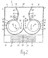
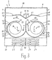
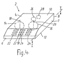
- Figures 1, 2 and 3 each schematically show a horizontal plan view Cross section through an extractor hood 2 according to the invention along the plane I-I from Fig.4.
- the extractor hood 2 has a housing 4 with a front wall 6, Side walls 7, a rear wall 8, a top wall 10 and a bottom 12.
- a left radial blower 14 and a right radial blower are located side by side 16, the vertical of which are arranged parallel and spaced apart Rotor axes of rotation 18 and 20 are shown schematically.
- the extractor hood 2 is arranged above a hotplate, not shown, in a kitchen.
- the blowers 14 and 16 suck through the air-permeable floor 12 haze or air into the Housing 4 and in the housing 4 by a grease filter, not shown, and, if desired, through an odor filter, and then drive the cleaned air depending on the setting the extractor hood 2 in recirculation mode through recirculation outlet openings 22 and 24 in the front area of the ceiling 10 back into the kitchen according to FIG. 3; or in exhaust air operation according to FIG. 1 through a ceiling exhaust air opening 26 in the ceiling 10 and an unillustrated exhaust pipe from the kitchen connected to it out into the open; or according to an exhaust air operation variant shown in FIG through a rear wall exhaust opening 28 of the rear wall 8 and an attached, Exhaust duct, not shown, from the kitchen to the outside.
- the bottom 12 is air-permeable in the suction area of the blowers 14 and 16, for example formed by expanded metal or a perforated plate or grid.
- the rotors 30 and 32 of the radial blowers 14 and 16 each convey the air tangentially through an air outlet opening 34 and 36 in parallel air flows 38 and 39 from front to back.
- the left rotor rotates counterclockwise 40 and the right rotor 32 rotates clockwise 41, as seen in plan view.
- the housing 42 and 44 of the two fans 14 and 16 are facing each other on their Sides from front to back are curved and converging then through a common partition 48 to the rear to one behind the Extended rotors 30 and 32 located area where on both sides of the partition 48 in rear blower area opening edges 50 and 52 of the housing are arranged. These opening edges 50 and 52 form together with that arranged between them Partition 48 lateral boundaries of the air outlet openings 34 and 36.
- blower duct 54 and 55 which increases in the direction of rotation of the rotor is formed.
- Flaps 60 and 62 are about pivot axes 61 and 63 between one in the figures 1 and 2 shown exhaust air operating position and one shown in Fig.3 Recirculation mode position swiveling.
- the pivot axes 61 and 63 are parallel to the rotor axes 18 and 20 arranged vertically.
- the pivot axes 61 and 63 are located far behind the opening edges 50 and 52.
- the flaps 60 and 62 have such a size that they are in position for exhaust air operation according to FIGS and 2 as far as the fan housings 42 and 44 and one between them
- Exhaust duct section 64 which extends from the air outlet openings 34 and 36 of the two fans extends to the rear.
- Each flap 60 and 62 is through an air baffle 66 and 68 to the opposite Swing axis side extended.
- Exhaust air operating position of the flaps extends that of flaps 60 and 62 exhaust air section 64 bounded on both sides to the rear up to the rear wall 8, where the rear wall exhaust air opening 28 is located between the air guiding elements 66 and 68. 1, the rear wall exhaust opening 28 is closed while it is open in the exhaust air operation shown in Fig.2.
- the air guiding elements 66 and 68 form the side walls of the one delimited by them on both sides in FIGS Abluftwegabiteses.
- the ceiling exhaust air opening 26 is located between the pivot axes 61 and 63 the flaps 60 and 64 and is open in the exhaust air operation of Fig.1, but in the Exhaust mode variant of Fig. 2 closed.
- an air guide 70 is used, which the of the flaps 60 and 62 limited exhaust air section 64 deflected upwards and extended to the ceiling exhaust opening 26.
- the air guiding elements 66 and 68 are connected with their flaps 60 and 62 in a manner fixed against movement, consist, for example, of a single one together with their flap Piece of material so that they are together with the flaps 60 and 62 respectively Pivot axes 61 and 63 are pivotable.
- the ceiling exhaust opening 26 and the rear wall exhaust opening 28 remain during the Production of the housing 4 is preferably closed and perforated marked at which the removable opening area can be separated.
- the exhaust openings 26 and 28 can already at Formed housing production and then optionally closed with a closure element become.
- flaps 60 and 62 are put together for the recirculation mode shown in FIG with their air guide elements 66 and 68 about the pivot axes 61 and 63 in the in Fig.3 position shown rotated. In this position, flaps 60 and 62 extend of their pivot axes 61 and 63 towards each other, so that they the exhaust duct section 36 close the back by placing their free flap ends 72 and 73 close together lie at a distance behind the rear end 74 of the partition 48. Die Air guiding elements 66 and 68 extend in FIG.
- the two air circulation ducts are identified by arrows 82 and 84 in FIG.
- the air circulation ducts 82 and 84 extend in a horizontal plane.
- the air of the left blower 14 flows from its air outlet opening 34 only to those located in front of the blowers on the left Forced air outlet openings 22.
- the air of the right blower 16 flows from whose air outlet opening 36 only to the circulating air outlet openings arranged on the right in front of the fans 24th
- a good degree of efficiency is achieved by the invention because the air currents two blowers 14 and 16 neither in the area of their air outlet openings 34 and 36 still at the end of the flow path at the circulating air outlet openings 22 and 24 to disturb.
- Another advantage is that through the partition 48 between the two blowers 14 and 16, the flow path within these blowers 14 and 16 extends over the full 360 degrees of the housing circumference and thus the blowers have a long flow path within their housing in which they can develop their support.
- the flow conditions of the blowers 14 and 16 remain for exhaust air operation according to FIGS. 1 and 2 and for recirculated air operation according to FIG. 3 each the same, because in both modes of operation the air outlet openings 34 and 36 between the rear end 74 of the partition 48 and the opening edges 50 and 52 remains unchanged.
Claims (9)
- Hotte d'évacuation de fumée ayant deux ventilateurs radiaux (14, 16) disposés l'un à côté de l'autre, dont les sorties d'air (34, 36) sont disposées l'une à côté de l'autre, de façon dirigée vers le même côté de la hotte d'évacuation de fumée ; avec des volets (60, 62), lesquels sont disposés de façon réglable entre une position pour le fonctionnement à circulation d'air, et une position pour le fonctionnement à évacuation d'air, autour d'axes de pivotement (61, 63) verticaux, parallèles entre eux, caractérisée en ce que les sorties d'air (34, 36) des deux ventilateurs (14, 16) sont disposées sur leur côté arrière et dans la hotte d'évacuation de fumée, de façon dirigée vers l'arrière, en ce que les axes de pivotement (61, 63) des volets (60, 62) sont disposés à une certaine distance derrière les sorties d'air (34, 36); en ce que les volets (60, 62) ont une dimension telle que, dans la position pour le fonctionnement à évacuation d'air, ils atteignent les boítiers de ventilateur (42, 44) et délimitent entre eux un tronçon de conduit d'évacuation d'air (64), lequel s'étend vers l'arrière, partant des ouvertures d'air des ventilateurs (34, 36), où par contre, les volets (60, 62) dans la position pour le fonctionnement à circulation d'air, s'étendent dans la direction transversale de la hotte d'évacuation de fumée, à une certaine distance des sorties d'air (34, 36) de ventilateur et transversalement à ces dernières, de sorte à délimiter un tronçon de départ de deux conduits à circulation d'air (82, 84), qui se prolonge entre eux et les sorties d'air (34, 36) de ventilateur ; en ce que l'un des conduits à circulation d'air (82) s'étend autour du pourtour externe de l'un des boítiers de ventilateur (42) et l'autre conduit à circulation d'air (84) s'étend autour du pourtour externe de l'autre boítier de ventilateur (46) respectivement jusqu'aux ouvertures de sortie à circulation d'air (22, 24), lesquelles sont formées dans un boítier (4) de la hotte d'évacuation de fumée, devant les ventilateurs (14, 16).
- Hotte d'évacuation de fumée selon la revendication 1, caractérisée en ce que chacun des conduits à circulation d'air (82, 84) possède ses propres ouvertures de sortie à circulation d'air (22, 24) qui sont disposées de telle sorte que leurs courants d'air ne se télescopent pas.
- Hotte d'évacuation de fumée selon l'une quelconque des revendications précédentes, caractérisée en ce que les volets (60, 62) peuvent pivoter l'un par rapport à l'autre, autour de leurs axes de pivotement (61, 63) et possèdent une longueur telle que dans une telle position de pivotement de l'un par rapport à l'autre, pour le fonctionnement à circulation d'air, ils sont adjacents l'un à l'autre et forment une paroi de séparation, laquelle empêche l'air des sorties d'air (34, 36) de s'écouler dans la partie arrière de la hotte d'évacuation de fumée.
- Hotte d'évacuation de fumée selon l'une quelconque des revendications précédentes, caractérisée en ce que, il est prévu un élément déflecteur d'air (66, 68) pour chaque volet (60, 62), qui prolonge celui-ci en direction du côté d'axe de pivotement opposé, lequel élément, lors du positionnement des volets sur le fonctionnement à évacuation d'air, prolonge le tronçon de chemin à évacuation d'air (64) délimité des deux côtés par ses volets (60, 62) dans la direction du côté arrière d'évacuation de fumée, mais qui dans la position de fonctionnement à circulation d'air des volets, délimite un tronçon des conduits à circulation d'air (82, 84), lequel s'étend entre les éléments déflecteurs d'air et les boítiers de ventilateur (42, 46).
- Hotte d'évacuation de fumée selon la revendication 4, caractérisée en ce que les éléments déflecteurs d'air (66, 68) sont liés aux volets (60, 62) de façon à être immobilisés en rotation, de sorte que, conjointement avec les volets, ils peuvent pivoter respectivement autour des axes de pivotement (61, 63).
- Hotte d'évacuation de fumée selon l'une quelconque des revendications précédentes, caractérisée par un corps déflecteur d'air (70) que l'on peut insérer éventuellement entre les axes de pivotement (61, 63), délimitant vers l'arrière un tronçon horizontal de conduit d'évacuation d'air (64), formé entre les volets (60, 62) dans leur position de fonctionnement à évacuation d'air, et à déflexion vers le haut.
- Hotte d'évacuation de fumée selon l'une quelconque des revendications précédentes, caractérisée en ce qu'elle présente dans un couvercle, une ouverture de sortie d'évacuation d'air (26) pouvant être éventuellement ouverte, laquelle se trouve dans la zone d'intervalle définie par leurs axes de pivotement (61, 63), au dessus des volets (60,62).
- Hotte d'évacuation de fumée selon l'une quelconque des revendications 3 à 8, caractérisée en ce qu'une ouverture de sortie d'évacuation d'air (28) pouvant être éventuellement ouverte, est formée dans une paroi arrière (8) de hotte d'évacuation de fumée et en ce que, dans la position de fonctionnement à évacuation d'air des volets et des éléments déflecteurs, ces éléments déflecteurs (66, 68) avec leurs extrémités libres éloignées des axes de pivotement, parviennent jusqu'à la paroi arrière de la hotte d'évacuation de fumée (8) et prolongent le tronçon de conduit d'évacuation d'air (64) délimité des deux côtés par les volets (60, 62) jusqu'à cette ouverture de sortie d'évacuation d'air (28).
- Hotte d'évacuation de fumée selon l'une quelconque des revendications précédentes, caractérisée en ce que les deux sorties d'air (34, 35) dans la direction du pourtour des ventilateurs, sont d'une part délimitées respectivement par une partie des bords des parois de ventilateurs (50, 52) et par une paroi de séparation (48) verticale disposée entre d'autres parties des bords des parois de ventilateurs, laquelle paroi sépare les courants d'air l'un de l'autre dans les deux ventilateurs radiaux (14, 16) et s'étend de l'avant vers l'arrière au moins jusqu'à un raccordement tangentiel théorique sur le côté arrière des deux rotors (30, 32) de ventilateur.
Applications Claiming Priority (2)
| Application Number | Priority Date | Filing Date | Title |
|---|---|---|---|
| DE19809559A DE19809559A1 (de) | 1998-03-05 | 1998-03-05 | Dunstabzugshaube |
| DE19809559 | 1998-03-05 |
Publications (3)
| Publication Number | Publication Date |
|---|---|
| EP0940633A2 EP0940633A2 (fr) | 1999-09-08 |
| EP0940633A3 EP0940633A3 (fr) | 2000-11-22 |
| EP0940633B1 true EP0940633B1 (fr) | 2003-07-02 |
Family
ID=7859891
Family Applications (1)
| Application Number | Title | Priority Date | Filing Date |
|---|---|---|---|
| EP99104376A Expired - Lifetime EP0940633B1 (fr) | 1998-03-05 | 1999-03-04 | Hotte d'évacuation de fumée pour cuisine |
Country Status (3)
| Country | Link |
|---|---|
| EP (1) | EP0940633B1 (fr) |
| DE (2) | DE19809559A1 (fr) |
| ES (1) | ES2201582T3 (fr) |
Families Citing this family (13)
| Publication number | Priority date | Publication date | Assignee | Title |
|---|---|---|---|---|
| JP2006010122A (ja) * | 2004-06-23 | 2006-01-12 | Matsushita Electric Ind Co Ltd | レンジフード付き高周波加熱装置 |
| DE102011051103A1 (de) * | 2011-06-16 | 2012-12-20 | Miele & Cie. Kg | Dunstabzugshaube für einen Herd oder eine Kochstelle |
| CN102261690A (zh) * | 2011-09-09 | 2011-11-30 | 宁波舜韵电子有限公司 | 一种外排和内循环式薄型抽油烟机 |
| CN102563731A (zh) * | 2011-09-09 | 2012-07-11 | 宁波舜韵电子有限公司 | 一种外排和内循环抽油烟机 |
| EP2789921B1 (fr) * | 2013-04-09 | 2017-04-05 | Silverline Küchengeräte und Handel GmbH | Hotte aspirante |
| DE102014108250A1 (de) * | 2014-06-12 | 2015-12-17 | Miele & Cie. Kg | Plattformeinrichtung |
| EP3112759B1 (fr) * | 2014-09-12 | 2019-01-30 | Wuhu Midea Kitchen Applicances Manufacturing Co., Ltd. | Hotte et volute de celle-ci |
| WO2017041415A1 (fr) | 2015-09-08 | 2017-03-16 | 广东美的厨房电器制造有限公司 | Hotte de cuisine |
| CN105673567B (zh) * | 2016-02-18 | 2018-11-13 | 广东美的厨房电器制造有限公司 | 吸油烟机及其风机组件 |
| CN105570158B (zh) * | 2016-02-18 | 2018-11-13 | 广东美的厨房电器制造有限公司 | 吸油烟机及其风机组件 |
| CN107023867A (zh) * | 2017-05-03 | 2017-08-08 | 广东美的厨房电器制造有限公司 | 应用于双风机吸油烟机的油烟引流结构和双风机吸油烟机 |
| CN109595639B (zh) * | 2017-09-30 | 2024-01-16 | 宁波方太厨具有限公司 | 一种近吸式吸油烟机 |
| CN109595645B (zh) * | 2017-09-30 | 2024-01-16 | 宁波方太厨具有限公司 | 一种近吸式吸油烟机 |
Family Cites Families (2)
| Publication number | Priority date | Publication date | Assignee | Title |
|---|---|---|---|---|
| DE7802041U1 (de) * | 1978-01-24 | 1978-05-03 | G. Bauknecht Gmbh, Elektrotechnische Fabriken, 7000 Stuttgart | Dunstabzugshaube |
| US5230327A (en) * | 1992-07-28 | 1993-07-27 | Jang Sun Sing | Kitchen smoke exhauster |
-
1998
- 1998-03-05 DE DE19809559A patent/DE19809559A1/de not_active Withdrawn
-
1999
- 1999-03-04 DE DE59906137T patent/DE59906137D1/de not_active Expired - Lifetime
- 1999-03-04 ES ES99104376T patent/ES2201582T3/es not_active Expired - Lifetime
- 1999-03-04 EP EP99104376A patent/EP0940633B1/fr not_active Expired - Lifetime
Also Published As
| Publication number | Publication date |
|---|---|
| ES2201582T3 (es) | 2004-03-16 |
| DE59906137D1 (de) | 2003-08-07 |
| DE19809559A1 (de) | 1999-09-09 |
| EP0940633A2 (fr) | 1999-09-08 |
| EP0940633A3 (fr) | 2000-11-22 |
Similar Documents
| Publication | Publication Date | Title |
|---|---|---|
| EP0940633B1 (fr) | Hotte d'évacuation de fumée pour cuisine | |
| DE60205977T2 (de) | Turbinenschaufel mit Kühlluftleiteinrichtung | |
| EP1939456A2 (fr) | Dispositif de passage d'air | |
| DE4008012C2 (de) | Lüftungsanordnung für ein einen Gefrierraum und einen Kühlraum aufweisendes Kühlgerät | |
| DE102008041739A1 (de) | Dunstabzugsvorrichtung | |
| DE1779378A1 (de) | Kombinierte Einblas- und Absaug-Belueftungsvorrichtung | |
| EP0940632B1 (fr) | Hotte d'aspiration | |
| EP3232127B1 (fr) | Hotte aspirante comprenant une grille d'évacuation | |
| DE60132218T2 (de) | Zierplatte für klimaanlage, abblaseinheit für luftauslass und klimaanlage | |
| DE2742734A1 (de) | Axialventilator | |
| DE3120569A1 (de) | "kuechendunstabzugshaube" | |
| EP2937015A1 (fr) | Table de travail | |
| EP2662636A2 (fr) | Elément intermédiaire pour hotte aspirante, notamment cheminée et hotte aspirante | |
| DE102018211809A1 (de) | Gehäuse für einen Ventilator und Ventilator | |
| DE102005013806A1 (de) | Dunstabzugshaube | |
| DE19709193B4 (de) | Radialventilator | |
| CH672543A5 (fr) | ||
| EP0667497B1 (fr) | Arrangement pour ventilation d'air | |
| DE2816669C2 (de) | Lüftungsgerät | |
| DE1946127U (de) | Entluefterhauben. | |
| DE2804027A1 (de) | Abdeckhaube fuer einen in eine wand eingebauten ventilator | |
| EP0943871B1 (fr) | Hotte d'évacuation de fumée pour cuisine | |
| EP2615383A1 (fr) | Hotte aspirante | |
| DE102007060802A1 (de) | Dunstabzugshaube, Filter für Dunstabzugshaube sowie diesbezügliches Verfahren | |
| DE3911515C2 (fr) |
Legal Events
| Date | Code | Title | Description |
|---|---|---|---|
| PUAI | Public reference made under article 153(3) epc to a published international application that has entered the european phase |
Free format text: ORIGINAL CODE: 0009012 |
|
| AK | Designated contracting states |
Kind code of ref document: A2 Designated state(s): DE ES FR GB IT SE |
|
| AX | Request for extension of the european patent |
Free format text: AL;LT;LV;MK;RO;SI |
|
| PUAL | Search report despatched |
Free format text: ORIGINAL CODE: 0009013 |
|
| AK | Designated contracting states |
Kind code of ref document: A3 Designated state(s): AT BE CH CY DE DK ES FI FR GB GR IE IT LI LU MC NL PT SE |
|
| AX | Request for extension of the european patent |
Free format text: AL;LT;LV;MK;RO;SI |
|
| 17P | Request for examination filed |
Effective date: 20001206 |
|
| AKX | Designation fees paid |
Free format text: DE ES FR GB IT SE |
|
| GRAH | Despatch of communication of intention to grant a patent |
Free format text: ORIGINAL CODE: EPIDOS IGRA |
|
| GRAH | Despatch of communication of intention to grant a patent |
Free format text: ORIGINAL CODE: EPIDOS IGRA |
|
| GRAA | (expected) grant |
Free format text: ORIGINAL CODE: 0009210 |
|
| AK | Designated contracting states |
Designated state(s): DE ES FR GB IT SE |
|
| REG | Reference to a national code |
Ref country code: GB Ref legal event code: FG4D Free format text: NOT ENGLISH |
|
| REF | Corresponds to: |
Ref document number: 59906137 Country of ref document: DE Date of ref document: 20030807 Kind code of ref document: P |
|
| REG | Reference to a national code |
Ref country code: SE Ref legal event code: TRGR |
|
| GBT | Gb: translation of ep patent filed (gb section 77(6)(a)/1977) | ||
| RAP2 | Party data changed (patent owner data changed or rights of a patent transferred) |
Owner name: BSH BOSCH UND SIEMENS HAUSGERAETE GMBH |
|
| REG | Reference to a national code |
Ref country code: ES Ref legal event code: FG2A Ref document number: 2201582 Country of ref document: ES Kind code of ref document: T3 |
|
| ET | Fr: translation filed | ||
| PLBE | No opposition filed within time limit |
Free format text: ORIGINAL CODE: 0009261 |
|
| STAA | Information on the status of an ep patent application or granted ep patent |
Free format text: STATUS: NO OPPOSITION FILED WITHIN TIME LIMIT |
|
| 26N | No opposition filed |
Effective date: 20040405 |
|
| PGFP | Annual fee paid to national office [announced via postgrant information from national office to epo] |
Ref country code: GB Payment date: 20070323 Year of fee payment: 9 Ref country code: ES Payment date: 20070323 Year of fee payment: 9 |
|
| PGFP | Annual fee paid to national office [announced via postgrant information from national office to epo] |
Ref country code: SE Payment date: 20070326 Year of fee payment: 9 |
|
| PGFP | Annual fee paid to national office [announced via postgrant information from national office to epo] |
Ref country code: FR Payment date: 20070321 Year of fee payment: 9 |
|
| EUG | Se: european patent has lapsed | ||
| GBPC | Gb: european patent ceased through non-payment of renewal fee |
Effective date: 20080304 |
|
| REG | Reference to a national code |
Ref country code: FR Ref legal event code: ST Effective date: 20081125 |
|
| PG25 | Lapsed in a contracting state [announced via postgrant information from national office to epo] |
Ref country code: SE Free format text: LAPSE BECAUSE OF NON-PAYMENT OF DUE FEES Effective date: 20080305 |
|
| PG25 | Lapsed in a contracting state [announced via postgrant information from national office to epo] |
Ref country code: FR Free format text: LAPSE BECAUSE OF NON-PAYMENT OF DUE FEES Effective date: 20080331 |
|
| REG | Reference to a national code |
Ref country code: ES Ref legal event code: FD2A Effective date: 20080305 |
|
| PG25 | Lapsed in a contracting state [announced via postgrant information from national office to epo] |
Ref country code: GB Free format text: LAPSE BECAUSE OF NON-PAYMENT OF DUE FEES Effective date: 20080304 |
|
| PG25 | Lapsed in a contracting state [announced via postgrant information from national office to epo] |
Ref country code: ES Free format text: LAPSE BECAUSE OF NON-PAYMENT OF DUE FEES Effective date: 20080305 |
|
| REG | Reference to a national code |
Ref country code: DE Ref legal event code: R081 Ref document number: 59906137 Country of ref document: DE Owner name: BSH HAUSGERAETE GMBH, DE Free format text: FORMER OWNER: BSH BOSCH UND SIEMENS HAUSGERAETE GMBH, 81739 MUENCHEN, DE Effective date: 20150402 |
|
| PGFP | Annual fee paid to national office [announced via postgrant information from national office to epo] |
Ref country code: DE Payment date: 20150331 Year of fee payment: 17 |
|
| PGFP | Annual fee paid to national office [announced via postgrant information from national office to epo] |
Ref country code: IT Payment date: 20150330 Year of fee payment: 17 |
|
| REG | Reference to a national code |
Ref country code: DE Ref legal event code: R119 Ref document number: 59906137 Country of ref document: DE |
|
| PG25 | Lapsed in a contracting state [announced via postgrant information from national office to epo] |
Ref country code: DE Free format text: LAPSE BECAUSE OF NON-PAYMENT OF DUE FEES Effective date: 20161001 |
|
| PG25 | Lapsed in a contracting state [announced via postgrant information from national office to epo] |
Ref country code: IT Free format text: LAPSE BECAUSE OF NON-PAYMENT OF DUE FEES Effective date: 20160304 |