EP2937015A1 - Table de travail - Google Patents
Table de travail Download PDFInfo
- Publication number
- EP2937015A1 EP2937015A1 EP15164529.8A EP15164529A EP2937015A1 EP 2937015 A1 EP2937015 A1 EP 2937015A1 EP 15164529 A EP15164529 A EP 15164529A EP 2937015 A1 EP2937015 A1 EP 2937015A1
- Authority
- EP
- European Patent Office
- Prior art keywords
- suction
- housing
- filter
- calming
- filter unit
- Prior art date
- Legal status (The legal status is an assumption and is not a legal conclusion. Google has not performed a legal analysis and makes no representation as to the accuracy of the status listed.)
- Granted
Links
- 230000001914 calming effect Effects 0.000 claims abstract description 33
- 230000030279 gene silencing Effects 0.000 claims abstract description 14
- 238000011282 treatment Methods 0.000 claims abstract description 6
- 239000002537 cosmetic Substances 0.000 claims abstract description 3
- 239000000428 dust Substances 0.000 claims description 36
- 238000013016 damping Methods 0.000 claims description 14
- 238000011144 upstream manufacturing Methods 0.000 claims description 2
- 238000011045 prefiltration Methods 0.000 description 12
- OKTJSMMVPCPJKN-UHFFFAOYSA-N Carbon Chemical compound [C] OKTJSMMVPCPJKN-UHFFFAOYSA-N 0.000 description 10
- 239000002245 particle Substances 0.000 description 9
- 239000012530 fluid Substances 0.000 description 8
- 238000009413 insulation Methods 0.000 description 8
- 238000000605 extraction Methods 0.000 description 3
- 238000007789 sealing Methods 0.000 description 3
- 238000010276 construction Methods 0.000 description 2
- 238000001556 precipitation Methods 0.000 description 2
- 238000009423 ventilation Methods 0.000 description 2
- 238000004140 cleaning Methods 0.000 description 1
- 238000011109 contamination Methods 0.000 description 1
- 230000007423 decrease Effects 0.000 description 1
- 230000001419 dependent effect Effects 0.000 description 1
- 230000005484 gravity Effects 0.000 description 1
- 238000004519 manufacturing process Methods 0.000 description 1
- 230000002093 peripheral effect Effects 0.000 description 1
- 239000002244 precipitate Substances 0.000 description 1
- 230000000717 retained effect Effects 0.000 description 1
- 230000003068 static effect Effects 0.000 description 1
- 230000007704 transition Effects 0.000 description 1
Images


Classifications
-
- A—HUMAN NECESSITIES
- A45—HAND OR TRAVELLING ARTICLES
- A45D—HAIRDRESSING OR SHAVING EQUIPMENT; EQUIPMENT FOR COSMETICS OR COSMETIC TREATMENTS, e.g. FOR MANICURING OR PEDICURING
- A45D44/00—Other cosmetic or toiletry articles, e.g. for hairdressers' rooms
- A45D44/02—Furniture or other equipment specially adapted for hairdressers' rooms and not covered elsewhere
-
- A—HUMAN NECESSITIES
- A45—HAND OR TRAVELLING ARTICLES
- A45D—HAIRDRESSING OR SHAVING EQUIPMENT; EQUIPMENT FOR COSMETICS OR COSMETIC TREATMENTS, e.g. FOR MANICURING OR PEDICURING
- A45D29/00—Manicuring or pedicuring implements
-
- B—PERFORMING OPERATIONS; TRANSPORTING
- B08—CLEANING
- B08B—CLEANING IN GENERAL; PREVENTION OF FOULING IN GENERAL
- B08B15/00—Preventing escape of dirt or fumes from the area where they are produced; Collecting or removing dirt or fumes from that area
-
- B—PERFORMING OPERATIONS; TRANSPORTING
- B25—HAND TOOLS; PORTABLE POWER-DRIVEN TOOLS; MANIPULATORS
- B25H—WORKSHOP EQUIPMENT, e.g. FOR MARKING-OUT WORK; STORAGE MEANS FOR WORKSHOPS
- B25H1/00—Work benches; Portable stands or supports for positioning portable tools or work to be operated on thereby
- B25H1/20—Work benches; Portable stands or supports for positioning portable tools or work to be operated on thereby with provision for shielding the work area
-
- F—MECHANICAL ENGINEERING; LIGHTING; HEATING; WEAPONS; BLASTING
- F24—HEATING; RANGES; VENTILATING
- F24F—AIR-CONDITIONING; AIR-HUMIDIFICATION; VENTILATION; USE OF AIR CURRENTS FOR SCREENING
- F24F3/00—Air-conditioning systems in which conditioned primary air is supplied from one or more central stations to distributing units in the rooms or spaces where it may receive secondary treatment; Apparatus specially designed for such systems
- F24F3/12—Air-conditioning systems in which conditioned primary air is supplied from one or more central stations to distributing units in the rooms or spaces where it may receive secondary treatment; Apparatus specially designed for such systems characterised by the treatment of the air otherwise than by heating and cooling
- F24F3/16—Air-conditioning systems in which conditioned primary air is supplied from one or more central stations to distributing units in the rooms or spaces where it may receive secondary treatment; Apparatus specially designed for such systems characterised by the treatment of the air otherwise than by heating and cooling by purification, e.g. by filtering; by sterilisation; by ozonisation
- F24F3/163—Clean air work stations, i.e. selected areas within a space which filtered air is passed
Definitions
- the present invention relates to a work table with an integrated suction, in particular for cosmetic nail treatments.
- Such work tables in particular nail care tables, have one or more treatment stations and an integrated with the table suction with filter.
- the DE 20 2013 100 737 shows a nail care table with multiple treatment stations, each with a suction, wherein the respective suction openings are connected to each other and with a single suction device.
- a substantially closed housing which is closed on its upper side by a table top.
- the table top extends in the lateral extent over the entire housing and has a first suction opening in a region.
- the housing has an outlet opening in another area, wherein the first suction opening is connected to the outlet opening by means of a suction channel.
- a constriction, a filter unit and a fan are arranged one after the other in the suction direction.
- the fan is arranged downstream of a first calming and sound damping zone in the suction direction.
- a multiple deflection of the sound waves is prevented that they pass directly from the housing to the outside.
- the noise emissions are reduced. The greater the number of deflections and the better the sound insulation, the lower are the disturbing noise emissions.
- the remaining areas of the suction channel may also be lined with a sound insulation.
- baffles are arranged in the corner regions of the suction channel of the calming and sound damping zone to round off these corner regions. The reduction of the flow resistance through these rounded baffles leads at the same time to a reduction of the pressure loss over the calming and sound damping zone.
- the filter unit is arranged laterally of the constriction.
- the height can be reduced because of the effectiveness of the filter a certain thickness is needed.
- only space for the deflection of the extracted air is required below the constriction, which in turn is arranged below the suction opening. Since this space requirement is very low, a low overall height can be realized.
- the filter unit has filters whose filter surfaces are arranged substantially vertically and which can be flowed through substantially horizontally. This arrangement of the filter ensures that only the entrained particles or fluids in the air flow hit the filter and get caught on or in this. Particles or fluids that precipitate from the airflow due to gravity or centrifugal forces will remain in front of the filters and thus will not cause unnecessary clogging of the filters. The filters must therefore be cleaned less often.
- At least one pre-filter for example of classes M5 and / or F8, is arranged, which is followed by an activated carbon filter, which is preferably pleated and which is followed by a fine filter, for example class H13.
- an activated carbon filter which is preferably pleated and which is followed by a fine filter, for example class H13.
- the arrangement of several different filters allows to achieve optimum filter performance with the lowest possible pressure loss.
- a plurality of prefilters are arranged one after another, for example, a first prefilter of class M5 is followed by a second prefilter of class F8.
- a connection unit of the filter unit is arranged upstream in the housing in the suction direction, wherein the connection unit has a second suction opening, through which alternatively or additionally air can be sucked.
- the connection unit By arranging the connection unit in front of the filter unit, the same filter unit can be used for cleaning the air, regardless of whether it is sucked through the first suction opening or through the connection unit.
- a Filter bag (similar to a vacuum cleaner bag), for example, the class F7, be arranged at the second suction opening, whereby the air flowing through the second suction opening air is filtered. With this arrangement, the same filter unit can be used to clean the air up to at least filter stage H13.
- a closure of the second suction opening can be removed and the first suction opening can be closed, for example by a tightly closing mat.
- a coarse dust drawer is arranged in the suction direction after the constriction.
- the arrangement of the coarse dust drawer shortly after the constriction causes on the one hand, that all sucked through the first suction air strikes the coarse dust drawer.
- the coarse dust drawer causes a deflection of the air flow, which favors precipitation of the particles and / or fluids from the air flow.
- the flow velocity in this area decreases sharply, which additionally favors the precipitation of particles and / or fluids.
- a second coarse dust drawer in the suction direction after the constriction and in front of the filter unit, adjacent to the filter unit.
- particles and / or fluids that are not left in the first coarse dust drawer can be collected.
- particles falling from the filter unit can be collected with the second coarse dust drawer.
- connection unit is preferably arranged above the second coarse dust drawer. This allows, in the case of extraction via the connection unit and not via the first suction opening, the collection of the particles and / or fluids by means of the second coarse dust drawer. In the case of using a filter bag at the second suction, can be dispensed with the second coarse dust drawer, since the coarser particles contained in the air flow and / or fluids that would be collected without the filter bag in the second Grobsaugschublade retained in the filter bag become.
- a second calming and silencing zone is arranged downstream of the first calming and silencing zone in the suctioning direction. This increases the sound insulation and the suction noises are even less perceptible.
- the constriction, the filter unit, the fan and the calming and sound damping zone are arranged side by side, substantially in a horizontal plane, and immediately below the table top.
- This allows a compact construction, i. a construction with the lowest possible height.
- this arrangement allows a generous and uniform configuration of the cross section of the suction channel, which means lower flow losses.
- Lower flow losses allow the use of fans with comparatively smaller suction capacities.
- lower power fans mean less noise.
- constriction and the filter unit are arranged side by side, substantially in a horizontal plane, and immediately below the table top, and the fan and the calming and silencing zone are superimposed, substantially in a vertical plane.
- This design allows a very lightweight design on one side of the work table, while all elements of the suction device can be arranged on the other side.
- the height of the table is thus influenced only in one edge region on one side, while the other, opposite side can be formed with very low height.
- the closed housing is arranged on table legs and / or drawer blocks such that the table top is at an advantageous working height.
- Tables with adjustable height are also conceivable, the adjustability with table legs and / or drawer blocks can be realized.
- work tables are stationary, but they can also be provided with rollers so that they are rollable.
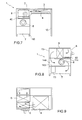
- FIG. 1 shows a perspective view of a first embodiment of an inventive work table, which has a substantially closed housing 1, which is closed on its upper side by a table top 2.
- the illustrated table has a substantially rectangular floor plan.
- the table may also have other shapes, wherein the housing 1 itself may have a different shape or only the table top 2.
- the table may, for example, have rounded transitions between two adjacent sides or may be oval, elliptical, circular or kidney-shaped.
- the design of the table top 2 is less limited by the feasibility of manufacturing than the design of the housing. 1
- the housing 1 is arranged on table legs 10 such that the top of the table top is at a comfortable working height. At the same time created by the presence of the table legs a space under the housing 1, which allows a comfortable sitting at the table. Viewed from the front, the table is made less thick in the central area, which increases the legroom, i. the available space under the table, additionally enlarged. Subsequent to the central area, on both sides of the central area, the housing has a greater thickness, which leads to the reduction of the free space to the floor below this area.
- the table top 2 here has a plurality of suction openings 23 in a central area.
- suction openings may be present in several areas and represent different workstations.
- the nails of a first hand may be handled by one person at a first workstation and the nails of a second hand at a second workstation.
- the area of the suction openings corresponds approximately to the dimensions of a palm. However, it can also be larger and, for example, have the size of two, three or more palms.
- the table top 2 is detachably fastened to the housing 1, for example with quick-release fasteners.
- a seal is provided which prevents the inadvertent entry of air.
- a magnetic fixing can be used instead of the quick-release fasteners.
- the table top 2 extends laterally to the outer boundary of the housing 1.
- the table top 2 can protrude laterally over the housing 1.
- the design of the suction openings 23 is versatile, for example, the table top 2, a table leaf 21 and arranged thereon or recessed cover 22, wherein in the presence of a cover 22, the suction openings 23 are formed in this.
- the cover 22 may extend over part or all of the table top 21.
- the illustrated suction openings 23 are regularly arranged circular holes. However, other embodiments, such as oval, slot, lamellar openings are also conceivable.
- the cover 22 may also be formed in a sieve-shaped.
- the suction opening 23 may also be a pattern of suction openings, for example holes with a diameter of 1 to 3 centimeters, which are distributed uniformly, for example at intervals of 15 to 55 millimeters, in a region of the table top 2.
- the front side i. arranged in the front a first coarse dust drawer 4, which can be pulled out to the front.
- the coarse dust drawer 4 is substantially cup-shaped, i. it has a closed bottom surface and a closed border.
- the first coarse dust drawer 4 has a circumferential sealing lip which, in the inserted state of the first coarse dust drawer 4, preferably completely seals it against the housing 1.
- the first coarse dust drawer 4 has quick-release fasteners 41, with which the first coarse dust drawer 4 quickly secure us is detachably fastened to the housing.
- a magnetic fixing can be used instead of the quick-release fasteners.
- a handle 42 is arranged on the front side of the first coarse dust drawer 4 in order to be able to take it out better.
- connection unit 8 is arranged frontally, frontally, which allows the connection of, for example, a hose.
- a connected hose can for example be connected to a suction head or to another unit which has suction openings.
- a treatment station for a pedicure can be connected.
- the connection unit 8 can alternatively also be arranged laterally on the housing 1.
- a circumferential sealing lip seals the connection unit 8 against the housing 1, wherein the connection unit 8 by means of quick fasteners 84 on the housing 1 is releasably fastened.
- a magnetic fixing can be used instead of the quick-release fasteners.
- a second coarse dust drawer 40 is arranged frontally, which can be pulled out to the front.
- a lateral arrangement in the housing 1 and a corresponding lateral extraction of the second coarse dust drawer 40 is an alternative.
- the second coarse dust drawer 40 has a peripheral seal and can be detachably fastened to the housing by means of quick fasteners 401.
- the second coarse dust drawer 40 end face with a handle 402 equipped to facilitate the extraction.
- an operating unit 9 is arranged frontally on the housing 1.
- the suction can be switched on or off or the suction power can be adjusted.
- Further operating elements for further devices or connections for further devices or lamps can be integrated in the control unit.
- the other controls or connections can be arranged at a different location of the table on the housing.
- Other devices include lamps, radiant heaters or UV lamps or laser beam devices.
- An outlet opening 73 is arranged on the right side in the housing 1, wherein the first suction opening 23 forms the beginning of a suction channel arranged in the housing 1 and the outlet opening 73 represents the end of the same suction channel.
- the illustrated outlet opening 73 is a lamellar insert. However, it can also be configured in the form of a lattice or realized by conventional ventilation covers in the ventilation sector.
- the FIG. 2 shows a frontal sectional view of a work table according to the FIG. 1 with an enlarged table top 2, which projects laterally beyond the housing 1. However, the table top 2 can survive on all sides of the housing 1.
- the table top 2 has a table top 21 and a cover 22, wherein the cover 22 is arranged above a recess 211 arranged in the table top 21. Below the recess 211 and laterally sealingly adjacent thereto, a constriction 3 is arranged. The constriction 3 adjoins the recess 211 on the underside of the tabletop 21 and tapers in the suction direction, ie downwards at this point.
- the lowermost part of the constriction 3 is arranged at a distance from the first coarse dust drawer 4, which is located below an outlet of the constriction 3.
- the outlet of the constriction is arranged substantially centrally with respect to the lateral dimensions of the first coarse dust drawer 4.
- the flow of sucked air is indicated by arrows in the FIGS. 2, 3 and 5 to 9 illustrated.
- the extracted air flows into a first space 11 of the suction duct, the first space 11 being in the front central area of the housing 11 and upwardly through the inside of the table 21 and down through the first coarse dust drawer 4 is limited.
- the first space 11 is bounded laterally, in this view to the right by a first side wall 111, to the rear by a second side wall 112 and to the left by a third side wall 113.
- the first and second side walls 111, 112 close the first space 11 sealingly from the environment.
- the third side wall 113 is sealing only in its rear area. In its front area, it has a passage which forms the connection to a second space 12. Alternatively, the third side wall 113 is formed only in the rear area.
- the extracted air is diverted in a substantially horizontal direction, the main flow being directed towards the second space 112.
- the second space 112 is left of the first room 111 then and passing into this.
- the second space 112 is bounded above by the table top 21 and below by the second coarse dust drawer 40.
- the second space 112 is limited by a tightly sealed housing outer wall.
- connection unit 8 has a plate 80 detachably connected to the housing 1, with a second suction opening 81 arranged therein.
- the second suction opening 81 is formed as a nozzle 82 with a releasable closure 83.
- the nozzle 82 may be formed on the inner side of the plate 80 flush with this. Preferably, however, the nozzle 82 protrudes into the inner side of the plate 80 so that a filter bag 54 can be slipped over the nozzle 82.
- the filter bag 54 has the function of a pre-filter, for example of class F7.
- the second coarse dust drawer 40 is disposed below the inlet portion of the nozzle 82.
- the filter unit 5 connects to the rear of the second space 112 to this. By removing the connection unit 8, the filter unit 5 is accessible from the outside. Alternatively, the filter unit can be configured laterally accessible. For this purpose, a second, lateral, tightly closed access would be necessary.
- the filter unit 5 has a first pre-filter 50, a second pre-filter 51, an activated carbon filter 52 and a fine filter 53, which are arranged one behind the other in the suction direction in the above-mentioned order.
- the filters 50, 51, 52, 53 can be replaced individually or as a package, for example a cassette, by removing the table top 2.
- the filters 50, 51, 52, 53 may be arranged in a common cassette be, which is laterally pulled out of the housing and which is sealed in the inserted state and is fastened with quick fasteners on the housing.
- the pre-filter or filters 50, 51 may be separately arranged and the activated carbon filter 52 may be arranged together with the fine filter 53 in a common cassette.
- the filters 50, 51, 52, 53 are designed as mats, wherein the thickness of the filter parallel to the flow direction is smaller than the filter dimensions transversely to the flow direction.
- the thickness is 1 to 10 centimeters and the transverse dimensions 15 to 40 centimeters.
- the filters are arranged in the housing 1 such that the suction direction is substantially horizontal and thus perpendicular to the transverse dimensions of the filters.
- the rear boundary of the filter unit 5, i. the rearwardly facing surface of the fine filter 53 is formed substantially flush with the rearward second side wall 112 of the first space 11.
- the first pre-filter 50 which must be cleaned or changed more frequently than the second pre-filter 51 and the two other filters 52, 53, can be removed through the opening in the housing 1 exposed by the removal of the terminal unit 8.
- the second pre-filter 51, the activated carbon filter 52 and the fine filter 53 can be replaced by removing the table top 2.
- an insert shell could be used, which can be removed by the opening exposed by the removal of the connection unit 8.
- a further alternative forms a filter bag 54, which is on the inside of the housing 1, over the inner end of the nozzle 82 can be folded.
- a third space 113 is arranged, in which the air emerging from the filter unit 5 flows.
- the third space 113 is directed upward through the table top 2, below through the bottom of the housing 1 and laterally outwards, and bounded at the rear by a side wall of the housing 1. Laterally towards the center of the table, the third space 113 merges into a fourth space 114, which is located behind the second side wall 112 of the first space 11.
- the fourth space 114 together with the third space 113, interposes a connection channel the filter unit 5 and the fan 6, which is then arranged on the fourth space.
- the fan 6 is arranged on the opposite side of the filter unit 5 with respect to the middle part of the table.
- the fan is arranged in the rear area of the table, so that it is arranged substantially in line with the third and fourth spaces 113, 114.
- the fan 6 is a high-pressure centrifugal fan, which has a volume flow of 100 to 400 cubic meters per hour at a static pressure of up to 500 to 650 Pascal and has an electric motor, which with a voltage of 220 volts is operated.
- the fan has a volume flow control, which ensures that the set flow rate remains constant even with increasing contamination of the filter.
- a first calming and sound damping zone 7 is arranged on its discharge side, which connects the fan 6 with the environment through an outlet opening 73 in the housing 1.
- the first calming and sound-damping zone 7 has a laterally closed channel with at least one deflection 71, wherein the inside of the channel walls in this zone are provided with a sound insulation 72.
- the first calming and silencing zone 7 may have two, three or more baffles 71.
- the air is deflected by 90 degrees and then deflected 180 degrees before the air reaches the suction channel, i. In this area, the first calming and silencing zone 7 leaves through the outlet opening 73 on the side of the housing 1.
- the deflections 71 take place by means arranged in the corner regions of the first calming and silencing zone 7 baffles 74 which are rounded in a circle and extend over the entire height of the housing 1.
- baffles 74 which are rounded in a circle and extend over the entire height of the housing 1.
- a tubular structure for example a bellows, can be used in order to redirect the air flow as loss-free as possible.
- baffles 15 such as those of the calming and sound absorbing zone 7 can be arranged in those corner regions of the suction channel, in which the sucked air is deflected in order to reduce the flow resistance. Like in the FIG. 3 illustrated, such baffles 15 are arranged in a corner region of the second space 12 and in a corner region of the third space 13. Such baffles may also be present in the other embodiments, even if this is not shown in the figures.
- baffles for continuous flow deflection, as well as the lining of the suction channel with a sound insulation can also be realized in the second calming and soundproofing zone.
- the operating unit 9 is arranged.
- FIG. 4 shows a perspective view of a second embodiment of a work table according to the invention, wherein, in contrast to the first embodiment, the housing 1 of the table is not arranged on table legs 10 but on drawer blocks 100.
- the table legs 10 and the drawer blocks can be formed with rollers, with lockable rollers or support elements.
- FIG. 5 shows a frontal sectional view of a work table of a third embodiment of an inventive work table and the FIG. 6 shows a sectional view from above of this table.
- a second calming and Noise reduction zone 70 is connected to the first calming and sound damping zone 7, wherein in this embodiment the second calming and sound damping zone 70 has two 180 degree deflections 701.
- the inner wall of the suction channel is provided with a sound insulation 702 and the suction channel is connected through a laterally arranged outlet opening 703 with the environment.
- the table legs and the drawer blocks can be formed with rollers, with lockable rollers or support elements.
- the second calming and silencing zone 70 is an element which is arrangeable to the housing 1 of the first embodiment.
- the second calming and silencing zone 70 may also be an element which forms part of the housing 1 and is integrated therein.
- FIGS. 7, 8 and 9 show a front view, a side view and a plan view of a fourth embodiment of an inventive work table.
- the fan 6 and the first calming and sound-damping zone 7 are not arranged on the opposite side of the filter unit 5 with respect to the center of the table, but are arranged on the same side, below the filter unit 5.
- the second coarse dust drawer 40 and the filter unit 5 arranged downstream in the flow direction are arranged on a first floor 114 of the housing 1.
- the first floor 114 has an opening following the filter unit 5, ie in the region of the third room 13 or the first floor 114 is not continued after the filter unit 5, so that a downwardly directed opening in the region of the third space 13 is formed.
- the air leaving the filter unit 5 is guided downwards through this opening into an alternative fourth space 14a, which in this embodiment is located below the third space 13.
- a second floor 115 is formed, which causes the space in the fourth alternative incoming air into the horizontal, is deflected in the direction of the fan 6.
- the fan 6 is arranged substantially centrally below the filter unit 5 on the second floor 115.
- the second floor 115 has, after the fan 6, a downwardly directed opening or only extends to the outlet end of the fan 6, so that a downwardly directed opening is subsequently formed on the fan 6.
- the air exiting the fan 6 is deflected downwards and flows into the calming and silencing zone 7 arranged below the fan 6 and the alternative fourth room 14a, before it exits the housing 1 laterally through the outlet opening 73.
- the housing 1 is supported on the side with the filter unit 5, the fan 6 and the first calming and silencing zone 7 on short legs 10 and on the side opposite this side by long legs table 10.
- a drawer block can be used instead of the long table legs 10.
- LIST OF REFERENCE NUMBERS 1 casing 52 Activated carbon filter 11 First room 53 fine filter 111 First sidewall 54 filter bag 112 Second side wall 6 fan 113 Third sidewall 7 First calming and 114 First floor Sound attenuation zone 115 Second floor 71 redirection 12 Second room 72 soundproofing 13 Third room 73 outlet 14 Fourth room 74 baffle 14a Alternative fourth room 70 Second reassurance and 15 baffle Sound attenuation zone 2 tabletop 701 redirection 21 tabletop 702 soundproofing 211 recess 703 outlet 22 edition 8th connection unit 23 First suction opening 80 plate 3 narrowing 81 Second suction opening 4 First coarse dust drawer 82 Support 41 quick release 83 shutter 42 Handle 84 quick release 40 Second coarse dust drawer 9 operating unit 401 quick release 91 fastener 40
Applications Claiming Priority (1)
| Application Number | Priority Date | Filing Date | Title |
|---|---|---|---|
| CH00624/14A CH709559A2 (de) | 2014-04-24 | 2014-04-24 | Arbeitstisch |
Publications (2)
| Publication Number | Publication Date |
|---|---|
| EP2937015A1 true EP2937015A1 (fr) | 2015-10-28 |
| EP2937015B1 EP2937015B1 (fr) | 2016-04-20 |
Family
ID=52997920
Family Applications (1)
| Application Number | Title | Priority Date | Filing Date |
|---|---|---|---|
| EP15164529.8A Not-in-force EP2937015B1 (fr) | 2014-04-24 | 2015-04-21 | Table de travail |
Country Status (2)
| Country | Link |
|---|---|
| EP (1) | EP2937015B1 (fr) |
| CH (1) | CH709559A2 (fr) |
Cited By (4)
| Publication number | Priority date | Publication date | Assignee | Title |
|---|---|---|---|---|
| CN107095436A (zh) * | 2017-06-29 | 2017-08-29 | 林仁昌 | 集成式理发专用柜 |
| CN108647120A (zh) * | 2018-05-07 | 2018-10-12 | 南京璀错网络科技有限公司 | 一种计算机硬件故障检测装置 |
| EP4112195A1 (fr) * | 2021-06-29 | 2023-01-04 | Sy Huy Ha | Table de traitement |
| CN117138501A (zh) * | 2023-11-01 | 2023-12-01 | 昊朗科技(佛山)有限公司 | 一种固废分离与收集装置 |
Families Citing this family (1)
| Publication number | Priority date | Publication date | Assignee | Title |
|---|---|---|---|---|
| KR102439965B1 (ko) * | 2020-12-09 | 2022-09-02 | 강경일 | 네일아트용 테이블 |
Citations (7)
| Publication number | Priority date | Publication date | Assignee | Title |
|---|---|---|---|---|
| US4248162A (en) * | 1979-07-26 | 1981-02-03 | Spellman High Voltage Electronics Corporation | Table with electrostatic air purifier/cleaner |
| US4647295A (en) * | 1986-04-28 | 1987-03-03 | Christ Clifford W | Worktop air cleaner |
| US5787903A (en) * | 1997-03-25 | 1998-08-04 | Blackshear; Mary Jane | Manicurist workstation |
| US20030024442A1 (en) * | 2001-08-03 | 2003-02-06 | Beaunix Co., Ltd. | Nail caring table having vacuum purifier |
| DE202013100737U1 (de) | 2013-02-19 | 2013-03-26 | Chi-Man Tran | Behandlungstisch mit integrierter Mehrpositionen-Absaugung |
| CN202959404U (zh) * | 2012-12-06 | 2013-06-05 | 李润初 | 一种环保的美甲台 |
| DE202013105293U1 (de) * | 2013-11-21 | 2013-12-02 | Ali Aklikli | Arbeitstisch zur Maniküre |
-
2014
- 2014-04-24 CH CH00624/14A patent/CH709559A2/de not_active Application Discontinuation
-
2015
- 2015-04-21 EP EP15164529.8A patent/EP2937015B1/fr not_active Not-in-force
Patent Citations (7)
| Publication number | Priority date | Publication date | Assignee | Title |
|---|---|---|---|---|
| US4248162A (en) * | 1979-07-26 | 1981-02-03 | Spellman High Voltage Electronics Corporation | Table with electrostatic air purifier/cleaner |
| US4647295A (en) * | 1986-04-28 | 1987-03-03 | Christ Clifford W | Worktop air cleaner |
| US5787903A (en) * | 1997-03-25 | 1998-08-04 | Blackshear; Mary Jane | Manicurist workstation |
| US20030024442A1 (en) * | 2001-08-03 | 2003-02-06 | Beaunix Co., Ltd. | Nail caring table having vacuum purifier |
| CN202959404U (zh) * | 2012-12-06 | 2013-06-05 | 李润初 | 一种环保的美甲台 |
| DE202013100737U1 (de) | 2013-02-19 | 2013-03-26 | Chi-Man Tran | Behandlungstisch mit integrierter Mehrpositionen-Absaugung |
| DE202013105293U1 (de) * | 2013-11-21 | 2013-12-02 | Ali Aklikli | Arbeitstisch zur Maniküre |
Cited By (5)
| Publication number | Priority date | Publication date | Assignee | Title |
|---|---|---|---|---|
| CN107095436A (zh) * | 2017-06-29 | 2017-08-29 | 林仁昌 | 集成式理发专用柜 |
| CN108647120A (zh) * | 2018-05-07 | 2018-10-12 | 南京璀错网络科技有限公司 | 一种计算机硬件故障检测装置 |
| EP4112195A1 (fr) * | 2021-06-29 | 2023-01-04 | Sy Huy Ha | Table de traitement |
| CN117138501A (zh) * | 2023-11-01 | 2023-12-01 | 昊朗科技(佛山)有限公司 | 一种固废分离与收集装置 |
| CN117138501B (zh) * | 2023-11-01 | 2024-02-20 | 昊朗科技(佛山)有限公司 | 一种固废分离与收集装置 |
Also Published As
| Publication number | Publication date |
|---|---|
| CH709559A2 (de) | 2015-10-30 |
| EP2937015B1 (fr) | 2016-04-20 |
Similar Documents
| Publication | Publication Date | Title |
|---|---|---|
| EP2937015B1 (fr) | Table de travail | |
| EP2095025B1 (fr) | Dispositif d'aspiration de fumées | |
| DE3513902C2 (fr) | ||
| DE202012013527U1 (de) | Montageeinheit mit Kochfeld und Dunstabzugsvorrichtung | |
| EP3000158A1 (fr) | Support de ventilateur, en particulier d'une armoire électrique | |
| DE10325007A1 (de) | Abzugshaube für einen Küchenherd | |
| DE202018006721U1 (de) | Dunstabzug zum Abzug von auf einem Kochfeld erzeugter Abluft in vertikal unterhalb einer Kochfeldebene weisender Richtung | |
| WO1982003114A1 (fr) | Local a air conditionne et procede pour son utilisation | |
| EP0940633B1 (fr) | Hotte d'évacuation de fumée pour cuisine | |
| DE102020114719B4 (de) | Kochwrasenabzug | |
| WO2009062809A2 (fr) | Dispositif d'aspiration de vapeurs | |
| DE2836708A1 (de) | Mobiles reinluftgeraet | |
| EP2613096B1 (fr) | Cheminée de ventilation domestique avec quatre plaques de filtre parallèles | |
| DE3235927C1 (de) | Reinraumkammer | |
| EP2615383B1 (fr) | Hotte aspirante | |
| EP2829808B1 (fr) | Hotte aspirante | |
| EP3869106A1 (fr) | Plaque de cuisson pourvu de point de cuisson et dispositif d'aspiration pour vapeurs de cuisson | |
| EP3354178B1 (fr) | Aspirateur | |
| WO2000016017A1 (fr) | Procede et dispositif permettant de proteger les personnes et/ou produits de particules en suspension dans l'air | |
| WO2006081884A1 (fr) | Dispositif d'evacuation de fumees pour la cuisine | |
| EP3653940A1 (fr) | Hotte aspirante | |
| DE2913871A1 (de) | Staubabsaugvorrichtung in einem arbeitstisch der feinwerktechnik fuer sitzende taetigkeit | |
| DE202017101095U1 (de) | Staubabsauggerät | |
| DE102022119859A1 (de) | Dunstabzugseinrichtung und Verfahren zum Betreiben | |
| DE3042457C2 (fr) |
Legal Events
| Date | Code | Title | Description |
|---|---|---|---|
| PUAI | Public reference made under article 153(3) epc to a published international application that has entered the european phase |
Free format text: ORIGINAL CODE: 0009012 |
|
| AK | Designated contracting states |
Kind code of ref document: A1 Designated state(s): AL AT BE BG CH CY CZ DE DK EE ES FI FR GB GR HR HU IE IS IT LI LT LU LV MC MK MT NL NO PL PT RO RS SE SI SK SM TR |
|
| AX | Request for extension of the european patent |
Extension state: BA ME |
|
| 17P | Request for examination filed |
Effective date: 20151112 |
|
| RBV | Designated contracting states (corrected) |
Designated state(s): AL AT BE BG CH CY CZ DE DK EE ES FI FR GB GR HR HU IE IS IT LI LT LU LV MC MK MT NL NO PL PT RO RS SE SI SK SM TR |
|
| GRAP | Despatch of communication of intention to grant a patent |
Free format text: ORIGINAL CODE: EPIDOSNIGR1 |
|
| RIC1 | Information provided on ipc code assigned before grant |
Ipc: A47B 37/00 20060101AFI20160105BHEP Ipc: A45D 29/00 20060101ALI20160105BHEP Ipc: B60R 13/08 20060101ALI20160105BHEP Ipc: B08B 15/00 20060101ALI20160105BHEP Ipc: A45D 44/02 20060101ALI20160105BHEP |
|
| GRAS | Grant fee paid |
Free format text: ORIGINAL CODE: EPIDOSNIGR3 |
|
| INTG | Intention to grant announced |
Effective date: 20160121 |
|
| GRAA | (expected) grant |
Free format text: ORIGINAL CODE: 0009210 |
|
| AK | Designated contracting states |
Kind code of ref document: B1 Designated state(s): AL AT BE BG CH CY CZ DE DK EE ES FI FR GB GR HR HU IE IS IT LI LT LU LV MC MK MT NL NO PL PT RO RS SE SI SK SM TR |
|
| REG | Reference to a national code |
Ref country code: GB Ref legal event code: FG4D Free format text: NOT ENGLISH |
|
| REG | Reference to a national code |
Ref country code: CH Ref legal event code: EP |
|
| REG | Reference to a national code |
Ref country code: AT Ref legal event code: REF Ref document number: 791379 Country of ref document: AT Kind code of ref document: T Effective date: 20160515 |
|
| REG | Reference to a national code |
Ref country code: IE Ref legal event code: FG4D Free format text: LANGUAGE OF EP DOCUMENT: GERMAN |
|
| REG | Reference to a national code |
Ref country code: CH Ref legal event code: NV Representative=s name: ISLER AND PEDRAZZINI AG, CH |
|
| REG | Reference to a national code |
Ref country code: DE Ref legal event code: R096 Ref document number: 502015000020 Country of ref document: DE |
|
| REG | Reference to a national code |
Ref country code: SE Ref legal event code: TRGR |
|
| REG | Reference to a national code |
Ref country code: LT Ref legal event code: MG4D |
|
| REG | Reference to a national code |
Ref country code: FR Ref legal event code: PLFP Year of fee payment: 2 |
|
| REG | Reference to a national code |
Ref country code: NL Ref legal event code: MP Effective date: 20160420 |
|
| PG25 | Lapsed in a contracting state [announced via postgrant information from national office to epo] |
Ref country code: NO Free format text: LAPSE BECAUSE OF FAILURE TO SUBMIT A TRANSLATION OF THE DESCRIPTION OR TO PAY THE FEE WITHIN THE PRESCRIBED TIME-LIMIT Effective date: 20160720 Ref country code: PL Free format text: LAPSE BECAUSE OF FAILURE TO SUBMIT A TRANSLATION OF THE DESCRIPTION OR TO PAY THE FEE WITHIN THE PRESCRIBED TIME-LIMIT Effective date: 20160420 Ref country code: LT Free format text: LAPSE BECAUSE OF FAILURE TO SUBMIT A TRANSLATION OF THE DESCRIPTION OR TO PAY THE FEE WITHIN THE PRESCRIBED TIME-LIMIT Effective date: 20160420 Ref country code: FI Free format text: LAPSE BECAUSE OF FAILURE TO SUBMIT A TRANSLATION OF THE DESCRIPTION OR TO PAY THE FEE WITHIN THE PRESCRIBED TIME-LIMIT Effective date: 20160420 Ref country code: NL Free format text: LAPSE BECAUSE OF FAILURE TO SUBMIT A TRANSLATION OF THE DESCRIPTION OR TO PAY THE FEE WITHIN THE PRESCRIBED TIME-LIMIT Effective date: 20160420 |
|
| PG25 | Lapsed in a contracting state [announced via postgrant information from national office to epo] |
Ref country code: RS Free format text: LAPSE BECAUSE OF FAILURE TO SUBMIT A TRANSLATION OF THE DESCRIPTION OR TO PAY THE FEE WITHIN THE PRESCRIBED TIME-LIMIT Effective date: 20160420 Ref country code: PT Free format text: LAPSE BECAUSE OF FAILURE TO SUBMIT A TRANSLATION OF THE DESCRIPTION OR TO PAY THE FEE WITHIN THE PRESCRIBED TIME-LIMIT Effective date: 20160822 Ref country code: ES Free format text: LAPSE BECAUSE OF FAILURE TO SUBMIT A TRANSLATION OF THE DESCRIPTION OR TO PAY THE FEE WITHIN THE PRESCRIBED TIME-LIMIT Effective date: 20160420 Ref country code: HR Free format text: LAPSE BECAUSE OF FAILURE TO SUBMIT A TRANSLATION OF THE DESCRIPTION OR TO PAY THE FEE WITHIN THE PRESCRIBED TIME-LIMIT Effective date: 20160420 Ref country code: LV Free format text: LAPSE BECAUSE OF FAILURE TO SUBMIT A TRANSLATION OF THE DESCRIPTION OR TO PAY THE FEE WITHIN THE PRESCRIBED TIME-LIMIT Effective date: 20160420 Ref country code: GR Free format text: LAPSE BECAUSE OF FAILURE TO SUBMIT A TRANSLATION OF THE DESCRIPTION OR TO PAY THE FEE WITHIN THE PRESCRIBED TIME-LIMIT Effective date: 20160721 |
|
| REG | Reference to a national code |
Ref country code: DE Ref legal event code: R097 Ref document number: 502015000020 Country of ref document: DE |
|
| PG25 | Lapsed in a contracting state [announced via postgrant information from national office to epo] |
Ref country code: CZ Free format text: LAPSE BECAUSE OF FAILURE TO SUBMIT A TRANSLATION OF THE DESCRIPTION OR TO PAY THE FEE WITHIN THE PRESCRIBED TIME-LIMIT Effective date: 20160420 Ref country code: DK Free format text: LAPSE BECAUSE OF FAILURE TO SUBMIT A TRANSLATION OF THE DESCRIPTION OR TO PAY THE FEE WITHIN THE PRESCRIBED TIME-LIMIT Effective date: 20160420 Ref country code: SK Free format text: LAPSE BECAUSE OF FAILURE TO SUBMIT A TRANSLATION OF THE DESCRIPTION OR TO PAY THE FEE WITHIN THE PRESCRIBED TIME-LIMIT Effective date: 20160420 Ref country code: EE Free format text: LAPSE BECAUSE OF FAILURE TO SUBMIT A TRANSLATION OF THE DESCRIPTION OR TO PAY THE FEE WITHIN THE PRESCRIBED TIME-LIMIT Effective date: 20160420 Ref country code: MC Free format text: LAPSE BECAUSE OF FAILURE TO SUBMIT A TRANSLATION OF THE DESCRIPTION OR TO PAY THE FEE WITHIN THE PRESCRIBED TIME-LIMIT Effective date: 20160420 |
|
| PLBE | No opposition filed within time limit |
Free format text: ORIGINAL CODE: 0009261 |
|
| STAA | Information on the status of an ep patent application or granted ep patent |
Free format text: STATUS: NO OPPOSITION FILED WITHIN TIME LIMIT |
|
| PG25 | Lapsed in a contracting state [announced via postgrant information from national office to epo] |
Ref country code: SM Free format text: LAPSE BECAUSE OF FAILURE TO SUBMIT A TRANSLATION OF THE DESCRIPTION OR TO PAY THE FEE WITHIN THE PRESCRIBED TIME-LIMIT Effective date: 20160420 |
|
| 26N | No opposition filed |
Effective date: 20170123 |
|
| REG | Reference to a national code |
Ref country code: FR Ref legal event code: PLFP Year of fee payment: 3 |
|
| PG25 | Lapsed in a contracting state [announced via postgrant information from national office to epo] |
Ref country code: SI Free format text: LAPSE BECAUSE OF FAILURE TO SUBMIT A TRANSLATION OF THE DESCRIPTION OR TO PAY THE FEE WITHIN THE PRESCRIBED TIME-LIMIT Effective date: 20160420 |
|
| REG | Reference to a national code |
Ref country code: IE Ref legal event code: MM4A |
|
| PG25 | Lapsed in a contracting state [announced via postgrant information from national office to epo] |
Ref country code: LU Free format text: LAPSE BECAUSE OF NON-PAYMENT OF DUE FEES Effective date: 20170421 |
|
| REG | Reference to a national code |
Ref country code: BE Ref legal event code: MM Effective date: 20170430 |
|
| REG | Reference to a national code |
Ref country code: FR Ref legal event code: PLFP Year of fee payment: 4 |
|
| PG25 | Lapsed in a contracting state [announced via postgrant information from national office to epo] |
Ref country code: IE Free format text: LAPSE BECAUSE OF NON-PAYMENT OF DUE FEES Effective date: 20170421 |
|
| PG25 | Lapsed in a contracting state [announced via postgrant information from national office to epo] |
Ref country code: HU Free format text: LAPSE BECAUSE OF FAILURE TO SUBMIT A TRANSLATION OF THE DESCRIPTION OR TO PAY THE FEE WITHIN THE PRESCRIBED TIME-LIMIT; INVALID AB INITIO Effective date: 20150421 Ref country code: BE Free format text: LAPSE BECAUSE OF NON-PAYMENT OF DUE FEES Effective date: 20170430 |
|
| PG25 | Lapsed in a contracting state [announced via postgrant information from national office to epo] |
Ref country code: IS Free format text: LAPSE BECAUSE OF FAILURE TO SUBMIT A TRANSLATION OF THE DESCRIPTION OR TO PAY THE FEE WITHIN THE PRESCRIBED TIME-LIMIT Effective date: 20160420 |
|
| PG25 | Lapsed in a contracting state [announced via postgrant information from national office to epo] |
Ref country code: MT Free format text: LAPSE BECAUSE OF FAILURE TO SUBMIT A TRANSLATION OF THE DESCRIPTION OR TO PAY THE FEE WITHIN THE PRESCRIBED TIME-LIMIT Effective date: 20160420 |
|
| PG25 | Lapsed in a contracting state [announced via postgrant information from national office to epo] |
Ref country code: AL Free format text: LAPSE BECAUSE OF FAILURE TO SUBMIT A TRANSLATION OF THE DESCRIPTION OR TO PAY THE FEE WITHIN THE PRESCRIBED TIME-LIMIT Effective date: 20160420 Ref country code: TR Free format text: LAPSE BECAUSE OF FAILURE TO SUBMIT A TRANSLATION OF THE DESCRIPTION OR TO PAY THE FEE WITHIN THE PRESCRIBED TIME-LIMIT Effective date: 20160420 |
|
| PG25 | Lapsed in a contracting state [announced via postgrant information from national office to epo] |
Ref country code: BG Free format text: LAPSE BECAUSE OF FAILURE TO SUBMIT A TRANSLATION OF THE DESCRIPTION OR TO PAY THE FEE WITHIN THE PRESCRIBED TIME-LIMIT Effective date: 20160420 Ref country code: RO Free format text: LAPSE BECAUSE OF FAILURE TO SUBMIT A TRANSLATION OF THE DESCRIPTION OR TO PAY THE FEE WITHIN THE PRESCRIBED TIME-LIMIT Effective date: 20160420 |
|
| PG25 | Lapsed in a contracting state [announced via postgrant information from national office to epo] |
Ref country code: CY Free format text: LAPSE BECAUSE OF FAILURE TO SUBMIT A TRANSLATION OF THE DESCRIPTION OR TO PAY THE FEE WITHIN THE PRESCRIBED TIME-LIMIT Effective date: 20160420 |
|
| PG25 | Lapsed in a contracting state [announced via postgrant information from national office to epo] |
Ref country code: MK Free format text: LAPSE BECAUSE OF FAILURE TO SUBMIT A TRANSLATION OF THE DESCRIPTION OR TO PAY THE FEE WITHIN THE PRESCRIBED TIME-LIMIT Effective date: 20160420 |
|
| PGFP | Annual fee paid to national office [announced via postgrant information from national office to epo] |
Ref country code: SE Payment date: 20220421 Year of fee payment: 8 Ref country code: IT Payment date: 20220421 Year of fee payment: 8 Ref country code: GB Payment date: 20220425 Year of fee payment: 8 Ref country code: FR Payment date: 20220421 Year of fee payment: 8 Ref country code: DE Payment date: 20220420 Year of fee payment: 8 |
|
| PGFP | Annual fee paid to national office [announced via postgrant information from national office to epo] |
Ref country code: CH Payment date: 20220412 Year of fee payment: 8 Ref country code: AT Payment date: 20220421 Year of fee payment: 8 |
|
| REG | Reference to a national code |
Ref country code: DE Ref legal event code: R119 Ref document number: 502015000020 Country of ref document: DE |
|
| REG | Reference to a national code |
Ref country code: SE Ref legal event code: EUG |
|
| REG | Reference to a national code |
Ref country code: CH Ref legal event code: PL |
|
| REG | Reference to a national code |
Ref country code: AT Ref legal event code: MM01 Ref document number: 791379 Country of ref document: AT Kind code of ref document: T Effective date: 20230421 |
|
| GBPC | Gb: european patent ceased through non-payment of renewal fee |
Effective date: 20230421 |
|
| PG25 | Lapsed in a contracting state [announced via postgrant information from national office to epo] |
Ref country code: GB Free format text: LAPSE BECAUSE OF NON-PAYMENT OF DUE FEES Effective date: 20230421 |
|
| PG25 | Lapsed in a contracting state [announced via postgrant information from national office to epo] |
Ref country code: SE Free format text: LAPSE BECAUSE OF NON-PAYMENT OF DUE FEES Effective date: 20230422 Ref country code: LI Free format text: LAPSE BECAUSE OF NON-PAYMENT OF DUE FEES Effective date: 20230430 Ref country code: GB Free format text: LAPSE BECAUSE OF NON-PAYMENT OF DUE FEES Effective date: 20230421 Ref country code: FR Free format text: LAPSE BECAUSE OF NON-PAYMENT OF DUE FEES Effective date: 20230430 Ref country code: DE Free format text: LAPSE BECAUSE OF NON-PAYMENT OF DUE FEES Effective date: 20231103 Ref country code: CH Free format text: LAPSE BECAUSE OF NON-PAYMENT OF DUE FEES Effective date: 20230430 Ref country code: AT Free format text: LAPSE BECAUSE OF NON-PAYMENT OF DUE FEES Effective date: 20230421 |
|
| PG25 | Lapsed in a contracting state [announced via postgrant information from national office to epo] |
Ref country code: IT Free format text: LAPSE BECAUSE OF NON-PAYMENT OF DUE FEES Effective date: 20230421 |