EP0934224B1 - Wendeanordnung für blattförmiges material - Google Patents
Wendeanordnung für blattförmiges material Download PDFInfo
- Publication number
- EP0934224B1 EP0934224B1 EP97947696A EP97947696A EP0934224B1 EP 0934224 B1 EP0934224 B1 EP 0934224B1 EP 97947696 A EP97947696 A EP 97947696A EP 97947696 A EP97947696 A EP 97947696A EP 0934224 B1 EP0934224 B1 EP 0934224B1
- Authority
- EP
- European Patent Office
- Prior art keywords
- path
- sheets
- wedge
- region
- turning arrangement
- Prior art date
- Legal status (The legal status is an assumption and is not a legal conclusion. Google has not performed a legal analysis and makes no representation as to the accuracy of the status listed.)
- Expired - Lifetime
Links
Images



Classifications
-
- B—PERFORMING OPERATIONS; TRANSPORTING
- B65—CONVEYING; PACKING; STORING; HANDLING THIN OR FILAMENTARY MATERIAL
- B65H—HANDLING THIN OR FILAMENTARY MATERIAL, e.g. SHEETS, WEBS, CABLES
- B65H29/00—Delivering or advancing articles from machines; Advancing articles to or into piles
- B65H29/58—Article switches or diverters
-
- B—PERFORMING OPERATIONS; TRANSPORTING
- B65—CONVEYING; PACKING; STORING; HANDLING THIN OR FILAMENTARY MATERIAL
- B65H—HANDLING THIN OR FILAMENTARY MATERIAL, e.g. SHEETS, WEBS, CABLES
- B65H15/00—Overturning articles
- B65H15/004—Overturning articles employing rollers
-
- B—PERFORMING OPERATIONS; TRANSPORTING
- B65—CONVEYING; PACKING; STORING; HANDLING THIN OR FILAMENTARY MATERIAL
- B65H—HANDLING THIN OR FILAMENTARY MATERIAL, e.g. SHEETS, WEBS, CABLES
- B65H2404/00—Parts for transporting or guiding the handled material
- B65H2404/60—Other elements in face contact with handled material
- B65H2404/63—Oscillating, pivoting around an axis parallel to face of material, e.g. diverting means
- B65H2404/632—Wedge member
-
- Y—GENERAL TAGGING OF NEW TECHNOLOGICAL DEVELOPMENTS; GENERAL TAGGING OF CROSS-SECTIONAL TECHNOLOGIES SPANNING OVER SEVERAL SECTIONS OF THE IPC; TECHNICAL SUBJECTS COVERED BY FORMER USPC CROSS-REFERENCE ART COLLECTIONS [XRACs] AND DIGESTS
- Y10—TECHNICAL SUBJECTS COVERED BY FORMER USPC
- Y10S—TECHNICAL SUBJECTS COVERED BY FORMER USPC CROSS-REFERENCE ART COLLECTIONS [XRACs] AND DIGESTS
- Y10S271/00—Sheet feeding or delivering
- Y10S271/902—Reverse direction of sheet movement
Definitions
- the present invention relates to a turning arrangement in a guide system for sheets made of sheet Material, especially for single sheets of paper in one Single sheet printer with a paper guide system, the Guidance system contains switch elements that enable the sheets with one or the other of theirs as needed Pages up of a unit for further processing feed.
- the invention further relates to a passive switch unit.
- DE 88 03 496 U1 describes a printer with a plurality of output channels for recording media. Single sheets are conveyed via deflection elements in the printer. Extruded profiles are arranged close to conveyor rollers and lie with their contours relatively close to these rollers.
- DE 39 14 183 A1 also describes a transport device for paper sheets using switch assemblies.
- the conveyor track is formed by extruded profiles, which are close are arranged by conveyor rollers and their contours correspond.
- a transport device for paper is known from US Pat. No. 5,014,976 known in a copier.
- a guide element with different curvatures known in the conveyor path for single sheets a guide element with different curvatures known. The Single sheets are guided along these curves.
- From US 4,921,236 is a feed device for master copies known used in a single sheet copier becomes.
- the ones to be copied Originals are pulled one by one from an input tray and along a first path of a transport unit.
- the Transport unit reverses the transport direction of the respective Template, which is then formed by one of two guide plates passive switch unit steered into a second path along which the original becomes a copy point is transported.
- After submitting the copy has passed through it with an active turnout unit provided reversed loop that promoted the template depending on the position of the active switch unit either along a third path to the input tray transported back or redirected and turned back to the copy point feeds. In the latter case, the submission is based on transported through the reversing loop after copying, then the template along the third path to the input tray feeds.
- JP-59-22848 describes a turning arrangement with a passive one Switch unit that defines three paths along which a single sheet can be transported.
- an active switch unit is provided, which is the single sheet fed from a first area optionally in the first path, the first area connects to a second area, or in the second path that connects the first area with a third area.
- a reversing unit is provided in the third area, which reverses the transport direction of the single sheet and it feeds along the third path to the second area, whereby the single sheet is turned.
- a spring-loaded Bracket provided that the cut sheet against that of the exit opening opposite wall of the third path presses.
- the passive switch unit in the Section where the two paths meet one tapered wedge with a cross to the direction of transport of the single sheet decision edge.
- the wedge is inclined in relation to the longitudinal direction of the third path, so that the gap width of the third path in the direction of Decision edge seen increases and the wedge in the second Path juts out. This ensures that the bracket Single sheet pressed against the opposite wall in the third path is steered.
- the object of the invention is a turning arrangement in one Guide system or a passive switch unit for such Specify management system at or through the one incorrect threading of the single sheet avoided in a simple manner and thus a jam of the single sheet in the guide system is prevented.
- the task is accomplished by a turning arrangement with the features according to claim 1 and with a passive switch unit solved the features of claim 10.
- the S-shaped section accomplished that transported through the section Single sheet with its flat side first in one and then arched in the opposite direction, so that the single sheet after going through the S-shaped Section runs approximately flat. This ensures that in particular the leading and trailing edges of the cut sheet in a common, parallel to the transport direction level. Through the inclined The wedged single sheet is wedged into the desired path is directed. Furthermore, the S-shaped section achieves that the single sheet due to its stiffness under great tension stands, causing its off the S-shaped section trailing trailing edge from the exit end of the section soaring at the edge of the decision Keils moved past.
- the S-shaped section therefore has one hand the effect of a decurling unit that the single sheet smoothes, on the other hand it serves as a tensioning device, which the single sheet before exiting from the with the S-shaped Section biased path.
- the active switch unit is a controlled deflection element, which transported those from the area of origin Depending on the control, bends in the first path or in the redirects second path.
- the entire turning process of an arch is thus by a single small movable deflecting element achieved, reducing the risk of paper jams in the Turning arrangement is greatly reduced.
- the passive switch unit only leaves arches either the second path from the area of origin to the reverse area or along the third path from the reversal area to the target area step through. This ensures that the Bends depending on the position of the active switch unit only have two ways to go through the turning arrangement, namely directly from the area of origin to the target area or indirectly from the area of origin via the reversal area to the Target area, one side or the other of the Arcs face up in the target area.
- the reversing unit advantageously consists of a pair counter-rotating rollers with a feed area between the Rolling and from a position detector to detect the Feed position of the sheets, the pair of rollers in two Directions for pulling and ejecting the sheets in can be operated in the opposite direction.
- the position detector e.g. in the form of a light barrier, detected when the rear end of the bow completely the passive switch unit has gone through Only then can the transport of the Sheets stopped in the forward direction and the transport direction are reversed, the next transport of the The passive crossover unit in the backward direction Because of their special shape, the bow has to go through differently is considered when transporting the sheet in the forward direction.
- the different paths as well as the active as also the passive switch unit are attached. This will make one achieved particularly compact and stable construction, because of the Connection of the strand profiles determining the paths with the parallel plates make a significant contribution to static Stability of the entire device structure is achieved.
- the turning arrangement is in each of the three areas a pair of rollers for transporting the Sheets with a position detector assigned to the respective pair of rollers arranged to detect the position of the sheets, the path length along the different paths between the respective roller pairs of the three areas shorter than that Length of the sheets to be transported. This will ensures that one to be transported through the paths Arch always between one of the roller pairs of the three Areas is located and its further transport is guaranteed becomes.
- a design of the turning arrangement is particularly expedient, where the contours of the extruded profiles in the three Areas close to the contours of the respective rollers. This will reduce the risk of paper jams in the area of the pairs of rollers at the transition from one end of the channel to the other next channel start of a path minimized.
- they overlap the contours of the extruded profiles and the rollers in part, and Projections of the extruded profiles engage in recesses in the Rolls and / or projections of the rolls in depressions of the Extruded profiles.
- the deflecting element of the active switch unit essentially wedge-shaped, the tapering decision edge of the wedge to the path for the turn arrangement transported arches is directed and the Wedge in the area of its base by a perpendicular to the direction of transport of the arches and parallel to the plane of the arches Axis of rotation between a first position and a second position is pivotally arranged, the base the area perpendicular to the axis of rotation of the wedge between the entry areas in the two paths for the transported to the target area or the reversal area Shields arches and the arches depending on the position of the deflecting element along the wedge surface in one or the other another path.
- This configuration of the active or dynamic switch unit becomes an efficient one and reliable switch function with low paper jam risk achieved. Due to the wedge-shaped design of the Deflection elements are also those when moving the deflection element occurring dynamic forces are particularly low, whereby e.g. a high switching frequency for the deflecting element can be realized.
- the invention further relates to a passive switch unit for deflecting sheets of sheet material in a guide system formed from paths.
- the passive switch unit has a fixed one Wedge with a decision edge, the pointed tapered wedge runs inclined with respect to the longitudinal direction of one path, protrudes into the other path and forms with this an S-shaped section with which the other path opens into the one path.
- This special shape of the passive or Static switch unit allows for paper feed from the active or dynamic switch unit along the paper on the bulged part of this path the path to the reversal area is curved.
- a passive Turnout unit specified, the features of which in claim 10 are defined.
- Fig. 1 shows the sectional view of a first embodiment the turning arrangement according to the invention.
- the turning arrangement contains a combination of profiles P1 to P5, where it e.g. extruded profiles and that between two plates (not shown), e.g. Sheet metal boards, attached are.
- the extruded profiles P1 to P5, which contribute to Device stability are afforded with the side panels that e.g. can have a thickness of only 2 mm, rigidly screwed.
- screw fastening e.g. self-tapping Screws are used. The screwing is done in openings (not shown) in the respective extruded profile P1 to P5 have already been formed for this purpose.
- the extruded profiles P3 and P5 are about a respective axis of rotation G rotatably attached so that e.g. to eliminate one Paper jams can be swung away.
- the swiveling end a button K to the outside, on which the operator touch and swivel the respective profile.
- This Button K is used to attach to a rod (not shown), in one of the shaped openings of the respective Profile is stored and for positioning the profile is inserted into a hole in the rear side plate.
- the axis of rotation G about which such a movable profile is pivoted is also in such an opening stored.
- the swiveling profiles P become electronic monitors, that is, it shows whether it is open or are closed.
- three areas are A, B and C of the turning arrangement according to the invention.
- On Region of origin A contains a pair of rollers 6a, 6b and one Position detector 8.
- a target area B also contains a Roller pair 14a, 14b and a position detector 16.
- Ein Reversal area C includes a pair of rollers 10a, 10b and one Position detector 12.
- the position detectors 8, 12, 16 are preferably designed as light barriers.
- An active or dynamic switch unit 2 is in the Paths formed from and ac.
- This switch unit 2 contains a pivotable deflection element 2a, which e.g. electric or can be controlled pneumatically.
- the deflection element 2a the active switch unit 2 is wedge-shaped, being its tapered decision edge to the path for the sheets transported towards the turning arrangement is directed.
- the wedge-shaped deflection element 2a is in the Area of its base around a perpendicular to the direction of transport of the arcs and axis of rotation running parallel to the plane of the arcs 2b pivotable between a position b and a position c (in the state shown, the deflection element is in position c), so that it is transporting the arches from the area of origin A, can direct to the target area B or to the reversal area C.
- the sheets slide depending on the position b or c of the wedge-shaped deflection elements 2a along the wedge surface Kb or Kc in the path from or ac.
- a passive or static switch unit 4 in the paths ac and cb arranged in front of the reversal area C is a fixed point tapered wedge 4a with a decision edge on which it is decided in which direction the sheet is transported is arranged such that one of the area A originating arch through the path ac to the reversal area C is conveyed while one originating from the reversal area C. Arch only carried in path cb to target area B. can be. This is possible because the tapered wedge with respect to the bisector W of the two tangents T1, T2 (see FIG. 4) on the two paths ac and cb in the switch area is bent away from the path cb. Besides, that is Profile Pl of the path ac in the region of the bent wedge 4a convexly curved so that the gap width s of the path ac is not is narrowed and no increased resistance for those to be transported Arches arises.
- the reversing area C has the Task of drawing in an arch brought up via path ac, to move between the pair of rollers 10a, 10b until the trailing edge of the sheet pass through the position detector 12 has, whereupon the rotation of the roller pair 10a, 10b stopped and reversed so that the arc in opposite Direction moved by the passive switch unit 4 is, but this time it no longer goes back to path ac, but is transported in the path cb to the target area B.
- one Switch unit 2 can differentiate between two operating cases become. If the deflection element is in position b, this is how the paper originating from area A comes from transported directly to target area B. Is located in contrast, the deflection element 2a of the active switch unit 2 in the position c, the paper is first through the path ac through the passive switch unit 4 in the reversing area C transported in which it first moved to the right is then ejected in the opposite direction to become. Due to the special shape of the paper channel the ejected moves in the opposite direction Sheet of paper now in path cb and finally to Target area B.
- the two by the position of the deflecting element 2a of the active switch unit 2 certain operating cases each transport a sheet with one or the other of its sides up, i.e. with its front side or its back up to the target area B. From there, the turned or not turned Sheets are fed to a post-processing unit.
- the profiles are Pl, P4 firmly screwed in, while the profiles P2, P3, P5 swivel are, the profiles P2 and P3 outside the path cb firmly connected by webs 20, 22 and thus only are pivotable together.
- the swivel movement takes place in each case around the axis of rotation of the profiles designated by G.
- the natural metallic Consciously maintain the surface that is, it becomes special no anodizing done, so by the paper movement possible electrostatic charge is easily derived.
- All profiles are with their Contours Pa, Pb, Pc as close as possible to the corresponding ones Roller pairs 6a, 6b, 14a, 14b or 10a, 10b of the areas A, B or C introduced.
- Fig. 2 shows a sectional view of a second embodiment the turning arrangement according to the invention.
- the turning arrangement contains a combination of profiles P6 to P12. Elements that correspond to those of Fig. 1, wear the same reference numerals. Again, depending on the position of the deflecting element 2a turned or not turned paper fed to the target area B. In another use case the paper can also be fed from area C. In in this case, due to the passive switch unit 4 automatically the way to area B.
- profiles P7 and P8 are fixed.
- the other profiles P6, P9, P10, P11 and P12 can be pivoted about their respective axis of rotation G, the profile P6 being firmly connected to the profile P11 is panning with it.
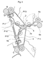
- Fig. 3 shows a more detailed sectional view of the invention dynamic switch unit 2 with profiles P13 up to P17.
- the deflecting element which can be pivoted about the axis of rotation 2b 2a is shown in the two positions b and c, the Deflection element 2a in position b with a solid Line and in position c with a dash-dotted line is drawn.
- the deflection element 2a is in the Position b is an arc from area A. distracted to area B. However, the deflection element is located 2a in position c, the area A originating sheets transported to area C.
- arrangement shown is a pure switch arrangement, since they do not have any necessary for the turning function Reversal area. Both area B and area C are used for the further transport of the sheets.
- the dash-dotted Lines show some of the profiles, e.g. the profiles P13, P14 and P16, when swung out.
- Fig. 4 shows a more detailed sectional view of the invention passive switch unit 4.
- the passive switch unit 4 is formed by three profiles P18, P19 and P20.
- Profile P18 and profile P19 each form together with the profile P20 one up and one left path w1 or w2 extending upward to the right.
- the pointy tapered wedge 4a is firmly connected to the profile P20, the tapered decision edge of the wedge 4a in essentially directed towards the path coming from below is.
- Tangent T1 along the left side Path and the tangent T2 along the right side directed path span an angle with a bisector W on.
- the tapered wedge 4a of the passive Switch unit 4 is from the direction of the bisector W bent away.
- This special shape of the passive switch unit 4 a sheet of paper offers two options Switch unit 4 to go through.
- a from below along the The arrow R3 brought forward passes the switch unit 4 along the path to the top left that leads through the Arrow R1 is indicated.
- the one to the top right directional path can only be traversed by a paper through the top right along arrow R2 this path is introduced.
- the sheet of paper brought up from the top right can be S-shaped Area of this path compared to that of the bisector W bent wedge 4a with bulge 18 happen easily.
- Fig. 5 shows a sectional view of a device with a housing 30 built-in turning arrangement according to the invention, which the Contains profiles P21 to P25.
- the device is e.g. an electrophotographic printer.
- the built-in Reversing arrangement enables paper output with either Face up or face down.
- For this paper is first through a channel along arrow R1 introduced to the turning arrangement according to the invention.
- the Paper then passes through area A and then varies depending on the position of the active switch unit 2 along the path transported to the area B from which it is along the Arrow R2 e.g. is supplied to a post-processing unit.
- a post-processing unit e.g. the picture side of the single sheet up.
- the active switch unit 2 is in its other position switched, so that along the arrow Rl over the Area A led arch deflected to the left, crossed the path ac and the passive switch unit 4 in order finally to get to area C, where it initially is pulled in and then ejected and finally is transported along the path cb to the area B. Now the picture side of the paper sheet is at the bottom, see above that the paper in the reversed state of the post-processing unit is fed.
- All path lengths along the path elements between successive ones Roller pairs must be in the inventive Arrangements should be shorter than the length of the items to be transported Sheets of paper in the transport direction.
- Each pair of rollers is a position detector e.g. B. in the form of a light barrier assigned so that it can always be monitored where a Paper sheet is located. This will make an appropriate ad possible for the user who occurs at an Then jam the paper path at the appropriate location by swinging down a profile can open the paper jam to fix. Swung-out profiles P are shown in FIG. 5 shown in dash-dotted lines.
Landscapes
- Engineering & Computer Science (AREA)
- Mechanical Engineering (AREA)
- Separation, Sorting, Adjustment, Or Bending Of Sheets To Be Conveyed (AREA)
Description
- Fig. 1
- eine Schnittansicht einer ersten Ausführungsform der erfindungsgemäßen Wendeanordnung zeigt;
- Fig. 2
- eine Schnittansicht einer zweiten Ausführungsform der erfindungsgemäßen Wendeanordnung zeigt;
- Fig. 3
- eine Schnittansicht zur Veranschaulichung der Funktionsweise eines ersten Elements der erfindungsgemäßen Wendeanordnung ist;
- Fig. 4
- eine Schnittansicht zur Veranschaulichung der Funktionsweise eines zweiten Elements der erfindungsgemäßen Wendeanordnung ist; und
- Fig. 5
- eine Schnittansicht der in ein Gerät eingebauten erfindungsgemäßen Wendeanordnung zeigt.
- P1 bis P25
- Profile
- G
- Drehachse
- A
- erster Bereich oder Herkunftsbereich
- B
- zweiter Bereich oder Zielbereich
- C
- dritter Bereich oder Umkehrbereich
- ab
- erster Pfad
- ac
- zweiter Pfad
- cb, bc
- dritter Pfad
- 6a, 6b
- Walzenpaar
- 10a, 10b
- Walzenpaar
- 14a, 14b
- Walzenpaar
- 8, 12, 16
- Positionsdetektor
- 2
- aktive oder dynamische Weicheneinheit
- 2a
- Umlenkelement
- 2b
- Drehachse
- 4
- passive oder statische Weicheneinheit
- 4a
- spitz zulaufender Keil
- Kb, Kc
- Keilfläche
- 20, 22
- Stege
- Pa, Pb, Pc
- Konturen
- b
- erste Position
- c
- zweite Position
- T1, T2
- Tangente
- R1, R2, R3
- Pfeil
- 18
- Ausbuchtung
- 30
- Gehäuse
Claims (10)
- Wendeanordnung in einem Führungssystem für blattförmiges Material, insbesondere für Einzelblätter aus Papier, in einem Einzelblattdrucker oder Kopierer, mit einem Papierführungssystem mit Weichenelementen, wobei aus einem ersten Bereich (A) des Führungssystems herantransportierte Bögen des blattförmigen Materials mittels einer aktiven Weicheneinheit (2) in einen von zwei möglichen Pfaden (ab oder ac) abzweigbar sind,die Bögen entlang des ersten Pfades (ab) unmittelbar einem zweiten Bereich (B) des Führungssystems zuführbar sind,und die Bögen entlang des zweiten Pfades (ac) durch eine passive Weicheneinheit (4) zunächst einem dritten Bereich (C) des Führungssystems zuführbar sind, in welchem die Transportrichtung der zugeführten Bögen mittels einer Umkehreinheit (10) umkehrbar ist,um sie im dritten Bereich (C) in umgekehrter Richtung entlang eines dritten Pfades (cb) durch die passive Weicheneinheit (4) dem zweiten Bereich (B) des Führungssystems zuzuführen,wobei die aktive Weicheneinheit (2) ein angesteuertes Umlenkelement (2a) enthält, welches die aus dem ersten Bereich (A) herantransportierten Bögen je nach Ansteuerung in den ersten Pfad (ab) oder in den zweiten Pfad (ac) umlenkt,die passive Weicheneinheit (4) Bögen nur entweder entlang des zweiten Pfades (ac) vom ersten Bereich (A) zum dritten Bereich (C) oder entlang des dritten Pfades (cb) vom dritten Bereich (C) zum zweiten Bereich (B) hindurchtreten läßt,und wobei die passive Weicheneinheit (4) in dem Abschnitt des Führungssystemes, in dem der zweite Pfad (ac) und der dritte Pfad (cb) zusammenlaufen, einen feststehenden spitz zulaufenden Keil (4a) mit einer quer zur Transportrichtung der Bögen verlaufenden Entscheidungskante hat, der bezogen auf die Längsrichtung des dritten Pfades (cb) derart geneigt verläuft, daß die Spaltbreite des dritten Pfades (cb) im Bereich des Keiles (4a) in Richtung der Entscheidungskante gesehen zunimmt und der Keil (4a) in den zweiten Pfad (ac) ragt, dadurch gekennzeichnet,daß der zweite Pfad (ac) im Bereich des spitz zulaufenden Keils (4a) eine Ausbuchtung (18) hat, die mit dem Keil (4a) einen im Querschnitt quer zur Transportrichtung gesehen S-förmig verlaufenden Abschnitt definiert, mit dem der zweite Pfad (ac) in den dritten Pfad (cb) mündet.
- Wendeanordnung nach Anspruch 1, dadurch gekennzeichnet, daß das Strangprofil (P1; P14; P18; P21) des Pfades (ac) in dem zu dem weggebogenen Keil (4a) gegenüberliegenden Bereich gewölbt ist, so daß die Spaltbreite (s) des Pfades (ac) zwischen dem Strangprofil (P1; P14; P18; P21) und dem weggebogenen Keil (4a) im wesentlichen konstant ist.
- Wendeanordnung nach Anspruch 1 oder 2, dadurch gekennzeichnet, daß die Umkehreinheit (10) aus einem Paar gegenläufiger Walzen (10a, 10b) mit einem Einzugsbereich zwischen den Walzen und aus einem Positionsdetektor (8) zum Erfassen der Einzugsposition der Bögen besteht, wobei das Walzenpaar (10a, 10b) in zwei Richtungen zum Einziehen und zum Ausstoßen der Bögen in umgekehrter Richtung betrieben werden kann.
- Wendeanordnung nach einem der Ansprüche 1, 2 oder 3, dadurch gekennzeichnet, daß die Pfade (ab, ac, cb) sowie die aktive als auch die passive Weicheneinheit (2, 4) durch paarweise gegenüberliegende Strangprofile (P1-P5; P6-P12; P13-P17) festgelegt sind, die zwischen zwei parallel angeordneten Platten befestigt sind.
- Wendeanordnung nach einem der Ansprüche 1 bis 4, dadurch gekennzeichnet, daß jeweils eines der paarweise gegenüberliegenden Strangprofile (P1-P5; P6-P12; P13-P17) um eine senkrecht zur Transportrichtung der Bögen und in der Ebene der Bögen verlaufende Drehachse (G) schwenkbar angeordnet und zwischen den beiden parallel angeordneten Platten in der den jeweiligen Pfad festlegenden Position verriegelbar ist.
- Wendeanordnung nach einem der Ansprüche 1 bis 5, dadurch gekennzeichnet, daß in jedem der Bereiche (A, B, C) ein Walzenpaar (6a, 6b, 10a, 10b, 14a, 14b) für den Transport der Bögen mit einem dem jeweiligen Walzenpaar zugeordneten Positionsdetektor (8, 12, 16) zum Erfassen der Position der Bögen angeordnet ist, wobei die Weglänge entlang der Pfade (ab, ac, cb) zwischen den jeweiligen Walzenpaaren der Bereiche (A, B, C) kürzer als die Länge der zu transportierenden Bögen ist.
- Wendeanordnung nach einem der Ansprüche 1 bis 6, dadurch gekennzeichnet, daß die Konturen (Pa, Pb, Pc) der Strangprofile in den Bereichen (A, B, C) dicht an den Konturen der jeweiligen Walzen anliegen.
- Wendeanordnung nach Anspruch 7, dadurch gekennzeichnet, daß sich die Konturen der Strangprofile (Pc) und der Walzen (10a, 10b) zum Teil überlagern und Vorsprünge der Strangprofile in Vertiefungen der Walzen und/oder Vorsprünge der Walzen in Vertiefungen der Strangprofile eingreifen.
- Wendeanordnung nach einem der Ansprüche 1 bis 8, dadurch gekennzeichnet, daß das Umlenkelement (2a) der aktiven Weicheneinheit (2) im wesentlichen keilförmig ausgebildet ist, wobei die spitz zulaufende Entscheidungskante des Keils zu dem Pfad für die an die Wendeanordnung herantransportierten Bögen hin gerichtet ist und der Keil im Bereich seiner Basis um eine senkrecht zur Transportrichtung der Bögen und parallel zur Ebene der Bögen verlaufende Drehachse (2b) zwischen einer ersten Position (b) und einer zweiten Position (c) schwenkbar angeordnet ist, wobei die Basis des Keils senkrecht zur Drehachse (2b) des Keils den Bereich zwischen den Eintrittsbereichen in die beiden Pfade (ab, ac) für die zum zweiten Bereich (B) bzw. zum dritten Bereich (C) abtransportierten Bögen abschirmt und die Bögen je nach der Position (b oder c) des Umlenkelements (2) entlang einer Keilfläche (Kb bzw. Kc) in den Pfad (ab bzw. ac) gelenkt werden.
- Passive Weicheneinheit zum Umlenken von Bögen blattförmigen Materials in einem aus Pfaden (wl, w2) gebildeten Führungssystem, wobei die Weicheneinheit (4) in dem Abschnitt des Führungssystemes, in dem die beiden Pfad (w1, w2) zusammenlaufen, einen feststehenden spitz zulaufenden Keil (4a) mit einer quer zur Transportrichtung der Bögen verlaufenden Entscheidungskante hat, der bezogen auf die Längsrichtung des einen Pfades (w1) derart geneigt verläuft, daß die Spaltbreite dieses Pfades (wl) im Bereich des Keiles (4a) in Richtung der Entscheidungskante gesehen zunimmt und der Keil (4a) in den weiteren Pfad (w2) ragt, dadurch gekennzeichnet,
daß der weitere Pfad (w2) im Bereich des spitz zulaufenden Keils (4a) eine Ausbuchtung (18) hat, die mit dem Keil (4a) einen im Querschnitt quer zur Transportrichtung gesehen S-förmig verlaufenden Abschnitt definiert, mit dem der weitere Pfad (w2) in den einen Pfad (wl) mündet.
Applications Claiming Priority (3)
| Application Number | Priority Date | Filing Date | Title |
|---|---|---|---|
| DE19643666 | 1996-10-22 | ||
| DE19643666 | 1996-10-22 | ||
| PCT/DE1997/002431 WO1998017570A1 (de) | 1996-10-22 | 1997-10-20 | Wendeanordnung für blattförmiges material |
Publications (2)
| Publication Number | Publication Date |
|---|---|
| EP0934224A1 EP0934224A1 (de) | 1999-08-11 |
| EP0934224B1 true EP0934224B1 (de) | 2001-06-13 |
Family
ID=7809513
Family Applications (1)
| Application Number | Title | Priority Date | Filing Date |
|---|---|---|---|
| EP97947696A Expired - Lifetime EP0934224B1 (de) | 1996-10-22 | 1997-10-20 | Wendeanordnung für blattförmiges material |
Country Status (4)
| Country | Link |
|---|---|
| US (1) | US6129349A (de) |
| EP (1) | EP0934224B1 (de) |
| DE (2) | DE59703823D1 (de) |
| WO (1) | WO1998017570A1 (de) |
Cited By (2)
| Publication number | Priority date | Publication date | Assignee | Title |
|---|---|---|---|---|
| DE102004031172A1 (de) * | 2004-06-28 | 2006-01-12 | Eastman Kodak Co. | Vorrichtung zur Handhabung eines Bedruckstoffes |
| DE102011000785A1 (de) * | 2011-02-17 | 2012-08-23 | Wincor Nixdorf International Gmbh | Vorrichtung zum Entwerten von Schecks |
Families Citing this family (13)
| Publication number | Priority date | Publication date | Assignee | Title |
|---|---|---|---|---|
| US6328303B1 (en) * | 1997-11-13 | 2001-12-11 | Canon Kabushiki Kaisha | Image forming apparatus with built-in surface reverse path |
| US6398212B1 (en) | 1998-12-18 | 2002-06-04 | Canon Kabushiki Kaisha | Sheet surface reversing device and image forming apparatus having the same |
| DE20006890U1 (de) * | 2000-04-14 | 2000-06-21 | NexPress Solutions LLC, Rochester, N.Y. | Drei-Wege-Weiche |
| DE10024206A1 (de) * | 2000-05-17 | 2001-11-22 | Nexpress Solutions Llc | Papierführung |
| JP3805269B2 (ja) * | 2002-03-13 | 2006-08-02 | キヤノン株式会社 | シート案内装置及び該装置を備えた画像形成装置 |
| US7108260B2 (en) * | 2003-12-19 | 2006-09-19 | Palo Alto Research Center Incorporated | Flexible director paper path module |
| US7185888B2 (en) * | 2004-03-29 | 2007-03-06 | Palo Alto Research Center Incorporated | Rotational jam clearance apparatus |
| US7512455B2 (en) * | 2004-03-29 | 2009-03-31 | Palo Alto Research Center Incorporated | Method for self-synchronization of modular production systems |
| US7606632B2 (en) * | 2004-06-16 | 2009-10-20 | Cryovac, Inc. | Apparatus for dispensing activated monitoring devices |
| US8172228B2 (en) * | 2009-03-26 | 2012-05-08 | Xerox Corporation | Integrated module |
| CN101987700B (zh) * | 2009-07-31 | 2013-06-05 | 山东新北洋信息技术股份有限公司 | 记录介质翻转机构及使用该机构的记录介质处理装置 |
| DE102009052379A1 (de) | 2009-11-09 | 2011-05-12 | Wincor Nixdorf International Gmbh | Vorrichtung zur Handhabung von Wertscheinen |
| CN102139818B (zh) | 2011-04-13 | 2013-03-06 | 广州广电运通金融电子股份有限公司 | 片状物输送用导向器 |
Family Cites Families (16)
| Publication number | Priority date | Publication date | Assignee | Title |
|---|---|---|---|---|
| JPS5922848A (ja) * | 1982-07-28 | 1984-02-06 | Canon Inc | シ−ト反転装置 |
| GB8315734D0 (en) * | 1983-06-08 | 1983-07-13 | Xerox Corp | Sheet reversing apparatus |
| JPS60137759A (ja) * | 1983-12-27 | 1985-07-22 | Toshiba Corp | 紙葉類の搬送装置 |
| JPS61132578A (ja) * | 1984-11-30 | 1986-06-20 | 京セラ株式会社 | セラミツクのメタライズ法 |
| US4921236A (en) * | 1986-06-05 | 1990-05-01 | Ricoh Company, Ltd. | Recycling automatic document feeder |
| JPH0423888Y2 (de) * | 1986-08-20 | 1992-06-04 | ||
| JPH062552B2 (ja) * | 1986-08-27 | 1994-01-12 | 富士ゼロックス株式会社 | 複写機の紙送り装置 |
| DE3807808A1 (de) * | 1988-03-10 | 1989-09-21 | Philips Patentverwaltung | Bueromaschine, z. b. drucker |
| DE8803496U1 (de) * | 1988-03-15 | 1988-05-11 | Nixdorf Computer Ag, 4790 Paderborn | Drucker mit einer Mehrzahl von Ausgabekanälen für Aufzeichnungsträger |
| DE3914183A1 (de) * | 1988-05-01 | 1989-11-09 | Minolta Camera Kk | Transporteinrichtung fuer papierblaetter |
| US5014976A (en) * | 1990-04-04 | 1991-05-14 | Xerox Corporation | Exit roller shield for duplex printing |
| JPH05310356A (ja) * | 1992-05-07 | 1993-11-22 | Fuji Xerox Co Ltd | 用紙反転装置 |
| US5303017A (en) * | 1993-05-07 | 1994-04-12 | Xerox Corporation | Print skip avoidance for on-line compiling |
| US5415391A (en) * | 1994-05-31 | 1995-05-16 | Xerox Corporation | Low cost compact inverter |
| US5449164A (en) * | 1994-08-29 | 1995-09-12 | Xerox Corporation | Sheet inverter apparatus |
| US5629762A (en) * | 1995-06-07 | 1997-05-13 | Eastman Kodak Company | Image forming apparatus having a duplex path and/or an inverter |
-
1997
- 1997-10-20 US US09/284,921 patent/US6129349A/en not_active Expired - Lifetime
- 1997-10-20 DE DE59703823T patent/DE59703823D1/de not_active Expired - Fee Related
- 1997-10-20 EP EP97947696A patent/EP0934224B1/de not_active Expired - Lifetime
- 1997-10-20 WO PCT/DE1997/002431 patent/WO1998017570A1/de not_active Ceased
- 1997-10-20 DE DE19781155T patent/DE19781155D2/de not_active Ceased
Cited By (3)
| Publication number | Priority date | Publication date | Assignee | Title |
|---|---|---|---|---|
| DE102004031172A1 (de) * | 2004-06-28 | 2006-01-12 | Eastman Kodak Co. | Vorrichtung zur Handhabung eines Bedruckstoffes |
| DE102011000785A1 (de) * | 2011-02-17 | 2012-08-23 | Wincor Nixdorf International Gmbh | Vorrichtung zum Entwerten von Schecks |
| US9179026B2 (en) | 2011-02-17 | 2015-11-03 | Wincor Nixdorf International Gmbh | Device for cancelling checks |
Also Published As
| Publication number | Publication date |
|---|---|
| DE59703823D1 (de) | 2001-07-19 |
| EP0934224A1 (de) | 1999-08-11 |
| WO1998017570A1 (de) | 1998-04-30 |
| DE19781155D2 (de) | 1999-10-28 |
| US6129349A (en) | 2000-10-10 |
Similar Documents
| Publication | Publication Date | Title |
|---|---|---|
| WO1998017570A1 (de) | Wendeanordnung für blattförmiges material | |
| DE69425006T2 (de) | Vorrichtung zum Fördern von Bogen mit Rollen | |
| DE3941315A1 (de) | Vorrichtung zum vermeiden einer schieflage geschnittener papierbogen | |
| EP0363915B1 (de) | Falzmaschine, insbesondere Stauchfalzmaschine | |
| DE2731575C3 (de) | Verfahren und Anordnung zum wahlweisen seitlichen Verschieben von in einer vorgegebenen Richtung zu fördernden Blättern | |
| DE3036642A1 (de) | Transportvorrichtung fuer papierbahnen in buchungsmaschinen | |
| DE3872158T2 (de) | Vorrichtung zum transportieren von boegen. | |
| EP0379712B1 (de) | Vorrichtung zum zickzackförmigen Falten einer Papierbahn | |
| DE3244422A1 (de) | Schneidevorrichtung fuer bogen sowie hefte mit mindestens einem rotierenden schneidmesser und einer foerdervorrichtung | |
| DE3808477A1 (de) | Vorrichtung zum glaetten von einzelblaettern in nichtmechanischen druck- und kopiereinrichtungen | |
| DE1230439B (de) | Vorrichtung zum Zufuehren von zu bedruckendem Band, insbesondere zu Druckmaschinen | |
| EP0507306B1 (de) | Riementransportsystem | |
| DE60001380T2 (de) | Automatische Papierbahneinzugsvorrichtung | |
| EP1976788A1 (de) | Vorrichtung zum umlenken von blattgut | |
| EP0699169B1 (de) | Andruckrollenanordnung für eine stapeleinrichtung eines druck- oder kopiergerätes | |
| DE69812244T2 (de) | Sektionale Rolleneinheit für Förderlinien | |
| EP1247775B1 (de) | Falzvorrichtung für Druckbogen | |
| WO1998018055A1 (de) | Klappenanordnung für den zugriff zu einem papierweg von einzelblattdruckern und -kopierern | |
| DE19960347C2 (de) | Vorrichtung zum Ablenken eines Schuppenstroms auf einem Rolltisch | |
| DE8915626U1 (de) | Vorrichtung zum schwebenden Führen von zu fördernden Materialbahnen oder Materialbogen | |
| DE19533770C2 (de) | Führungsvorrichtung für lichtempfindliches Material | |
| DE69214861T2 (de) | Fixierwalze und diese nutzende Bildfixiervorrichtung | |
| CH634528A5 (en) | Web-fed rotary printing machine | |
| EP0091065B1 (de) | Vorrichtung zum getrennten Führen von zwei Schichtträgerblättern durch ein Bad eines Diffusionsentwicklungsgerätes | |
| DE69630850T2 (de) | Filmzufuhrvorrichtung |
Legal Events
| Date | Code | Title | Description |
|---|---|---|---|
| PUAI | Public reference made under article 153(3) epc to a published international application that has entered the european phase |
Free format text: ORIGINAL CODE: 0009012 |
|
| 17P | Request for examination filed |
Effective date: 19990519 |
|
| AK | Designated contracting states |
Kind code of ref document: A1 Designated state(s): DE FR GB |
|
| GRAG | Despatch of communication of intention to grant |
Free format text: ORIGINAL CODE: EPIDOS AGRA |
|
| GRAG | Despatch of communication of intention to grant |
Free format text: ORIGINAL CODE: EPIDOS AGRA |
|
| GRAH | Despatch of communication of intention to grant a patent |
Free format text: ORIGINAL CODE: EPIDOS IGRA |
|
| 17Q | First examination report despatched |
Effective date: 20001017 |
|
| GRAH | Despatch of communication of intention to grant a patent |
Free format text: ORIGINAL CODE: EPIDOS IGRA |
|
| GRAA | (expected) grant |
Free format text: ORIGINAL CODE: 0009210 |
|
| AK | Designated contracting states |
Kind code of ref document: B1 Designated state(s): DE FR GB |
|
| PG25 | Lapsed in a contracting state [announced via postgrant information from national office to epo] |
Ref country code: GB Free format text: LAPSE BECAUSE OF FAILURE TO SUBMIT A TRANSLATION OF THE DESCRIPTION OR TO PAY THE FEE WITHIN THE PRESCRIBED TIME-LIMIT Effective date: 20010613 Ref country code: FR Free format text: LAPSE BECAUSE OF FAILURE TO SUBMIT A TRANSLATION OF THE DESCRIPTION OR TO PAY THE FEE WITHIN THE PRESCRIBED TIME-LIMIT Effective date: 20010613 |
|
| REF | Corresponds to: |
Ref document number: 59703823 Country of ref document: DE Date of ref document: 20010719 |
|
| GBV | Gb: ep patent (uk) treated as always having been void in accordance with gb section 77(7)/1977 [no translation filed] |
Effective date: 20010613 |
|
| EN | Fr: translation not filed | ||
| PLBE | No opposition filed within time limit |
Free format text: ORIGINAL CODE: 0009261 |
|
| STAA | Information on the status of an ep patent application or granted ep patent |
Free format text: STATUS: NO OPPOSITION FILED WITHIN TIME LIMIT |
|
| 26N | No opposition filed | ||
| PGFP | Annual fee paid to national office [announced via postgrant information from national office to epo] |
Ref country code: DE Payment date: 20071218 Year of fee payment: 11 |
|
| PG25 | Lapsed in a contracting state [announced via postgrant information from national office to epo] |
Ref country code: DE Free format text: LAPSE BECAUSE OF NON-PAYMENT OF DUE FEES Effective date: 20090501 |