EP0925919A2 - Tintenstrahldruckapparat - Google Patents
Tintenstrahldruckapparat Download PDFInfo
- Publication number
- EP0925919A2 EP0925919A2 EP98310743A EP98310743A EP0925919A2 EP 0925919 A2 EP0925919 A2 EP 0925919A2 EP 98310743 A EP98310743 A EP 98310743A EP 98310743 A EP98310743 A EP 98310743A EP 0925919 A2 EP0925919 A2 EP 0925919A2
- Authority
- EP
- European Patent Office
- Prior art keywords
- ink
- treatment liquid
- pigment
- dye
- mixed
- Prior art date
- Legal status (The legal status is an assumption and is not a legal conclusion. Google has not performed a legal analysis and makes no representation as to the accuracy of the status listed.)
- Granted
Links
- 238000007641 inkjet printing Methods 0.000 title claims description 60
- 239000000976 ink Substances 0.000 claims abstract description 770
- 239000007788 liquid Substances 0.000 claims abstract description 425
- 238000007639 printing Methods 0.000 claims abstract description 397
- 239000000049 pigment Substances 0.000 claims abstract description 310
- 238000002156 mixing Methods 0.000 claims abstract description 43
- 239000002270 dispersing agent Substances 0.000 claims abstract description 35
- 238000004040 coloring Methods 0.000 claims description 84
- 239000000463 material Substances 0.000 claims description 84
- 230000035515 penetration Effects 0.000 claims description 82
- 239000006185 dispersion Substances 0.000 claims description 58
- 238000000034 method Methods 0.000 claims description 46
- 239000000203 mixture Substances 0.000 claims description 21
- 239000002245 particle Substances 0.000 claims description 17
- 125000001424 substituent group Chemical group 0.000 claims description 12
- CIUQDSCDWFSTQR-UHFFFAOYSA-N [C]1=CC=CC=C1 Chemical compound [C]1=CC=CC=C1 CIUQDSCDWFSTQR-UHFFFAOYSA-N 0.000 claims description 8
- 125000004429 atom Chemical group 0.000 claims description 8
- QGZKDVFQNNGYKY-UHFFFAOYSA-O Ammonium Chemical compound [NH4+] QGZKDVFQNNGYKY-UHFFFAOYSA-O 0.000 claims description 7
- 229910052799 carbon Inorganic materials 0.000 claims description 7
- 229910052783 alkali metal Inorganic materials 0.000 claims description 4
- 150000001340 alkali metals Chemical class 0.000 claims description 4
- 239000003795 chemical substances by application Substances 0.000 claims description 4
- 229910006074 SO2NH2 Inorganic materials 0.000 claims description 3
- 125000004435 hydrogen atom Chemical group [H]* 0.000 claims description 3
- 125000004432 carbon atom Chemical group C* 0.000 claims 4
- 238000009877 rendering Methods 0.000 claims 1
- 125000000565 sulfonamide group Chemical group 0.000 claims 1
- 238000006243 chemical reaction Methods 0.000 abstract description 41
- 238000002791 soaking Methods 0.000 abstract description 17
- 239000007795 chemical reaction product Substances 0.000 description 46
- 230000000694 effects Effects 0.000 description 45
- 238000010276 construction Methods 0.000 description 37
- 235000019241 carbon black Nutrition 0.000 description 30
- QFXZANXYUCUTQH-UHFFFAOYSA-N ethynol Chemical compound OC#C QFXZANXYUCUTQH-UHFFFAOYSA-N 0.000 description 29
- 239000006229 carbon black Substances 0.000 description 28
- 230000000149 penetrating effect Effects 0.000 description 24
- 230000007903 penetration ability Effects 0.000 description 17
- XLYOFNOQVPJJNP-UHFFFAOYSA-N water Substances O XLYOFNOQVPJJNP-UHFFFAOYSA-N 0.000 description 16
- MTHSVFCYNBDYFN-UHFFFAOYSA-N diethylene glycol Chemical compound OCCOCCO MTHSVFCYNBDYFN-UHFFFAOYSA-N 0.000 description 15
- PEDCQBHIVMGVHV-UHFFFAOYSA-N Glycerine Chemical compound OCC(O)CO PEDCQBHIVMGVHV-UHFFFAOYSA-N 0.000 description 14
- 125000000129 anionic group Chemical group 0.000 description 14
- 125000002091 cationic group Chemical group 0.000 description 12
- 150000003254 radicals Chemical class 0.000 description 10
- 239000004094 surface-active agent Substances 0.000 description 10
- -1 alkyl radical Chemical group 0.000 description 8
- 239000002344 surface layer Substances 0.000 description 8
- 230000000052 comparative effect Effects 0.000 description 7
- 239000012847 fine chemical Substances 0.000 description 7
- 235000011187 glycerol Nutrition 0.000 description 7
- 230000006872 improvement Effects 0.000 description 7
- 229920000642 polymer Polymers 0.000 description 7
- 239000000872 buffer Substances 0.000 description 6
- 239000010419 fine particle Substances 0.000 description 6
- 239000011345 viscous material Substances 0.000 description 6
- 239000000835 fiber Substances 0.000 description 5
- 230000015654 memory Effects 0.000 description 5
- 239000000126 substance Substances 0.000 description 5
- 230000001629 suppression Effects 0.000 description 5
- 238000011156 evaluation Methods 0.000 description 4
- 238000002474 experimental method Methods 0.000 description 4
- 230000006870 function Effects 0.000 description 4
- 230000036632 reaction speed Effects 0.000 description 4
- QTBSBXVTEAMEQO-UHFFFAOYSA-N Acetic acid Chemical compound CC(O)=O QTBSBXVTEAMEQO-UHFFFAOYSA-N 0.000 description 3
- 230000015572 biosynthetic process Effects 0.000 description 3
- 230000000740 bleeding effect Effects 0.000 description 3
- 230000015556 catabolic process Effects 0.000 description 3
- 239000003086 colorant Substances 0.000 description 3
- 230000000875 corresponding effect Effects 0.000 description 3
- 238000006731 degradation reaction Methods 0.000 description 3
- 230000008021 deposition Effects 0.000 description 3
- LYCAIKOWRPUZTN-UHFFFAOYSA-N Ethylene glycol Chemical compound OCCO LYCAIKOWRPUZTN-UHFFFAOYSA-N 0.000 description 2
- VEXZGXHMUGYJMC-UHFFFAOYSA-N Hydrochloric acid Chemical compound Cl VEXZGXHMUGYJMC-UHFFFAOYSA-N 0.000 description 2
- 241000872198 Serjania polyphylla Species 0.000 description 2
- CDBYLPFSWZWCQE-UHFFFAOYSA-L Sodium Carbonate Chemical compound [Na+].[Na+].[O-]C([O-])=O CDBYLPFSWZWCQE-UHFFFAOYSA-L 0.000 description 2
- 241000610628 Trichoptilium incisum Species 0.000 description 2
- RWZYAGGXGHYGMB-UHFFFAOYSA-N anthranilic acid Chemical compound NC1=CC=CC=C1C(O)=O RWZYAGGXGHYGMB-UHFFFAOYSA-N 0.000 description 2
- 230000005587 bubbling Effects 0.000 description 2
- 150000001721 carbon Chemical group 0.000 description 2
- 230000002596 correlated effect Effects 0.000 description 2
- 238000010586 diagram Methods 0.000 description 2
- 238000005516 engineering process Methods 0.000 description 2
- 238000005243 fluidization Methods 0.000 description 2
- 230000001788 irregular Effects 0.000 description 2
- 239000010410 layer Substances 0.000 description 2
- 238000005259 measurement Methods 0.000 description 2
- 230000007246 mechanism Effects 0.000 description 2
- 238000012986 modification Methods 0.000 description 2
- 230000004048 modification Effects 0.000 description 2
- 230000003287 optical effect Effects 0.000 description 2
- 230000008569 process Effects 0.000 description 2
- 239000000047 product Substances 0.000 description 2
- 239000011347 resin Substances 0.000 description 2
- 229920005989 resin Polymers 0.000 description 2
- 238000004513 sizing Methods 0.000 description 2
- 239000000779 smoke Substances 0.000 description 2
- 239000002904 solvent Substances 0.000 description 2
- 238000003756 stirring Methods 0.000 description 2
- 238000012360 testing method Methods 0.000 description 2
- COBPKKZHLDDMTB-UHFFFAOYSA-N 2-[2-(2-butoxyethoxy)ethoxy]ethanol Chemical compound CCCCOCCOCCOCCO COBPKKZHLDDMTB-UHFFFAOYSA-N 0.000 description 1
- BJVVUENRMAKDOD-UHFFFAOYSA-N CO.CO.CO.N Chemical compound CO.CO.CO.N BJVVUENRMAKDOD-UHFFFAOYSA-N 0.000 description 1
- OKTJSMMVPCPJKN-UHFFFAOYSA-N Carbon Chemical compound [C] OKTJSMMVPCPJKN-UHFFFAOYSA-N 0.000 description 1
- VEXZGXHMUGYJMC-UHFFFAOYSA-M Chloride anion Chemical compound [Cl-] VEXZGXHMUGYJMC-UHFFFAOYSA-M 0.000 description 1
- DGAQECJNVWCQMB-PUAWFVPOSA-M Ilexoside XXIX Chemical compound C[C@@H]1CC[C@@]2(CC[C@@]3(C(=CC[C@H]4[C@]3(CC[C@@H]5[C@@]4(CC[C@@H](C5(C)C)OS(=O)(=O)[O-])C)C)[C@@H]2[C@]1(C)O)C)C(=O)O[C@H]6[C@@H]([C@H]([C@@H]([C@H](O6)CO)O)O)O.[Na+] DGAQECJNVWCQMB-PUAWFVPOSA-M 0.000 description 1
- WHXSMMKQMYFTQS-UHFFFAOYSA-N Lithium Chemical compound [Li] WHXSMMKQMYFTQS-UHFFFAOYSA-N 0.000 description 1
- IOVCWXUNBOPUCH-UHFFFAOYSA-N Nitrous acid Chemical compound ON=O IOVCWXUNBOPUCH-UHFFFAOYSA-N 0.000 description 1
- ZLMJMSJWJFRBEC-UHFFFAOYSA-N Potassium Chemical compound [K] ZLMJMSJWJFRBEC-UHFFFAOYSA-N 0.000 description 1
- XSQUKJJJFZCRTK-UHFFFAOYSA-N Urea Chemical compound NC(N)=O XSQUKJJJFZCRTK-UHFFFAOYSA-N 0.000 description 1
- 230000005856 abnormality Effects 0.000 description 1
- 238000010521 absorption reaction Methods 0.000 description 1
- 229960000583 acetic acid Drugs 0.000 description 1
- 235000011054 acetic acid Nutrition 0.000 description 1
- 239000002253 acid Substances 0.000 description 1
- 230000009471 action Effects 0.000 description 1
- 125000000217 alkyl group Chemical group 0.000 description 1
- 150000001412 amines Chemical class 0.000 description 1
- 150000001450 anions Chemical class 0.000 description 1
- 238000003491 array Methods 0.000 description 1
- 150000005840 aryl radicals Chemical group 0.000 description 1
- 229960000686 benzalkonium chloride Drugs 0.000 description 1
- CADWTSSKOVRVJC-UHFFFAOYSA-N benzyl(dimethyl)azanium;chloride Chemical compound [Cl-].C[NH+](C)CC1=CC=CC=C1 CADWTSSKOVRVJC-UHFFFAOYSA-N 0.000 description 1
- 239000011230 binding agent Substances 0.000 description 1
- 230000003139 buffering effect Effects 0.000 description 1
- 239000004202 carbamide Substances 0.000 description 1
- ZBNARPCCDMHDDV-UHFFFAOYSA-N chembl1206040 Chemical compound C1=C(S(O)(=O)=O)C=C2C=C(S(O)(=O)=O)C(N=NC3=CC=C(C=C3C)C=3C=C(C(=CC=3)N=NC=3C(=CC4=CC(=CC(N)=C4C=3O)S(O)(=O)=O)S(O)(=O)=O)C)=C(O)C2=C1N ZBNARPCCDMHDDV-UHFFFAOYSA-N 0.000 description 1
- 230000015271 coagulation Effects 0.000 description 1
- 238000005345 coagulation Methods 0.000 description 1
- 230000001276 controlling effect Effects 0.000 description 1
- 230000008878 coupling Effects 0.000 description 1
- 238000010168 coupling process Methods 0.000 description 1
- 238000005859 coupling reaction Methods 0.000 description 1
- 238000001514 detection method Methods 0.000 description 1
- 239000012954 diazonium Substances 0.000 description 1
- IJGRMHOSHXDMSA-UHFFFAOYSA-O diazynium Chemical compound [NH+]#N IJGRMHOSHXDMSA-UHFFFAOYSA-O 0.000 description 1
- 238000007599 discharging Methods 0.000 description 1
- 238000001879 gelation Methods 0.000 description 1
- WGCNASOHLSPBMP-UHFFFAOYSA-N hydroxyacetaldehyde Natural products OCC=O WGCNASOHLSPBMP-UHFFFAOYSA-N 0.000 description 1
- 230000002452 interceptive effect Effects 0.000 description 1
- 229910052744 lithium Inorganic materials 0.000 description 1
- 238000004519 manufacturing process Methods 0.000 description 1
- 125000001624 naphthyl group Chemical group 0.000 description 1
- 150000002825 nitriles Chemical class 0.000 description 1
- 230000003647 oxidation Effects 0.000 description 1
- 238000007254 oxidation reaction Methods 0.000 description 1
- 230000001590 oxidative effect Effects 0.000 description 1
- AKTJDQZOTDDMKB-UHFFFAOYSA-N oxirane;2,4,7,9-tetramethyldec-5-yne-4,7-diol Chemical compound C1CO1.CC(C)CC(C)(O)C#CC(C)(O)CC(C)C AKTJDQZOTDDMKB-UHFFFAOYSA-N 0.000 description 1
- 230000002093 peripheral effect Effects 0.000 description 1
- 229910052700 potassium Inorganic materials 0.000 description 1
- 239000011591 potassium Substances 0.000 description 1
- 238000002360 preparation method Methods 0.000 description 1
- 230000002265 prevention Effects 0.000 description 1
- 230000001737 promoting effect Effects 0.000 description 1
- 230000001846 repelling effect Effects 0.000 description 1
- 239000002002 slurry Substances 0.000 description 1
- 229910052708 sodium Inorganic materials 0.000 description 1
- 239000011734 sodium Substances 0.000 description 1
- 238000003860 storage Methods 0.000 description 1
- 230000032258 transport Effects 0.000 description 1
- ZMANZCXQSJIPKH-UHFFFAOYSA-O triethylammonium ion Chemical compound CC[NH+](CC)CC ZMANZCXQSJIPKH-UHFFFAOYSA-O 0.000 description 1
- ZIBGPFATKBEMQZ-UHFFFAOYSA-N triethylene glycol Chemical compound OCCOCCOCCO ZIBGPFATKBEMQZ-UHFFFAOYSA-N 0.000 description 1
- GETQZCLCWQTVFV-UHFFFAOYSA-N trimethylamine Chemical compound CN(C)C GETQZCLCWQTVFV-UHFFFAOYSA-N 0.000 description 1
- 239000011800 void material Substances 0.000 description 1
- 238000009736 wetting Methods 0.000 description 1
Images


Classifications
-
- B—PERFORMING OPERATIONS; TRANSPORTING
- B41—PRINTING; LINING MACHINES; TYPEWRITERS; STAMPS
- B41J—TYPEWRITERS; SELECTIVE PRINTING MECHANISMS, i.e. MECHANISMS PRINTING OTHERWISE THAN FROM A FORME; CORRECTION OF TYPOGRAPHICAL ERRORS
- B41J2/00—Typewriters or selective printing mechanisms characterised by the printing or marking process for which they are designed
- B41J2/005—Typewriters or selective printing mechanisms characterised by the printing or marking process for which they are designed characterised by bringing liquid or particles selectively into contact with a printing material
- B41J2/01—Ink jet
- B41J2/21—Ink jet for multi-colour printing
- B41J2/2107—Ink jet for multi-colour printing characterised by the ink properties
- B41J2/2114—Ejecting specialized liquids, e.g. transparent or processing liquids
-
- B—PERFORMING OPERATIONS; TRANSPORTING
- B41—PRINTING; LINING MACHINES; TYPEWRITERS; STAMPS
- B41M—PRINTING, DUPLICATING, MARKING, OR COPYING PROCESSES; COLOUR PRINTING
- B41M5/00—Duplicating or marking methods; Sheet materials for use therein
- B41M5/0011—Pre-treatment or treatment during printing of the recording material, e.g. heating, irradiating
- B41M5/0017—Application of ink-fixing material, e.g. mordant, precipitating agent, on the substrate prior to printing, e.g. by ink-jet printing, coating or spraying
-
- C—CHEMISTRY; METALLURGY
- C09—DYES; PAINTS; POLISHES; NATURAL RESINS; ADHESIVES; COMPOSITIONS NOT OTHERWISE PROVIDED FOR; APPLICATIONS OF MATERIALS NOT OTHERWISE PROVIDED FOR
- C09D—COATING COMPOSITIONS, e.g. PAINTS, VARNISHES OR LACQUERS; FILLING PASTES; CHEMICAL PAINT OR INK REMOVERS; INKS; CORRECTING FLUIDS; WOODSTAINS; PASTES OR SOLIDS FOR COLOURING OR PRINTING; USE OF MATERIALS THEREFOR
- C09D11/00—Inks
- C09D11/30—Inkjet printing inks
- C09D11/32—Inkjet printing inks characterised by colouring agents
- C09D11/322—Pigment inks
-
- C—CHEMISTRY; METALLURGY
- C09—DYES; PAINTS; POLISHES; NATURAL RESINS; ADHESIVES; COMPOSITIONS NOT OTHERWISE PROVIDED FOR; APPLICATIONS OF MATERIALS NOT OTHERWISE PROVIDED FOR
- C09D—COATING COMPOSITIONS, e.g. PAINTS, VARNISHES OR LACQUERS; FILLING PASTES; CHEMICAL PAINT OR INK REMOVERS; INKS; CORRECTING FLUIDS; WOODSTAINS; PASTES OR SOLIDS FOR COLOURING OR PRINTING; USE OF MATERIALS THEREFOR
- C09D11/00—Inks
- C09D11/30—Inkjet printing inks
- C09D11/32—Inkjet printing inks characterised by colouring agents
- C09D11/328—Inkjet printing inks characterised by colouring agents characterised by dyes
-
- C—CHEMISTRY; METALLURGY
- C09—DYES; PAINTS; POLISHES; NATURAL RESINS; ADHESIVES; COMPOSITIONS NOT OTHERWISE PROVIDED FOR; APPLICATIONS OF MATERIALS NOT OTHERWISE PROVIDED FOR
- C09D—COATING COMPOSITIONS, e.g. PAINTS, VARNISHES OR LACQUERS; FILLING PASTES; CHEMICAL PAINT OR INK REMOVERS; INKS; CORRECTING FLUIDS; WOODSTAINS; PASTES OR SOLIDS FOR COLOURING OR PRINTING; USE OF MATERIALS THEREFOR
- C09D11/00—Inks
- C09D11/54—Inks based on two liquids, one liquid being the ink, the other liquid being a reaction solution, a fixer or a treatment solution for the ink
Definitions
- the present invention relates generally to an ink-jet printing apparatus and a printing method. More particularly, the invention relates to an ink-jet printing apparatus and a printing method performing printing of characters, images and the like on a printing medium, such as a printing paper, an OHP film and the like using an ink and a liquid which makes a coloring material in the ink insoluble (hereinafter also referred to as a treatment liquid).
- a printing medium such as a printing paper, an OHP film and the like
- a liquid which makes a coloring material in the ink insoluble hereinafter also referred to as a treatment liquid.
- a treatment liquid of this kind reacts with a coloring material contained in an ink, such as a pigment, dye and the like and makes the coloring material insoluble.
- the treatment liquid is ejected overlaying on the portion where the ink is ejected on the printing medium or in the vicinity thereof, for admixing the ink and the treatment liquid to cause reaction.
- the coloring material if the ink is fixed on the surface of the printing medium or with penetrating into the printing medium for achieving water resistance of the printing product.
- the second problem to be encountered in the dye that the inventor has found, is a phenomenon so-called “overflow” or “sweep", and particularly that an edge portion of a printed image becomes blur.
- Figs. 1A to 1D are illustrations for explaining the phenomenon in the predictive manner.
- an ink I d using a dye as a color agent is deposited on the lower penetrative printing medium P such as a plane paper by ejection of the ink through a printing head as an ejecting portion, a part of the ink penetrates into the printing medium and remaining part of the ink is present in a liquid state on the surface of the printing medium P.
- a treatment liquid S is deposited overlaying over the ink I d to cause reaction in a boundary between the treatment liquid S and the ink I d by ejection through the printing head.
- Fig. 1A when an ink I d using a dye as a color agent, is deposited on the lower penetrative printing medium P such as a plane paper by ejection of the ink through a printing head as an ejecting portion, a part of the ink penetrates into the printing medium and remaining part of the ink is present in a liquid state on the surface
- the foregoing phenomenon is caused by flow of a gel form high viscous reaction product in the ink and the treatment liquid for relatively low reaction speed between the dye and the treatment liquid.
- the second problem concerning dye set forth above may not cause in the construction where only dye ink is used and the treatment liquid is not used in printing. Accordingly, in the construction where printing is performed using the dye ink and the treatment liquid which makes the dye ink insoluble, particular technical problem is encountered.
- the pigment ink per se exhibits relatively high OD value as used for printing.
- the OD value of the pigment ink can be improved.
- the pigment has high reaction speed with the treatment liquid.
- the pigment ink there are an ink using a dispersant, such as a resin, a surface-active agent and the like, in order to stabilize dispersion of the pigment in the ink solvent (hereinafter occasionally referred to as dispersant containing pigment ink), and an ink using a self-dispersion type pigment and containing no dispersant (hereinafter occasionally referred to as no dispersant containing pigment ink).
- a dispersant such as a resin, a surface-active agent and the like
- Figs. 2A to 2C are illustrations for predictively explaining this phenomenon.
- the treatment liquid is applied in overlaying manner (see Fig. 2B). Then, production of reaction product is initiated, at first, from the between the ink and the treatment liquid. Then, according to progress of this reaction, radial "soaking out” is caused from substantially circular dot of the reaction product to "blur" the entire circumference of the dot (see Fig. 2C). Such "soaking out” or “blur” appears similar to known feathering. Accordingly, printing quality is lowered.
- the foregoing "soaking out” or “blur” is inferred as the following phenomenon chemically or in micro view.
- the no dispersant containing pigment ink has relatively high reaction speed in reaction with the treatment liquid. Therefore, the dispersed pigment instantly cause dispersion breakage to generate cluster of the reaction product. In conjunction therewith, particulate reaction product is also generated. Then, the particulate reaction product flows out associating with penetration of the treatment liquid into the printing medium to result in the foregoing "soaking out”.
- the applicant of the present invention has proposed use of the ink and the treatment liquid, in which the dye ink and the pigment ink containing the dispersant (Japanese Patent Application Laid-open No. 8-267903).
- Japanese Patent Application Laid-open No. 8-267903 Japanese Patent Application Laid-open No. 8-267903
- the invention disclosed in the above-identified patent application is different from the present invention.
- the present invention has worked out for solving the technical problems set forth above. It is therefore an object of the present invention to provide an ink-jet printing apparatus and a printing method which can solve or improve respective technical problems to be caused upon printing using a dye ink or a pigment ink and a treatment liquid thereof to enable high quality print.
- Another object of the present invention is to provide an ink-jet printing apparatus and a printing method which can speed up a printing speed upon performing printing using the ink and the treatment liquid.
- an ink-jet printing apparatus in which after application of an ink containing a coloring material onto a printing medium, a treatment liquid making the coloring material of the ink insoluble is applied, the ink being a mixed ink, in which a self dispersion type pigment and a dye are mixed, comprising:
- an ink-jet printing apparatus in which after application of an ink containing a coloring material onto a printing medium, a treatment liquid making the coloring material of the ink insoluble is applied, the ink being a mixed ink, in which a self dispersion type pigment and a dye are mixed, comprising:
- an ink-jet printing apparatus employing an ink ejecting portion ejecting an ink and a treatment liquid ejecting portion ejecting a treatment liquid making an ink ejected from the ink ejecting portion insoluble and performing printing by ejecting the treatment liquid after ejection of the ink toward a printing medium, the ink ejecting portion being constituted of at least one mixed ink ejecting portion for ejecting a mixed ink, in which a self dispersion type pigment and dye are mixed, comprising:
- a printing method performing printing by applying a mixed ink, in which a self dispersion type pigment and a dye are mixed, onto a printing medium, and thereafter applying a treatment liquid making the self dispersion type pigment and the dye in the mixed ink insoluble, comprising:
- a printing method performing printing by applying an ink containing a coloring material, and thereafter applying a treatment liquid making the coloring material in the ink insoluble, and the ink being a mixed ink, in which a self dispersion type pigment and a dye are mixed, comprising:
- the mixed ink and the treatment liquid are mixed on the printing medium, "crack” or “soaking out” which could be caused upon printing by using only the pigment ink and the treatment liquid, can be suppressed by presence of the dye simultaneously mixed. Conversely, lowering of an OD value or “overflow” which could be caused upon printing by using only the dye ink and the treatment liquid, can be compensated, or suppressed by presence of the pigment simultaneously mixed.
- the treatment liquid is effective if the penetration speed is higher than or equal to 5.0 (ml/m 2 ⁇ msec 1/2 ) in Ka value by Bristow method.
- the treatment liquid having relatively high penetration ability as the treatment liquid, the reaction product of the pigment or the like and the treatment liquid may also have high penetration ability to achieve high penetration speed as a whole.
- the ink using the dye and the pigment with no dispersant as coloring materials (hereinafter referred to as mixed ink) is applied to the printing medium to form a dot of the reaction product by applying the treatment liquid.
- Figs. 3A to 3C are illustrations for explaining dot formation.
- the mixed ink I m is applied to the printing medium.
- the treatment liquid I s is applied overlaying the mixed ink I m . Therefore, the reaction product generated by reaction of the mixed ink I m and the treatment liquid S is fixed on the surface and inside of the printing medium P to form the dot.
- the ink containing the dye and the pigment without dispersant is used for printing, lowering of OD value to be caused by the dye ink can be compensated by the pigment ink to enhance the OD value. Also, most of the reaction product of the ink as mixed with the treatment liquid may stay in an upper layer of the printing medium to contribute for increasing of the OD value.
- the ink having low penetration speed as the mixed ink is used, even if an interval to following application of the treatment liquid to provide relatively long period for penetration, the amount of the coloring material staying in the surface layer of the printing medium can be made large to further improve the OD value.
- the ink having low penetration speed is used, the problem to be caused in using the dye ink and the pigment ink alone can be solved or reduced.
- the ink having further lower penetration speed increasing of the OD value can be expected.
- so-called feathering can be suppressed.
- the maximum effect of the practical aspect, in which the treatment liquid is applied after application the mixed ink on the printing medium is to solve the problem of "overflow” or “sweep” to be caused by the dye ink and the problem of "soaking out” or “blur” to be caused by the pigment ink are solved or reduced simultaneously.
- the principle achieving these effect can be predicted as follow.
- the treatment liquid is applied.
- the dye and the treatment liquid are reacted to form a gel form high viscous substance.
- the pigment having no dispersant causes breakage of dispersion by reaction with the treatment liquid. It is considered that fine particle of the pigment generated by dispersion breakage is taken into the high viscous substance of the dye reaction product to restrict "soaking out” or “blur” which could be caused by flowing out of the pigment particle.
- the high viscous substance taking in the pigment particles has not so high flow ability in comparison with the reaction product of the dye alone and the treatment liquid. Accordingly, occurrence of "overflow” or "sweep” can be suppressed simultaneously.
- the fine particle of the pigment generated by dispersion breakage are taken in the gel form reaction product so as not to deeply penetrate into the printing medium to bury a gap between fiber of the printing medium in the surface layer. Then, the gel form dye reaction product fills gap between absorbed particles and unevenness of the fiber on the surface of the printing medium. Therefore, irregular reflection of the light can be presented to achieve OD value higher than that achieved when the pigment and the treatment liquid are used.
- an interval from application of the mixed ink to application of the treatment liquid can be shorted in terms of speeding up, a speed of print for the first one printing medium, called as first print, can be increased.
- the foregoing interval can be shortened, down-sizing of the apparatus and lowering of cost can be achieved.
- the order of application of the mixed ink and the treatment liquid onto the printing medium in the practical aspect is basically that the treatment liquid is applied after application of the mixed ink on the printing medium, as set forth above to attain the foregoing effect.
- the mixed ink in the practical aspect is applied in advance of application of the treatment liquid
- number of the mixed ink to be applied is not limited to one droplet as set forth above.
- the mixed ink applied at earlier timing is contains greater proportion of dye than the pigment having no dispersant
- the mixed ink applied later timing contains greater proportion of pigment having no dispersant than the dye. Therefore, upon reaction with the treatment liquid applied later, greater proportion of pigment may react with the treatment liquid to further suppress flow out of the reaction product of the dye and the treatment liquid.
- number of the mixed ink droplet to be applied in advance of application of the treatment liquid is set to three and proportions of the pigment having no dispersant are preferably increased in the mixed ink to be applied in later timing.
- total amount of the applied ink is set to be substantially equal to the case where one droplet is applied.
- the mixed ink is applied with dividing into a plurality of times, even if the amount of the ink becomes smaller according to increasing of number of divided droplets, the foregoing effect can be attained.
- reaction between the mixed ink and the treatment liquid can be caused in various modes.
- mixing of the mixed ink and the treatment liquid becomes insufficient.
- mixing of the pigment or the like and the treatment liquid can be done sufficiently to achieve respective effect of the practical aspect, particularly in suppression of "blur" or "overflow".
- mixture of the mixed ink and the treatment liquid means not only wholly mixing but also partial mixing at the edge portion and so on. Furthermore, “mix” also represents mixing after penetration into the printing medium. Modes of all of these mixing will be defined as “mixing in liquid state”.
- Color (kind), density and number of the ink applied in the practical aspect can be combined arbitrary as long as the foregoing order of application is maintained.
- the kind of the inks of black (Bk), yellow (Y), magenta (M) and cyan (C) inks are used generally. Concerning respective colors, high and low density inks may also be used.
- the mixed ink and the treatment liquid are applied in sequential order.
- the most preferred mode is to use the mixed ink as the black ink. According to this mode, respective effect of the practical aspect, such as increasing of the OD value, suppression of "blur” or “overflow” contributes for printing quality of the characters, such as letters or the like.
- the method applying these mixed ink and so on to the printing medium various method, such as application or directly contacting the ink or the like to the printing medium for application and so on may be encompassed within the scope of the present invention.
- the most preferred mode is the ink-jet printing type employing a printing head. Then, in this case, combination and arrangement of the printing head as the ejecting portion is determined according to combination of application order and kinds of the ink including the treatment liquid.
- the heads for the mixed ink and the treatment liquid are arranged in a direction of relative movement of the printing head with respect to the printing medium, the foregoing sequential order of application becomes possible.
- either case of so-called full-multi type printing head in which the ink ejection openings are arranged within a range corresponding to the entire width of the printing region in the printing medium or serial type printing head performing movement for scanning relative to the printing medium may permit application of the ink and the treatment liquid.
- any known type such as piezo type or the like can be employed.
- Most preferred mode is to generate bubble in the ink or the treatment liquid utilizing thermal energy to eject the ink or the treatment liquid by the pressure of the bubble.
- each printing head a range where the mixed ink and the treatment liquid are ejected to overlay, is normally controlled per pixel forming the printed image or so on.
- the foregoing ink or the like are ejected at the same position in overlaying manner.
- application of the present invention is not limited to the foregoing construction.
- the practical aspect is intended to achieve high speed fixing by employing the treatment liquid having high penetration ability as the treatment liquid in the practical aspect.
- High speed fixing is major construction for achieving speeding up of the printing speed, namely for improvement of throughput.
- By increasing a driving frequency of the printing head or transporting speed of the printing medium direct improvement of throughput becomes possible.
- inconvenience can be caused in subsequent handling.
- non-fixed ink may cause stain of other printing medium.
- a discharge speed of the printing medium after completion of printing which depends on feeding speed of the printing medium or scanning speed of the printing head.
- the feeding speed of the printing medium in printing operation directly corresponds to the discharge speed.
- the scanning speed is directly associated with the discharge speed of the printing medium after completion of printing. Then, the feeding speed of the printing medium and so on is correlated to the ink ejection period for the pixel via solution of printing, namely via dot density. Therefore, in the construction performing printing of one pixel by the ink ejected from a plurality of printing head, when the resolution is considered to be fixed, the ejection period and the feeding speed and so on with respect to the pixel is correlated.
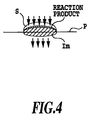
- Fig. 4 shows the case where the mixed ink I m and the treatment liquid S are applied to the printing medium P in the sequential order.
- reaction product starts to be generated between the treatment liquid S and the mixed ink I m contacting at the boundary.
- the penetration speed of the mixture between the treatment liquid S and the mixed ink becomes higher than that of the case where the mixed ink is used alone.
- high speed fixing becomes possible.
- the treatment liquid having high penetration speed particularly when the mixed ink having low penetration speed is used for improving the OD value or the like, relatively high speed fixing can be achieved.
- Still further practical aspect of the present invention relates to order of application of the mixed ink and the treatment liquid. Namely, in the practical aspect, after application of the mixed ink, the treatment liquid is applied, and thereafter, the mixed ink is further applied.
- the practical aspect is particularly effective in improvement of OD value, restriction of "overflow”, “blur” or feathering among the foregoing effects.
- the ink to be applied after application of the treatment liquid is preferred to be the mixed ink set forth above, but can be a self-dispersion type pigment ink or the dye ink.
- an ink-jet printing apparatus applying a first ink containing a coloring material to a printing medium, applying a treatment liquid for making the coloring material in said first ink insoluble and applying a second ink containing a coloring material, wherein
- an ink-jet printing apparatus applying one of a pigment ink containing a pigment as primary coloring material and a dye ink containing a dye as primary coloring material on a printing medium, thereafter applying a treatment liquid making the coloring material in said ink insoluble, and subsequently applying the other of said pigment ink and said dye ink onto said printing medium, comprising:
- an ink-jet printing apparatus having an ink ejecting portion ejecting an ink containing a coloring material and a treatment liquid ejecting portion ejecting a treatment liquid making a coloring material in the ink insoluble for performing printing by ejecting said treatment liquid after ejecting the ink toward a printing medium, said ink ejecting portion including a dye ejecting portion ejecting a dye ink primarily containing a dye as a coloring material and a pigment ejecting portion ejecting a pigment ink primarily containing a pigment as a coloring material, comprising:
- an printing method performing printing by applying an ink containing a coloring material, and thereafter applying a treatment liquid making said coloring material in said ink insoluble, and said ink including a pigment ink containing a pigment as a primary coloring material and a dye ink containing a dye as primary color agent, comprising:
- the treatment liquid is effective when the penetration speed is higher than or equal to 5.0 (ml/m 2 ⁇ msec 1/2 ) in Ka value by Bristow method.
- the dye ink and the pigment ink are mixed on the printing medium, and the treatment liquid is applied to the mixture of the dye ink and the pigment ink to form a dot by the reaction product.
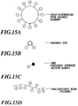
- Figs. 5A to 5D are illustration for explaining formation of dot.
- the dye ink I d is applied to the printing medium.
- the pigment ink I p is applied overlaying the dye ink I d .
- the treatment liquid S is applied to the liquid, in which the dye ink I d and the pigment ink I p are mixed. Therefore, the reaction product generated by reaction of the mixture liquid of the inks and the treatment liquid S is fixed on the surface and inside of the printing medium P to form the dot, as shown in Fig. 5D.
- the dye ink and the pigment ink are mixed on the printing medium, and mixed ink is used for printing. Therefore, lowering of the OD value caused by printing by the dye ink can be compensated by the pigment to enhance the OD value. Furthermore, the reaction product of the treatment liquid and the mixed ink stays in the upper layer portion of the printing medium in large proportion to increase the OD value.
- the dye ink and the pigment ink having low penetration speed are used, if the period to application of the treatment liquid is long to provide a long period for penetration, large proportion of the coloring material may stay in the surface layer of the printing medium to enhance the OD value.
- the problems could be caused when the dye ink and the pigment ink are used alone, can be solved or reduced. Therefore, the dye ink or the pigment ink having further lower penetration speed can be used. Thus, further increasing of the OD value can be expected.
- so-called feathering can be restricted.
- the dye ink and the pigment ink are mixed on the printing medium, and subsequently, the treatment liquid is applied.
- the pigment may react with the treatment liquid to coagulate to generate block of the reaction product.
- the reaction product of the dye reacted with the treatment liquid is fluidized to penetrate therein for fill. Therefore, occurrence of so-called "crack" set forth above can be prevented and restricted.
- the principle achieving these effect can be predicted as follow. Namely, after application of the mixed ink onto the printing medium, the treatment liquid is applied. Then, the dye and the treatment liquid are reacted to form a gel form high viscous substance.
- the pigment having no dispersant causes breakage of dispersion by reaction with the treatment liquid. It is considered that fine particle of the pigment generated by dispersion breakage are taken into the high viscous substance of the dye reaction product to restrict "soaking out” or "blur” which could be caused by flowing out of the pigment particles.
- the high viscous substance absorbing the pigment particle has not so high flow ability in comparison with the reaction product of the dye alone and the treatment liquid.
- the fine particles of the pigment generated by dispersion breakage are taken in the gel form reaction product so as not to deeply penetrate into the printing medium to bury a gap between fiber of the printing medium in the surface layer. Then, the gel form dye reaction product fills gap between absorbed particles and unevenness of the fiber on the surface of the printing medium. Therefore, irregular reflection of the light can be presented to achieve OD value higher than that achieved when the pigment and the treatment liquid are used.
- the phenomenon of "blur” or “overflow” can be caused by reacting the pigment ink or the dye ink with the treatment liquid before penetration into the printing medium. Therefore, in order to suppress occurrence of these phenomena, it becomes necessary to apply the treatment liquid waiting penetration of the dye ink or the like to interfere speeding up of the printing speed.
- the mixed ink per se which is a mixture of the dye and the pigment ink having no dispersant, it becomes unnecessary to set the interval for application of the treatment liquid for waiting penetration of the dye ink or the like into the printing medium. Accordingly, speeding up of the printing speed will not be interfered.
- the OD value can be further improved by using the mixed ink of the practical aspect having relatively low penetration ability so that the coloring material, such as the pigment or the like may stay in the surface layer of the printing medium for a long period.
- an interval from application of the mixed ink to application of the treatment liquid can be shorted in terms of speeding up, a speed of print for the first one printing medium, called as first print, can be increased. Since the foregoing interval can be shortened, down-sizing of the apparatus and lowering of cost can be achieved.
- the order of application of the mixed ink and the treatment liquid onto the printing medium in the practical aspect is basically that the treatment liquid is applied after application of the mixed ink on the printing medium, as set forth above to attain the foregoing effect.
- timing difference of application of the pigment ink and the dye ink can be zero.
- the pigment ink and the dye ink may be applied to the printing medium simultaneously.
- an interval from application of the pigment ink or the like to application of the treatment liquid is desired to include a time for mixing the pigment ink and the dye ink in order to obtain respective effect of the practical aspect set forth above.
- sufficient mixing of the pigment and the like can be caused to achieve the effects of the practical aspect.
- at least the effect of suppression of "blur" or "overflow” can be achieved.
- Color (kind), density and number of the ink applied in the practical aspect can be combined arbitrary as long as the foregoing order of application is maintained.
- the kind of the inks of black (Bk), yellow (Y), magenta (M) and cyan (C) inks are used generally. Concerning respective colors, high and low density inks may also be used.
- the mixed ink and the treatment liquid are applied in sequential order.
- the most preferred mode is to use the mixed ink as the black ink.
- the mixed ink as the black ink.
- the pigment ink and the dye ink have been explained as those containing only pigment and only dye as coloring material components, respectively, various effects set forth above can be achieved not only by the inks set forth above but also by the pigment ink partly containing the dye or the dye ink partly containing pigment.
- the coloring material the ink containing the pigment only or the ink containing the pigment partly containing the dye are defined as "pigment ink containing the pigment as primary coloring material”.
- the ink containing the dye only or the ink containing the dye partly containing the pigment are defined as "dye ink containing the dye as primary coloring material”.
- the method applying these mixed ink and so on to the printing medium various method, such as application or directly contacting the ink or the like to the printing medium for application and so on may be encompassed within the scope of the present invention.
- the most preferred mode is the ink-jet printing type employing a printing head. Then, in this case, combination and arrangement of the printing head as the ejecting portion is determined according to combination of application order and kinds of the ink including the treatment liquid.
- the heads for the mixed ink and the treatment liquid are arranged in a direction of relative movement of the printing head with respect to the printing medium, the foregoing sequential order of application becomes possible.
- each printing head a range where the pigment ink, the dye ink and the treatment liquid are ejected to overlay, is normally controlled per pixel forming the printed image or so on.
- the foregoing ink or the like are ejected at the same position in overlaying manner.
- application of the present invention is not limited to the foregoing construction.
- the effect explained in the fourth practical aspect can be achieved.
- penetration speed can be made higher. Namely, penetration speeds of the pigment ink, the dye ink and the treatment liquid relative to the printing medium being v 1 ⁇ v 3 and v 2 ⁇ v 3 assuming that the penetration speed of the pigment ink is v 1 , the penetration speed of the dye ink is v 2 and the penetration speed of the treatment liquid is v 3 .
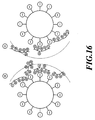
- Fig. 6 shows the case where the pigment ink I p , the dye ink I d and the treatment liquid D are applied on the printing medium P in the sequential order, and shows a condition where the treatment liquid S is applied at a timing where the pigment ink I p and the dye ink I d are not mixed sufficiently.
- the reaction product is generated at the boundary where the treatment liquid S and the dye ink I d contact.
- the penetration speed of the treatment liquid S is high, the reaction product may penetrate at high speed than that when the dye ink is used alone. Since reaction between the dye and the treatment liquid per se is relatively low, the treatment liquid S further penetrates during reaction to also react with the pigment ink I p to make the penetration speed of the reaction product higher. Thus, as a whole, speed can be higher than the penetration speed of the case where the pigment ink and the dye ink are used alone to permit high speed fixing.
- Further practical aspect of the present invention concerns order of application of one of the pigment ink, the dye ink and the treatment liquid. Namely, after application of the dye ink or the pigment ink, the treatment liquid is applied, and subsequently, the other of the pigment ink and the dye ink is applied. More particularly, application is performed in the order of the dye ink, the treatment liquid and then the pigment ink, or in the order of the pigment ink, the treatment ink and then the dye ink.
- the pigment ink, the dye ink and the treatment liquid are mixed on the printing medium, "crack” or “soaking out” which could be caused when printing is performed only by the pigment ink and the treatment liquid can be reduced by presence of the dye ink simultaneously mixed. Conversely, lowering of the OD value or "overflow” which could be caused when printing is performed only by the dye and the treatment liquid, can be compensated by presence of the pigment ink simultaneously mixed and thus can be reduced.
- the reaction product of the pigment ink and the treatment liquid may have high penetration ability to make the penetration speed high as a whole.
- Fig. 7 is a side elevation showing a general construction of one embodiment of a full-line type printing apparatus according to the present invention.
- a shown printing apparatus 1 employs an ink-jet printing type performing printing by ejecting an ink and a treatment liquid by a plurality of full-line type printing heads as an ejecting portion arranged at predetermined positions along a feeding direction of a printing medium (a direction of arrow A in Fig. 1).
- the shown printing apparatus 1 is operated under control by a control circuit shown in Fig. 8, which will be explained later.
- Respective printing heads 101Bk1, 101Bk2, 101S, 101C, 101M and 101Y of a head group 101g can perform printing for a printing paper of maximum A3 size by arranging about 7200 ink ejection openings in a width direction (perpendicular direction of the paper surface of Fig. 7) of the printing paper fed in the direction A in Fig. 7.
- the printing paper 103 is fed in the direction A by rotation of a pair of registration rollers 114 which are driven by a motor for feeding. Then, a tip end of the printing paper 103 is registered as guided by a pair of guide plates 115. Thereafter, the printing paper 103 is fed by a feeding belt 111.
- the feeding belt 111 as an endless belt is held by two rollers 112 and 113. Deflection of the upper side portion of the feeding belt 111 in vertical direction is restricted by a platen 104. By driving the roller 113 for rotation, the printing paper 103 is fed. Suction of the printing paper 103 onto the feeding belt 111 is performed by electrostatic suction.
- the roller 113 is driven to rotate by a driving source, such as a motor for rotation to feed the printing paper 103 in the direction of arrow A. While the printing paper 103 is fed on the feeding belt 111, the printing paper 103 printed by the printing head group 101g is ejected on a stacker 116.
- a driving source such as a motor for rotation to feed the printing paper 103 in the direction of arrow A. While the printing paper 103 is fed on the feeding belt 111, the printing paper 103 printed by the printing head group 101g is ejected on a stacker 116.
- Each printing head of the printing head group 101g is consisted of two heads 101Bk1 and 101Bk2 ejecting the mixture ink of black color as set forth in the foregoing practical aspect, a head 101S for a treatment liquid ejecting the treatment liquid, heads for color inks (cyan head 101C, magenta head 101M, yellow head 101Y), arranged as shown along the feeding direction A of the printing paper 102. Then, by ejecting the respective ink and the treatment liquid through the printing head, character of black or color image can be printed.
- Fig. 8 is a block diagram showing a construction of a control system in the full-line type printing apparatus 1 shown in Fig. 7.
- a system controller 201 has a microprocessor, ROM storing a control program to be executed by the shown apparatus, RAM to be used as a work area performing a process of the microprocessor, and so on, for performing control of the overall apparatus.
- a motor 204 is controlled driving thereof via a driver 202 and driven to rotate the roller 113 shown in Fig. 7 to feed the printing paper.
- a host computer 206 transports information to be printed for this embodiment of the printing apparatus 1 to control printing operation.
- a reception buffer 207 temporarily stores data from the host computer 206 for accumulating data until data is read in by the system controller 201.
- a frame memory 208 is memories for developing data to be printed into the image data and has a memory size necessary for printing. In this embodiment given hereinafter that the frame memory 208 is designed for storing one printing paper. However, the present invention should not be limited by memory capacity.
- the buffers 209S and 209P temporarily stores data to be printed and varies storage capacity depending upon number of ejection openings of the printing head.
- a print control portion 210 is designed for appropriately control driving of the printing head by a command from the system controller 201, for controlling a driving frequency, a numbers of printing data and so on.
- the print control portion 210 also makes data for ejecting the treatment liquid.
- a driver 211 performs driving of the printing head 101S for ejecting the treatment liquid, printing heads 101BK1, 101Bk2, 101C, 101M and 101Y for respectively ejecting ink, and is controlled by a signal from the print control portion 210.
- the print data from the host computer 206 is transferred to and temporarily stored in the reception buffer 207.
- the stored print data is read out by the system controller 201 and is developed in the buffers 209S and 209P. Plugging, consuming out of the ink, out of paper and so on can be detected by various detection signal from an abnormality detecting sensor 222.
- the print control portion 210 performs generation of data for treatment liquid in order to eject the treatment liquid on the basis of the image data developed in the buffers 209S and 209P. Then, on the basis of the print data and the treatment liquid data in respective buffers 209S and 209P, ejection operation of respective printing head is controlled.
- an ink having low penetration speed (hereinafter referred to as low penetrative ink) is used.
- the treatment liquid and respective inks of cyan, magenta and yellow to be ejected through respective printing heads 101S, 101C, 101M and 101Y are the treatment liquid and the inks having high penetration speed (hereinafter referred to as high penetrative ink in the this embodiment).
- the ink droplet Immediately after deposition of the ink droplet on the surface of the printing paper, the ink droplet is mostly accommodated in uneven portion of the surface of the printing paper, namely roughness portion of the surface of the printing paper and little amount of the ink is penetrated into the printing paper.
- This period is a period tw (contact time) and an accommodated amount to be accommodated in the uneven portion of the surface of the printing paper is indicated by character Vr.
- the penetration amount V is increased in an amount proportional to (1/2)th power of the exceeding period (t - tw).
- Ka is a proportional coefficient of increased component and becomes a value corresponding to the penetration speed.
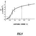
- Fig. 9 is an illustration showing a value of the proportional coefficient Ka with respect to a content of ethylene oxide-2,4,7,9-tetramethyl-5-decyne-4,7-diol (hereinafter referred to as acetylenol: tradename, available from Kawaken Fine Chemical) in the ink, obtained through experiments.
- acetylenol tradename, available from Kawaken Fine Chemical
- Ka value was measured by means of a dynamic penetration testing device S (made by Toyo Seiki Seisakusho).
- a PB paper (tradename) as a plane paper available from Canon Kabushiki Kaisha as applicant of the present invention has been used.
- the PB paper is a printing paper to be used in an electrophotographic type copy machine, a laser beam printer (LBP) and an ink-jet printing type printer.
- a curve shown in Fig. 9 is a curve increasing Ka value (vertical axis) according to increasing of acetylenol content (horizontal axis).
- Ka proportional coefficient
- the proportional coefficient Ka is determined depending upon content of acetylenol. Therefore, penetration speed of the ink is determined substantially depending upon the content of the acetylenol. Lines parallel to the vertical axis and intersecting with the curve represent ranges of fluctuation of the measurement result.
- Figs. 10A and 10B are characteristic charts showing a relationship between the ink penetration amount and the elapsed time, in which are shown results of experiments performed using a printing paper of 64 g/m 2 , of thickness about 80 ⁇ m and of void fraction about 50%.
- the horizontal axis represents (1/2)th power of the elapsed time t (msec 1/2 ), and in Fig. 10B, the horizontal axis represents the elapsed time t (msec).
- the vertical axes represent penetration amount V ( ⁇ m).
- curves of the cases of acetylenol contents of 0%, 0.35% and 1% are shown, respectively.
- Figs. 10A and 10B the penetration amount of the ink relative to the elapsed period becomes greater at greater content of the acetylenol.
- the wet time tw becomes shorter at greater content of acetylenol and ink penetration ability becomes higher at greater content of acetylenol.
- ink penetration ability is low to have a property as low penetrative ink which will be defined later.
- the ink has a property to be penetrated into the printing paper in a short period, and has a property as high penetrative ink.
- the ink in which acetylenol is mixed in the content of 0.35 %, has a property of semi-penetrative ink between the low penetrative ink and the high penetrative ink.
- the foregoing table 1 shows Ka value, acetylenol content (%) and surface tension (dyne/cm) of respective low penetrative ink, the semi-penetrative ink and high penetrative ink, respectively.
- the penetration ability of respective ink for the printing paper as the printing medium becomes higher at greater Ka value. Namely, the penetration ability of the ink becomes higher at smaller surface tension.
- the Ka value has been measured by the dynamic penetration test device S (made by Toyo Seiki Seisakusho) of the liquid by the foregoing Bristow method).
- the PB paper available from Canon Kabushiki Kaisha as applicant of the present invention has been used.
- the PPC paper as a paper for electrophotography available from Canon Kabushiki Kaisha similar result could be obtained.
- CMC critical micell concentration
- the high penetrative ink defined in the foregoing table 1 is appreciated as the ink containing acetylenol at a higher content than that of CMC of acetylenol in water.
- compositions of the treatment liquid and respective inks to be used in this embodiment are as follows:
- pigment dispersion liquid 25 Wt.% food black 2 2 Wt.% glycerin 6 Wt.% trietylene glycol 5 Wt.% acetylenol EH (made by Kawaken Fine Chemical) 0.1 Wt.% water remainder
- the Ka value of this mixed ink of black is 0.33.
- the above pigment dispersion liquid is as follow.
- a pigment dispersion liquid in which self-dispersion type carbon black charged to have anion property and coupled with hydrophilic radical via a phenyl radical on the surface, as expressed by the following chemical formula:
- the pigment ink and the dye ink of black are set as low penetrative ink and the treatment liquid and respective inks of C, M, Y are set as high penetrative ink, respectively.
- the pigment ink not using the dispersant, namely, no dispersant pigment ink, is used.
- anionic carbon black dispersing element self-dispersion type carbon black dispersing element, in which at least one kind of hydrophilic radical is coupled on the surface of the carbon black directly or via other atomic group, is preferred for use.
- self-dispersion type carbon black one having ionicity is preferred, and one charged to have anionic property is preferred.
- the hydrophilic radical to be coupled with the surface of carbon black may be -COOM, -SO 3 M, -PO 3 HM, -PO 3 M 2 , -SO 2 NH 2 , -SO 2 NHCOR and so on (wherein M represents one of hydrogen atom, alkali metal, ammonium and organic ammonium, R represents alkyl radical having carbon atom in a range of 1 to 12, phenyl radical which may have substituent group, or naphthyl radical which may have substituent group), for example.
- M represents one of hydrogen atom, alkali metal, ammonium and organic ammonium
- R represents alkyl radical having carbon atom in a range of 1 to 12, phenyl radical which may have substituent group, or naphthyl radical which may have substituent group
- M in the hydrophilic radical may be alkali metal such as lithium, sodium, potassium or the like.
- the hydrophilic radical may be organic ammonium such as mono-, di-, or tri-methyl ammonium, mono to triethyl ammonium, or mono-, di-, or tri-methanol ammonium.
- a method for obtaining carbon black charged to have anionic property such as for linking -COONa on the surface of carbon black, for example, a method for oxidizing carbon black with hydrochlorite soda can be considered.
- the present invention is not limited to these.
- carbon black on the surface of which hydrophilic radical is coupled with other atom group.
- alkyl group having carbon atom in a range of 1 to 12 phenyl radical which may have substituent group, or naphthyl which may have substituent group may be used.
- -C 2 H 4 COOM, -PhSO 3 M, or -PhCOOM and so on may be used.
- Ph represents phenyl radical
- the present invention is not limited to those exemplified above.
- Carbon black, to the surface of which the anionic radical set forth above is bound directly or via other atom group may be prepared by the following method, for example.
- a method for introducing -COONa radical on the surface of carbon black a method of performing oxidation process for commercially available carbon black with hydrochlorite soda, for example, may be used.
- a method for binding -Ar-COONa radical (wherein Ar represents aryl radical) on the surface of carbon black a method to bind diazonium prepared by acting nitrous acid to NH 2 -Ar-COONa radical on the surface of the carbon black, may be used.
- the present invention should not be limited to these method.
- the self-dispersion type pigment to be contained in the ink of this embodiment is preferred that 80% or more of the particle thereof have particle size within a range of 0.05 to 0.3 ⁇ m, more particularly within a range of 0.1 to 0.25 ⁇ m.
- a method of preparation of such ink is as explained in the foregoing embodiment.
- Carbon black in the no dispersant pigment ink per se does not require addition of pigment dispersion resin or surface-active agent to attain superior water dispersion ability in comparison with the conventional carbon black. Therefore, in comparison with the conventional pigment ink, carbon black set forth above is advantageous in higher fixing ability, higher wetting ability and so on. Thus, such carbon black is superior in reliability as used in the printing head.
- the treatment liquid containing different polarity of high molecular is reacted.
- the ink ejection openings in each printing head are arrayed in a density of 600 dpi.
- the dot density of the image or the like to be printed in the embodiment is 600 dpi in both of row direction and column direction.
- Ejection frequency of respective dot is 4 KHz. Accordingly, a feeding speed of the printing paper becomes about 170 mm/sec.
- a distance D i between the heads 101Bk1 and 101Bk2 of the mixed ink and the treatment liquid of the head 101S is 80 mm.
- a period from ejection of the pigment ink of black to ejection of the treatment liquid becomes about 0.48 sec.
- the ejection amount of each printing head is 15 pl per one ejection. Even when an interval from ejection of the black ink Bk to ejection of the treatment liquid S is set at 0.1 seconds, substantially similar result of evaluation could be obtained.
- both comparative examples show the case where the same predetermined image is printed at resolution of 600 dpi.
- the first comparative example 1 is a system employing only one head ejecting the pigment ink in an amount of 30 pl per one ejection and not using the treatment liquid
- the second comparative example 2 is a system using a head ejecting a dye ink of black in an amount of 30 pl per one ejection and a head ejecting the treatment liquid having relatively low penetration in an amount of 15 pl per one ejection.
- the embodiment and the comparative examples in the foregoing table 2 perform printing of the predetermined image on mutually different 6 kinds of printing papers and the table 2 shows the results of measurement of OD value and so on.
- the OD value is measured using a Machbeth density measuring device.
- a timing, at which water resistance becomes effective, is not a timing where disturbance of image is hardly recognized when water is dripped after printing.
- a fixing ability is a timing where set off is not caused upon discharging of the printed product.
- the system is particularly superior in OD value and fixing ability.
- both of the black inks ejected from the heads 101Bk1 and 101Bk2 for black ink were the pigment inks in the case of the comparative example 3 and the dye inks in the case of the comparative example 4.
- the embodiment exhibits superior OD value. Namely, concerning this OD value, in this embodiment where the treatment liquid is applied for the ink, in which the pigment requiring no dispersant and dye are mixed, the foregoing effect achieved by mixing of the pigment ink and the dye ink to obtain higher OD value than the case where the treatment liquid is applied to only pigment or only dye.
- the full-multi type printing apparatus described above is used in a condition where the printing head is fixed during printing operation. Therefore, a period required for feeding the printing paper substantially correspond a period required for printing.
- the present invention is suitable for high speed printing. Accordingly, by application of the present invention to the high speed printing apparatus, high speed printing function can be further improved. Furthermore, in view of the OD value and restriction of "soaking out”, “overflow” and so on, high quality printing can be achieved.
- the embodiment of the printing apparatus is employed in a printer in the most typical case, the application is not limited to this but can be constructed as a printing portion of copy machine, facsimile and so on.
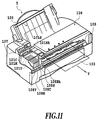
- Fig. 11 is a general perspective view showing a construction of the second embodiment of a serial type printing apparatus 5 according to the present invention.
- the printing apparatus which ejects the treatment liquid after application of the mixed ink on the printing medium for causing reaction, is not limited to the full-line type but can be a serial type apparatus.
- Similar elements to those illustrated in Fig. 7 will be identified by like reference numerals to neglect detailed description thereof in order to avoid redundant disclosure to keep the disclosure simple enough to facilitate clear understanding of the present invention.
- the printing paper 103 as the printing medium is inserted from a paper feeding portion 105 and discharged through a printing portion 126.
- generally widely used inexpensive plain paper is used as the printing paper 103.
- the carriage 107 is constructed to mount the printing heads 101Bk, 101S, 101C, 101M and 101Y and to move reciprocally along the guide rail 109 by a driving force of the not shown motor.
- the printing head 101Bk ejects the mixed ink of black discussed in the former embodiment.
- the printing heads 101S, 101C, 101M and 101Y respectively ejects the treatment liquid, cyan ink, magenta ink and yellow ink and are driven in sequential order for ejecting the treatment liquid and inks.
- the ink and the treatment liquid are supplied from respectively corresponding ink tanks 108Bk, 108S, 108C, 108M and 108Y.
- drive signals are supplied to electrothermal transducers, namely heaters, provided for respective of the ejection openings of respective heads to thereby apply thermal energy to the ink and the treatment liquid for generating bubble.
- a pressure upon bubbling is used to perform ejection of the inks and the treatment liquid.
- 64 ejection openings are arranged at a density of 360 dpi. These 64 ejection openings are arranged in alignment in the same direction as the feeding direction of the printing paper 103, namely in substantially perpendicular direction to scanning direction of each head. In the embodiment, ejection amount per each ejection opening is set at 23 pl.
- a distance between each individual head is 1/2 in. Accordingly, the distance between the heads 101Bk and 101S becomes 1 inch. Since a printing density in the scanning direction is 720 dpi and ejection frequency of each head is 7.2 KHz, a period from ejection of the pigment ink of the head 101 Bk to ejection of the treatment liquid of the head 101S becomes 0.05 sec.
- Figs. 12A to 12C are diagrammatic illustration showing ejection opening arrays of other examples of a head construction in the serial printing apparatus shown in Fig. 11.
- the head may be constructed to have two ejection portions (ejection portions 101Bk1 and 101Bk2) for ejecting black ink as the mixed ink, and the ejection portion 101S ejecting the treatment liquid is arranged therebetween.
- the treatment liquid is applied, and subsequently the mixed ink of black is further applied.
- the head construction shown in Figs. 12B and 12C as well as Fig. 12A is constructed, in which the head constructions for several inks or treatment liquid are integrated.
- the ejection openings per the inks or the treatment liquid or liquid chambers and so forth communicated thereto are mutually separated. Accordingly, each ejection portion is similar to the head of each ink or treatment liquid.
- Fig. 12B shows an example, in which two ejection openings ejecting black ink of the mixed ink.
- the ejection portions 101Bk1 and 101BK2 for the mixed ink and the ejection portion for the treatment liquid are arranged so that the mixed ink is ejected through two ejection portions 101Bk1 and 101Bk2 in advance of ejection of the treatment liquid.
- Fig. 12C shows an example which is similar in arrangement and number to the embodiment shown in Fig. 11 in terms of arrangement and number of ejection portion 101Bk ejecting the mixed ink of the black ink and the ejection portion 101S ejecting the treatment liquid, and is differentiated in constructions of the ejection portions of respective of C, M and Y inks. Respective two ejection portions of respective of C, M, Y inks (ejection portions 101C1, 101C2, ejection openings 101M1, 101M2 and ejection portions 101Y1, 101Y2) are provided.
- the ejection portions 101C1, 101M1 and 101Y1 and ejection portions 101C2, 101M2 and 101Y2 are respectively arranged in the direction perpendicular to the scanning direction, per each ink.
- a plurality of times of scanning with feeding of the printing paper between each scan is effected for overlaying respective inks of C, M and Y.
- Two ejection portions of each ink respectively eject high density and low density inks.
- a ratio of the pigment and the dye may be 3 : 7 in the ejection portion 101Bk1 and 7 : 3 in the ejection portion 101Bk2.
- the ratio may be 7 : 3 in the ejection portion 101Bk1 and 3 : 7 in the ejection portion 101Bk2.
- the printing head or ejection portion are arranged. Namely, in Fig. 12A, the mixed ink of black is ejected from ejection portions 101Bk1 and 101Bk2, and the treatment liquid is ejected from the ejection portion 101S. Then, the mixed ink, the treatment liquid and the mixed ink are ejected in sequential order.
- each ejection portion the ejection openings are arranged at a density of 600 dpi.
- the ejection amount of each ejection opening is 15 pl.
- An interval between the ejection portions is 1/2 inch similarly to the foregoing second embodiment.
- the ejection frequency is 10 KHz, and the resolution in printing is 600 dpi in both of the auxiliary scanning direction (paper feeding direction) and primary scanning direction (head scanning direction). Therefore, interval of ejection of the mixed ink and the treatment liquid becomes 30 msec.
- the treatment liquid contains 0.7% of acetylenol to have high penetrative property.
- the OD value of printing of black character or the like as high as 1.5 or higher can be obtained. Also, fluidizing of the reaction product by the treatment liquid is little, "overflow” or feathering can also be prevented successfully. Since high penetrative type treatment liquid is used, relatively high fixing ability can be achieved.
- the construction of the embodiment illustrated in Figs. 7 and 8 is applied for the mode, in which the pigment ink and the dye ink are ejected individually instead of ejecting the mixed ink.
- the head 101Bk1 for the pigment ink of black respective of the head 101Bk1 for the pigment ink of black, the head 101Bk2 for the dye ink of black, the head 101S for the treatment liquid ejecting the treatment liquid, heads for color inks (cyan head 101C, magenta head 101M and yellow head 101Y) among printing heads of the printing head group 101g are arranged as shown along the feeding direction A of the printing paper 103. Then, by ejecting respective colors of inks and the treatment liquid through respective printing heads, printing of black characters or color image is possible.
- the pigment ink and the dye ink of black to be ejected through the heads 101Bk1 and 101Bk2 respectively are low penetrative inks having low penetration speed
- the treatment liquid and cyan, magenta and yellow inks to be ejected through the heads 101S, 101C, 101M and 101Y, respectively are high penetrative inks having high penetration speed.
- compositions of the inks different from the former embodiment is as follows:
- pigment dispersion liquid 50 Wt.% glycerin 7 Wt.% triethylene glycol 7 Wt.% acetylenol EH (made by Kawaken Fine Chemical) 0.2 Wt.% water remainder
- the pigment ink using no dispersant no dispersant pigment ink
- an anionic carbon black dispersion element self dispersion type carbon black dispersion element, in which at least one kind of hydrophilic radical is coupled on the surface of the carbon black dispersion element via other atom group, is preferred to use.
- the self dispersion type carbon black the carbon black having ionicity, preferably one charged to have anionic property is preferred.
- the treatment liquid having high molecular of different polarity is reacted.
- a distance D i (see Fig. 7) between the head 101Bk1 of the pigment ink and the head 101S of the treatment liquid, is 80 mm. Accordingly, a period from ejection of the pigment ink of black to ejection of the treatment liquid is about 0.48 sec. It should be noted that the ejection amount of the printing head is 15 pl per one ejection.
- the embodiment is particularly superior in the OD value. Namely, concerning this OD value, when the treatment liquid is applied to the mixture of the pigment ink and the dye ink such as this embodiment, the foregoing effect is caused by mixing to achieve higher OD value than the case where the treatment liquid is applied to only pigment ink or only dye ink.
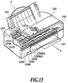
- Fig. 13 is a general perspective view showing the fifth embodiment of the serial type printing apparatus according to the present invention. It is clear that the printer, in which the treatment liquid is reacted after mixing the dye ink and the pigment ink on the printing medium, is applicable not only for the foregoing full-line type, but also for the serial type printing apparatus. Similar elements to those illustrated in Fig. 7 will be identified by like reference numerals to neglect detailed description thereof in order to avoid redundant disclosure to keep the disclosure simple enough to facilitate clear understanding of the present invention.
- the printing paper 103 as the printing medium is inserted from the paper feeding portion 105 and discharged through the printing portion 126.
- generally widely used inexpensive plain paper is used as the printing paper 103.
- the carriage 107 is constructed to mount the printing heads 101Bk1, 101Bk2, 101S, 101C, 101M and 101Y and to move reciprocally along the guide rail 109 by a driving force of the not shown motor.
- the printing head 101Bk1 ejects the pigment ink of black
- the printing head 101Bk2 ejects the dye ink of black.
- the printing heads 101S, 101C, 101M and 101Y respectively eject the treatment liquid, cyan ink, magenta ink and yellow ink, are driven for ejecting the ink and the treatment liquid in the foregoing order.
- the pigment ink of black is no dispersant ink even in the embodiment.
- the inks and the treatment liquid are supplied from the ink tanks 108Bk1, 108Bk2, 108S, 108C, 108M and 108Y.
- drive signals are supplied to electrothermal transducers, namely heaters, provided for respective of the ejection openings of respective heads to thereby apply thermal energy to the ink and the treatment liquid for generating bubble.
- a pressure upon bubbling is used to perform ejection of the inks and the treatment liquid.
- 64 ejection openings are arranged at a density of 360 dpi.
- ejection openings are arranged in alignment in the same direction as the transporting direction Y of the printing paper 103, namely in substantially perpendicular direction to scanning direction of each head.
- ejection amount per each ejection opening is set at 23 pl.
- a distance between each individual head is 1/2 in. Accordingly, the distance between the heads 101Bk and 101S becomes 1 inch. Since a printing density in the scanning direction is 720 dpi and ejection frequency of each head is 7.2 KHz, a period from ejection of the pigment ink of the head 101 Bk to ejection of the treatment liquid of the head 101S becomes 0.1 sec.
- serial type ink-jet printing apparatus shown in Fig. 13 order of arrangement of the printing heads is modified, and associating with this, order of application of the dye ink and pigment ink of black and the treatment liquid is modified.
- arrangement order of the printing heads is modified in order of the head 101Bk1 and head 101Bk2 (other heads are the same as those of the fifth embodiment). Therefore, the pigment ink of black, the treatment liquid, the dye ink of black are ejected on the printing medium in order.
- the distance between the heads and ejection frequency of respective head are similar to the second embodiment.
- fluidization of the reaction product of the ink and the treatment liquid can be restricted in comparison with the case where the treatment liquid is applied after application of the pigment ink and the dye ink. Therefore, occurrence of "overflow” and “sweep" can be successfully suppressed.
- the self dispersion type pigment ink is used for the pigment ink. While the pigment ink of black is ejected from the head 101Bk1 and the dye ink of black is ejected from the head 101Bk2 in the foregoing explanation, it is also possible to eject the dye ink of black from the head 101Bk1, and the pigment ink of black from the head 101Bk2. Even with the later construction, the equivalent effect to that achieved by the former can be achieved. Even when an interval from ejection of the black ink Bk to ejection of the treatment liquid S is set at 0.1 seconds, substantially similar result of evaluation could be obtained.
- a ratio of (self-dispersion type) pigment and dye in the ink and a ratio of cationic high polymer or polyaryl amine (hereinafter referred to as PAA) and cationic surface active agent or Benzelkonium chloride (hereinafter referred to as EBK) in the treatment liquid.
- PAA cationic high polymer or polyaryl amine
- EBK cationic surface active agent or Benzelkonium chloride
- the self-dispersion type pigment is in a form as illustrated in Fig. 15A.
- the pigment is in a burr-like having a large number of fibrous polar group (anionic radical) on the periphery of pigment.
- PAA as cationic high polymer is a corded substance having a plurality of cationic radical in one molecule as shown in Fig. 15D.
- high polymer of PAA may wreathe around the periphery of self-dispersion type pigment as shown in Fig. 16.
- cationic PAA is not possible to be coupled with anionic radical of all pigment geometrically, the coupled substance as a whole is in a condition having cationic property as shown in Fig. 16.
- reaction product generated by fine particle pigment and PAA has small intermolecular force to cause electrical repelling to difficult to aggregate into large block.
- these fine substance may appear as bleeding in smoke form on the periphery of dot.
- reaction mode at a boundary portion between two pigments is preliminary shown. However, reaction mode at another portion is not shown because it is complicated.
- PAA is bound with dye
- bound substance becomes stable in energy.
- EBK is bound with self-dispersion type pigment
- stability in energy is also established. Namely, mode of reaction may have a kind of selectivity.
- the dye when the ratio of PAA is high, in order to improve possibility of causing strike through and edge sharpness, the dye may be increased to restrict flow ability of fine pigment particle.
- the reaction product generated by reaction of PAA and only dye is small in size. Therefore, when penetration ability of the treatment liquid is increased for improving fixing ability, dye may penetrate into the paper in depth direction to make it impossible to obtain high OD value. Therefore, pigment is required. It should be appreciated that presence of the self-dispersion type pigment and dye as coloring material in the ink and presence of high molecular insolubilizing agent in the treatment liquid for making the coloring material in the ink are preferred without presence of pigment basically, even if penetration ability of the treatment liquid is not increased.
Landscapes
- Chemical & Material Sciences (AREA)
- Life Sciences & Earth Sciences (AREA)
- Engineering & Computer Science (AREA)
- Materials Engineering (AREA)
- Wood Science & Technology (AREA)
- Organic Chemistry (AREA)
- Chemical Kinetics & Catalysis (AREA)
- Ink Jet Recording Methods And Recording Media Thereof (AREA)
- Ink Jet (AREA)
- Inks, Pencil-Leads, Or Crayons (AREA)
- Particle Formation And Scattering Control In Inkjet Printers (AREA)
Applications Claiming Priority (6)
| Application Number | Priority Date | Filing Date | Title |
|---|---|---|---|
| JP36145997 | 1997-12-26 | ||
| JP36146097 | 1997-12-26 | ||
| JP36146097 | 1997-12-26 | ||
| JP36145997 | 1997-12-26 | ||
| JP36457098A JP4036407B2 (ja) | 1997-12-26 | 1998-12-22 | インクジェットプリント装置およびその方法 |
| JP36457098 | 1998-12-22 |
Publications (3)
| Publication Number | Publication Date |
|---|---|
| EP0925919A2 true EP0925919A2 (de) | 1999-06-30 |
| EP0925919A3 EP0925919A3 (de) | 2001-09-12 |
| EP0925919B1 EP0925919B1 (de) | 2004-06-16 |
Family
ID=27341648
Family Applications (1)
| Application Number | Title | Priority Date | Filing Date |
|---|---|---|---|
| EP98310743A Expired - Lifetime EP0925919B1 (de) | 1997-12-26 | 1998-12-24 | Tintenstrahldruckapparat |
Country Status (9)
| Country | Link |
|---|---|
| US (2) | US6533409B2 (de) |
| EP (1) | EP0925919B1 (de) |
| JP (1) | JP4036407B2 (de) |
| KR (1) | KR100366907B1 (de) |
| CN (2) | CN1107594C (de) |
| AT (1) | ATE269217T1 (de) |
| AU (1) | AU732271C (de) |
| CA (1) | CA2256954C (de) |
| DE (1) | DE69824536T2 (de) |
Cited By (3)
| Publication number | Priority date | Publication date | Assignee | Title |
|---|---|---|---|---|
| EP1066968A2 (de) * | 1999-07-05 | 2001-01-10 | Canon Kabushiki Kaisha | Tintenstrahldruckvorrichtung und Tintenstrahldruckverfahren |
| EP1167046A1 (de) * | 2000-06-21 | 2002-01-02 | Canon Kabushiki Kaisha | Tintenstrahldruckvorrichtung und Druckverfahren |
| EP1747892A1 (de) * | 2005-07-25 | 2007-01-31 | Brother Kogyo Kabushiki Kaisha | Tintenstrahlaufzeichnungsgerät und Tintenstrahlaufzeichnungsverfahren |
Families Citing this family (27)
| Publication number | Priority date | Publication date | Assignee | Title |
|---|---|---|---|---|
| JP4475620B2 (ja) * | 2000-03-10 | 2010-06-09 | キヤノン株式会社 | インクジェットプリント方法 |
| JP4756780B2 (ja) * | 2000-06-21 | 2011-08-24 | キヤノン株式会社 | インクジェットプリント装置およびインクジェットプリント方法 |
| CN1831056B (zh) * | 2002-09-24 | 2010-06-16 | 精工爱普生株式会社 | 喷墨记录用油墨组合物、使用这种组合物的记录方法和记录物 |
| US7296883B2 (en) * | 2002-09-24 | 2007-11-20 | Seiko Epson Corporation | Ink composition for ink-jet recording, recording method using same, and record |
| JP4508703B2 (ja) * | 2003-04-24 | 2010-07-21 | キヤノン株式会社 | インクジェット用インク及びこれを用いたインクジェット記録方法 |
| JP4164418B2 (ja) * | 2003-07-17 | 2008-10-15 | キヤノン株式会社 | 記録装置、記録方法、およびプログラム |
| WO2005044574A1 (en) * | 2003-11-07 | 2005-05-19 | Ricoh Company, Ltd. | Ink set, treating liquid, recording liquid, image recording apparatus and image recording method |
| JP2006021390A (ja) * | 2004-07-07 | 2006-01-26 | Canon Inc | インクジェット記録装置 |
| JP4603844B2 (ja) * | 2004-10-05 | 2010-12-22 | キヤノン株式会社 | パターン形成装置およびパターン形成方法 |
| US7951233B2 (en) * | 2004-10-25 | 2011-05-31 | Hewlett-Packard Development Company, L.P. | Reactive color inks |
| US7478902B2 (en) * | 2004-11-04 | 2009-01-20 | Hewlett-Packard Development Company, L.P. | Inkjet compositions |
| US7654662B2 (en) * | 2004-11-19 | 2010-02-02 | Canon Kabushiki Kaisha | Ink jet printing method and ink jet printing apparatus |
| JP4812078B2 (ja) | 2004-12-28 | 2011-11-09 | キヤノン株式会社 | インクジェット記録装置 |
| JP2006212787A (ja) | 2005-02-01 | 2006-08-17 | Canon Inc | インクジェット記録装置 |
| JP4872310B2 (ja) * | 2005-10-31 | 2012-02-08 | セイコーエプソン株式会社 | ブラックインク組成物少なくとも3種を含むインクセット |
| EP1992495B1 (de) * | 2006-03-09 | 2012-10-31 | Canon Kabushiki Kaisha | Tintenstrahlaufzeichnungsverfahren |
| JP2008162124A (ja) * | 2006-12-28 | 2008-07-17 | Brother Ind Ltd | 印刷システム、印刷制御装置、印刷制御用プログラム及びその記録媒体 |
| JP4977637B2 (ja) * | 2008-02-06 | 2012-07-18 | 理想科学工業株式会社 | インクジェット印刷方法及びインクセット |
| JP5381530B2 (ja) * | 2009-09-10 | 2014-01-08 | セイコーエプソン株式会社 | 印刷装置、及び、印刷装置の制御方法 |
| JP5655353B2 (ja) * | 2010-04-01 | 2015-01-21 | セイコーエプソン株式会社 | 印刷制御装置及び印刷制御プログラム |
| JP5539122B2 (ja) * | 2010-08-31 | 2014-07-02 | キヤノン株式会社 | 画像処理方法および画像処理装置 |
| CN103958539B (zh) * | 2011-09-13 | 2019-12-17 | 孟山都技术公司 | 用于杂草控制的方法和组合物 |
| US9463642B1 (en) * | 2015-07-29 | 2016-10-11 | Eastman Kodak Company | Image authentication using material penetration characteristics |
| EP3403841B1 (de) * | 2017-05-17 | 2020-09-23 | Canon Kabushiki Kaisha | Tintenstrahldruckverfahren und tintenstrahldruckvorrichtung |
| JP7056159B2 (ja) * | 2018-01-16 | 2022-04-19 | セイコーエプソン株式会社 | 印刷装置および印刷方法 |
| US10647144B2 (en) | 2018-02-23 | 2020-05-12 | Canon Kabushiki Kaisha | Ink jet recording method |
| CN113447495A (zh) * | 2021-06-29 | 2021-09-28 | 国网黑龙江省电力有限公司电力科学研究院 | 一种高温金属表面探伤方法 |
Family Cites Families (59)
| Publication number | Priority date | Publication date | Assignee | Title |
|---|---|---|---|---|
| US8A (en) * | 1836-08-10 | T Blanchard | Machine for cutting scores around ships' tackle blocks and dead eyes | |
| US587164A (en) * | 1897-07-27 | Dynamo-electric machine | ||
| US650840A (en) * | 1899-11-15 | 1900-06-05 | Eddy Electric Mfg Company | Steering mechanism for motor-vehicles. |
| US678396A (en) * | 1900-09-29 | 1901-07-16 | Robert A Nelles | Rotary plow. |
| US703087A (en) * | 1902-03-13 | 1902-06-24 | Henry H Schenk | Tank-heater. |
| US724968A (en) * | 1902-09-11 | 1903-04-07 | Clinton Roads E | Fire-extinguishing apparatus. |
| US726150A (en) * | 1902-10-01 | 1903-04-21 | Frances M Dwight | Balancing device for cultivators or the like. |
| US726155A (en) * | 1902-12-09 | 1903-04-21 | Chaplin Fulton Mfg Company | Steam-trap. |
| US791470A (en) * | 1903-03-09 | 1905-06-06 | Eugene D Jefferson | Vomiting-keir. |
| US788885A (en) * | 1904-04-08 | 1905-05-02 | William L Church | Dam. |
| US802246A (en) * | 1905-03-17 | 1905-10-17 | Bryant Electric Co | Electrical fuse-plug. |
| JPS58128862A (ja) * | 1982-01-26 | 1983-08-01 | Minolta Camera Co Ltd | インクジエツト記録方法 |
| DE3332491C2 (de) * | 1983-09-08 | 1985-10-10 | Siemens AG, 1000 Berlin und 8000 München | Vorrichtung für Tintenschreibeinrichtungen zum Beschreiben eines Aufzeichnungsträgers |
| JP2668442B2 (ja) * | 1989-08-04 | 1997-10-27 | キヤノン株式会社 | 記録媒体及びインクジェット記録方法 |
| JP2627200B2 (ja) * | 1989-11-20 | 1997-07-02 | 富士写真フイルム株式会社 | 自己分散型着色体、静電写真用液体現像剤、補給トナーおよびトナーキツト |
| JP3064318B2 (ja) * | 1990-02-20 | 2000-07-12 | セイコーエプソン株式会社 | 印写方法 |
| JPH03240558A (ja) * | 1990-02-20 | 1991-10-25 | Seiko Epson Corp | 印写方法 |
| US5169436A (en) * | 1992-05-13 | 1992-12-08 | E. I. Du Pont De Nemours And Company | Sulfur-containing penetrants for ink jet inks |
| JPH0615948A (ja) * | 1992-07-02 | 1994-01-25 | Fuji Xerox Co Ltd | インクジェット用記録紙及びその記録紙を用いたインクジェット記録方法 |
| ATE176202T1 (de) * | 1992-07-24 | 1999-02-15 | Canon Kk | Tintenstrahlaufzeichnungsverfahren unter verwendung von tinten mit verschiedenen merkmalen und vorrichtung dafür |
| EP0587164B1 (de) * | 1992-09-10 | 1998-12-23 | Canon Kabushiki Kaisha | Verfahren und Vorrichtung für Tintenstrahlaufzeichnung |
| JP3210095B2 (ja) * | 1992-10-13 | 2001-09-17 | ハッコールケミカル株式会社 | 有機白色顔料 |
| JPH0796603A (ja) * | 1993-07-31 | 1995-04-11 | Sony Corp | インクジェット記録装置 |
| JPH0747762A (ja) * | 1993-08-09 | 1995-02-21 | Fuji Xerox Co Ltd | インクジェット記録方法及びその装置 |
| DE69422571T2 (de) * | 1993-10-08 | 2000-06-15 | Toshiba Kawasaki Kk | Pigmentdispersion, Anzeigevorrichtung und Verfahren zur Herstellung dieser Vorrichtung |
| US5992971A (en) * | 1993-10-28 | 1999-11-30 | Canon Kabushiki Kaisha | Ink jet recording method and apparatus |
| ATE183143T1 (de) * | 1994-03-08 | 1999-08-15 | Canon Kk | Aufzeichnungspapier, tintenstrahlaufzeichnungsverfahren und aufzeichnungssystem unter verwendung des aufzeichnungspapiers |
| JP3227339B2 (ja) * | 1994-05-23 | 2001-11-12 | キヤノン株式会社 | インクジェット記録装置及びインクジェット記録方法ならびに記録物 |
| US6412934B1 (en) | 1994-08-10 | 2002-07-02 | Canon Kabushiki Kaisha | Ink jet printing method and apparatus |
| JP3347541B2 (ja) * | 1994-08-10 | 2002-11-20 | キヤノン株式会社 | インクジェット記録方法、インクジェット記録装置、記録ヘッド、情報処理システム、および記録物 |
| JP3288867B2 (ja) * | 1994-09-02 | 2002-06-04 | キヤノン株式会社 | インクジェット記録装置 |
| US6350022B1 (en) * | 1994-09-02 | 2002-02-26 | Canon Kabushiki Kaisha | Ink jet recording apparatus |
| AUPM845694A0 (en) * | 1994-09-28 | 1994-10-20 | University Of Sydney, The | Identification of homologous genes across species boundaries |
| US5574530A (en) | 1994-10-19 | 1996-11-12 | Fuji Photo Film Co., Ltd. | Device for applying solvent for forming an image |
| US5571311A (en) * | 1994-12-15 | 1996-11-05 | Cabot Corporation | Ink jet ink formulations containing carbon black products |
| US5835116A (en) * | 1995-01-31 | 1998-11-10 | Canon Kabushiki Kaisha | Image forming method employing ink-jet recording system |
| JP3559637B2 (ja) | 1995-01-31 | 2004-09-02 | キヤノン株式会社 | 画像形成方法、インクセット、インク、インクの調製方法及びカラー画像の異色境界滲みの低減方法 |
| JP3337879B2 (ja) * | 1995-02-13 | 2002-10-28 | キヤノン株式会社 | インクジェットプリント方法およびこれに用いられるインクジェットヘッド、インクジェットカートリッジおよびインクジェットプリント装置 |
| US6102537A (en) * | 1995-02-13 | 2000-08-15 | Canon Kabushiki Kaisha | Method and apparatus for ink-jet printing |
| US5953026A (en) * | 1995-02-13 | 1999-09-14 | Canon Kabushiki Kaisha | Ink jet printing apparatus, method of disposing waste liquids and apparatus therefor |
| JP3190535B2 (ja) * | 1995-02-13 | 2001-07-23 | キヤノン株式会社 | インクジェットプリント装置およびインクジェットプリント方法 |
| JP3320289B2 (ja) | 1995-02-13 | 2002-09-03 | キヤノン株式会社 | インクジェットヘッド、インクジェットカートリッジおよびプリント装置ならびにインクジェットプリント方法 |
| JP3313963B2 (ja) * | 1995-02-13 | 2002-08-12 | キヤノン株式会社 | インクジェットプリント方法およびプリント装置 |
| JP3320292B2 (ja) * | 1995-02-13 | 2002-09-03 | キヤノン株式会社 | インクジェットプリント装置およびインクジェットプリント方法 |
| US6024439A (en) * | 1995-09-21 | 2000-02-15 | Canon Kabushiki Kaisha | Ink-jet head having projecting portion |
| EP0767225B1 (de) * | 1995-10-06 | 2003-04-23 | Seiko Epson Corporation | Tintenzusammensetzung für das Tintenstrahlaufzeichnen und Tintenstrahl-Aufzeichnungsverfahren |
| EP0802246B1 (de) * | 1995-11-02 | 2004-03-31 | Seiko Epson Corporation | Set farbige tinte zur tintenstrahlaufzeichnung |
| JPH09272203A (ja) * | 1996-02-09 | 1997-10-21 | Canon Inc | インクジェット記録装置および記録方法 |
| US6113290A (en) * | 1996-02-21 | 2000-09-05 | Canon Kabushiki Kaisha | Ink jet recording apparatus having improved edge detecting and edge formation |
| US6074052A (en) * | 1996-04-19 | 2000-06-13 | Canon Kabushiki Kaisha | Ink jet printing method and ink jet recording apparatus |
| US6027210A (en) * | 1996-08-02 | 2000-02-22 | Canon Kabushiki Kaisha | Ink-jet recording process using liquid formulation and ink in combination |
| JP3313977B2 (ja) * | 1996-08-02 | 2002-08-12 | キヤノン株式会社 | インクジェット記録方法およびインクジェット記録装置 |
| JP3320317B2 (ja) * | 1996-09-03 | 2002-09-03 | キヤノン株式会社 | インクジェットプリント装置およびプリント方法 |
| US6164754A (en) * | 1996-11-06 | 2000-12-26 | Canon Kabushiki Kaisha | Liquid discharging recording apparatus with elastic head cleaning member |
| JP3209930B2 (ja) * | 1996-11-22 | 2001-09-17 | キヤノン株式会社 | インクジェットプリント装置、インクジェットプリント方法およびデータ作成方法 |
| JP3673617B2 (ja) * | 1997-06-26 | 2005-07-20 | キヤノン株式会社 | インクジェット記録装置およびインクジェット記録方法 |
| US6471757B1 (en) * | 1997-10-30 | 2002-10-29 | Canon Kabushiki Kaisha | Ink, ink container, ink set, ink jet printing apparatus, and ink jet printing method |
| US6379000B1 (en) | 1997-12-26 | 2002-04-30 | Canon Kabushiki Kaisha | Method of forming image and apparatus of the same |
| US6582047B2 (en) * | 2000-11-17 | 2003-06-24 | Canon Kabushiki Kaisha | Ink jet printing apparatus and ink jet printing method |
-
1998
- 1998-12-22 JP JP36457098A patent/JP4036407B2/ja not_active Expired - Fee Related
- 1998-12-23 CA CA002256954A patent/CA2256954C/en not_active Expired - Fee Related
- 1998-12-24 US US09/219,895 patent/US6533409B2/en not_active Expired - Fee Related
- 1998-12-24 AU AU98185/98A patent/AU732271C/en not_active Ceased
- 1998-12-24 DE DE69824536T patent/DE69824536T2/de not_active Expired - Lifetime
- 1998-12-24 EP EP98310743A patent/EP0925919B1/de not_active Expired - Lifetime
- 1998-12-24 AT AT98310743T patent/ATE269217T1/de not_active IP Right Cessation
- 1998-12-25 CN CN98111650A patent/CN1107594C/zh not_active Expired - Fee Related
- 1998-12-25 CN CNB021220824A patent/CN1193891C/zh not_active Expired - Fee Related
- 1998-12-26 KR KR10-1998-0058929A patent/KR100366907B1/ko not_active IP Right Cessation
-
2003
- 2003-01-13 US US10/340,762 patent/US6786587B2/en not_active Expired - Lifetime
Cited By (7)
| Publication number | Priority date | Publication date | Assignee | Title |
|---|---|---|---|---|
| EP1066968A2 (de) * | 1999-07-05 | 2001-01-10 | Canon Kabushiki Kaisha | Tintenstrahldruckvorrichtung und Tintenstrahldruckverfahren |
| EP1066968A3 (de) * | 1999-07-05 | 2001-10-10 | Canon Kabushiki Kaisha | Tintenstrahldruckvorrichtung und Tintenstrahldruckverfahren |
| US6517191B1 (en) | 1999-07-05 | 2003-02-11 | Canon Kabushiki Kaisha | Ink jet printing apparatus and ink jet printing method |
| EP1167046A1 (de) * | 2000-06-21 | 2002-01-02 | Canon Kabushiki Kaisha | Tintenstrahldruckvorrichtung und Druckverfahren |
| US6557991B2 (en) | 2000-06-21 | 2003-05-06 | Canon Kabushiki Kaisha | Ink jet recording apparatus and printing method thereof |
| EP1747892A1 (de) * | 2005-07-25 | 2007-01-31 | Brother Kogyo Kabushiki Kaisha | Tintenstrahlaufzeichnungsgerät und Tintenstrahlaufzeichnungsverfahren |
| US7604310B2 (en) | 2005-07-25 | 2009-10-20 | Brother Kogyo Kabushiki Kaisha | Inkjet recording apparatus and inkjet recording method |
Also Published As
| Publication number | Publication date |
|---|---|
| US20030122912A1 (en) | 2003-07-03 |
| CN1193891C (zh) | 2005-03-23 |
| KR19990063500A (ko) | 1999-07-26 |
| ATE269217T1 (de) | 2004-07-15 |
| CA2256954C (en) | 2003-07-29 |
| EP0925919B1 (de) | 2004-06-16 |
| CA2256954A1 (en) | 1999-06-26 |
| EP0925919A3 (de) | 2001-09-12 |
| JP4036407B2 (ja) | 2008-01-23 |
| US6786587B2 (en) | 2004-09-07 |
| AU732271B2 (en) | 2001-04-12 |
| DE69824536D1 (de) | 2004-07-22 |
| CN1223934A (zh) | 1999-07-28 |
| JPH11245394A (ja) | 1999-09-14 |
| AU9818598A (en) | 1999-07-15 |
| DE69824536T2 (de) | 2005-06-30 |
| KR100366907B1 (ko) | 2003-05-12 |
| AU732271C (en) | 2003-10-30 |
| US6533409B2 (en) | 2003-03-18 |
| US20020036687A1 (en) | 2002-03-28 |
| CN1107594C (zh) | 2003-05-07 |
| CN1389351A (zh) | 2003-01-08 |
Similar Documents
| Publication | Publication Date | Title |
|---|---|---|
| CA2256954C (en) | Ink-jet printing apparatus | |
| KR100338617B1 (ko) | 잉크의 색재를 불용화시키는 기능을 가진 잉크를 사용하여 프린트하는 잉크 프린트 방법 및 잉크젯 프린트 장치 | |
| US6550904B2 (en) | Ink printing method and ink printer | |
| EP2116381B1 (de) | Tintenstrahldruckapparat | |
| US6474778B1 (en) | Ink jet printing apparatus and ink jet printing method | |
| JP3997019B2 (ja) | プリント方法およびプリント装置 | |
| EP0926212B1 (de) | Bildherstellungverfahren und Vorrichtung zur Bildherstellung | |
| US6367923B1 (en) | Ink-jet printing method, system using an ink and a treating liquid, and ink set | |
| JP3762125B2 (ja) | インクプリント方法およびインクプリント装置 | |
| EP1066968B1 (de) | Tintenstrahldruckvorrichtung und Tintenstrahldruckverfahren | |
| JP4343329B2 (ja) | インクプリント方法およびインクジェットプリント装置 | |
| JP4036463B2 (ja) | インクジェットプリント装置およびプリント方法 |
Legal Events
| Date | Code | Title | Description |
|---|---|---|---|
| PUAI | Public reference made under article 153(3) epc to a published international application that has entered the european phase |
Free format text: ORIGINAL CODE: 0009012 |
|
| AK | Designated contracting states |
Kind code of ref document: A2 Designated state(s): AT BE CH CY DE DK ES FI FR GB GR IE IT LI LU MC NL PT SE Kind code of ref document: A2 Designated state(s): AT BE CH DE DK ES FI FR GB GR IE IT LI LU MC NL PT SE |
|
| AX | Request for extension of the european patent |
Free format text: AL;LT;LV;MK;RO;SI |
|
| PUAL | Search report despatched |
Free format text: ORIGINAL CODE: 0009013 |
|
| AK | Designated contracting states |
Kind code of ref document: A3 Designated state(s): AT BE CH CY DE DK ES FI FR GB GR IE IT LI LU MC NL PT SE |
|
| AX | Request for extension of the european patent |
Free format text: AL;LT;LV;MK;RO;SI |
|
| 17P | Request for examination filed |
Effective date: 20020128 |
|
| AKX | Designation fees paid |
Free format text: AT BE CH DE DK ES FI FR GB GR IE IT LI LU MC NL PT SE |
|
| 17Q | First examination report despatched |
Effective date: 20020813 |
|
| GRAP | Despatch of communication of intention to grant a patent |
Free format text: ORIGINAL CODE: EPIDOSNIGR1 |
|
| GRAS | Grant fee paid |
Free format text: ORIGINAL CODE: EPIDOSNIGR3 |
|
| GRAA | (expected) grant |
Free format text: ORIGINAL CODE: 0009210 |
|
| AK | Designated contracting states |
Kind code of ref document: B1 Designated state(s): AT BE CH DE DK ES FI FR GB GR IE IT LI LU MC NL PT SE |
|
| PG25 | Lapsed in a contracting state [announced via postgrant information from national office to epo] |
Ref country code: NL Free format text: LAPSE BECAUSE OF FAILURE TO SUBMIT A TRANSLATION OF THE DESCRIPTION OR TO PAY THE FEE WITHIN THE PRESCRIBED TIME-LIMIT Effective date: 20040616 Ref country code: LI Free format text: LAPSE BECAUSE OF FAILURE TO SUBMIT A TRANSLATION OF THE DESCRIPTION OR TO PAY THE FEE WITHIN THE PRESCRIBED TIME-LIMIT Effective date: 20040616 Ref country code: FI Free format text: LAPSE BECAUSE OF FAILURE TO SUBMIT A TRANSLATION OF THE DESCRIPTION OR TO PAY THE FEE WITHIN THE PRESCRIBED TIME-LIMIT Effective date: 20040616 Ref country code: CH Free format text: LAPSE BECAUSE OF FAILURE TO SUBMIT A TRANSLATION OF THE DESCRIPTION OR TO PAY THE FEE WITHIN THE PRESCRIBED TIME-LIMIT Effective date: 20040616 Ref country code: BE Free format text: LAPSE BECAUSE OF FAILURE TO SUBMIT A TRANSLATION OF THE DESCRIPTION OR TO PAY THE FEE WITHIN THE PRESCRIBED TIME-LIMIT Effective date: 20040616 Ref country code: AT Free format text: LAPSE BECAUSE OF FAILURE TO SUBMIT A TRANSLATION OF THE DESCRIPTION OR TO PAY THE FEE WITHIN THE PRESCRIBED TIME-LIMIT Effective date: 20040616 |
|
| REG | Reference to a national code |
Ref country code: GB Ref legal event code: FG4D |
|
| REG | Reference to a national code |
Ref country code: CH Ref legal event code: EP |
|
| REF | Corresponds to: |
Ref document number: 69824536 Country of ref document: DE Date of ref document: 20040722 Kind code of ref document: P |
|
| REG | Reference to a national code |
Ref country code: IE Ref legal event code: FG4D |
|
| PG25 | Lapsed in a contracting state [announced via postgrant information from national office to epo] |
Ref country code: SE Free format text: LAPSE BECAUSE OF FAILURE TO SUBMIT A TRANSLATION OF THE DESCRIPTION OR TO PAY THE FEE WITHIN THE PRESCRIBED TIME-LIMIT Effective date: 20040916 Ref country code: GR Free format text: LAPSE BECAUSE OF FAILURE TO SUBMIT A TRANSLATION OF THE DESCRIPTION OR TO PAY THE FEE WITHIN THE PRESCRIBED TIME-LIMIT Effective date: 20040916 Ref country code: DK Free format text: LAPSE BECAUSE OF FAILURE TO SUBMIT A TRANSLATION OF THE DESCRIPTION OR TO PAY THE FEE WITHIN THE PRESCRIBED TIME-LIMIT Effective date: 20040916 |
|
| PG25 | Lapsed in a contracting state [announced via postgrant information from national office to epo] |
Ref country code: ES Free format text: LAPSE BECAUSE OF FAILURE TO SUBMIT A TRANSLATION OF THE DESCRIPTION OR TO PAY THE FEE WITHIN THE PRESCRIBED TIME-LIMIT Effective date: 20040927 |
|
| NLV1 | Nl: lapsed or annulled due to failure to fulfill the requirements of art. 29p and 29m of the patents act | ||
| PG25 | Lapsed in a contracting state [announced via postgrant information from national office to epo] |
Ref country code: LU Free format text: LAPSE BECAUSE OF NON-PAYMENT OF DUE FEES Effective date: 20041224 Ref country code: IE Free format text: LAPSE BECAUSE OF NON-PAYMENT OF DUE FEES Effective date: 20041224 |
|
| PG25 | Lapsed in a contracting state [announced via postgrant information from national office to epo] |
Ref country code: MC Free format text: LAPSE BECAUSE OF NON-PAYMENT OF DUE FEES Effective date: 20041231 |
|
| REG | Reference to a national code |
Ref country code: CH Ref legal event code: PL |
|
| ET | Fr: translation filed | ||
| PLBE | No opposition filed within time limit |
Free format text: ORIGINAL CODE: 0009261 |
|
| STAA | Information on the status of an ep patent application or granted ep patent |
Free format text: STATUS: NO OPPOSITION FILED WITHIN TIME LIMIT |
|
| 26N | No opposition filed |
Effective date: 20050317 |
|
| REG | Reference to a national code |
Ref country code: IE Ref legal event code: MM4A |
|
| PGFP | Annual fee paid to national office [announced via postgrant information from national office to epo] |
Ref country code: IT Payment date: 20061231 Year of fee payment: 9 |
|
| PG25 | Lapsed in a contracting state [announced via postgrant information from national office to epo] |
Ref country code: PT Free format text: LAPSE BECAUSE OF NON-PAYMENT OF DUE FEES Effective date: 20041116 |
|
| PGFP | Annual fee paid to national office [announced via postgrant information from national office to epo] |
Ref country code: FR Payment date: 20061218 Year of fee payment: 9 |
|
| REG | Reference to a national code |
Ref country code: FR Ref legal event code: ST Effective date: 20081020 |
|
| PG25 | Lapsed in a contracting state [announced via postgrant information from national office to epo] |
Ref country code: FR Free format text: LAPSE BECAUSE OF NON-PAYMENT OF DUE FEES Effective date: 20071231 |
|
| PG25 | Lapsed in a contracting state [announced via postgrant information from national office to epo] |
Ref country code: IT Free format text: LAPSE BECAUSE OF NON-PAYMENT OF DUE FEES Effective date: 20071224 |
|
| PGFP | Annual fee paid to national office [announced via postgrant information from national office to epo] |
Ref country code: GB Payment date: 20131217 Year of fee payment: 16 Ref country code: DE Payment date: 20131231 Year of fee payment: 16 |
|
| REG | Reference to a national code |
Ref country code: DE Ref legal event code: R119 Ref document number: 69824536 Country of ref document: DE |
|
| GBPC | Gb: european patent ceased through non-payment of renewal fee |
Effective date: 20141224 |
|
| PG25 | Lapsed in a contracting state [announced via postgrant information from national office to epo] |
Ref country code: GB Free format text: LAPSE BECAUSE OF NON-PAYMENT OF DUE FEES Effective date: 20141224 Ref country code: DE Free format text: LAPSE BECAUSE OF NON-PAYMENT OF DUE FEES Effective date: 20150701 |