EP0919653A2 - WEbmaschine, insbesondere Luftdüsenwebmaschine - Google Patents
WEbmaschine, insbesondere Luftdüsenwebmaschine Download PDFInfo
- Publication number
- EP0919653A2 EP0919653A2 EP98120770A EP98120770A EP0919653A2 EP 0919653 A2 EP0919653 A2 EP 0919653A2 EP 98120770 A EP98120770 A EP 98120770A EP 98120770 A EP98120770 A EP 98120770A EP 0919653 A2 EP0919653 A2 EP 0919653A2
- Authority
- EP
- European Patent Office
- Prior art keywords
- main
- nozzle
- nozzles
- longitudinal center
- nozzle block
- Prior art date
- Legal status (The legal status is an assumption and is not a legal conclusion. Google has not performed a legal analysis and makes no representation as to the accuracy of the status listed.)
- Granted
Links
Images
Classifications
-
- D—TEXTILES; PAPER
- D03—WEAVING
- D03D—WOVEN FABRICS; METHODS OF WEAVING; LOOMS
- D03D47/00—Looms in which bulk supply of weft does not pass through shed, e.g. shuttleless looms, gripper shuttle looms, dummy shuttle looms
- D03D47/28—Looms in which bulk supply of weft does not pass through shed, e.g. shuttleless looms, gripper shuttle looms, dummy shuttle looms wherein the weft itself is projected into the shed
- D03D47/30—Looms in which bulk supply of weft does not pass through shed, e.g. shuttleless looms, gripper shuttle looms, dummy shuttle looms wherein the weft itself is projected into the shed by gas jet
- D03D47/3006—Construction of the nozzles
- D03D47/3013—Main nozzles
Definitions
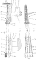
- the invention relates to a loom, in particular an air jet loom a leaf bar carrying a reed, which is used for the purpose of entry and posting of weft threads on the stop edge of a fabric from an entry position into a Stop position and in the opposite direction about a longitudinal axis of a drive or blade shaft executes uniform oscillating movements with a first nozzle arrangement, which consists of several main nozzles with blowpipe, the main nozzles after one Order system are included in a main nozzle block and where the Main nozzle block is connected to the blade strip which carries out the oscillating movements, and with a second, upstream of the first nozzle arrangement, stationary nozzle arrangement, which consists of several pre-nozzles with blowpipe, the Thread guide channel of each blowpipe of the respective pre-nozzle at the time of Weft thread entry aligned with the thread guide channel of the blowpipe of the respective Main nozzle is opposite.
- Known air jet looms have one for weft insertion Main nozzle block with several in it according to a certain order system recorded, pneumatically actuated main nozzles with a blow pipe of a certain length, wherein the respective blow pipe is directed to the weft insertion channel of a reed.
- the main nozzle block is on the weaving machine's leaf bar carrying the reed arranged and in such a way that the main nozzle block is adjustable relative to the reed.
- the respective pre-nozzle has a blow pipe of a certain length, which in the direction of respective main nozzle is aligned that the weft damaging Weft deflections are largely avoided.
- the object is achieved in that the individual pre-nozzles with a blowpipe according to a classification system of the main nozzles in the main nozzle block Order system are included in a pre-nozzle block, which order system enables that by aligning a single pre-nozzle to the main nozzle in question all other pre-nozzles are aligned with the relevant main nozzles during the weft insertion even if the pre-nozzle block is on one of the blade strips independent, stationary carrier is mounted.
- the pre-nozzle block can be arranged on a carrier connected to the weaving machine so that it can be rotated about its longitudinal center axis in a corresponding arrangement system.
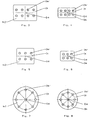
- a specific order of the pre and main nozzles is given, for example, if the center axes of the nozzles are arranged symmetrically about the longitudinal center axis of the nozzle blocks on a circular path. In such a case it is achieved that by rotating the pre-nozzle block about its longitudinal center axis, each pre-nozzle can be assigned to any main nozzle.
- Such a procedure can be of importance if weft threads of different quality are processed into a fabric and, for example, a weft thread requires a pre-nozzle which is designed differently from the main nozzle.
- the relevant front nozzle can then be assigned to the relevant main nozzle within a short period of time. It is therefore essential to the invention that with the alignment of a single pre-nozzle on the main nozzle in question, all other pre-nozzles are inevitably aligned with their associated main nozzles.
- the weaving reed 1 which is only partially shown, is mounted on the so-called leaf bar 2, a weaving machine 11, which is not shown here.
- a main nozzle arrangement 5 is shown detachably connected to the blade strip 2 in front of the reed 1.
- the blade bar 2 periodically swings together with the reed 1 for the purpose of attaching weft threads 3 to the stop edge of a fabric (not shown here) about the longitudinal axis 4a of a drive or blade shaft 4.
- the main nozzle arrangement 5 consequently also swings about the axis 4a in the movement rhythm of the blade strip 2.
- the main nozzle arrangement 5 forms a main nozzle block 6.
- the main nozzles 5a are arranged in the main nozzle block 6 according to a certain system. Such a particular system is shown in Figures 4, 6 and 8.
- the main nozzles 5a are equipped with a blow pipe 5b.
- a thread guide channel 5b runs through the main nozzles 5a and the associated blow pipe 5b over their length.
- the main nozzle block 6 and the free ends of the blowpipes 5b are carried by a cooler 13, which establishes the connection to the sheet bar 2.
- the connecting means 14 are shown symbolically.
- a pre-nozzle arrangement 8 is positioned in front of the main nozzle arrangement 5 in the weft direction 7.
- the pre-nozzle arrangement 8 is stationary connected to a machine-fixed support 12.
- a holder 15 accommodates a pre-nozzle block 9, in which pre-nozzles 8a with a blowpipe 8b are integrated according to the invention, namely according to an order system which corresponds to that of the main nozzles 5a in the main nozzle block 6.
- the cooler 15 is connected to the carrier 12 via symbolically represented connection means 16.
- the arrangement system of the pre-nozzles 8a in the pre-nozzle block 9 is shown in FIGS. 3, 5 and 7.
- the sheet bar 2 with the superstructures 1, 5 and 13 is in the insertion position of the weft thread 3.
- the pre-nozzle arrangement 8 is permanently in this position, as a result of which the thread guide channels 5b 'and 8b' then lie flush with one another.
- Such an arrangement has the advantage, inter alia, that deflections of the weft threads at the outlet of the blowpipes 8b and at the inlet of the main nozzles 5a are excluded at the time of the weft thread insertion and that, as already mentioned above, due to an identical ordering system between the main and pre-nozzles and the combination of all pre-nozzles in one pre-nozzle block, the effort for aligning the pre-nozzles on the main nozzles is minimized.
Landscapes
- Engineering & Computer Science (AREA)
- Textile Engineering (AREA)
- Looms (AREA)
- Jet Pumps And Other Pumps (AREA)
- Air-Conditioning For Vehicles (AREA)
- Food Preservation Except Freezing, Refrigeration, And Drying (AREA)
- Solid-Sorbent Or Filter-Aiding Compositions (AREA)
- Polysaccharides And Polysaccharide Derivatives (AREA)
- Buffer Packaging (AREA)
- Management, Administration, Business Operations System, And Electronic Commerce (AREA)
- Prostheses (AREA)
Abstract
Description
Ein bestimmtes Ordnungssystem der Vor- und Hauptdüsen ist z.B. dann gegeben, wenn die Mittenachsen der Düsen symmetrisch um die Längsmittenachse der Düsenblöcke auf einer Kreisbahn angeordnet sind.
In einem solchen Fall wird erreicht, daß durch Drehen des Vordüsenblockes um seine Längsmittenachse jede Vordüse einer beliebigen Hauptdüse zugeordnet werden kann.
Ein solches Vorgehen kann dann von Bedeutung sein, wenn Schußfäden verschiedener Qualität zu einem Gewebe verarbeitet werden und z.B. ein Schußfaden eine von der Hauptdüse abweichend konstruktiv ausgebildete Vordüse erfordert.
Innerhalb einer kurzen Zeitdauer ist dann die betreffende Vordüse der betreffenden Hauptdüse zuordenbar.
Erfindungswesentlich ist also, daß mit dem Ausrichten einer einzigen Vordüse auf die betreffende Hauptdüse alle übrigen Vordüsen auf ihre zugeordneten Hauptdüsen zwangsläufig fluchtend ausgerichtet sind.
- Figur 1
- die Vorderansicht des Haupt- und Vordüsenblockes mit Haupt- und Vordüsen in getrennter Anordnung,
- Figur 2
- die Draufsicht des Haupt- und Vordüsenblockes mit Haupt- und Vordüsen,
- Figur 3
- ein Ordnungssystem der Vordüsen im Vordüsenblock nach Ansicht A gem. Figur 2,
- Figur 4
- ein Ordnungssystem der Hauptdüsen im Hauptdüsenblock nach Ansicht B gem. Figur 2,
- Figur 5
- ein Ordnungssystem der Vordüsen im Vordüsenblock nach Ansicht A gem. Figur 2
- Figur 6
- ein Ordnungssystem der Hauptdüsen im Hauptdüsenblock nach Ansicht B gem. Figur 2,
- Figur 7
- ein Ordnungssystem der Vordüsen im Vordüsenblock nach Ansicht A gem. Figur 2,
- Figur 8
- ein Ordnungssystem der Hauptdüsen im Hauptdüsenblock nach Ansicht B gem. Figur 2.
In Schußrichtung 7 ist vor dem Webblatt 1 eine Hauptdüsenanordnung 5 mit der Blattleiste 2 lösbar verbunden dargestellt.
Die Blattleiste 2 schwingt periodisch zusammen mit dem Webblatt 1 zum Zwecke des Anschlagens von Schußfäden 3 an die hier nicht dargestellte Anschlagkante eines Gewebes um die Längsachse 4a einer Antriebs- oder Blattwelle 4.
Die Hauptdüsenanordnung 5 schwingt folglich auch im Bewegungsrhythmus der Blattleiste 2 um die Achse 4a.
Die Hauptdüsenanordnung 5 bildet bekanntermaßen einen Hauptdüsenblock 6 aus.
Die Hauptdüsen 5a sind in dem Hauptdüsenblock 6 nach einem bestimmten System angeordnet. Ein solches bestimmtes System wird in den Figuren 4, 6 und 8 gezeigt.
Die Hauptdüsen 5a sind mit einem Blasrohr 5b ausgerüstet.
Ein Fadenführungskanal 5b' durchzieht die Hauptdüsen 5a und das zugehörige Blasrohr 5b über deren Länge.
Der Hauptdüsenblock 6 und die freien Enden der Blasrohre 5b werden von einem Kalter 13 getragen, der die Verbindung zur Blattleiste 2 herstellt.
Die Verbindungsmittel 14 sind symbolisch dargestellt.
Die Vordüsenanordnung 8 ist stationär mit einem maschinenfesten Träger 12 verbunden. Ein Halter 15 nimmt einen Vordüsenblock 9 auf, in dem erfindungsgemäß Vordüsen 8a mit Blasrohr 8b integriert sind und zwar nach einem Ordnungssystem, das dem der Hauptdüsen 5a im Hauptdüsenblock 6 entspricht. Der Kalter 15 ist über symbolisch dargestellte Verbindungsmittel 16 mit dem Träger 12 verbunden.
Das Ordnungssystem der Vordüsen 8a im Vordüsenblock 9 zeigen die Figuren 3, 5 und 7.
Mit einer derartigen Anordnung ist unter anderem der Vorteil verbunden, daß zum Zeitpunkt des Schußfadeneintrages Ablenkungen der Schußfäden am Ausgang der Blasrohre 8b und am Eingang der Hauptdüsen 5a ausgeschlossen sind und daß wie schon vorstehend erwähnt, aufgrund eines identischen Ordnungssystems zwischen den Haupt- und Vordüsen und der Vereinigung aller Vordüsen in einen Vordüsenblock, der Aufwand zum fluchtenden Einstellen der Vordüsen auf die Hauptdüsen minimiert ist.
- 01
- Webblatt
- 02
- Blattleiste
- 03
- Schußfaden
- 04
- Antriebswelle
- 04a
- Längsachse
- 05
- Hauptdüsenanordnung
- 05a
- Hauptdüse
- 05a'
- Längsmittenachse
- 05b
- Blasrohr
- 05b'
- Fadenführungskanal
- 06
- Hauptdüsenblock
- 07
- Schußrichtung
- 08
- Vordüsenanordnung
- 08a
- Vordüse
- 08a'
- Längsmittenachse
- 08b
- Blasrohr
- 08b'
- Fadenführungskanal
- 09
- Vordüsenblock
- 10
- Längsmittenachse
- 11
- Webmaschine
- 12
- Träger
- 13
- Halter
- 14
- Verbindungsmittel
- 15
- Halter
- 16
- Verbindungsmittel
Claims (6)
- Webmaschine, insbesondere Luftdüsenwebmaschine mit einer ein Webblatt (1) tragenden Blattleiste (2), die zum Zwecke des Eintragens und Anschlagens von Schußfäden (3) aus einer Eintragsposition in eine Anschlagposition und in umgekehrter Richtung um eine Längsachse (4a) einer Antriebswelle (4) gleichförmige Schwingbewegungen ausführt, mit einer ersten Düsenanordnung (5), die aus mehreren Hauptdüsen (5a) mit Blasrohr (5b) besteht, wobei die Hauptdüsen (5a) nach einem Ordnungssystem in einem Hauptdüsenblock (6) aufgenommen sind und wobei der Hauptdüsenblock (6) mit der die Schwingbewegungen ausführenden Blattleiste (2) fest verbunden ist, und mit einer in Schußrichtung (7) vor der ersten Düsenanordnung (5) vorhandenen zweiten stationären Düsenanordnung (8) die aus mehreren Vordüsen (8a) mit Blasrohr (8b) besteht, wobei der Fadenfürungskanal (8b') jedes Blasrohres (8) der jeweiligen Vordüse (8a) zum Zeitpunkt des Schußfadeneintrags fluchtend dem Fadenführungskanal (5b') des Blasrohres (5b) der jeweiligen Hauptdüse (5a) gegenüber liegt, dadurch gekennzeichnet, daß die Vordüsen (8a) mit Blasrohr (8b) der zweiten Düsenanordnung (8) nach dem Ordnungssystem der Hauptdüsen (5a) in einem Vordüsenblock (9) integriert sind, daß der Vordüsenblock (9) mit einem maschinenfesten Träger (12) der Webmaschine (11) verbunden ist und daß mit einem fluchtenden Ausrichten des Fadenführungskanals (8b') einer einzigen Vordüse (8a) auf den Fadenführungskanal (5b') der zugeordneten Hauptdüse (5a) die Gesamtheit der Fadenführungskanäle (8b') der Vordüsen (8) auf die der Hauptdüsen (5a) ausgerichtet ist.
- Webmaschine nach Anspruch 1, dadurch gekennzeichnet, daß das Ordnungssystem aus einer zur Längsmittenachse (10) des Vor- und Hauptdüsenblockes (9,6) symmetrischen Anordnung der Längsmittenachsen (8a',5a') der Vor- und Hauptdüsen (8a,5a) besteht.
- Webmaschine nach Anspruch 2, dadurch gekennzeichnet, daß die Längsmittenachsen (8a',5a') auf einer Rechteckbahn einer in Schußrichtung (7) ausgerichteten Rechteckfläche (9a,6a) des Vor- und Hauptdüsenblockes (9,6) liegen.
- Webmaschine nach Anspruch 2, dadurch gekennzeichnet, daß die Längsmittenachsen (8a',5a') auf einer Quadratbahn einer in Schußrichtung (7) ausgerichteten Quadratfläche (9b,6b) des Vor- und Hauptdüsenblockes (9,6) liegen.
- Webmaschine nach Anspruch 2, dadurch gekennzeichnet, daß die Längsmittenachsen (8a',5a') auf einer Kreisbahn einer in Schußrichtung (7) ausgerichteten Kreisfläche (9c,6c) des Vor- und Hauptdüsenblockes (9,6) liegen.
- Webmaschine nach Anspruch 5, dadurch gekennzeichnet, daß der Vordüsenblock (9) zusätzlich um seine Längsmittenachse (10) drehbar angeordnet ist und dadurch die Längsmittenachse (8a') jeder Vordüse (8a) auf die Längsmittenachse (5a') jeder Hauptdüse (5a) einstellbar ist.
Applications Claiming Priority (2)
| Application Number | Priority Date | Filing Date | Title |
|---|---|---|---|
| DE29721042U DE29721042U1 (de) | 1997-11-28 | 1997-11-28 | Webmaschine, insbesondere Luftdüsenwebmaschine |
| DE29721042U | 1997-11-28 |
Publications (3)
| Publication Number | Publication Date |
|---|---|
| EP0919653A2 true EP0919653A2 (de) | 1999-06-02 |
| EP0919653A3 EP0919653A3 (de) | 2000-03-15 |
| EP0919653B1 EP0919653B1 (de) | 2003-01-29 |
Family
ID=8049215
Family Applications (1)
| Application Number | Title | Priority Date | Filing Date |
|---|---|---|---|
| EP98120770A Expired - Lifetime EP0919653B1 (de) | 1997-11-28 | 1998-11-02 | Webmaschine, insbesondere Luftdüsenwebmaschine |
Country Status (7)
| Country | Link |
|---|---|
| US (1) | US6050304A (de) |
| EP (1) | EP0919653B1 (de) |
| JP (1) | JP3025484B2 (de) |
| AT (1) | ATE231935T1 (de) |
| DE (2) | DE29721042U1 (de) |
| ES (1) | ES2190030T3 (de) |
| PT (1) | PT919653E (de) |
Cited By (1)
| Publication number | Priority date | Publication date | Assignee | Title |
|---|---|---|---|---|
| CN104073958A (zh) * | 2014-06-21 | 2014-10-01 | 泰州市凌峰机电设备有限公司 | 一种串联式摆动主喷嘴 |
Families Citing this family (6)
| Publication number | Priority date | Publication date | Assignee | Title |
|---|---|---|---|---|
| US7748414B2 (en) * | 2006-12-12 | 2010-07-06 | Itema (Switzerland) Ltd | Method and apparatus for the insertion of weft threads |
| JP5760960B2 (ja) * | 2011-11-04 | 2015-08-12 | 株式会社豊田自動織機 | エアジェット織機の緯入れ装置 |
| JP2015019990A (ja) * | 2013-07-23 | 2015-02-02 | 有限会社桜道ふとん店 | 枕 |
| JP5892128B2 (ja) * | 2013-08-29 | 2016-03-23 | 株式会社豊田自動織機 | エアジェット織機のメインノズル装置 |
| CN103757803B (zh) * | 2014-01-28 | 2016-03-23 | 无锡精业丝普兰科技股份有限公司 | 主喷管座及主喷嘴结构 |
| CN104164735B (zh) * | 2014-08-08 | 2015-08-19 | 浙江理工大学 | 一种进气旋度及进气流量连续可调的喷气织机主喷嘴 |
Citations (6)
| Publication number | Priority date | Publication date | Assignee | Title |
|---|---|---|---|---|
| FR2364989A1 (fr) * | 1976-09-17 | 1978-04-14 | Rueti Te Strake Bv | Metier a tisser pneumatique et dispositif d'introduction de trame pour un tel metier |
| EP0160117A1 (de) * | 1984-04-21 | 1985-11-06 | Günne Webmaschinenfabrik GmbH & Co. KG | Schusseintragungsvorrichtung für Webmaschinen und Verfahren zum pneumatischen Eintragen aufeinanderfolgender Schusslängen |
| EP0291486A1 (de) * | 1987-05-12 | 1988-11-17 | Picanol N.V. | Verfahren und Vorrichtung zum Einfädeln des Schusseintragorgans in Webmaschinen |
| EP0318802A1 (de) * | 1987-12-01 | 1989-06-07 | Lindauer Dornier Gesellschaft M.B.H | Schusseintragvorrichtung für pneumatische Webmaschinen mit wenigstens zwei zu einem Bündel zusammengefassten Blasdüsen |
| BE1004895A3 (nl) * | 1991-05-23 | 1993-02-16 | Picanol Nv | Werkwijze en inrichting voor het inbrengen van inslagdraad bij luchtweefmachines. |
| WO1997029231A1 (de) * | 1996-02-09 | 1997-08-14 | Picanol N.V. | Vorrichtung zum zuführen von druckluft zu einer hauptblasdüse einer luftwebmaschine |
Family Cites Families (10)
| Publication number | Priority date | Publication date | Assignee | Title |
|---|---|---|---|---|
| ATE3447T1 (de) * | 1979-08-08 | 1983-06-15 | Gebrueder Sulzer Aktiengesellschaft | Duesenanordnung fuer eine webmaschine mit strahleintrag. |
| BE888530A (nl) * | 1981-04-23 | 1981-10-23 | Picanol Nv | Straalpijp voor een met een luchtstraal werkende weefstoel |
| DE3467782D1 (en) * | 1984-05-21 | 1988-01-07 | Sulzer Ag | Weft insertion nozzle for air jet looms |
| NL8503439A (nl) * | 1985-12-13 | 1987-07-01 | Picanol Nv | Apparaat om een inslagdraad aan een hoofdblazer toe te voeren bij weefmachines. |
| DE3730480A1 (de) * | 1987-09-11 | 1989-03-30 | Picanol Nv | Verfahren zum entfernen eines fehlerhaft eingebrachten schussfadens an einer luftwebmaschine |
| DE3815088C1 (de) * | 1988-05-04 | 1989-12-07 | Lindauer Dornier Gmbh, 8990 Lindau, De | |
| BE1001718A3 (nl) * | 1988-06-02 | 1990-02-13 | Picanol Nv | Werkwijze voor het aanbrengen van een juiste lengte inslagdraad in straalmondstukken van weefmachines en weefmachine die deze werkwijze toepast. |
| BE1003244A3 (nl) * | 1989-04-19 | 1992-02-04 | Picanol Nv | Werkwijze voor het toevoeren van inslagdraden aan de gaap van een weefmachine en inrichting die deze werkwijze toepast. |
| US5295515A (en) * | 1991-02-25 | 1994-03-22 | Kabushiki Kaisha Toyoda Jidoshokki Seisakusho | Apparatus for controlling weft insertion in jet loom |
| JPH06220745A (ja) * | 1993-01-28 | 1994-08-09 | Toyota Autom Loom Works Ltd | ジェットルームにおける緯糸引き戻し装置 |
-
1997
- 1997-11-28 DE DE29721042U patent/DE29721042U1/de not_active Expired - Lifetime
-
1998
- 1998-11-02 ES ES98120770T patent/ES2190030T3/es not_active Expired - Lifetime
- 1998-11-02 AT AT98120770T patent/ATE231935T1/de not_active IP Right Cessation
- 1998-11-02 EP EP98120770A patent/EP0919653B1/de not_active Expired - Lifetime
- 1998-11-02 PT PT98120770T patent/PT919653E/pt unknown
- 1998-11-02 DE DE59807058T patent/DE59807058D1/de not_active Expired - Fee Related
- 1998-11-24 US US09/198,447 patent/US6050304A/en not_active Expired - Fee Related
- 1998-11-30 JP JP10340341A patent/JP3025484B2/ja not_active Expired - Fee Related
Patent Citations (6)
| Publication number | Priority date | Publication date | Assignee | Title |
|---|---|---|---|---|
| FR2364989A1 (fr) * | 1976-09-17 | 1978-04-14 | Rueti Te Strake Bv | Metier a tisser pneumatique et dispositif d'introduction de trame pour un tel metier |
| EP0160117A1 (de) * | 1984-04-21 | 1985-11-06 | Günne Webmaschinenfabrik GmbH & Co. KG | Schusseintragungsvorrichtung für Webmaschinen und Verfahren zum pneumatischen Eintragen aufeinanderfolgender Schusslängen |
| EP0291486A1 (de) * | 1987-05-12 | 1988-11-17 | Picanol N.V. | Verfahren und Vorrichtung zum Einfädeln des Schusseintragorgans in Webmaschinen |
| EP0318802A1 (de) * | 1987-12-01 | 1989-06-07 | Lindauer Dornier Gesellschaft M.B.H | Schusseintragvorrichtung für pneumatische Webmaschinen mit wenigstens zwei zu einem Bündel zusammengefassten Blasdüsen |
| BE1004895A3 (nl) * | 1991-05-23 | 1993-02-16 | Picanol Nv | Werkwijze en inrichting voor het inbrengen van inslagdraad bij luchtweefmachines. |
| WO1997029231A1 (de) * | 1996-02-09 | 1997-08-14 | Picanol N.V. | Vorrichtung zum zuführen von druckluft zu einer hauptblasdüse einer luftwebmaschine |
Cited By (1)
| Publication number | Priority date | Publication date | Assignee | Title |
|---|---|---|---|---|
| CN104073958A (zh) * | 2014-06-21 | 2014-10-01 | 泰州市凌峰机电设备有限公司 | 一种串联式摆动主喷嘴 |
Also Published As
| Publication number | Publication date |
|---|---|
| ES2190030T3 (es) | 2003-07-16 |
| PT919653E (pt) | 2003-06-30 |
| DE59807058D1 (de) | 2003-03-06 |
| JP3025484B2 (ja) | 2000-03-27 |
| DE29721042U1 (de) | 1998-02-05 |
| JPH11222748A (ja) | 1999-08-17 |
| US6050304A (en) | 2000-04-18 |
| EP0919653B1 (de) | 2003-01-29 |
| ATE231935T1 (de) | 2003-02-15 |
| EP0919653A3 (de) | 2000-03-15 |
Similar Documents
| Publication | Publication Date | Title |
|---|---|---|
| EP0778364B1 (de) | Verfahren und Webmaschine zur Handhabung eines Schussfadens | |
| EP0511939B1 (de) | Pneumatische Schusseintrags-Vorrichtung und Webmaschine mit einer derartigen Vorrichtung | |
| EP0919653B1 (de) | Webmaschine, insbesondere Luftdüsenwebmaschine | |
| EP0134377B1 (de) | Vorrichtung zum Einschlagen der Schussfadenenden bei einer Webmachine | |
| EP0162175B1 (de) | Eintragsdüsenanordnung einer Luftstrahlwebmaschine | |
| EP0854946A1 (de) | Webmaschine mit pneumatischer schussfadeneintragung | |
| EP0562213B1 (de) | Luftleistenlegervorrichtung für Webmaschinen | |
| EP0149969A1 (de) | Webmachine | |
| DE3122697A1 (de) | "vorrichtung zur schusseintragung auf duesenwebstuehlen" | |
| EP0993514B1 (de) | Vorrichtung zum strecken und spannen eines schussfadens und webmaschine mit einer solchen vorrichtung | |
| DE69703711T2 (de) | Bringergreifer für eine Greiferwebmaschine | |
| EP0582763A1 (de) | Vorrichtung zum Halten von Schussfäden für Reihenfachwebmaschinen | |
| EP0143119B1 (de) | Schussfadenschneidvorrichtung für Webmaschinen, insbesondere für Reihenfachwebmaschinen | |
| DE3204007A1 (de) | Vorrichtung und verfahren zum einblasen verschiedenfarbiger schussfaeden bei luftduesen-webmaschinen | |
| DE4118411C1 (en) | Device for airjet loom which minimises pick waste - including yarn drawing device on auxiliary reed connected to profiled reed on yarn arrival side, etc. | |
| DE3205644C2 (de) | ||
| EP0822998A1 (de) | Webmaschine | |
| DE3415781A1 (de) | Fuehrungssystem zum eintragen von schussfaeden fuer doppelwebmaschinen und webmaschine mit einem derartigen system | |
| DE3518987A1 (de) | Schusseintragungsvorrichtung fuer webmaschinen mit schwenkbaren blasduesen und verfahren zum pneumatischen eintragen aufeinanderfolgender schusslaengen | |
| EP0532931A1 (de) | Luftwebmaschine mit Einrichtung zur Bildung einer Gewebegasse | |
| EP1264921B1 (de) | Halteeinrichtung für die Enden von Schussfäden bei einer Luftdüsenwebmaschine | |
| EP0707101A2 (de) | Einrichtung zum Eintragen des Schussfadens in das Webfach einer Luftdüsenwebmaschine | |
| EP0705927B1 (de) | Anordnung zum Halten von kammartig angeordneten Schussfadeneintragselementen und Webmaschine mit einer Anordnung | |
| DE2900186C2 (de) | Schußfadenwechselvorrichtung einer Düsenwebmaschine | |
| DE19802910A1 (de) | Webmaschine, insbesondere mit pneumatischem Schußfadeneintrag |
Legal Events
| Date | Code | Title | Description |
|---|---|---|---|
| PUAI | Public reference made under article 153(3) epc to a published international application that has entered the european phase |
Free format text: ORIGINAL CODE: 0009012 |
|
| AK | Designated contracting states |
Kind code of ref document: A2 Designated state(s): AT BE CH DE ES FR GB IT LI PT |
|
| AX | Request for extension of the european patent |
Free format text: AL;LT;LV;MK;RO;SI |
|
| RIN1 | Information on inventor provided before grant (corrected) |
Inventor name: HEHLE, JOSEF Inventor name: ORTMANN, HUBERT Inventor name: LUDWIG, HUBERTUS Inventor name: SCHILLER, PETER |
|
| PUAL | Search report despatched |
Free format text: ORIGINAL CODE: 0009013 |
|
| AK | Designated contracting states |
Kind code of ref document: A3 Designated state(s): AT BE CH CY DE DK ES FI FR GB GR IE IT LI LU MC NL PT SE |
|
| AX | Request for extension of the european patent |
Free format text: AL;LT;LV;MK;RO;SI |
|
| 17P | Request for examination filed |
Effective date: 20000515 |
|
| AKX | Designation fees paid |
Free format text: AT BE CH CY DE DK ES FI FR LI |
|
| RBV | Designated contracting states (corrected) |
Designated state(s): AT BE CH DE ES FR GB IT LI PT |
|
| GRAG | Despatch of communication of intention to grant |
Free format text: ORIGINAL CODE: EPIDOS AGRA |
|
| 17Q | First examination report despatched |
Effective date: 20020607 |
|
| GRAG | Despatch of communication of intention to grant |
Free format text: ORIGINAL CODE: EPIDOS AGRA |
|
| GRAH | Despatch of communication of intention to grant a patent |
Free format text: ORIGINAL CODE: EPIDOS IGRA |
|
| GRAH | Despatch of communication of intention to grant a patent |
Free format text: ORIGINAL CODE: EPIDOS IGRA |
|
| GRAA | (expected) grant |
Free format text: ORIGINAL CODE: 0009210 |
|
| AK | Designated contracting states |
Designated state(s): AT BE CH DE ES FR GB IT LI PT |
|
| REG | Reference to a national code |
Ref country code: GB Ref legal event code: FG4D Free format text: NOT ENGLISH |
|
| REG | Reference to a national code |
Ref country code: CH Ref legal event code: EP |
|
| REF | Corresponds to: |
Ref document number: 59807058 Country of ref document: DE Date of ref document: 20030306 Kind code of ref document: P |
|
| REG | Reference to a national code |
Ref country code: CH Ref legal event code: NV Representative=s name: R. A. EGLI & CO. PATENTANWAELTE |
|
| GBT | Gb: translation of ep patent filed (gb section 77(6)(a)/1977) |
Effective date: 20030507 |
|
| REG | Reference to a national code |
Ref country code: PT Ref legal event code: SC4A Free format text: AVAILABILITY OF NATIONAL TRANSLATION Effective date: 20030422 |
|
| REG | Reference to a national code |
Ref country code: ES Ref legal event code: FG2A Ref document number: 2190030 Country of ref document: ES Kind code of ref document: T3 |
|
| ET | Fr: translation filed | ||
| PGFP | Annual fee paid to national office [announced via postgrant information from national office to epo] |
Ref country code: GB Payment date: 20031010 Year of fee payment: 6 |
|
| PGFP | Annual fee paid to national office [announced via postgrant information from national office to epo] |
Ref country code: PT Payment date: 20031016 Year of fee payment: 6 |
|
| PGFP | Annual fee paid to national office [announced via postgrant information from national office to epo] |
Ref country code: BE Payment date: 20031027 Year of fee payment: 6 |
|
| PGFP | Annual fee paid to national office [announced via postgrant information from national office to epo] |
Ref country code: DE Payment date: 20031029 Year of fee payment: 6 |
|
| PGFP | Annual fee paid to national office [announced via postgrant information from national office to epo] |
Ref country code: AT Payment date: 20031030 Year of fee payment: 6 |
|
| PGFP | Annual fee paid to national office [announced via postgrant information from national office to epo] |
Ref country code: FR Payment date: 20031124 Year of fee payment: 6 |
|
| PGFP | Annual fee paid to national office [announced via postgrant information from national office to epo] |
Ref country code: ES Payment date: 20031126 Year of fee payment: 6 |
|
| PLBE | No opposition filed within time limit |
Free format text: ORIGINAL CODE: 0009261 |
|
| STAA | Information on the status of an ep patent application or granted ep patent |
Free format text: STATUS: NO OPPOSITION FILED WITHIN TIME LIMIT |
|
| 26N | No opposition filed |
Effective date: 20031030 |
|
| PGFP | Annual fee paid to national office [announced via postgrant information from national office to epo] |
Ref country code: CH Payment date: 20040226 Year of fee payment: 6 |
|
| PG25 | Lapsed in a contracting state [announced via postgrant information from national office to epo] |
Ref country code: GB Free format text: LAPSE BECAUSE OF NON-PAYMENT OF DUE FEES Effective date: 20041102 Ref country code: AT Free format text: LAPSE BECAUSE OF NON-PAYMENT OF DUE FEES Effective date: 20041102 |
|
| PG25 | Lapsed in a contracting state [announced via postgrant information from national office to epo] |
Ref country code: ES Free format text: LAPSE BECAUSE OF NON-PAYMENT OF DUE FEES Effective date: 20041103 |
|
| PG25 | Lapsed in a contracting state [announced via postgrant information from national office to epo] |
Ref country code: LI Free format text: LAPSE BECAUSE OF NON-PAYMENT OF DUE FEES Effective date: 20041130 Ref country code: CH Free format text: LAPSE BECAUSE OF NON-PAYMENT OF DUE FEES Effective date: 20041130 Ref country code: BE Free format text: LAPSE BECAUSE OF NON-PAYMENT OF DUE FEES Effective date: 20041130 |
|
| PG25 | Lapsed in a contracting state [announced via postgrant information from national office to epo] |
Ref country code: PT Free format text: LAPSE BECAUSE OF NON-PAYMENT OF DUE FEES Effective date: 20050502 |
|
| BERE | Be: lapsed |
Owner name: *LINDAUER DORNIER G.M.B.H. Effective date: 20041130 |
|
| PG25 | Lapsed in a contracting state [announced via postgrant information from national office to epo] |
Ref country code: DE Free format text: LAPSE BECAUSE OF NON-PAYMENT OF DUE FEES Effective date: 20050601 |
|
| GBPC | Gb: european patent ceased through non-payment of renewal fee |
Effective date: 20041102 |
|
| REG | Reference to a national code |
Ref country code: PT Ref legal event code: MM4A Free format text: LAPSE DUE TO NON-PAYMENT OF FEES Effective date: 20050502 |
|
| REG | Reference to a national code |
Ref country code: CH Ref legal event code: PL |
|
| PG25 | Lapsed in a contracting state [announced via postgrant information from national office to epo] |
Ref country code: FR Free format text: LAPSE BECAUSE OF NON-PAYMENT OF DUE FEES Effective date: 20050729 |
|
| REG | Reference to a national code |
Ref country code: FR Ref legal event code: ST |
|
| PG25 | Lapsed in a contracting state [announced via postgrant information from national office to epo] |
Ref country code: IT Free format text: LAPSE BECAUSE OF NON-PAYMENT OF DUE FEES Effective date: 20051102 |
|
| REG | Reference to a national code |
Ref country code: ES Ref legal event code: FD2A Effective date: 20041103 |
|
| BERE | Be: lapsed |
Owner name: *LINDAUER DORNIER G.M.B.H. Effective date: 20041130 |