EP0917033A2 - Maschinensteuerung - Google Patents
Maschinensteuerung Download PDFInfo
- Publication number
- EP0917033A2 EP0917033A2 EP98309336A EP98309336A EP0917033A2 EP 0917033 A2 EP0917033 A2 EP 0917033A2 EP 98309336 A EP98309336 A EP 98309336A EP 98309336 A EP98309336 A EP 98309336A EP 0917033 A2 EP0917033 A2 EP 0917033A2
- Authority
- EP
- European Patent Office
- Prior art keywords
- interpolation
- primary
- acceleration
- controller
- deceleration control
- Prior art date
- Legal status (The legal status is an assumption and is not a legal conclusion. Google has not performed a legal analysis and makes no representation as to the accuracy of the status listed.)
- Granted
Links
Images


Classifications
-
- G—PHYSICS
- G05—CONTROLLING; REGULATING
- G05B—CONTROL OR REGULATING SYSTEMS IN GENERAL; FUNCTIONAL ELEMENTS OF SUCH SYSTEMS; MONITORING OR TESTING ARRANGEMENTS FOR SUCH SYSTEMS OR ELEMENTS
- G05B19/00—Programme-control systems
- G05B19/02—Programme-control systems electric
- G05B19/18—Numerical control [NC], i.e. automatically operating machines, in particular machine tools, e.g. in a manufacturing environment, so as to execute positioning, movement or co-ordinated operations by means of programme data in numerical form
- G05B19/41—Numerical control [NC], i.e. automatically operating machines, in particular machine tools, e.g. in a manufacturing environment, so as to execute positioning, movement or co-ordinated operations by means of programme data in numerical form characterised by interpolation, e.g. the computation of intermediate points between programmed end points to define the path to be followed and the rate of travel along that path
- G05B19/4103—Digital interpolation
-
- G—PHYSICS
- G05—CONTROLLING; REGULATING
- G05B—CONTROL OR REGULATING SYSTEMS IN GENERAL; FUNCTIONAL ELEMENTS OF SUCH SYSTEMS; MONITORING OR TESTING ARRANGEMENTS FOR SUCH SYSTEMS OR ELEMENTS
- G05B19/00—Programme-control systems
- G05B19/02—Programme-control systems electric
- G05B19/18—Numerical control [NC], i.e. automatically operating machines, in particular machine tools, e.g. in a manufacturing environment, so as to execute positioning, movement or co-ordinated operations by means of programme data in numerical form
- G05B19/416—Numerical control [NC], i.e. automatically operating machines, in particular machine tools, e.g. in a manufacturing environment, so as to execute positioning, movement or co-ordinated operations by means of programme data in numerical form characterised by control of velocity, acceleration or deceleration
Definitions
- the present invention relates to a controller for controlling a machine such as a general machine tool, a laser beam machine or a plasma machine in which respective axes are driven by servomotors, and more specifically to a technique for improving machining accuracy and machining speed of the machine controlled by the controller.
- a machining tool of various kinds for example, a cutting tool, a drilling tool, a laser beam nozzle or a plasma torch
- a machining tool of various kinds for example, a cutting tool, a drilling tool, a laser beam nozzle or a plasma torch
- the servomotor for each axis is controlled by a servo control section (including a servo CPU and a servo amplifier) provided for each axis.
- a servo control section including a servo CPU and a servo amplifier
- Each servo control section controls the servomotor based on a motion command outputted for each axis from the controller of the machine, and a position and speed feedback signals from a pulse encoder provided for each servomotor or axis.
- the controller reads a program in which a motion path of the machining tool is specified, and performs an interpolation calculation to determine a plurality of interpolation points along the motion path by software processing.
- interpolation calculation there is known a method in which interpolation calculation is divided into two stages. The two stages are respectively called a primary interpolation and a secondary interpolation.
- the primary interpolation interpolation points are defined on the motion path in a predetermined sampling period (first sampling period).
- the secondary interpolation further interpolates the interpolation points defined by the primary interpolation.
- the secondary interpolation is performed on a straight line connecting the interpolation points defined by the primary interpolation.
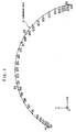
- interpolation points obtained by the secondary interpolation according to the conventional method are exemplified in a case where the primary interpolation is a circular interpolation (a motion path A designated by a program is circular).
- points P0, P1, P2 and P3 represent interpolation points determined by the primary interpolation. Those interpolation points are determined along the circular motion path.
- a linear interpolation is performed in the sections P0P1, P1P2 and P2P3 defined by the interpolation points P0, P1, P2, P3 obtained as the outputs of the primary interpolation.
- Points Q1 to Q23 represent interpolation points outputted in the secondary interpolation according to the conventional method.
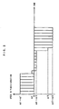
- FIG. 2 is a diagram for explaining the above, in which an example of feed rate of a Y axis is shown in the case where a motion command for each of X, Y and Z axes is outputted based on the output of the secondary interpolation in the conventional method.
- the direction of the Y axis corresponds to the direction of Y axis of a coordinate system shown in FIG. 1 (the Z axis is perpendicular to a plane of the sheet of FIG. 1.)
- the feed rate in sections Q0Q1, Q1Q2, Q2Q3, ..., Q21Q22, Q22Q23 is shown as a bar graph divided into twenty thee value areas.
- the feed rate in the Y-axis direction changes abruptly in the vicinity of the points P0, P1, P2 and P3.
- An object of the present invention is to mitigate the above problems
- a controller having a function of a numerical control for controlling a machine tool of each kind, a laser beam machine, a plasma machine or the like, so as to contribute improvement of machining accuracy and increase of machining speed of the machine controlled by the controller.
- the secondary interpolation is not performed to form a straight line but performed to form a smooth curve in the two-stage interpolation of the primary and secondary interpolations by software processing means included in the controller. Further, in the secondary interpolation processing, acceleration/deceleration control of speed in the tangential direction is performed to thereby restrain a path error and to effect smooth change of speed.
- a command analyzing section a primary interpolation section, a secondary interpolation section, an intermediate memory and an acceleration/deceleration control section are provided in the controller.
- the command analyzing section analyzes a program and converts the program to data for the primary interpolation section.
- the first interpolating section performs interpolation calculation in each first sampling period to obtain an interpolation point on a commanded path, and outputs the obtained interpolation point to the intermediate memory.
- the acceleration/deceleration control section performs acceleration/deceleration control based on the data stored in the intermediate memory, and calculates speed in each second sampling period.
- the secondary interpolation section defines a smooth curve based on output from the acceleration/deceleration control section and the data derived from the intermediate memory, and outputs an interpolation point on the smooth curve in each second sampling period.
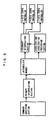
- FIG. 4 shows a example of a hardware structure of a controller of a machine according to the present invention.
- a processor 11 of a controller 10 reads a system program stored in a ROM 12 via a bus 21 and performs a general control of the controller 10 in accordance with the system program.
- a RAM 13 in the form of DRAM, etc. temporarily stores calculation data, display data and the like.
- a CMOS 14 stores the operation program and various parameters.
- the data stored in the CMOS 14 includes a software (programs and related parameters) for two-stage interpolation processing, as described later.
- the CMOS 14 is backed up by a battery (not shown) and functions as a non-volatile memory in which stored data is not deleted even when a power supply for the controller 10 is shut down.
- An interface 15 is provided for input/output between the controller 10 and an external device.
- An external device 31 such as an offline programming device or a printer is connected to the interface 15.
- the prepared data is inputted through the interface 15 to the controller 10.
- Data on a machining program edited by the controller 10 can be outputted by a printer.
- a PC (programmable controller) 16 is provided within the controller 10 and controls a machine in accordance with sequence programs in a ladder form. Specifically, the PC 16 converts commands to necessary signals by the sequence programs, and outputs the signals through an I/O unit 17 to the machine (in this example, a machine having the above mentioned four axes (X axis, Y axis, Z axis and A axis) according to M functions (miscellaneous functions), S functions (spindle speed functions) and T functions (tool functions) specified in machining programs. The outputted signals operate various actuating portions (air cylinders, screws, electric actuators, etc.) in the machine. Further, the PC 16 receives signals from various switches on the machine and an operation panel to perform the necessary processing on the signals and transmits them to the processor 1.
- M functions micellaneous functions
- S functions spindle speed functions
- T functions tool functions
- a graphic control circuit 18 converts digital data such as current position data of each axis (each of the four axes), an alarm, parameters and image data to graphic signals, and outputs the graphic signals.
- the graphic signals are transmitted to a display device 26 in a CRT/MDI unit 25 and displayed on the display device 26.
- An interface 19 receives data from a keyboard 27 of the CRT/MDI unit 25, and transmit the data to the processor 11.
- An interface 20 is connected to a manual pulse generator 32 and receives a pulse from the manual pulse generator 32.
- the manual pulse generator 32 is mounted on the machine operation panel, and used for manually moving/positioning movable parts of the machine including a working table.
- Axis control circuits 41 to 44 receive to process motion commands for the individual axes from the processor 11 and output the commands to servo amplifiers 51 to 54.
- the servo amplifiers 51 to 54 drive servomotors 61 to 64 for the individual axes in accordance with the motion commands.
- the servomotors 61 to 64 for the individual axes drive three basic axes (X axis, Y axis, Z axis) and a turning axis (A axis) of the machine.
- the A axis is provided for adjusting a orientation of the working table.
- Features of the present invention are applied in operation of the three basic axes (X axis, Y axis, Z axis).
- Reference numeral 644 denotes a pulse coder as a position detector provided in the servomotor 64 for driving the A axis. Pulse coders are provided in the servomotors for the other axes in the same way. Pulses outputted from the pulse coders are used as position feedback signals and speed feedback signals.
- a spindle control circuit 71 receives a spindle rotation command and outputs a spindle speed signal to a spindle amplifier 72. Receiving the spindle speed signal, the spindle amplifier 72 makes a spindle motor 73 rotate at the specified rotation speed to thereby operate the machining tool of the machine.
- the machine is a laser beam machine or a plasma machine
- the above mentioned components related to the spindle are not necessary, and known components for controlling a laser beam generator or a plasma torch is added instead.
- the hardware structure and the basic function of the controller of the present invention are not particularly different from those of a conventional numerical controller and the present invention does not require any special modification of the hardware structure or the basic function.
- a command analyzing section analyzes a command program and converts the program to data which is appropriate for use in a primary interpolation section.
- the primary interpolation section executes interpolation calculation in every first sampling period to obtain an interpolation point on a commanded path, and outputs the obtained interpolation point to an intermediate memory.
- Data stored in the intermediate memory includes a motion amount of each axis, a feed rate and a block length.
- An acceleration/deceleration control section performs acceleration/deceleration control based on the data in the intermediate memory to calculate speed in every second sampling period and outputs the calculated speed to a secondary interpolation section.
- the secondary interpolation section defines a smooth curve based on the output from the acceleration/deceleration control section and the data stored in the intermediate memory, and outputs a point on the smooth curve in every second sampling period.
- the second sampling period is determined to be shorter than the first sampling period. For example, the first sampling period is 8 ms and the second sampling period is 1 ms.
- Coordinates of an interpolation point within a segment is calculated using the following equations.
- a time parameter t takes values -L1, 0, L2 and (L2+L3) at the points P0, P1, P2 and P3, respectively, and the coefficients Ax, Bx, Cx, Dx, Ay, By, Cy and Dy are determined on the condition that the coordinates X(t), Y(t) take values of coordinates of points P0, P1, P2 and P3 at -L1, 0, L2 and (L2+L3), respectively.
- Secondary interpolation points within the segment P1P2 can be obtained by changing t in the following equation in the range of 0 ⁇ t ⁇ L2.
- X'(t) and Y'(t) respectively represent differentials of X(t) and Y(t) with respect to t.
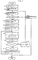
- Essentials of processing in each step are as follows:
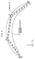
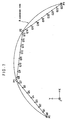
- FIG. 7 shows interpolation points defined in the above embodiment in the same manner as in FIG. 1.
- P1 to P3 are interpolation points outputted from the primary interpolation section
- Q0 to Q29 are interpolation points outputted from the secondary interpolation section.
- an actual moving path is made very close to a commanded path by performing the interpolation of smooth curve (in this example, a curve of third order).
- FIG. 8 shows change of speed of the Y axis in the above embodiment, in the same manner as in FIG. 2.
- Feed rate in individual sections Q0Q1, Q1Q2, Q2Q3, ..., Q27Q28, Q28Q29, over the entire moving path including a start point and a stop point is shown as a bar graph divided into twenty nine value areas. Since the sequence of points outputted by the secondary interpolation processing forms a smooth curve, there is no point where feed rate in the Y axis direction changes abruptly.
- Indications q5, q10, q15, q12 on the vertical axis indicate speed in sections Q4Q5, Q9Q10, Q14Q15, Q19Q20, respectively.
- a machine such as a machine tool of each kind, a laser beam machine or a plasma machine is controlled by a controller according to the present invention, it is possible to reduce a path error to a minor one and smoothly change speed of a machining tool. This makes it further possible to improve machining accuracy and increase machining speed.
Landscapes
- Engineering & Computer Science (AREA)
- Human Computer Interaction (AREA)
- Manufacturing & Machinery (AREA)
- Physics & Mathematics (AREA)
- General Physics & Mathematics (AREA)
- Automation & Control Theory (AREA)
- Computing Systems (AREA)
- Theoretical Computer Science (AREA)
- Numerical Control (AREA)
Applications Claiming Priority (3)
| Application Number | Priority Date | Filing Date | Title |
|---|---|---|---|
| JP329744/97 | 1997-11-14 | ||
| JP32974497 | 1997-11-14 | ||
| JP9329744A JPH11149306A (ja) | 1997-11-14 | 1997-11-14 | 加工機の制御装置 |
Publications (3)
| Publication Number | Publication Date |
|---|---|
| EP0917033A2 true EP0917033A2 (de) | 1999-05-19 |
| EP0917033A3 EP0917033A3 (de) | 2001-04-18 |
| EP0917033B1 EP0917033B1 (de) | 2004-10-06 |
Family
ID=18224807
Family Applications (1)
| Application Number | Title | Priority Date | Filing Date |
|---|---|---|---|
| EP98309336A Expired - Lifetime EP0917033B1 (de) | 1997-11-14 | 1998-11-13 | Maschinensteuerung |
Country Status (4)
| Country | Link |
|---|---|
| US (1) | US6401006B1 (de) |
| EP (1) | EP0917033B1 (de) |
| JP (1) | JPH11149306A (de) |
| DE (1) | DE69826808T2 (de) |
Cited By (11)
| Publication number | Priority date | Publication date | Assignee | Title |
|---|---|---|---|---|
| WO2001013188A3 (de) * | 1999-08-18 | 2002-03-28 | Bosch Gmbh Robert | Vorrichtung und verfahren zur sollwerte-erzeugung eines antriebs |
| US6401006B1 (en) * | 1997-11-14 | 2002-06-04 | Fanuc Ltd. | Machine controller with primary and secondary interpolation |
| WO2003014848A1 (de) * | 2001-08-11 | 2003-02-20 | Dr. Johannes Heidenhain Gmbh | ANORDNUNG ZUR ERZEUGUNG VON FÜHRUNGSGRÖssEN FÜR REGELKREISE EINER NUMERISCH GESTEUERTEN MASCHINE |
| ES2342795A1 (es) * | 2006-12-29 | 2010-07-14 | Universitat Politecnica De Catalunya | Metodo para la reduccion de la vibracion residual generada por una señal de excitacion o control transitoria mediante el ajuste del contenido frecuencial de dicha señal. |
| EP2629163A4 (de) * | 2010-10-13 | 2015-05-20 | Omron Tateisi Electronics Co | Steuervorrichtung, steuersystem und steuerverfahren |
| WO2016161884A1 (zh) * | 2015-04-09 | 2016-10-13 | 上海交通大学 | 开放式三维流道高速电弧放电层扫加工方法 |
| DE102013011684B4 (de) * | 2012-07-19 | 2017-09-07 | Fanuc Corporation | Numerische Steuervorrichtung, die eine Einfügeeinheit für Ecken mit mehreren Kurven umfasst |
| WO2017174800A1 (fr) | 2016-04-07 | 2017-10-12 | Willemin-Macodel Sa | Methode d'optimisation des programmes d'usinage |
| EP3460602A1 (de) * | 2017-09-22 | 2019-03-27 | Omron Corporation | Steuerungsvorrichtung, steuerungsverfahren und support-vorrichtung |
| CN114296400A (zh) * | 2021-11-16 | 2022-04-08 | 中南大学 | 一种用于激光切割高速插补的自适应前瞻处理方法 |
| EP4246257A1 (de) * | 2022-03-18 | 2023-09-20 | Siemens Aktiengesellschaft | Geschwindigkeitsabhängiges überschleifen zwischen sätzen mit unstetigen bahnverläufen |
Families Citing this family (32)
| Publication number | Priority date | Publication date | Assignee | Title |
|---|---|---|---|---|
| JP3034843B2 (ja) | 1998-05-28 | 2000-04-17 | ファナック株式会社 | 加工機の制御装置 |
| JP2000242321A (ja) * | 1999-02-19 | 2000-09-08 | Fujitsu Ltd | フィードバック制御装置、ディジタルフィルタ装置、および記憶装置 |
| US6922607B2 (en) * | 2000-12-06 | 2005-07-26 | Tsunehiko Yamazaki | Numerically controlled method |
| JP3592628B2 (ja) * | 2000-12-06 | 2004-11-24 | 恒彦 山崎 | 数値制御方法 |
| DE10104712C1 (de) * | 2001-02-02 | 2002-12-12 | Siemens Ag | Steuerungsverfahren sowie Regelungsstruktur zur Bewegungsführung, Vorsteuerung und Feininterpolation von Objekten in einem Drehzahlreglertakt, der schneller als der Lagereglertakt ist |
| US6677721B2 (en) * | 2001-02-02 | 2004-01-13 | Siemens Aktiengesellschaft | Method of control and control structure for the movement control, pre-control and fine interpolation of objects in a speed controller clock which is faster than the position controller clock |
| DE10164496A1 (de) * | 2001-12-28 | 2003-07-17 | Siemens Ag | Automatisierungssystem |
| US20040225382A1 (en) * | 2003-05-09 | 2004-11-11 | Phil Brown | Jerk profile, vector motion control and real time position capture in motion control systems |
| GB2418033B (en) * | 2003-06-02 | 2007-06-20 | Honda Motor Co Ltd | Teaching data preparing method for articulated robot |
| JP3830475B2 (ja) | 2003-08-05 | 2006-10-04 | ファナック株式会社 | 制御装置 |
| WO2006102517A2 (en) * | 2005-03-23 | 2006-09-28 | Hurco Companies, Inc. | Method of tolerance-based trajectory planning and control |
| JP4168060B2 (ja) * | 2006-04-24 | 2008-10-22 | ファナック株式会社 | 円錐状の加工面の加工を可能にした数値制御装置 |
| JP4801815B2 (ja) * | 2006-09-26 | 2011-10-26 | 本田技研工業株式会社 | 車両の自動操舵装置 |
| US7761442B1 (en) | 2007-03-29 | 2010-07-20 | Scientific Components Corporation | Database search system for high frequency electronic components |
| US7739260B1 (en) | 2006-12-28 | 2010-06-15 | Scientific Components Corporation | Database search system using interpolated data with defined resolution |
| US8417502B1 (en) | 2006-12-28 | 2013-04-09 | Scientific Components Corporation | Mixer harmonics calculator |
| JP5009010B2 (ja) * | 2007-03-13 | 2012-08-22 | 新日本工機株式会社 | 数値制御装置 |
| US8214415B2 (en) * | 2008-04-18 | 2012-07-03 | Motion Engineering Incorporated | Interpolator for a networked motion control system |
| EP2336839A4 (de) | 2008-09-16 | 2013-11-06 | Shin Nippon Koki Co Ltd | Numerische steuerung |
| US9921712B2 (en) | 2010-12-29 | 2018-03-20 | Mako Surgical Corp. | System and method for providing substantially stable control of a surgical tool |
| US9119655B2 (en) | 2012-08-03 | 2015-09-01 | Stryker Corporation | Surgical manipulator capable of controlling a surgical instrument in multiple modes |
| JP2012253492A (ja) * | 2011-06-01 | 2012-12-20 | Sony Corp | 画像処理装置、画像処理方法、及びプログラム |
| JP5439548B2 (ja) * | 2012-06-29 | 2014-03-12 | 新日本工機株式会社 | 加工指令変換プログラム、記憶媒体及び加工指令変換装置 |
| US9226796B2 (en) | 2012-08-03 | 2016-01-05 | Stryker Corporation | Method for detecting a disturbance as an energy applicator of a surgical instrument traverses a cutting path |
| KR102397265B1 (ko) | 2012-08-03 | 2022-05-12 | 스트리커 코포레이션 | 로봇 수술을 위한 시스템 및 방법 |
| US9820818B2 (en) | 2012-08-03 | 2017-11-21 | Stryker Corporation | System and method for controlling a surgical manipulator based on implant parameters |
| CN103454979B (zh) * | 2013-09-11 | 2015-07-22 | 大连理工计算机控制工程有限公司 | 一种封装成PLCOpen指令的变速曲线圆弧快速插补方法 |
| CN103934528B (zh) * | 2014-04-14 | 2016-02-10 | 上海交通大学 | 一种用于电火花加工的六轴联动插补方法 |
| JP6386511B2 (ja) * | 2016-10-28 | 2018-09-05 | ファナック株式会社 | 工具経路生成装置、工具経路生成方法及び工具経路生成プログラム |
| US11202682B2 (en) | 2016-12-16 | 2021-12-21 | Mako Surgical Corp. | Techniques for modifying tool operation in a surgical robotic system based on comparing actual and commanded states of the tool relative to a surgical site |
| DE102017008748A1 (de) * | 2017-09-19 | 2019-03-21 | Innolite Gmbh | Software-Baustein, Präzisionsmaschine, Verfahren und Bauteil |
| CN110716493B (zh) * | 2019-09-10 | 2022-03-04 | 天津大学 | 一种五轴微线段加工路径光顺方法 |
Family Cites Families (21)
| Publication number | Priority date | Publication date | Assignee | Title |
|---|---|---|---|---|
| JPS6040042B2 (ja) * | 1975-07-17 | 1985-09-09 | 日本電気株式会社 | 高速・高精度補間方法 |
| JPS5962909A (ja) * | 1982-10-01 | 1984-04-10 | Fanuc Ltd | 加減速装置 |
| JPS62204312A (ja) * | 1986-03-05 | 1987-09-09 | Hitachi Denshi Ltd | 数値制御装置のパルス分配方法 |
| DE3640987C1 (de) * | 1986-12-01 | 1993-04-29 | Agie Ag Ind Elektronik | Numerisches Steuersystem fuer hochdynamische Prozesse |
| JPH0199102A (ja) * | 1987-10-13 | 1989-04-18 | Yamatake Honeywell Co Ltd | サーボ制御装置 |
| JPH01217608A (ja) | 1988-02-26 | 1989-08-31 | Fanuc Ltd | スプライン曲線生成方法 |
| JP2613784B2 (ja) * | 1988-03-16 | 1997-05-28 | 三菱電機株式会社 | 補間装置 |
| JPH02113305A (ja) | 1988-10-24 | 1990-04-25 | Fanuc Ltd | スプライン補間方法 |
| JPH02162402A (ja) * | 1988-12-15 | 1990-06-22 | Komatsu Ltd | ロボット軌道制御のスムージング処理方法 |
| DE69024297T2 (de) * | 1989-02-23 | 1996-08-29 | Yaskawa Denki Seisakusho Kk | Verfahren und gerät zum mehrschichtigen auftragschweissen |
| JP2935713B2 (ja) * | 1989-08-22 | 1999-08-16 | ファナック株式会社 | 数値制御装置 |
| US5229698A (en) * | 1990-08-06 | 1993-07-20 | Cincinnati Milacron Inc. | Method and apparatus for sub-span interpolation |
| JPH04131913A (ja) * | 1990-09-25 | 1992-05-06 | Toyoda Mach Works Ltd | ロボット制御装置 |
| JPH06180606A (ja) * | 1992-12-11 | 1994-06-28 | Mitsubishi Electric Corp | 駆動対象物の制御装置 |
| US5508596A (en) * | 1993-10-07 | 1996-04-16 | Omax Corporation | Motion control with precomputation |
| EP0783731B1 (de) | 1994-09-29 | 1999-05-06 | Siemens Aktiengesellschaft | Verfahren zur konturfehlerfreien begrenzung von achsbeschleunigungen |
| JPH08292809A (ja) * | 1995-04-20 | 1996-11-05 | Mitsubishi Electric Corp | 数値制御方法および数値制御装置 |
| JP3476287B2 (ja) * | 1995-08-31 | 2003-12-10 | ファナック株式会社 | ロボットの接続動作時に速度制御を行なうための曲線補間方法 |
| JPH09244725A (ja) * | 1996-03-05 | 1997-09-19 | Sony Corp | 軌道補間装置及びその方法並びに制御装置 |
| JPH11143519A (ja) * | 1997-11-07 | 1999-05-28 | Fanuc Ltd | 数値制御における加減速制御方法および数値制御装置 |
| JPH11149306A (ja) * | 1997-11-14 | 1999-06-02 | Fanuc Ltd | 加工機の制御装置 |
-
1997
- 1997-11-14 JP JP9329744A patent/JPH11149306A/ja active Pending
-
1998
- 1998-11-13 DE DE69826808T patent/DE69826808T2/de not_active Expired - Lifetime
- 1998-11-13 EP EP98309336A patent/EP0917033B1/de not_active Expired - Lifetime
- 1998-11-13 US US09/191,127 patent/US6401006B1/en not_active Expired - Fee Related
Cited By (17)
| Publication number | Priority date | Publication date | Assignee | Title |
|---|---|---|---|---|
| US6401006B1 (en) * | 1997-11-14 | 2002-06-04 | Fanuc Ltd. | Machine controller with primary and secondary interpolation |
| WO2001013188A3 (de) * | 1999-08-18 | 2002-03-28 | Bosch Gmbh Robert | Vorrichtung und verfahren zur sollwerte-erzeugung eines antriebs |
| WO2003014848A1 (de) * | 2001-08-11 | 2003-02-20 | Dr. Johannes Heidenhain Gmbh | ANORDNUNG ZUR ERZEUGUNG VON FÜHRUNGSGRÖssEN FÜR REGELKREISE EINER NUMERISCH GESTEUERTEN MASCHINE |
| US6772020B2 (en) | 2001-08-11 | 2004-08-03 | Johannes Heidenhain Gmbh | Arrangement for generating command variables for control loops of a numerically controlled machine |
| ES2342795A1 (es) * | 2006-12-29 | 2010-07-14 | Universitat Politecnica De Catalunya | Metodo para la reduccion de la vibracion residual generada por una señal de excitacion o control transitoria mediante el ajuste del contenido frecuencial de dicha señal. |
| ES2342795B1 (es) * | 2006-12-29 | 2011-04-26 | Universitat Politècnica De Catalunya | Metodo para la reduccion de la vibracion residual generada por una señal de excitacion o control transitoria mediante el ajuste del contenido frecuencial de dicha señal. |
| US9606524B2 (en) | 2010-10-13 | 2017-03-28 | Omron Corporation | Control apparatus, control system and control method |
| EP2629163A4 (de) * | 2010-10-13 | 2015-05-20 | Omron Tateisi Electronics Co | Steuervorrichtung, steuersystem und steuerverfahren |
| DE102013011684B4 (de) * | 2012-07-19 | 2017-09-07 | Fanuc Corporation | Numerische Steuervorrichtung, die eine Einfügeeinheit für Ecken mit mehreren Kurven umfasst |
| WO2016161884A1 (zh) * | 2015-04-09 | 2016-10-13 | 上海交通大学 | 开放式三维流道高速电弧放电层扫加工方法 |
| WO2017174800A1 (fr) | 2016-04-07 | 2017-10-12 | Willemin-Macodel Sa | Methode d'optimisation des programmes d'usinage |
| US10613516B2 (en) | 2016-04-07 | 2020-04-07 | Willemin-Macodel Sa | Method of optimization of machining programs |
| EP3460602A1 (de) * | 2017-09-22 | 2019-03-27 | Omron Corporation | Steuerungsvorrichtung, steuerungsverfahren und support-vorrichtung |
| CN114296400A (zh) * | 2021-11-16 | 2022-04-08 | 中南大学 | 一种用于激光切割高速插补的自适应前瞻处理方法 |
| CN114296400B (zh) * | 2021-11-16 | 2024-03-12 | 中南大学 | 一种用于激光切割高速插补的自适应前瞻处理方法 |
| EP4246257A1 (de) * | 2022-03-18 | 2023-09-20 | Siemens Aktiengesellschaft | Geschwindigkeitsabhängiges überschleifen zwischen sätzen mit unstetigen bahnverläufen |
| WO2023174637A1 (de) * | 2022-03-18 | 2023-09-21 | Siemens Aktiengesellschaft | Geschwindigkeitsabhängiges überschleifen zwischen sätzen mit unstetigen bahnverläufen |
Also Published As
| Publication number | Publication date |
|---|---|
| US6401006B1 (en) | 2002-06-04 |
| DE69826808D1 (de) | 2004-11-11 |
| JPH11149306A (ja) | 1999-06-02 |
| DE69826808T2 (de) | 2005-02-17 |
| EP0917033B1 (de) | 2004-10-06 |
| EP0917033A3 (de) | 2001-04-18 |
Similar Documents
| Publication | Publication Date | Title |
|---|---|---|
| EP0917033B1 (de) | Maschinensteuerung | |
| US6539275B1 (en) | Machine controller and process with two-step interpolation | |
| EP0440805B1 (de) | Vorschubgeschwindigkeitskontrolle | |
| KR100710852B1 (ko) | 공작기계의 수치제어장치 및 제어방법 | |
| Martinov et al. | Method of decomposition and synthesis of the custom CNC systems | |
| EP0557530A1 (de) | Numerische steuerungseinrichtung | |
| WO1995004316A1 (en) | Method and system for estimating robot tool center point speed | |
| JP3037881B2 (ja) | 数値制御装置 | |
| JPH0736514A (ja) | 3次元工具径補正方式 | |
| US5181178A (en) | Spindle control command method | |
| JPH11237920A (ja) | Nc工作機械の制御装置および位置決め制御方法 | |
| JP7614235B2 (ja) | 数値制御装置 | |
| EP0417307A1 (de) | Zeichnungsverfahren für numerische datenprogramme | |
| WO1988008354A1 (fr) | Procede de regulation de la puissance d'une machine-outil a laser avec unite de commande numerique | |
| JPH0266604A (ja) | 数値制御装置 | |
| JP3445474B2 (ja) | 位置制御装置および位置制御方法 | |
| JPH09190211A (ja) | 数値制御装置の経路制御方式 | |
| JPH07210225A (ja) | 数値制御装置 | |
| JP4982170B2 (ja) | 加工制御装置および加工制御プログラム | |
| EP0463176A1 (de) | Steuersystem zur umwandlung dreidimensionaler koordinaten | |
| JPH0258106A (ja) | 加減速時定数制御方式 | |
| JPH0346006A (ja) | 数値制御装置の軌跡制御方法 | |
| JPH0887312A (ja) | 円筒補間方式 | |
| JP3201758B2 (ja) | バックラッシ補正方法 | |
| KR0151016B1 (ko) | 서보 모터의 가감속 제어 방법 |
Legal Events
| Date | Code | Title | Description |
|---|---|---|---|
| PUAI | Public reference made under article 153(3) epc to a published international application that has entered the european phase |
Free format text: ORIGINAL CODE: 0009012 |
|
| AK | Designated contracting states |
Kind code of ref document: A2 Designated state(s): DE |
|
| AX | Request for extension of the european patent |
Free format text: AL;LT;LV;MK;RO;SI |
|
| PUAL | Search report despatched |
Free format text: ORIGINAL CODE: 0009013 |
|
| AK | Designated contracting states |
Kind code of ref document: A3 Designated state(s): AT BE CH CY DE DK ES FI FR GB GR IE IT LI LU MC NL PT SE |
|
| AX | Request for extension of the european patent |
Free format text: AL;LT;LV;MK;RO;SI |
|
| 17P | Request for examination filed |
Effective date: 20010806 |
|
| AKX | Designation fees paid |
Free format text: DE |
|
| 17Q | First examination report despatched |
Effective date: 20021210 |
|
| GRAP | Despatch of communication of intention to grant a patent |
Free format text: ORIGINAL CODE: EPIDOSNIGR1 |
|
| RAP1 | Party data changed (applicant data changed or rights of an application transferred) |
Owner name: FANUC LTD |
|
| GRAS | Grant fee paid |
Free format text: ORIGINAL CODE: EPIDOSNIGR3 |
|
| GRAA | (expected) grant |
Free format text: ORIGINAL CODE: 0009210 |
|
| AK | Designated contracting states |
Kind code of ref document: B1 Designated state(s): DE |
|
| REF | Corresponds to: |
Ref document number: 69826808 Country of ref document: DE Date of ref document: 20041111 Kind code of ref document: P |
|
| PLBE | No opposition filed within time limit |
Free format text: ORIGINAL CODE: 0009261 |
|
| STAA | Information on the status of an ep patent application or granted ep patent |
Free format text: STATUS: NO OPPOSITION FILED WITHIN TIME LIMIT |
|
| 26N | No opposition filed |
Effective date: 20050707 |
|
| PGFP | Annual fee paid to national office [announced via postgrant information from national office to epo] |
Ref country code: DE Payment date: 20101110 Year of fee payment: 13 |
|
| REG | Reference to a national code |
Ref country code: DE Ref legal event code: R119 Ref document number: 69826808 Country of ref document: DE Effective date: 20130601 |
|
| PG25 | Lapsed in a contracting state [announced via postgrant information from national office to epo] |
Ref country code: DE Free format text: LAPSE BECAUSE OF NON-PAYMENT OF DUE FEES Effective date: 20130601 |