EP0917033A2 - Controller for machine - Google Patents
Controller for machine Download PDFInfo
- Publication number
- EP0917033A2 EP0917033A2 EP98309336A EP98309336A EP0917033A2 EP 0917033 A2 EP0917033 A2 EP 0917033A2 EP 98309336 A EP98309336 A EP 98309336A EP 98309336 A EP98309336 A EP 98309336A EP 0917033 A2 EP0917033 A2 EP 0917033A2
- Authority
- EP
- European Patent Office
- Prior art keywords
- interpolation
- primary
- acceleration
- controller
- deceleration control
- Prior art date
- Legal status (The legal status is an assumption and is not a legal conclusion. Google has not performed a legal analysis and makes no representation as to the accuracy of the status listed.)
- Granted
Links
Images


Classifications
-
- G—PHYSICS
- G05—CONTROLLING; REGULATING
- G05B—CONTROL OR REGULATING SYSTEMS IN GENERAL; FUNCTIONAL ELEMENTS OF SUCH SYSTEMS; MONITORING OR TESTING ARRANGEMENTS FOR SUCH SYSTEMS OR ELEMENTS
- G05B19/00—Programme-control systems
- G05B19/02—Programme-control systems electric
- G05B19/18—Numerical control [NC], i.e. automatically operating machines, in particular machine tools, e.g. in a manufacturing environment, so as to execute positioning, movement or co-ordinated operations by means of programme data in numerical form
- G05B19/41—Numerical control [NC], i.e. automatically operating machines, in particular machine tools, e.g. in a manufacturing environment, so as to execute positioning, movement or co-ordinated operations by means of programme data in numerical form characterised by interpolation, e.g. the computation of intermediate points between programmed end points to define the path to be followed and the rate of travel along that path
- G05B19/4103—Digital interpolation
-
- G—PHYSICS
- G05—CONTROLLING; REGULATING
- G05B—CONTROL OR REGULATING SYSTEMS IN GENERAL; FUNCTIONAL ELEMENTS OF SUCH SYSTEMS; MONITORING OR TESTING ARRANGEMENTS FOR SUCH SYSTEMS OR ELEMENTS
- G05B19/00—Programme-control systems
- G05B19/02—Programme-control systems electric
- G05B19/18—Numerical control [NC], i.e. automatically operating machines, in particular machine tools, e.g. in a manufacturing environment, so as to execute positioning, movement or co-ordinated operations by means of programme data in numerical form
- G05B19/416—Numerical control [NC], i.e. automatically operating machines, in particular machine tools, e.g. in a manufacturing environment, so as to execute positioning, movement or co-ordinated operations by means of programme data in numerical form characterised by control of velocity, acceleration or deceleration
Definitions
- the present invention relates to a controller for controlling a machine such as a general machine tool, a laser beam machine or a plasma machine in which respective axes are driven by servomotors, and more specifically to a technique for improving machining accuracy and machining speed of the machine controlled by the controller.
- a machining tool of various kinds for example, a cutting tool, a drilling tool, a laser beam nozzle or a plasma torch
- a machining tool of various kinds for example, a cutting tool, a drilling tool, a laser beam nozzle or a plasma torch
- the servomotor for each axis is controlled by a servo control section (including a servo CPU and a servo amplifier) provided for each axis.
- a servo control section including a servo CPU and a servo amplifier
- Each servo control section controls the servomotor based on a motion command outputted for each axis from the controller of the machine, and a position and speed feedback signals from a pulse encoder provided for each servomotor or axis.
- the controller reads a program in which a motion path of the machining tool is specified, and performs an interpolation calculation to determine a plurality of interpolation points along the motion path by software processing.
- interpolation calculation there is known a method in which interpolation calculation is divided into two stages. The two stages are respectively called a primary interpolation and a secondary interpolation.
- the primary interpolation interpolation points are defined on the motion path in a predetermined sampling period (first sampling period).
- the secondary interpolation further interpolates the interpolation points defined by the primary interpolation.
- the secondary interpolation is performed on a straight line connecting the interpolation points defined by the primary interpolation.
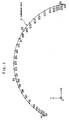
- interpolation points obtained by the secondary interpolation according to the conventional method are exemplified in a case where the primary interpolation is a circular interpolation (a motion path A designated by a program is circular).
- points P0, P1, P2 and P3 represent interpolation points determined by the primary interpolation. Those interpolation points are determined along the circular motion path.
- a linear interpolation is performed in the sections P0P1, P1P2 and P2P3 defined by the interpolation points P0, P1, P2, P3 obtained as the outputs of the primary interpolation.
- Points Q1 to Q23 represent interpolation points outputted in the secondary interpolation according to the conventional method.
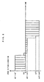
- FIG. 2 is a diagram for explaining the above, in which an example of feed rate of a Y axis is shown in the case where a motion command for each of X, Y and Z axes is outputted based on the output of the secondary interpolation in the conventional method.
- the direction of the Y axis corresponds to the direction of Y axis of a coordinate system shown in FIG. 1 (the Z axis is perpendicular to a plane of the sheet of FIG. 1.)
- the feed rate in sections Q0Q1, Q1Q2, Q2Q3, ..., Q21Q22, Q22Q23 is shown as a bar graph divided into twenty thee value areas.
- the feed rate in the Y-axis direction changes abruptly in the vicinity of the points P0, P1, P2 and P3.
- An object of the present invention is to mitigate the above problems
- a controller having a function of a numerical control for controlling a machine tool of each kind, a laser beam machine, a plasma machine or the like, so as to contribute improvement of machining accuracy and increase of machining speed of the machine controlled by the controller.
- the secondary interpolation is not performed to form a straight line but performed to form a smooth curve in the two-stage interpolation of the primary and secondary interpolations by software processing means included in the controller. Further, in the secondary interpolation processing, acceleration/deceleration control of speed in the tangential direction is performed to thereby restrain a path error and to effect smooth change of speed.
- a command analyzing section a primary interpolation section, a secondary interpolation section, an intermediate memory and an acceleration/deceleration control section are provided in the controller.
- the command analyzing section analyzes a program and converts the program to data for the primary interpolation section.
- the first interpolating section performs interpolation calculation in each first sampling period to obtain an interpolation point on a commanded path, and outputs the obtained interpolation point to the intermediate memory.
- the acceleration/deceleration control section performs acceleration/deceleration control based on the data stored in the intermediate memory, and calculates speed in each second sampling period.
- the secondary interpolation section defines a smooth curve based on output from the acceleration/deceleration control section and the data derived from the intermediate memory, and outputs an interpolation point on the smooth curve in each second sampling period.
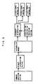
- FIG. 4 shows a example of a hardware structure of a controller of a machine according to the present invention.
- a processor 11 of a controller 10 reads a system program stored in a ROM 12 via a bus 21 and performs a general control of the controller 10 in accordance with the system program.
- a RAM 13 in the form of DRAM, etc. temporarily stores calculation data, display data and the like.
- a CMOS 14 stores the operation program and various parameters.
- the data stored in the CMOS 14 includes a software (programs and related parameters) for two-stage interpolation processing, as described later.
- the CMOS 14 is backed up by a battery (not shown) and functions as a non-volatile memory in which stored data is not deleted even when a power supply for the controller 10 is shut down.
- An interface 15 is provided for input/output between the controller 10 and an external device.
- An external device 31 such as an offline programming device or a printer is connected to the interface 15.
- the prepared data is inputted through the interface 15 to the controller 10.
- Data on a machining program edited by the controller 10 can be outputted by a printer.
- a PC (programmable controller) 16 is provided within the controller 10 and controls a machine in accordance with sequence programs in a ladder form. Specifically, the PC 16 converts commands to necessary signals by the sequence programs, and outputs the signals through an I/O unit 17 to the machine (in this example, a machine having the above mentioned four axes (X axis, Y axis, Z axis and A axis) according to M functions (miscellaneous functions), S functions (spindle speed functions) and T functions (tool functions) specified in machining programs. The outputted signals operate various actuating portions (air cylinders, screws, electric actuators, etc.) in the machine. Further, the PC 16 receives signals from various switches on the machine and an operation panel to perform the necessary processing on the signals and transmits them to the processor 1.
- M functions micellaneous functions
- S functions spindle speed functions
- T functions tool functions
- a graphic control circuit 18 converts digital data such as current position data of each axis (each of the four axes), an alarm, parameters and image data to graphic signals, and outputs the graphic signals.
- the graphic signals are transmitted to a display device 26 in a CRT/MDI unit 25 and displayed on the display device 26.
- An interface 19 receives data from a keyboard 27 of the CRT/MDI unit 25, and transmit the data to the processor 11.
- An interface 20 is connected to a manual pulse generator 32 and receives a pulse from the manual pulse generator 32.
- the manual pulse generator 32 is mounted on the machine operation panel, and used for manually moving/positioning movable parts of the machine including a working table.
- Axis control circuits 41 to 44 receive to process motion commands for the individual axes from the processor 11 and output the commands to servo amplifiers 51 to 54.
- the servo amplifiers 51 to 54 drive servomotors 61 to 64 for the individual axes in accordance with the motion commands.
- the servomotors 61 to 64 for the individual axes drive three basic axes (X axis, Y axis, Z axis) and a turning axis (A axis) of the machine.
- the A axis is provided for adjusting a orientation of the working table.
- Features of the present invention are applied in operation of the three basic axes (X axis, Y axis, Z axis).
- Reference numeral 644 denotes a pulse coder as a position detector provided in the servomotor 64 for driving the A axis. Pulse coders are provided in the servomotors for the other axes in the same way. Pulses outputted from the pulse coders are used as position feedback signals and speed feedback signals.
- a spindle control circuit 71 receives a spindle rotation command and outputs a spindle speed signal to a spindle amplifier 72. Receiving the spindle speed signal, the spindle amplifier 72 makes a spindle motor 73 rotate at the specified rotation speed to thereby operate the machining tool of the machine.
- the machine is a laser beam machine or a plasma machine
- the above mentioned components related to the spindle are not necessary, and known components for controlling a laser beam generator or a plasma torch is added instead.
- the hardware structure and the basic function of the controller of the present invention are not particularly different from those of a conventional numerical controller and the present invention does not require any special modification of the hardware structure or the basic function.
- a command analyzing section analyzes a command program and converts the program to data which is appropriate for use in a primary interpolation section.
- the primary interpolation section executes interpolation calculation in every first sampling period to obtain an interpolation point on a commanded path, and outputs the obtained interpolation point to an intermediate memory.
- Data stored in the intermediate memory includes a motion amount of each axis, a feed rate and a block length.
- An acceleration/deceleration control section performs acceleration/deceleration control based on the data in the intermediate memory to calculate speed in every second sampling period and outputs the calculated speed to a secondary interpolation section.
- the secondary interpolation section defines a smooth curve based on the output from the acceleration/deceleration control section and the data stored in the intermediate memory, and outputs a point on the smooth curve in every second sampling period.
- the second sampling period is determined to be shorter than the first sampling period. For example, the first sampling period is 8 ms and the second sampling period is 1 ms.
- Coordinates of an interpolation point within a segment is calculated using the following equations.
- a time parameter t takes values -L1, 0, L2 and (L2+L3) at the points P0, P1, P2 and P3, respectively, and the coefficients Ax, Bx, Cx, Dx, Ay, By, Cy and Dy are determined on the condition that the coordinates X(t), Y(t) take values of coordinates of points P0, P1, P2 and P3 at -L1, 0, L2 and (L2+L3), respectively.
- Secondary interpolation points within the segment P1P2 can be obtained by changing t in the following equation in the range of 0 ⁇ t ⁇ L2.
- X'(t) and Y'(t) respectively represent differentials of X(t) and Y(t) with respect to t.
- Essentials of processing in each step are as follows:
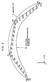
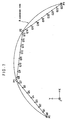
- FIG. 7 shows interpolation points defined in the above embodiment in the same manner as in FIG. 1.
- P1 to P3 are interpolation points outputted from the primary interpolation section
- Q0 to Q29 are interpolation points outputted from the secondary interpolation section.
- an actual moving path is made very close to a commanded path by performing the interpolation of smooth curve (in this example, a curve of third order).
- FIG. 8 shows change of speed of the Y axis in the above embodiment, in the same manner as in FIG. 2.
- Feed rate in individual sections Q0Q1, Q1Q2, Q2Q3, ..., Q27Q28, Q28Q29, over the entire moving path including a start point and a stop point is shown as a bar graph divided into twenty nine value areas. Since the sequence of points outputted by the secondary interpolation processing forms a smooth curve, there is no point where feed rate in the Y axis direction changes abruptly.
- Indications q5, q10, q15, q12 on the vertical axis indicate speed in sections Q4Q5, Q9Q10, Q14Q15, Q19Q20, respectively.
- a machine such as a machine tool of each kind, a laser beam machine or a plasma machine is controlled by a controller according to the present invention, it is possible to reduce a path error to a minor one and smoothly change speed of a machining tool. This makes it further possible to improve machining accuracy and increase machining speed.
Abstract
Description
- The present invention relates to a controller for controlling a machine such as a general machine tool, a laser beam machine or a plasma machine in which respective axes are driven by servomotors, and more specifically to a technique for improving machining accuracy and machining speed of the machine controlled by the controller.
- In a machine tool, a laser beam machine or a plasma machine, a machining tool of various kinds (for example, a cutting tool, a drilling tool, a laser beam nozzle or a plasma torch) is attached to a machining head and respective axes for moving the machining bead or a working table which moves relatively to the machining head are driven by servomotors.
- The servomotor for each axis is controlled by a servo control section (including a servo CPU and a servo amplifier) provided for each axis. Each servo control section controls the servomotor based on a motion command outputted for each axis from the controller of the machine, and a position and speed feedback signals from a pulse encoder provided for each servomotor or axis.
- The controller reads a program in which a motion path of the machining tool is specified, and performs an interpolation calculation to determine a plurality of interpolation points along the motion path by software processing. With respect to the interpolation calculation, there is known a method in which interpolation calculation is divided into two stages. The two stages are respectively called a primary interpolation and a secondary interpolation. In the primary interpolation, interpolation points are defined on the motion path in a predetermined sampling period (first sampling period). The secondary interpolation further interpolates the interpolation points defined by the primary interpolation. According to the conventional method, the secondary interpolation is performed on a straight line connecting the interpolation points defined by the primary interpolation.
- In FIG. 1, interpolation points obtained by the secondary interpolation according to the conventional method are exemplified in a case where the primary interpolation is a circular interpolation (a motion path A designated by a program is circular). In FIG. 1, points P0, P1, P2 and P3 represent interpolation points determined by the primary interpolation. Those interpolation points are determined along the circular motion path. In the conventional method of the secondary interpolation to be performed subsequently to the primary interpolation, a linear interpolation is performed in the sections P0P1, P1P2 and P2P3 defined by the interpolation points P0, P1, P2, P3 obtained as the outputs of the primary interpolation. Points Q1 to Q23 represent interpolation points outputted in the secondary interpolation according to the conventional method.
- As is understood from the example of FIG. 1, when the secondary interpolation is performed as linear interpolation, speed of each axis changes abruptly in the vicinity of the interpolation points P0, P1, P2, P3 defined by the primary interpolation. Since the speed does not change smoothly, a problem such as deterioration in surface roughness of a machined surface arises in an actual machining.
- Further, since the secondary interpolation is performed based on speed data derived from the output of the primary interpolation, speed changes abruptly at the time of starting and stopping of the motion or passing a point where a feed rate changes. FIG. 2 is a diagram for explaining the above, in which an example of feed rate of a Y axis is shown in the case where a motion command for each of X, Y and Z axes is outputted based on the output of the secondary interpolation in the conventional method. The direction of the Y axis corresponds to the direction of Y axis of a coordinate system shown in FIG. 1 (the Z axis is perpendicular to a plane of the sheet of FIG. 1.)
- In FIG. 2, the feed rate in sections Q0Q1, Q1Q2, Q2Q3, ..., Q21Q22, Q22Q23 is shown as a bar graph divided into twenty thee value areas. In the example of FIG. 1, since a sequence of points outputted by the secondary interpolation aligns on three straight-line sections connected to form a polygonal line, the feed rate in the Y-axis direction changes abruptly in the vicinity of the points P0, P1, P2 and P3. When speed in a section Qi-1Qi (i=1, 2, 3, ..., 23) is represented by Qi, the feed rate abruptly changes 0 →q1 at the time of starting of motion from P0; q7 → q8 and q8 → q9 before and after passing the point P1; q15 → q16 and q16 → q17 before and after passing the point P2; and P23 → 0 at the time of stopping.
- When left as it is, the feed rate of each axis does not change smoothly. Therefore, acceleration/deceleration processing is generally performed on speed data for each axis after the secondary interpolation in order to ensure that the feed rate changes smoothly. However, when each axis is controlled by the acceleration/deceleration processing on the speed data, a path error is produced such that the resulting path for the machining tool deviates inwards from the commanded path. In the example shown in FIGS. 1 and 2, the resulting path will be a path B as shown in FIG. 3 with respect to the motion path A specified by the program.
- The above described problems (abrupt change of the feed rate and a path error by the acceleration/deceleration control) are conspicuous especially when the machining speed is high. Therefore, in the controller which performs the two-stage interpolation in conventional method, these problems hinder not only improvement of machining accuracy but also increase of machining speed.
- An object of the present invention is to mitigate the above problems In a controller (having a function of a numerical control) for controlling a machine tool of each kind, a laser beam machine, a plasma machine or the like, so as to contribute improvement of machining accuracy and increase of machining speed of the machine controlled by the controller.
- In the present invention, the secondary interpolation is not performed to form a straight line but performed to form a smooth curve in the two-stage interpolation of the primary and secondary interpolations by software processing means included in the controller. Further, in the secondary interpolation processing, acceleration/deceleration control of speed in the tangential direction is performed to thereby restrain a path error and to effect smooth change of speed.
- Specifically, according to the present invention, since the secondary interpolation of the two-stage interpolation is not performed on a straight line but performed on a smooth curve, change of speed on each axis is smooth. Further, since the acceleration/deceleration control is performed so that speed in the tangential direction changes smoothly, change of speed is smooth even at the time of stating and stopping of the motion or passing a point where feed rate changes.
- In a preferred embodiment of the invention, a command analyzing section, a primary interpolation section, a secondary interpolation section, an intermediate memory and an acceleration/deceleration control section are provided in the controller.
- The command analyzing section analyzes a program and converts the program to data for the primary interpolation section. The first interpolating section performs interpolation calculation in each first sampling period to obtain an interpolation point on a commanded path, and outputs the obtained interpolation point to the intermediate memory. The acceleration/deceleration control section performs acceleration/deceleration control based on the data stored in the intermediate memory, and calculates speed in each second sampling period. The secondary interpolation section defines a smooth curve based on output from the acceleration/deceleration control section and the data derived from the intermediate memory, and outputs an interpolation point on the smooth curve in each second sampling period.
-
- FIG. 1 is a diagram showing interpolation points for explanation of secondary interpolation according to a conventional methd in the case where primary interpolation is circular interpolation (a motion path A specified by a program is circular);
- FIG. 2 is a diagram for showing change of speed in the conventional method;
- FIG. 3 shows a resulting path B with respect to a motion path A specfied by a machining program in the example shown in FIGS. 1 and 2;
- FIG. 4 is a block diagram schematically showing a hardware structure of a controller for a machine according to an embodiment of the invention;
- FIG. 5 is a diagram showing block structure of the controller according to the embodiment from a view point of software processing;
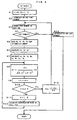
- FIG. 6 is a flowchart schematically showing processing for a smooth secondary interpolation using equations of third degree in the embodiment;
- FIG. 7 is a diagram showing interpolation points obtained in the embodiment in the same manner as in FIG. 1; and
- FIG. 8 is a diagram showing change of speed of Y axis in the embodiment in the same manner as in FIG. 2.
-
- FIG. 4 shows a example of a hardware structure of a controller of a machine according to the present invention. In FIG. 4, a processor 11 of a controller 10 reads a system program stored in a ROM 12 via a bus 21 and performs a general control of the controller 10 in accordance with the system program. A RAM 13 in the form of DRAM, etc. temporarily stores calculation data, display data and the like.
- A CMOS 14 stores the operation program and various parameters. The data stored in the CMOS 14 includes a software (programs and related parameters) for two-stage interpolation processing, as described later.
- The CMOS 14 is backed up by a battery (not shown) and functions as a non-volatile memory in which stored data is not deleted even when a power supply for the controller 10 is shut down.
- An interface 15 is provided for input/output between the controller 10 and an external device. An external device 31 such as an offline programming device or a printer is connected to the interface 15. When a machining program is prepared by a offline programming device, the prepared data is inputted through the interface 15 to the controller 10. Data on a machining program edited by the controller 10 can be outputted by a printer.
- A PC (programmable controller) 16 is provided within the controller 10 and controls a machine in accordance with sequence programs in a ladder form. Specifically, the PC 16 converts commands to necessary signals by the sequence programs, and outputs the signals through an I/O unit 17 to the machine (in this example, a machine having the above mentioned four axes (X axis, Y axis, Z axis and A axis) according to M functions (miscellaneous functions), S functions (spindle speed functions) and T functions (tool functions) specified in machining programs. The outputted signals operate various actuating portions (air cylinders, screws, electric actuators, etc.) in the machine. Further, the PC 16 receives signals from various switches on the machine and an operation panel to perform the necessary processing on the signals and transmits them to the processor 1.
- A graphic control circuit 18 converts digital data such as current position data of each axis (each of the four axes), an alarm, parameters and image data to graphic signals, and outputs the graphic signals. The graphic signals are transmitted to a display device 26 in a CRT/MDI unit 25 and displayed on the display device 26. An interface 19 receives data from a keyboard 27 of the CRT/MDI unit 25, and transmit the data to the processor 11.
- An interface 20 is connected to a manual pulse generator 32 and receives a pulse from the manual pulse generator 32. The manual pulse generator 32 is mounted on the machine operation panel, and used for manually moving/positioning movable parts of the machine including a working table.
- Axis control circuits 41 to 44 receive to process motion commands for the individual axes from the processor 11 and output the commands to servo amplifiers 51 to 54. The servo amplifiers 51 to 54 drive servomotors 61 to 64 for the individual axes in accordance with the motion commands. The servomotors 61 to 64 for the individual axes drive three basic axes (X axis, Y axis, Z axis) and a turning axis (A axis) of the machine. In this example, the A axis is provided for adjusting a orientation of the working table. Features of the present invention are applied in operation of the three basic axes (X axis, Y axis, Z axis).
- Reference numeral 644 denotes a pulse coder as a position detector provided in the servomotor 64 for driving the A axis. Pulse coders are provided in the servomotors for the other axes in the same way. Pulses outputted from the pulse coders are used as position feedback signals and speed feedback signals.
- A spindle control circuit 71 receives a spindle rotation command and outputs a spindle speed signal to a spindle amplifier 72. Receiving the spindle speed signal, the spindle amplifier 72 makes a spindle motor 73 rotate at the specified rotation speed to thereby operate the machining tool of the machine. In the case where the machine is a laser beam machine or a plasma machine, the above mentioned components related to the spindle are not necessary, and known components for controlling a laser beam generator or a plasma torch is added instead.
- Thus, the hardware structure and the basic function of the controller of the present invention are not particularly different from those of a conventional numerical controller and the present invention does not require any special modification of the hardware structure or the basic function.
- Hereinafter, the technique for performing the two-stage interpolation and acceleration/deceleration control by software processing in the controller having the above hardware structure will be explained. The block structure of the controller 10 in the embodiment is illustrated in FIG. 5 from a view point of software processing.
- In FIG. 5, a command analyzing section analyzes a command program and converts the program to data which is appropriate for use in a primary interpolation section. The primary interpolation section executes interpolation calculation in every first sampling period to obtain an interpolation point on a commanded path, and outputs the obtained interpolation point to an intermediate memory. Data stored in the intermediate memory includes a motion amount of each axis, a feed rate and a block length.
- An acceleration/deceleration control section performs acceleration/deceleration control based on the data in the intermediate memory to calculate speed in every second sampling period and outputs the calculated speed to a secondary interpolation section. The secondary interpolation section defines a smooth curve based on the output from the acceleration/deceleration control section and the data stored in the intermediate memory, and outputs a point on the smooth curve in every second sampling period. The second sampling period is determined to be shorter than the first sampling period. For example, the first sampling period is 8 ms and the second sampling period is 1 ms.
- Various ways of interpolation can be adopted for the smooth interpolation by the secondary interpolation section. An embodiment will be explained with respect to processing shown in a flowchart of FIG. 6. Here, in order to simplify the explanation, a way of interpolation using an equation of third degree which represents an algebraic curve passing through primary interpolation points will be explained. In the following example, calculation is performed only for two axes, i.e., the X and Y axes, but the same principle can be applied to an arbitrary number of axes. A section between one primary interpolation point and the adjacent primary interpolation point to be subjected to the curved interpolation will be called "segment". Definitions of signs used in the flowchart are as follows:
- P0: a primary interpolation point immediately before a start point of a segment for which interpolation is to be performed
- P1: a start point of the segment for which interpolation is to be performed
- P2: an end point of the segment for which interpolation is to be performed
- P3: a primary interpolation point immediately after the end point of the segment for which interpolation is to be performed
- L1: a distance between P0 and P1
- L2: a distance between P1 and P2
- L3: a distance between P2 and P3
- Δs: a speed in a tangential direction (motion amount per the secondary sampling period) outputted from the acceleration/deceleration processing section
- K: a coefficient indicating a proportion of a motion amount which has not been outputted when segments are changed over.
-
- Coordinates of an interpolation point within a segment is calculated using the following equations. A time parameter t takes values -L1, 0, L2 and (L2+L3) at the points P0, P1, P2 and P3, respectively, and the coefficients Ax, Bx, Cx, Dx, Ay, By, Cy and Dy are determined on the condition that the coordinates X(t), Y(t) take values of coordinates of points P0, P1, P2 and P3 at -L1, 0, L2 and (L2+L3), respectively. Secondary interpolation points within the segment P1P2 can be obtained by changing t in the following equation in the range of 0≤t≤L2.
- X'(t) and Y'(t) respectively represent differentials of X(t) and Y(t) with respect to t. Essentials of processing in each step are as follows:
- [Step S1]: t and K are initialized. Since K is a coefficient indicating a proportion of a motion amount which has not been outputted when segments are changed over, K is set to be 1.0 except when segments are changed over.
- [Step S2]: Interpolation of the first segment is performed. Since there exists no primary interpolation point before the first segment, a different mode of interpolation from that explained in Step S3 and succeeding Steps of the flowchart is performed for the first segment. Details of this mode of interpolation will be omitted.
- [Step S3]: Segment for which interpolation is to be performed is changed over to a next one.
- [Step S4]: Whether the segment for which interpolation is currently performed is the last segment or not is judged. If it is judged to be the last segment, the procedure proceeds to Step S14 (interpolation for the last segment). If not, the procedure proceeds to Step S5.
- [Steps S5 to S7]: Coordinates of P0, P1, P2 and P3 are read from the intermediate memory. Lengths L1, L2, L3 of segments are obtained and coefficients Ax, Bx, Cx, Dx, Ay, By, Cy and Dy in the equations X(t) and Y(t) are obtained.
- [Step S8]: An increment Δt of time t is obtained based on a motion amount Δs per the second sampling period, which is calculated by the acceleration/deceleration processing section, primary differentiated values X'(t) and Y'(t) of X(t) and Y(t), and K.
- [Step S9]: The increment Δt is added to t.
- [Step S10]: t and L2 are compared. If t>L2, it is judged that the segment need to be changed over to a next one and the procedure proceeds to Step S13 (calculation of the proportion K of a distance to be outputted in the next segment). If t≤L2, it is judged that the secondary interpolation is still in the same segment, and the procedure proceeds to Step S11.
- [Step S11]: K is set to be 1.0.
- [Step S12]: A secondary interpolation point is calculated using the equations X(t) and Y(t), and the procedure returns to Step S8.
- [Step S13]: The proportion K of a distance to be outputted in the next segment is calculated.
- [Step S14]: Interpolation of the last segment is performed. Since there exists no primary interpolation point after the last segment, a different mode of interpolation from that explained in Step S3 and succeeding Steps of the flowchart is performed, as in the case of the interpolation for the first segment. Details of this mode of interpolation will be omitted.
-
- FIG. 7 shows interpolation points defined in the above embodiment in the same manner as in FIG. 1. In FIG. 7, P1 to P3 are interpolation points outputted from the primary interpolation section, and Q0 to Q29 are interpolation points outputted from the secondary interpolation section. As seen from FIG. 7, an actual moving path is made very close to a commanded path by performing the interpolation of smooth curve (in this example, a curve of third order).
- In the above example, in order to simplify the explanation, the description has been made on the case where interpolation is performed using an equation of third degree whose algebraic curve passes through four primary interpolation points. In other ways of curve interpolation, various curves such as a spline curve, a Bezier curve, and a B spline curve which are so calculated that a primary differentiated vector and a secondary differentiated vector may be continuous can be used. Since the techniques of those curve interpolations themselves are known, detailed explanation of each of them will be omitted.
- FIG. 8 shows change of speed of the Y axis in the above embodiment, in the same manner as in FIG. 2. Feed rate in individual sections Q0Q1, Q1Q2, Q2Q3, ..., Q27Q28, Q28Q29, over the entire moving path including a start point and a stop point is shown as a bar graph divided into twenty nine value areas. Since the sequence of points outputted by the secondary interpolation processing forms a smooth curve, there is no point where feed rate in the Y axis direction changes abruptly. Indications q5, q10, q15, q12 on the vertical axis indicate speed in sections Q4Q5, Q9Q10, Q14Q15, Q19Q20, respectively.
- As described above, when a machine such as a machine tool of each kind, a laser beam machine or a plasma machine is controlled by a controller according to the present invention, it is possible to reduce a path error to a minor one and smoothly change speed of a machining tool. This makes it further possible to improve machining accuracy and increase machining speed.
Claims (4)
- A controller for controlling a machine driven by a servomotor, in which a interpolation is performed for a motion path of a machining tool specified by a machining program to output a motion command for each axis of the machine, said controller comprising:primary interpolation means for defining a plurality of interpolation points based on said specified motion path of the machining tool; andsecondary interpolation means for defining secondary interpolation points on a smooth curve passing through or in the vicinity of the primary interpolation points based on the primary interpolation points created by said primary interpolation means.
- A controller for controlling a machine driven by a servomotor, in which an interpolation is performed for a motion path of a machining tool specified by a machining program to output a motion command for each axis of the machine, said controller comprising:primary interpolation means for defining a plurality of interpolation points based on said specified motion path of the machining tool;secondary interpolation means for defining secondary interpolation points on a smooth curve passing through or in the vicinity of the primary interpolation points based on the primary interpolation points created by said primary interpolation means; andacceleration/deceleration control means for performing acceleration/deceleration control of speed in the direction tangential to said curve.
- A controller according to claim 2, further comprising command analyzing means for analyzing the machining program and converting it to data for said primary interpolation means and an intermediate memory interposed between said primary interpolation means and said secondary interpolation means,
wherein said primary interpolating means outputs data representing a position of the primary interpolation point on said specified motion path in each first sampling period based on the data resulting from conversion by said command analyzing means,said intermediate memory temporarily memorizes data outputted from said primary interpolation means,said acceleration/deceleration control means performs acceleration/deceleration control based on the data memorized in said intermediate memory, and calculates speed in the direction tangential to said curve in each second sampling period, andsaid secondary interpolation means defines said smooth curve based on output from said acceleration/deceleration control means and the data memorized in said intermediate memory, and outputs data expressing a position of the secondary interpolation point on said curve in said each second sampling period. - A controller according to claim 2 or 3, wherein said secondary interpolation means calculates a position of the secondary interpolation point on said smooth curve based on a polynomial of n-th degree which expresses said curve.
Applications Claiming Priority (3)
| Application Number | Priority Date | Filing Date | Title |
|---|---|---|---|
| JP329744/97 | 1997-11-14 | ||
| JP32974497 | 1997-11-14 | ||
| JP9329744A JPH11149306A (en) | 1997-11-14 | 1997-11-14 | Controller for finishing machine |
Publications (3)
| Publication Number | Publication Date |
|---|---|
| EP0917033A2 true EP0917033A2 (en) | 1999-05-19 |
| EP0917033A3 EP0917033A3 (en) | 2001-04-18 |
| EP0917033B1 EP0917033B1 (en) | 2004-10-06 |
Family
ID=18224807
Family Applications (1)
| Application Number | Title | Priority Date | Filing Date |
|---|---|---|---|
| EP98309336A Expired - Lifetime EP0917033B1 (en) | 1997-11-14 | 1998-11-13 | Controller for machine |
Country Status (4)
| Country | Link |
|---|---|
| US (1) | US6401006B1 (en) |
| EP (1) | EP0917033B1 (en) |
| JP (1) | JPH11149306A (en) |
| DE (1) | DE69826808T2 (en) |
Cited By (11)
| Publication number | Priority date | Publication date | Assignee | Title |
|---|---|---|---|---|
| WO2001013188A2 (en) * | 1999-08-18 | 2001-02-22 | Robert Bosch Gmbh | Device and method for producing a defined value for a drive |
| US6401006B1 (en) * | 1997-11-14 | 2002-06-04 | Fanuc Ltd. | Machine controller with primary and secondary interpolation |
| WO2003014848A1 (en) * | 2001-08-11 | 2003-02-20 | Dr. Johannes Heidenhain Gmbh | Array for generating reference input variables for regulating circuits of a numerically controlled machine |
| ES2342795A1 (en) * | 2006-12-29 | 2010-07-14 | Universitat Politecnica De Catalunya | Method for the reduction of residual vibration generated by a signal of excitation or transitory control through the adjustment of the frequencial content of such signal. (Machine-translation by Google Translate, not legally binding) |
| EP2629163A4 (en) * | 2010-10-13 | 2015-05-20 | Omron Tateisi Electronics Co | Control device, control system and control method |
| WO2016161884A1 (en) * | 2015-04-09 | 2016-10-13 | 上海交通大学 | Method of layer scan-processing by high-speed electrical arc discharge on open-type three-dimensional flow path |
| DE102013011684B4 (en) * | 2012-07-19 | 2017-09-07 | Fanuc Corporation | A numerical control device comprising an inserter for corners with multiple curves |
| WO2017174800A1 (en) | 2016-04-07 | 2017-10-12 | Willemin-Macodel Sa | Method of optimization of machining programs |
| EP3460602A1 (en) * | 2017-09-22 | 2019-03-27 | Omron Corporation | Control apparatus, control method, and support apparatus |
| CN114296400A (en) * | 2021-11-16 | 2022-04-08 | 中南大学 | Self-adaptive look-ahead processing method for laser cutting high-speed interpolation |
| EP4246257A1 (en) * | 2022-03-18 | 2023-09-20 | Siemens Aktiengesellschaft | Speed dependent overgrinding between sets with discontinuous courses |
Families Citing this family (32)
| Publication number | Priority date | Publication date | Assignee | Title |
|---|---|---|---|---|
| JP3034843B2 (en) | 1998-05-28 | 2000-04-17 | ファナック株式会社 | Processing machine control device |
| JP2000242321A (en) * | 1999-02-19 | 2000-09-08 | Fujitsu Ltd | Feedback control unit, digital filter device, and storage device |
| US6922607B2 (en) * | 2000-12-06 | 2005-07-26 | Tsunehiko Yamazaki | Numerically controlled method |
| JP3592628B2 (en) * | 2000-12-06 | 2004-11-24 | 恒彦 山崎 | Numerical control method |
| US6677721B2 (en) * | 2001-02-02 | 2004-01-13 | Siemens Aktiengesellschaft | Method of control and control structure for the movement control, pre-control and fine interpolation of objects in a speed controller clock which is faster than the position controller clock |
| DE10104712C1 (en) * | 2001-02-02 | 2002-12-12 | Siemens Ag | Control procedures and control structure for motion control, pre-control and fine interpolation of objects in a speed controller cycle that is faster than the position controller cycle |
| DE10164496A1 (en) * | 2001-12-28 | 2003-07-17 | Siemens Ag | automation system |
| US20040225382A1 (en) * | 2003-05-09 | 2004-11-11 | Phil Brown | Jerk profile, vector motion control and real time position capture in motion control systems |
| WO2004108365A1 (en) * | 2003-06-02 | 2004-12-16 | Honda Motor Co., Ltd. | Teaching data preparing method for articulated robot |
| JP3830475B2 (en) | 2003-08-05 | 2006-10-04 | ファナック株式会社 | Control device |
| SG160423A1 (en) * | 2005-03-23 | 2010-04-29 | Hurco Co Inc | Method of tolerance-based trajectory planning and control |
| JP4168060B2 (en) * | 2006-04-24 | 2008-10-22 | ファナック株式会社 | Numerical control device that enables machining of conical machining surfaces |
| JP4801815B2 (en) * | 2006-09-26 | 2011-10-26 | 本田技研工業株式会社 | Automatic vehicle steering system |
| US7761442B1 (en) | 2007-03-29 | 2010-07-20 | Scientific Components Corporation | Database search system for high frequency electronic components |
| US7739260B1 (en) | 2006-12-28 | 2010-06-15 | Scientific Components Corporation | Database search system using interpolated data with defined resolution |
| US8417502B1 (en) | 2006-12-28 | 2013-04-09 | Scientific Components Corporation | Mixer harmonics calculator |
| JP5009010B2 (en) * | 2007-03-13 | 2012-08-22 | 新日本工機株式会社 | Numerical controller |
| US8214415B2 (en) * | 2008-04-18 | 2012-07-03 | Motion Engineering Incorporated | Interpolator for a networked motion control system |
| EP2336839A4 (en) | 2008-09-16 | 2013-11-06 | Shin Nippon Koki Co Ltd | Numerical controller |
| US9119655B2 (en) | 2012-08-03 | 2015-09-01 | Stryker Corporation | Surgical manipulator capable of controlling a surgical instrument in multiple modes |
| US9921712B2 (en) | 2010-12-29 | 2018-03-20 | Mako Surgical Corp. | System and method for providing substantially stable control of a surgical tool |
| JP2012253492A (en) * | 2011-06-01 | 2012-12-20 | Sony Corp | Image processing apparatus, image processing method, and program |
| JP5439548B2 (en) * | 2012-06-29 | 2014-03-12 | 新日本工機株式会社 | Machining command conversion program, storage medium, and machining command conversion device |
| CN107198567B (en) | 2012-08-03 | 2021-02-09 | 史赛克公司 | Systems and methods for robotic surgery |
| US9820818B2 (en) | 2012-08-03 | 2017-11-21 | Stryker Corporation | System and method for controlling a surgical manipulator based on implant parameters |
| US9226796B2 (en) | 2012-08-03 | 2016-01-05 | Stryker Corporation | Method for detecting a disturbance as an energy applicator of a surgical instrument traverses a cutting path |
| CN103454979B (en) * | 2013-09-11 | 2015-07-22 | 大连理工计算机控制工程有限公司 | Quick variable-speed curve circular interpolation method packaged into PLCopen instruction |
| CN103934528B (en) * | 2014-04-14 | 2016-02-10 | 上海交通大学 | A kind of six-axis linkage interpolating method for spark machined |
| JP6386511B2 (en) * | 2016-10-28 | 2018-09-05 | ファナック株式会社 | Tool path generation device, tool path generation method, and tool path generation program |
| WO2018112025A1 (en) | 2016-12-16 | 2018-06-21 | Mako Surgical Corp. | Techniques for modifying tool operation in a surgical robotic system based on comparing actual and commanded states of the tool relative to a surgical site |
| DE102017008748A1 (en) * | 2017-09-19 | 2019-03-21 | Innolite Gmbh | Software component, precision machine, process and component |
| CN110716493B (en) * | 2019-09-10 | 2022-03-04 | 天津大学 | Five-axis micro-line segment machining path fairing method |
Citations (5)
| Publication number | Priority date | Publication date | Assignee | Title |
|---|---|---|---|---|
| EP0419670A1 (en) * | 1989-02-23 | 1991-04-03 | Kabushiki Kaisha Yaskawa Denki Seisakusho | Method and apparatus for multi-layer buildup welding |
| EP0439617A1 (en) * | 1989-08-22 | 1991-08-07 | Fanuc Ltd. | Acceleration/deceleration control method of numeric controller |
| WO1996010221A1 (en) * | 1994-09-29 | 1996-04-04 | Siemens Aktiengesellschaft | Method of restricting axial accelerations without errors in contouring |
| US5508596A (en) * | 1993-10-07 | 1996-04-16 | Omax Corporation | Motion control with precomputation |
| EP0795804A1 (en) * | 1995-08-31 | 1997-09-17 | Fanuc Ltd | Curve interpolation method for carrying out speed control operation when robot makes connecting action |
Family Cites Families (16)
| Publication number | Priority date | Publication date | Assignee | Title |
|---|---|---|---|---|
| JPS6040042B2 (en) * | 1975-07-17 | 1985-09-09 | 日本電気株式会社 | High-speed and high-precision interpolation method |
| JPS5962909A (en) * | 1982-10-01 | 1984-04-10 | Fanuc Ltd | Accelerating and decelerating circuit |
| JPS62204312A (en) * | 1986-03-05 | 1987-09-09 | Hitachi Denshi Ltd | Pulse distributing method for numerical controller |
| DE3640987C1 (en) * | 1986-12-01 | 1993-04-29 | Agie Ag Ind Elektronik | Numerical control system for highly dynamic processes |
| JPH0199102A (en) * | 1987-10-13 | 1989-04-18 | Yamatake Honeywell Co Ltd | Servo controller |
| JPH01217608A (en) | 1988-02-26 | 1989-08-31 | Fanuc Ltd | Generation of spline curve |
| JP2613784B2 (en) * | 1988-03-16 | 1997-05-28 | 三菱電機株式会社 | Interpolator |
| JPH02113305A (en) | 1988-10-24 | 1990-04-25 | Fanuc Ltd | Spline interpolation system |
| JPH02162402A (en) * | 1988-12-15 | 1990-06-22 | Komatsu Ltd | Smoothing process method for robot track control |
| US5229698A (en) * | 1990-08-06 | 1993-07-20 | Cincinnati Milacron Inc. | Method and apparatus for sub-span interpolation |
| JPH04131913A (en) * | 1990-09-25 | 1992-05-06 | Toyoda Mach Works Ltd | Robot controller |
| JPH06180606A (en) * | 1992-12-11 | 1994-06-28 | Mitsubishi Electric Corp | Controller for object to be driven |
| JPH08292809A (en) * | 1995-04-20 | 1996-11-05 | Mitsubishi Electric Corp | Method and device for numerical control |
| JPH09244725A (en) * | 1996-03-05 | 1997-09-19 | Sony Corp | Method and device for track interpolation, and controller |
| JPH11143519A (en) * | 1997-11-07 | 1999-05-28 | Fanuc Ltd | Acceleration-deceleration control method for numerical control, and numerical controller |
| JPH11149306A (en) * | 1997-11-14 | 1999-06-02 | Fanuc Ltd | Controller for finishing machine |
-
1997
- 1997-11-14 JP JP9329744A patent/JPH11149306A/en active Pending
-
1998
- 1998-11-13 DE DE69826808T patent/DE69826808T2/en not_active Expired - Lifetime
- 1998-11-13 US US09/191,127 patent/US6401006B1/en not_active Expired - Fee Related
- 1998-11-13 EP EP98309336A patent/EP0917033B1/en not_active Expired - Lifetime
Patent Citations (5)
| Publication number | Priority date | Publication date | Assignee | Title |
|---|---|---|---|---|
| EP0419670A1 (en) * | 1989-02-23 | 1991-04-03 | Kabushiki Kaisha Yaskawa Denki Seisakusho | Method and apparatus for multi-layer buildup welding |
| EP0439617A1 (en) * | 1989-08-22 | 1991-08-07 | Fanuc Ltd. | Acceleration/deceleration control method of numeric controller |
| US5508596A (en) * | 1993-10-07 | 1996-04-16 | Omax Corporation | Motion control with precomputation |
| WO1996010221A1 (en) * | 1994-09-29 | 1996-04-04 | Siemens Aktiengesellschaft | Method of restricting axial accelerations without errors in contouring |
| EP0795804A1 (en) * | 1995-08-31 | 1997-09-17 | Fanuc Ltd | Curve interpolation method for carrying out speed control operation when robot makes connecting action |
Cited By (17)
| Publication number | Priority date | Publication date | Assignee | Title |
|---|---|---|---|---|
| US6401006B1 (en) * | 1997-11-14 | 2002-06-04 | Fanuc Ltd. | Machine controller with primary and secondary interpolation |
| WO2001013188A2 (en) * | 1999-08-18 | 2001-02-22 | Robert Bosch Gmbh | Device and method for producing a defined value for a drive |
| WO2001013188A3 (en) * | 1999-08-18 | 2002-03-28 | Bosch Gmbh Robert | Device and method for producing a defined value for a drive |
| WO2003014848A1 (en) * | 2001-08-11 | 2003-02-20 | Dr. Johannes Heidenhain Gmbh | Array for generating reference input variables for regulating circuits of a numerically controlled machine |
| US6772020B2 (en) | 2001-08-11 | 2004-08-03 | Johannes Heidenhain Gmbh | Arrangement for generating command variables for control loops of a numerically controlled machine |
| ES2342795A1 (en) * | 2006-12-29 | 2010-07-14 | Universitat Politecnica De Catalunya | Method for the reduction of residual vibration generated by a signal of excitation or transitory control through the adjustment of the frequencial content of such signal. (Machine-translation by Google Translate, not legally binding) |
| US9606524B2 (en) | 2010-10-13 | 2017-03-28 | Omron Corporation | Control apparatus, control system and control method |
| EP2629163A4 (en) * | 2010-10-13 | 2015-05-20 | Omron Tateisi Electronics Co | Control device, control system and control method |
| DE102013011684B4 (en) * | 2012-07-19 | 2017-09-07 | Fanuc Corporation | A numerical control device comprising an inserter for corners with multiple curves |
| WO2016161884A1 (en) * | 2015-04-09 | 2016-10-13 | 上海交通大学 | Method of layer scan-processing by high-speed electrical arc discharge on open-type three-dimensional flow path |
| WO2017174800A1 (en) | 2016-04-07 | 2017-10-12 | Willemin-Macodel Sa | Method of optimization of machining programs |
| US10613516B2 (en) | 2016-04-07 | 2020-04-07 | Willemin-Macodel Sa | Method of optimization of machining programs |
| EP3460602A1 (en) * | 2017-09-22 | 2019-03-27 | Omron Corporation | Control apparatus, control method, and support apparatus |
| CN114296400A (en) * | 2021-11-16 | 2022-04-08 | 中南大学 | Self-adaptive look-ahead processing method for laser cutting high-speed interpolation |
| CN114296400B (en) * | 2021-11-16 | 2024-03-12 | 中南大学 | Self-adaptive look-ahead processing method for laser cutting high-speed interpolation |
| EP4246257A1 (en) * | 2022-03-18 | 2023-09-20 | Siemens Aktiengesellschaft | Speed dependent overgrinding between sets with discontinuous courses |
| WO2023174637A1 (en) * | 2022-03-18 | 2023-09-21 | Siemens Aktiengesellschaft | Speed-dependant blending between blocks with discontinuous trajectories |
Also Published As
| Publication number | Publication date |
|---|---|
| US6401006B1 (en) | 2002-06-04 |
| DE69826808T2 (en) | 2005-02-17 |
| DE69826808D1 (en) | 2004-11-11 |
| EP0917033A3 (en) | 2001-04-18 |
| EP0917033B1 (en) | 2004-10-06 |
| JPH11149306A (en) | 1999-06-02 |
Similar Documents
| Publication | Publication Date | Title |
|---|---|---|
| EP0917033B1 (en) | Controller for machine | |
| US6539275B1 (en) | Machine controller and process with two-step interpolation | |
| EP0557530A1 (en) | Numerical control device | |
| US5373221A (en) | Method and system for estimating robot tool center point speed | |
| JP3037881B2 (en) | Numerical control unit | |
| JP2009098982A (en) | Working simulation device and its program | |
| US4994978A (en) | Acceleration/deceleration control apparatus | |
| JPH0736514A (en) | Three-dimensional tool diameter correction system | |
| US5181178A (en) | Spindle control command method | |
| JPH11237920A (en) | Controller and positioning control method for nc machine tool | |
| JP2021002092A (en) | Numerical controller | |
| EP0484539B1 (en) | Cylinder interpolation system | |
| WO1988008354A1 (en) | Method of controlling power of cnc laser machine tool | |
| US6658317B2 (en) | Method for setting a moving position in a machine tool | |
| JPH0266604A (en) | Numerical control system | |
| JP3445474B2 (en) | Position control device and position control method | |
| JP4982170B2 (en) | Machining control device and machining control program | |
| JPH0258106A (en) | Accelerating/decelerating time constant control system | |
| EP0463176A1 (en) | Three-dimensional coordinates conversion control system | |
| JPH0346006A (en) | Locus control method for numeric controller | |
| KR0151016B1 (en) | Servo motor velocity control method | |
| JPH06110532A (en) | Method for controlling position and device thereof | |
| JPH05250002A (en) | Feed forward control system | |
| JPH0887312A (en) | Cylinder interpolation system | |
| JPH04317104A (en) | Numerical controller |
Legal Events
| Date | Code | Title | Description |
|---|---|---|---|
| PUAI | Public reference made under article 153(3) epc to a published international application that has entered the european phase |
Free format text: ORIGINAL CODE: 0009012 |
|
| AK | Designated contracting states |
Kind code of ref document: A2 Designated state(s): DE |
|
| AX | Request for extension of the european patent |
Free format text: AL;LT;LV;MK;RO;SI |
|
| PUAL | Search report despatched |
Free format text: ORIGINAL CODE: 0009013 |
|
| AK | Designated contracting states |
Kind code of ref document: A3 Designated state(s): AT BE CH CY DE DK ES FI FR GB GR IE IT LI LU MC NL PT SE |
|
| AX | Request for extension of the european patent |
Free format text: AL;LT;LV;MK;RO;SI |
|
| 17P | Request for examination filed |
Effective date: 20010806 |
|
| AKX | Designation fees paid |
Free format text: DE |
|
| 17Q | First examination report despatched |
Effective date: 20021210 |
|
| GRAP | Despatch of communication of intention to grant a patent |
Free format text: ORIGINAL CODE: EPIDOSNIGR1 |
|
| RAP1 | Party data changed (applicant data changed or rights of an application transferred) |
Owner name: FANUC LTD |
|
| GRAS | Grant fee paid |
Free format text: ORIGINAL CODE: EPIDOSNIGR3 |
|
| GRAA | (expected) grant |
Free format text: ORIGINAL CODE: 0009210 |
|
| AK | Designated contracting states |
Kind code of ref document: B1 Designated state(s): DE |
|
| REF | Corresponds to: |
Ref document number: 69826808 Country of ref document: DE Date of ref document: 20041111 Kind code of ref document: P |
|
| PLBE | No opposition filed within time limit |
Free format text: ORIGINAL CODE: 0009261 |
|
| STAA | Information on the status of an ep patent application or granted ep patent |
Free format text: STATUS: NO OPPOSITION FILED WITHIN TIME LIMIT |
|
| 26N | No opposition filed |
Effective date: 20050707 |
|
| PGFP | Annual fee paid to national office [announced via postgrant information from national office to epo] |
Ref country code: DE Payment date: 20101110 Year of fee payment: 13 |
|
| REG | Reference to a national code |
Ref country code: DE Ref legal event code: R119 Ref document number: 69826808 Country of ref document: DE Effective date: 20130601 |
|
| PG25 | Lapsed in a contracting state [announced via postgrant information from national office to epo] |
Ref country code: DE Free format text: LAPSE BECAUSE OF NON-PAYMENT OF DUE FEES Effective date: 20130601 |