EP0484539B1 - Cylinder interpolation system - Google Patents
Cylinder interpolation system Download PDFInfo
- Publication number
- EP0484539B1 EP0484539B1 EP91908173A EP91908173A EP0484539B1 EP 0484539 B1 EP0484539 B1 EP 0484539B1 EP 91908173 A EP91908173 A EP 91908173A EP 91908173 A EP91908173 A EP 91908173A EP 0484539 B1 EP0484539 B1 EP 0484539B1
- Authority
- EP
- European Patent Office
- Prior art keywords
- axis
- tool
- interpolation
- pulse
- cylindrical
- Prior art date
- Legal status (The legal status is an assumption and is not a legal conclusion. Google has not performed a legal analysis and makes no representation as to the accuracy of the status listed.)
- Expired - Lifetime
Links
Images


Classifications
-
- G—PHYSICS
- G05—CONTROLLING; REGULATING
- G05B—CONTROL OR REGULATING SYSTEMS IN GENERAL; FUNCTIONAL ELEMENTS OF SUCH SYSTEMS; MONITORING OR TESTING ARRANGEMENTS FOR SUCH SYSTEMS OR ELEMENTS
- G05B19/00—Programme-control systems
- G05B19/02—Programme-control systems electric
- G05B19/18—Numerical control [NC], i.e. automatically operating machines, in particular machine tools, e.g. in a manufacturing environment, so as to execute positioning, movement or co-ordinated operations by means of programme data in numerical form
- G05B19/182—Numerical control [NC], i.e. automatically operating machines, in particular machine tools, e.g. in a manufacturing environment, so as to execute positioning, movement or co-ordinated operations by means of programme data in numerical form characterised by the machine tool function, e.g. thread cutting, cam making, tool direction control
- G05B19/184—Generation of cam-like surfaces
-
- G—PHYSICS
- G05—CONTROLLING; REGULATING
- G05B—CONTROL OR REGULATING SYSTEMS IN GENERAL; FUNCTIONAL ELEMENTS OF SUCH SYSTEMS; MONITORING OR TESTING ARRANGEMENTS FOR SUCH SYSTEMS OR ELEMENTS
- G05B19/00—Programme-control systems
- G05B19/02—Programme-control systems electric
- G05B19/18—Numerical control [NC], i.e. automatically operating machines, in particular machine tools, e.g. in a manufacturing environment, so as to execute positioning, movement or co-ordinated operations by means of programme data in numerical form
- G05B19/41—Numerical control [NC], i.e. automatically operating machines, in particular machine tools, e.g. in a manufacturing environment, so as to execute positioning, movement or co-ordinated operations by means of programme data in numerical form characterised by interpolation, e.g. the computation of intermediate points between programmed end points to define the path to be followed and the rate of travel along that path
- G05B19/4103—Digital interpolation
-
- G—PHYSICS
- G05—CONTROLLING; REGULATING
- G05B—CONTROL OR REGULATING SYSTEMS IN GENERAL; FUNCTIONAL ELEMENTS OF SUCH SYSTEMS; MONITORING OR TESTING ARRANGEMENTS FOR SUCH SYSTEMS OR ELEMENTS
- G05B2219/00—Program-control systems
- G05B2219/30—Nc systems
- G05B2219/36—Nc in input of data, input key till input tape
- G05B2219/36185—Application, for cylindrical groove shape
-
- G—PHYSICS
- G05—CONTROLLING; REGULATING
- G05B—CONTROL OR REGULATING SYSTEMS IN GENERAL; FUNCTIONAL ELEMENTS OF SUCH SYSTEMS; MONITORING OR TESTING ARRANGEMENTS FOR SUCH SYSTEMS OR ELEMENTS
- G05B2219/00—Program-control systems
- G05B2219/30—Nc systems
- G05B2219/50—Machine tool, machine tool null till machine tool work handling
- G05B2219/50213—Grooving of different forms or parallel to each other, grooving cycle
-
- G—PHYSICS
- G05—CONTROLLING; REGULATING
- G05B—CONTROL OR REGULATING SYSTEMS IN GENERAL; FUNCTIONAL ELEMENTS OF SUCH SYSTEMS; MONITORING OR TESTING ARRANGEMENTS FOR SUCH SYSTEMS OR ELEMENTS
- G05B2219/00—Program-control systems
- G05B2219/30—Nc systems
- G05B2219/50—Machine tool, machine tool null till machine tool work handling
- G05B2219/50336—Tool, probe offset for curves, surfaces, contouring
Definitions
- the machining operation is effected by controlling a cylindrical axis (Z) and a rotary axis (C), and for such a machining, a cylindrical interpolation system is widely used to facilitate the preparation of a machining program.
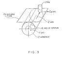
- FIG. 9 illustrates the cylindrical interpolation system, wherein a cylindrical surface is developed as an assumed plane 2a and an assumed orthogonal coordinate system is established based on the Z axis and an assumed linear axis Cy.
- This coordinate system is identical to a usual plane coordinate system, and a path of a tool 1 with reference to the orthogonal coordinate system is derived by a program. Since the shape to be machined is programmed with reference to a cylindrical coordinate system, it is converted into the assumed orthogonal coordinate system.
- the amount of movement of the Cy axis is converted back (from the orthogonal coordinate system to the cylindrical coordinate system) into an amount of rotation of the axis of rotation (C axis) 6 of a workpiece 2, to thereby control the C axis.
- Such a cylindrical interpolation system permits an easy preparation of a program for a complicated groove cutting.
- FIG. 10 shows the relationship between a tool and a workpiece during groove cutting according to a prior art cylindrical interpolation, in which a tool axis 1a is controlled so that it is at right angles to the cylindrical surface of the workpiece 2, and therefore, the tool cutting surface 5 and a line 3 perpendicular to the cylindrical surface of the workpiece 2 form a constant angle therebetween.
- a hatched portion 4 is cut unnecessarily, and thus a desired machining cannot be carried out.
- This invention was created in view of the above circumstances, and an object thereof is to provide a cylindrical interpolation system for correcting a tool position in accordance with a tool contact vector which is a vector from the center of a tool to a cutting point (point of contact) of the tool, such that the tool cutting surface is always at a right angle to the cylindrical surface.
- this invention provides a cylindrical interpolation system for machining the cylindrical surface of a cylindrical workpiece by means of a tool (1), the axis of the workpiece defining a rotational axis (C), the system comprising:
- the tool radius correcting means obtains a tool center path by calculating a tool radius offset vector with respect to a machining shape specified by the assumed orthogonal coordinate system, and the interpolating means interpolates the tool center path and outputs a first interpolation pulse related to the assumed linear axis and a second interpolation pulse related to the cylindrical axis.
- the pulse converting means converts the first interpolation pulse into a third pulse for rotating the rotary axis.
- the correction component calculating means obtains a correction component of the tool contact vector in the direction of the assumed linear axis, and the correction component interpolating means shifts the tool position by the correction component, and at the same time, rotates the workpiece.
- the tool cutting surface is controlled such that it is always located immediately above the axis of rotation of the workpiece, and thus the side of the surface being machined is at a right angle to the cylindrical surface of the workpiece.
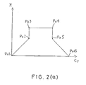
- FIG. 2(a) and FIG. 2(b) illustrate the concept of tool position correction adopted in a cylindrical interpolation system according to this invention, wherein FIG. 2(a) shows a development of a machining path onto a virtual or assumed plane, the machining path starting at a point Pa1, passing points Pa2, Pa3, Pa4 and Pa5, and ending at a point Pa6.
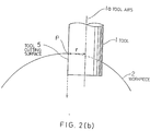
- FIG. 2(b) illustrates a tool position correction effected while the machining is executed along a straight section Pa2-Pa3 shown in FIG. 2(a).
- a tool axis 1a To bring a tool cutting surface 5 of a tool 1 to a position coinciding with a line perpendicular to the cylindrical surface of a workpiece 2, a tool axis 1a must be moved by a distance corresponding to a tool radius r such that the tool cutting surface 5 has a point P immediately above the axis of rotation of the workpiece 2. If, however, the tool 1 alone is moved, the relationship between the workpiece and the tool changes, and therefore, it is not advisable to merely move the tool alone.
- FIG. 3 and FIG. 4 illustrate the principle of this invention.
- the point P on the tool cutting surface is on a line 7 extending immediately above the axis of rotation 6 of the workpiece 2. Accordingly, when a point Q is to be contained in the tool cutting surface it must be moved onto the line 7, but if the tool is merely moved in a Y-axis direction, the relationship of the relative positioning between the assumed plane 2a developing the cylindrical surface of the workpiece 2 and the tool 1 changes. Therefore, to avoid this, while the tool 1 is moved in the Y-axis direction, the workpiece 2 is simultaneously rotated by an angle ⁇ about the axis of rotation 6.
- FIG. 3 illustrates the principle of this invention.
- the tool contact vector is rotated when a tool radius offset vector is varied.
- the tool radius offset vector and the tool contact vector have the same magnitude but opposite directions.
- the tool radius offset vector changes in individual blocks, each block defining a tool pass, and thus the rotation of the tool contact vector may be processed in individual blocks.
- the tool radius offset vector changes in accordance with pulse distribution, and therefore, the tool contact vector varies in accordance therewith. Accordingly, the tool 1 must be moved in the Y-axis direction simultaneously with the circular interpolation, while the workpiece 2 is rotated.
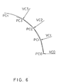
- FIG. 6 shows a change of the tool contact vector during a circular interpolation. It is assumed that the current tool contact point is at a point PC0 and the tool contact vector is VC0. If the tool contact point is to be shifted next to a point PC1 by a circular interpolation (an interpolation by a linear approximation), the tool contact vector changes from VC0 to VC1, and accordingly, the tool 1 must be moved in the Y-axis direction by a distance corresponding to a Cy-axis component of the difference between these tool contact vectors, and the workpiece 2 must be rotated over an angle corresponding to the Cy-axis component. A similar process may be effected when the tool contact point is shifted in the sequence of PC2, PC3 and PCn.
- the tool contact vector is varied at each circular interpolation in such a manner that the tool 1 is moved in the Y-axis direction, and simultaneously, pulses equivalent to an angle corresponding to the Y-axis movement of the workpiece 2 are added to C-axis interpolation pulses.
- FIG. 8 shows the hardware of a numerical control device (CNC) for carrying out this invention.
- reference numeral 10 denotes a numerical control device (CNC), and a processor 11, which globally controls the numerical control device (CNC) 10, reads out a system program stored in a ROM 12 through a bus 21, and controls the entire operation of the numerical control device (CNC) 10 in accordance with the system program.
- a RAM 13 temporarily stores calculation data and display data, etc., and comprises an SRAM, for example.
- a CMOS 14 stores tool correction values, pitch error correction values, a machining program, parameters and the like, and comprises a nonvolatile memory backed up by a not shown battery so that the data therein is retained even after the power supply to the numerical control device (CNC) 10 is cut off.
- CNC numerical control device
- a graphic control circuit 18 converts digital data representing current positions of the individual axes, alarms, parameters, and image data, etc. into image signals and outputs the converted data.
- the image signals are supplied to a display device 26 of a CRT/MDI unit 25 and displayed thereby.
- An interface 19 transfers data from a keyboard 27 of the CRT/MDI unit 25 to the processor 11.
- An interface 20 is connected to a manual pulse generator 32 for receiving pulses therefrom.
- the manual pulse generator 32 is incorporated in the machine operator panel, and is used to manually precisely position a machine operating part.
- Axis control circuits 41 to 44 receive move commands for the respective axes from the processor 11 and output commands to servo amplifiers 51 to 54, respectively, and upon receiving the move commands, the servo amplifiers 51 to 54 drive servomotors 61 to 64 associated with the respective axes.
- a position detection pulse coder is built into each of the servomotors 61 to 64, and a position signal therefrom is fed back in the form of a pulse train.
- a linear scale may be used as the position detector.
- the pulse train is subjected to an F/V (frequency-to-velocity) conversion to generate a velocity signal.
- F/V frequency-to-velocity
- the servomotors 61 to 64 are associated respectively with the X, Y, Z and C axes.
- a spindle control circuit 71 receives a spindle rotation command and a spindle orientation command, etc., and outputs a spindle velocity signal to a spindle amplifier 72, and upon receiving the spindle velocity signal, the spindle amplifier 72 rotates a spindle motor 73 at the specified speed.
- the spindle is positioned at a predetermined position in accordance with the orientation command.
- FIG. 1 is a block diagram illustrating various means incorporated in the cylindrical interpolation system according to this invention. These means are operated by the processor 11 in accordance with the system program stored in the ROM 12.
- commands in the machining program 101 are decoded by the decoding means 102, and the C-axis command is converted by the coordinate conversion means 103 into values with reference to the assumed linear axis Cy. Then, based on these commands, a tool radius correcting means 104 obtains a tool center path in accordance with a program path with respect to the Z axis and the assumed linear axis Cy, and the tool radius r, i.e., the tool radius correcting means 104 outputs a command value representing the center path of the tool 1.
- the tool radius correcting means 104 outputs a move command Z for the tool 1 and a command Cy with respect to the assumed linear axis, to the interpolating means 107, and further supplies a tool radius offset vector to the block-start correction component calculating means 105, and a tool radius and an offset direction to the synchronous correction component calculating means 109.
- the interpolating means 107 interpolates the commands Z and Cy, and outputs an interpolation pulse PCyi related to the assumed linear axis, and an interpolation pulse PZi related to the Z axis, to the pulse converting means 108.
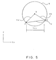
- the block-start correction component calculating means 105 obtains a correction component Vcy of the tool contact vector in the direction of the assumed linear axis, as shown in FIG. 5, from the tool radius offset vector.
- the tool contact vector differs from the tool radius offset vector only in direction, and thus the correction component can be derived by obtaining a tool contact vector from the tool radius offset vector and obtaining an assumed linear axis component of its vector of rotation, as shown in FIG. 5.
- the correction component Vcy is interpolated by the block-start correction component interpolating means 106, and is output therefrom as a correction pulse RYj for the Y axis and a correction pulse RCj for the rotary axis.
- the sum of the correction pulses RYj is equivalent to the distance between the points P and Q on the cylindrical surface 2a in the Y-axis direction, as shown in FIG. 3.
- the C axis is rotated by ⁇ , as shown in FIG. 3, in accordance with the correction pulse RCj.
- the block-start correction component calculating means 105 calculates a correction component.
- the interpolation by the block-start correction component interpolating means 106 is effected before an interpolation for the movement of the tool 1 from P2 to P3.
- the synchronous correction component calculating means 109 calculates a correction component when the tool contact vector changes at each interpolation of the interpolating means 107, e.g., in a circular interpolation shown in FIG. 6, involute interpolation, or the like. Namely, when the tool contact vector changes from VCO to VC1, as shown in FIG. 6, an assumed linear axis component ⁇ Vcy corresponding to the change of the tool contact vector is obtained and supplied to the synchronous correction component interpolating means 110.
- the synchronous correction component interpolating means 110 interpolates the correction component ⁇ Vcy each time the interpolating means 107 carries out an interpolation, and outputs a correction pulse RCi for the C axis and a correction pulse RYi for the Y axis. These correction pulses RCi and RYi are output from the interpolating means 107 synchronously with the interpolation pulses PCi and PZi.
- the correction pulses RYj and RYi for the Y axis are added at an adder 111, and the result is supplied to the axis control circuit 42 as an output pulse for the Y axis. In this case, the correction pulses RYj and RYi are not output at the same time.
- the correction pulse RCj, interpolation pulse PCi and correction pulse RCi for the C axis are added at an adder 112, and the result is supplied to the axis control circuit 44.
- the correction pulse RCi and the interpolation pulse PCi are superimposed when output.
- the interpolation pulse PZi for the Z axis is supplied to the axis control circuit 43.
- the C axis is rotated and the Y axis is moved in accordance with an assumed linear axis component corresponding to the change of the tool contact vector, whereby the tool cutting surface is located immediately above the axis of rotation of the workpiece and the side surface being machined is brought to a position perpendicular to the cylindrical surface of the workpiece.
- the Z, C and Y axes represent a cylindrical axis, a rotary axis, and an axis perpendicular to the cylindrical axis, respectively, but these axes are named only for explanation purposes, and may be modified depending on the arrangement of the machines.
- the rotary axis command in the machining program is set in terms of angles, but command values which have been converted with reference to the assumed linear axis by a programming system may be alternatively used. In this case, the coordinate conversion means shown in FIG. 1 is not necessary.
- the Y axis is moved by an assumed linear axis component corresponding to the change of the tool contact vector, and at the same time, the rotary axis is rotated by a cylindrical interpolation to carry out a tool position correction, whereby the tool cutting surface is always located immediately above the axis of rotation of the workpiece and the side surface being machined is at a right angle to the cylindrical surface of the workpiece.
Abstract
Description
- This invention relates to a cylindrical interpolation for machining a cylindrical surface of a cylindrical workpiece by a numerical control device, and more particularly, to a cylindrical interpolation system in which a tool cutting surface is always located at right angles to the cylindrical surface.
- When carrying out a complicated groove cutting in a cylindrical workpiece, using an end mill at a machining center or the like, the machining operation is effected by controlling a cylindrical axis (Z) and a rotary axis (C), and for such a machining, a cylindrical interpolation system is widely used to facilitate the preparation of a machining program.
- FIG. 9 illustrates the cylindrical interpolation system, wherein a cylindrical surface is developed as an assumed
plane 2a and an assumed orthogonal coordinate system is established based on the Z axis and an assumed linear axis Cy. This coordinate system is identical to a usual plane coordinate system, and a path of atool 1 with reference to the orthogonal coordinate system is derived by a program. Since the shape to be machined is programmed with reference to a cylindrical coordinate system, it is converted into the assumed orthogonal coordinate system. After the interpolation for the Z and Cy axes is effected with reference to the orthogonal coordinate system, the amount of movement of the Cy axis is converted back (from the orthogonal coordinate system to the cylindrical coordinate system) into an amount of rotation of the axis of rotation (C axis) 6 of aworkpiece 2, to thereby control the C axis. Such a cylindrical interpolation system permits an easy preparation of a program for a complicated groove cutting. - Nevertheless, in the prior art cylindrical interpolation system, the tool cutting surface is not always at right angles to the cylindrical surface. FIG. 10 shows the relationship between a tool and a workpiece during groove cutting according to a prior art cylindrical interpolation, in which a tool axis 1a is controlled so that it is at right angles to the cylindrical surface of the
workpiece 2, and therefore, thetool cutting surface 5 and aline 3 perpendicular to the cylindrical surface of theworkpiece 2 form a constant angle therebetween. As a result, a hatchedportion 4 is cut unnecessarily, and thus a desired machining cannot be carried out. - This invention was created in view of the above circumstances, and an object thereof is to provide a cylindrical interpolation system for correcting a tool position in accordance with a tool contact vector which is a vector from the center of a tool to a cutting point (point of contact) of the tool, such that the tool cutting surface is always at a right angle to the cylindrical surface.
- To achieve the above object, this invention provides a cylindrical interpolation system for machining the cylindrical surface of a cylindrical workpiece by means of a tool (1), the axis of the workpiece defining a rotational axis (C), the system comprising:
- tool radius correcting means for obtaining a tool center path by calculating a tool radius offset vector in virtual plane defined by a cylindrical axis and virtual linear axis obtained through a development of the workpiece surfaces , said tool center path being defined such that the tool cutting surface is located immediately above the rotational axis of the workpiece;
- interpolating means for interpolating the tool center path and outputting a first interpolation pulse related to the virtual linear axis and a second interpolation pulse related to the cylindrical axis;
- pulse converting means for converting the first interpolation pulse into a third interpolation pulse related to said rotational axis;
- correction component calculating means for calculating a correction component of a tool contact vector in a direction of the virtual linear axis from the tool radius offset vector;
- correction component interpolating means for interpolating the correction component and outputting a first correction pulse related to said rotational axis and a second correction pulse related to the virtual axis ; and
- an adder for adding the third interpolation pulse and the first correction pulse and providing an output pulse defining rotation of the workpiece around the rotational axis to bring the workpiece in to working position with the tool and thereby compensating for the movement of the tool.
- The tool radius correcting means obtains a tool center path by calculating a tool radius offset vector with respect to a machining shape specified by the assumed orthogonal coordinate system, and the interpolating means interpolates the tool center path and outputs a first interpolation pulse related to the assumed linear axis and a second interpolation pulse related to the cylindrical axis. To carry out a reverse conversion from the assumed orthogonal coordinate system to the cylindrical coordinate system, the pulse converting means converts the first interpolation pulse into a third pulse for rotating the rotary axis.
- The correction component calculating means obtains a correction component of the tool contact vector in the direction of the assumed linear axis, and the correction component interpolating means shifts the tool position by the correction component, and at the same time, rotates the workpiece.
- As a result, the tool cutting surface is controlled such that it is always located immediately above the axis of rotation of the workpiece, and thus the side of the surface being machined is at a right angle to the cylindrical surface of the workpiece.
- In the drawings:-
- FIG. 1 is a block diagram illustrating various means composing a cylindrical interpolation system according to this invention;
- FIG. 2(a) and FIG. 2(b) are diagrams illustrating the concept of correcting a tool position according to the cylindrical interpolation system of this invention;
- FIG. 3 and FIG. 4 are diagrams illustrating the principle of this invention;
- FIG. 5 is a plan view illustrating the relationship between a tool contact vector and a tool position correction value in a Y-axis direction;
- FIG. 6 is a diagram illustrating a change of the tool contact vector during a circular interpolation;
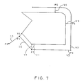
- FIG. 7 is a diagram illustrating the relationship between a tool center path and the tool contact vector;
- FIG. 8 is a block diagram of hardware of a numerical control device (CNC) for carrying out this invention;
- FIG. 9 is a diagram illustrating a cylindrical interpolation system; and
- FIG. 10 is a diagram illustrating the relationship between a tool and a workpiece during a groove cutting by a prior art cylindrical interpolation system.
- An embodiment of this invention will be described with reference to the drawings.
- FIG. 2(a) and FIG. 2(b) illustrate the concept of tool position correction adopted in a cylindrical interpolation system according to this invention, wherein FIG. 2(a) shows a development of a machining path onto a virtual or assumed plane, the machining path starting at a point Pa1, passing points Pa2, Pa3, Pa4 and Pa5, and ending at a point Pa6.
- FIG. 2(b) illustrates a tool position correction effected while the machining is executed along a straight section Pa2-Pa3 shown in FIG. 2(a). To bring a
tool cutting surface 5 of atool 1 to a position coinciding with a line perpendicular to the cylindrical surface of aworkpiece 2, a tool axis 1a must be moved by a distance corresponding to a tool radius r such that thetool cutting surface 5 has a point P immediately above the axis of rotation of theworkpiece 2. If, however, thetool 1 alone is moved, the relationship between the workpiece and the tool changes, and therefore, it is not advisable to merely move the tool alone. - FIG. 3 and FIG. 4 illustrate the principle of this invention. In FIG. 3, the point P on the tool cutting surface is on a
line 7 extending immediately above the axis ofrotation 6 of theworkpiece 2. Accordingly, when a point Q is to be contained in the tool cutting surface it must be moved onto theline 7, but if the tool is merely moved in a Y-axis direction, the relationship of the relative positioning between the assumedplane 2a developing the cylindrical surface of theworkpiece 2 and thetool 1 changes. Therefore, to avoid this, while thetool 1 is moved in the Y-axis direction, theworkpiece 2 is simultaneously rotated by an angle θ about the axis ofrotation 6. FIG. 4 shows a state in which thetool 1 has been moved in the Y-axis direction, and at the same time, theworkpiece 2 has been rotated by the angle θ. Namely, aline 8, not theline 7, is now located immediately above the axis ofrotation 6 of theworkpiece 2. The angle θ is derived by the following equation:
tool 1 in the Y-axis direction, and R represents the radius of theworkpiece 2. - FIG. 5 is a plan view showing the relationship between the tool and a tool contact vector. As shown in FIG. 3, the tool contact point is first located at P, and then shifted to the point Q for the subsequent machining operation. Namely, first the tool contact vector is Va, and is then Vb, based on the center O of the
tool 1, i.e., the tool contact vector changes from Va to Vb. Accordingly, it follows that, if a difference Vcy between the tool contact vectors Va and Vb in the direction of the assumed linear axis Cy is obtained, and thetool 1 is moved by Vcy in the Y-axis direction while theworkpiece 2 is rotated over the corresponding angle θ, the tool contact point Q can be shifted to a position immediately above the axis ofrotation 6, and at the same time, the relationship of relative positioning between the assumedplane 2a of theworkpiece 2 and thetool 1 is maintained. - Generally, the tool contact vector is rotated when a tool radius offset vector is varied. Namely, the tool radius offset vector and the tool contact vector have the same magnitude but opposite directions. Accordingly, in a linear interpolation, the tool radius offset vector changes in individual blocks, each block defining a tool pass, and thus the rotation of the tool contact vector may be processed in individual blocks. In a circular interpolation, the tool radius offset vector changes in accordance with pulse distribution, and therefore, the tool contact vector varies in accordance therewith. Accordingly, the
tool 1 must be moved in the Y-axis direction simultaneously with the circular interpolation, while theworkpiece 2 is rotated. - FIG. 6 shows a change of the tool contact vector during a circular interpolation. It is assumed that the current tool contact point is at a point PC0 and the tool contact vector is VC0. If the tool contact point is to be shifted next to a point PC1 by a circular interpolation (an interpolation by a linear approximation), the tool contact vector changes from VC0 to VC1, and accordingly, the
tool 1 must be moved in the Y-axis direction by a distance corresponding to a Cy-axis component of the difference between these tool contact vectors, and theworkpiece 2 must be rotated over an angle corresponding to the Cy-axis component. A similar process may be effected when the tool contact point is shifted in the sequence of PC2, PC3 and PCn. - FIG. 7 shows the relationship between the tool center path and the tool contact vector. The tool center is successively moved from a point Ps to points P1, P2, P3, P4 and P5. The tool center path is indicated by 1C. At the point P1, the tool contact vector is V1, and is changed to V2 as the tool center is shifted to the point P2. For the point P3, the vector is changed from V2 to V3. To make each new tool contact point coincide with the axis of rotation of the workpiece, the
tool 1 is moved in the Y-axis direction by a Y-axis component of the difference between the previous and the next tool contact vectors, and simultaneously, theworkpiece 2 is rotated by an amount corresponding to the amount of movement in the Y-axis direction. - For an arcuate section from the point P4 to P5, the tool contact vector is varied at each circular interpolation in such a manner that the
tool 1 is moved in the Y-axis direction, and simultaneously, pulses equivalent to an angle corresponding to the Y-axis movement of theworkpiece 2 are added to C-axis interpolation pulses. - FIG. 8 shows the hardware of a numerical control device (CNC) for carrying out this invention. In the figure,
reference numeral 10 denotes a numerical control device (CNC), and a processor 11, which globally controls the numerical control device (CNC) 10, reads out a system program stored in aROM 12 through abus 21, and controls the entire operation of the numerical control device (CNC) 10 in accordance with the system program. ARAM 13 temporarily stores calculation data and display data, etc., and comprises an SRAM, for example. ACMOS 14 stores tool correction values, pitch error correction values, a machining program, parameters and the like, and comprises a nonvolatile memory backed up by a not shown battery so that the data therein is retained even after the power supply to the numerical control device (CNC) 10 is cut off. - An
interface 15 for external devices is connected to anexternal device 31, such as a paper tape reader, paper tape puncher, paper tape reader/puncher, etc. The paper tape reader is used to read a machining program, and the paper tape puncher is used for outputting a machining program edited in the numerical control device (CNC) 10. - A PMC (programmable machine controller) 16, which is built into the
CNC 10, controls the machine in accordance with a sequence program prepared in a ladder format. Namely, the PMC converts M, S and T functions, specified by the machining program, into signals required on the machine side in accordance with the sequence program, and outputs the converted signals to the machine side through an I/O unit 17. The output signals drive magnets, etc., on the machine side, to thereby actuate hydraulic valves, pneumatic valves, and electric actuators, etc. Further, the PMC processes signals from limit switches of the machine side and from switches on a machine operator panel, and supplies the processed signals to the processor 11. - A
graphic control circuit 18 converts digital data representing current positions of the individual axes, alarms, parameters, and image data, etc. into image signals and outputs the converted data. The image signals are supplied to adisplay device 26 of a CRT/MDI unit 25 and displayed thereby. Aninterface 19 transfers data from a keyboard 27 of the CRT/MDI unit 25 to the processor 11. - An
interface 20 is connected to amanual pulse generator 32 for receiving pulses therefrom. Themanual pulse generator 32 is incorporated in the machine operator panel, and is used to manually precisely position a machine operating part. -
Axis control circuits 41 to 44 receive move commands for the respective axes from the processor 11 and output commands to servo amplifiers 51 to 54, respectively, and upon receiving the move commands, the servo amplifiers 51 to 54drive servomotors 61 to 64 associated with the respective axes. A position detection pulse coder is built into each of theservomotors 61 to 64, and a position signal therefrom is fed back in the form of a pulse train. Alternatively, a linear scale may be used as the position detector. The pulse train is subjected to an F/V (frequency-to-velocity) conversion to generate a velocity signal. In the figure, a feedback line for the position signal and a velocity feedback are omitted. - The
servomotors 61 to 64 are associated respectively with the X, Y, Z and C axes. - A
spindle control circuit 71 receives a spindle rotation command and a spindle orientation command, etc., and outputs a spindle velocity signal to aspindle amplifier 72, and upon receiving the spindle velocity signal, thespindle amplifier 72 rotates aspindle motor 73 at the specified speed. The spindle is positioned at a predetermined position in accordance with the orientation command. - A
position coder 82 is coupled to thespindle motor 73 by gears or a belt, and thus theposition coder 82 is rotated synchronously with thespindle motor 73, and a feedback pulse output therefrom is supplied to the processor 11 through aninterface 81, and read thereby. This feedback pulse is used to move the other axes synchronously with thespindle motor 73, for carrying out a machining such as thread cutting. - FIG. 1 is a block diagram illustrating various means incorporated in the cylindrical interpolation system according to this invention. These means are operated by the processor 11 in accordance with the system program stored in the
ROM 12. - Here it is assumed that a machining program 101 includes a Z-axis command and a C-axis command, and that the C-axis command is set in units of angles. A decoding means 102 decodes this command and determines that it is a cylindrical interpolation command, and then a coordinate conversion means 103 converts the C-axis rotation command into an assumed linear axis Cy on an assumed plane. Namely, the coordinates specified in angles of rotation are converted into a distance on the cylindrical surface of the
workpiece 2 corresponding to the rotation angle. - Namely, commands in the machining program 101 are decoded by the decoding means 102, and the C-axis command is converted by the coordinate conversion means 103 into values with reference to the assumed linear axis Cy. Then, based on these commands, a tool radius correcting means 104 obtains a tool center path in accordance with a program path with respect to the Z axis and the assumed linear axis Cy, and the tool radius r, i.e., the tool radius correcting means 104 outputs a command value representing the center path of the
tool 1. - Namely, the tool radius correcting means 104 outputs a move command Z for the
tool 1 and a command Cy with respect to the assumed linear axis, to the interpolating means 107, and further supplies a tool radius offset vector to the block-start correction component calculating means 105, and a tool radius and an offset direction to the synchronous correction component calculating means 109. - The interpolating means 107 interpolates the commands Z and Cy, and outputs an interpolation pulse PCyi related to the assumed linear axis, and an interpolation pulse PZi related to the Z axis, to the pulse converting means 108. The pulse converting means 108 converts the interpolation pulse PCyi into an interpolation pulse PCi related to the rotary axis (C axis), as indicated by the following equation (2):

workpiece 2. - The block-start correction component calculating means 105 obtains a correction component Vcy of the tool contact vector in the direction of the assumed linear axis, as shown in FIG. 5, from the tool radius offset vector. The tool contact vector differs from the tool radius offset vector only in direction, and thus the correction component can be derived by obtaining a tool contact vector from the tool radius offset vector and obtaining an assumed linear axis component of its vector of rotation, as shown in FIG. 5.
- The correction component Vcy is interpolated by the block-start correction component interpolating means 106, and is output therefrom as a correction pulse RYj for the Y axis and a correction pulse RCj for the rotary axis. The sum of the correction pulses RYj is equivalent to the distance between the points P and Q on the
cylindrical surface 2a in the Y-axis direction, as shown in FIG. 3. The C axis is rotated by θ, as shown in FIG. 3, in accordance with the correction pulse RCj. - When the tool contact vector is rotated between successive blocks, e.g., the center of the
tool 1 is at the point P2 in FIG. 7, the block-start correction component calculating means 105 calculates a correction component. The interpolation by the block-start correction component interpolating means 106 is effected before an interpolation for the movement of thetool 1 from P2 to P3. - The synchronous correction component calculating means 109 calculates a correction component when the tool contact vector changes at each interpolation of the interpolating means 107, e.g., in a circular interpolation shown in FIG. 6, involute interpolation, or the like. Namely, when the tool contact vector changes from VCO to VC1, as shown in FIG. 6, an assumed linear axis component ΔVcy corresponding to the change of the tool contact vector is obtained and supplied to the synchronous correction component interpolating means 110. The synchronous correction component interpolating means 110 interpolates the correction component ΔVcy each time the interpolating means 107 carries out an interpolation, and outputs a correction pulse RCi for the C axis and a correction pulse RYi for the Y axis. These correction pulses RCi and RYi are output from the interpolating means 107 synchronously with the interpolation pulses PCi and PZi.
- The correction pulses RYj and RYi for the Y axis are added at an adder 111, and the result is supplied to the
axis control circuit 42 as an output pulse for the Y axis. In this case, the correction pulses RYj and RYi are not output at the same time. - The correction pulse RCj, interpolation pulse PCi and correction pulse RCi for the C axis are added at an adder 112, and the result is supplied to the axis control circuit 44. The correction pulse RCi and the interpolation pulse PCi are superimposed when output.
- The interpolation pulse PZi for the Z axis is supplied to the axis control circuit 43.
- As described above, the C axis is rotated and the Y axis is moved in accordance with an assumed linear axis component corresponding to the change of the tool contact vector, whereby the tool cutting surface is located immediately above the axis of rotation of the workpiece and the side surface being machined is brought to a position perpendicular to the cylindrical surface of the workpiece.
- In the above description, the Z, C and Y axes represent a cylindrical axis, a rotary axis, and an axis perpendicular to the cylindrical axis, respectively, but these axes are named only for explanation purposes, and may be modified depending on the arrangement of the machines.
- Further, in the above description, the rotary axis command in the machining program is set in terms of angles, but command values which have been converted with reference to the assumed linear axis by a programming system may be alternatively used. In this case, the coordinate conversion means shown in FIG. 1 is not necessary.
- As described above, according to this invention, the Y axis is moved by an assumed linear axis component corresponding to the change of the tool contact vector, and at the same time, the rotary axis is rotated by a cylindrical interpolation to carry out a tool position correction, whereby the tool cutting surface is always located immediately above the axis of rotation of the workpiece and the side surface being machined is at a right angle to the cylindrical surface of the workpiece.
Claims (6)
- A cylindrical interpolation system for machining the cylindrical surface of a cylindrical workpiece (2) by means of a tool (1), the axis of the workpiece defining a rotational axis (C), the system comprising:tool radius correcting means (104) for obtaining a tool center path by calculating a tool radius offset vector in a virtual plane defined by a cylindrical axis (Z) and a virtual linear axis (Cy) obtained through a development of the workpiece surface, said tool center path being defined such that the tool cutting surface is located immediately above the rotational axis of the workpiece;interpolating means (107) for interpolating the tool center path and outputting a first interpolation pulse (PCyi) related to the virtual linear axis and a second interpolation pulse (PZi) related to the cylindrical axis;pulse converting means (108) for converting the first interpolation pulse into a third interpolation pulse (PCi) related to said rotational axis (C);correction component calculating means (105,109) for calculating a correction component of a tool contact vector in a direction of the virtual linear axis from the tool radius offset vector;correction component interpolating means (106, 110) for interpolating the correction component (VCy, ΔVCy) and outputting a first correction pulse (RCj, RCi) related to said rotational axis and a second correction pulse (RYj, RYi) related to the virtual linear ; andan adder (112) for adding the third interpolation pulse (PCi) and the first correction pulse (RCi) and providing an output pulse defining rotation of the workpiece around the rotational axis (C) to bring the workpiece into working position with the tool and thereby compensating for the movement of the tool.
- A cylindrical interpolation system according to claim 1, wherein said correction component calculating means (105,109) comprises block-start correction component calculating means (105) for obtaining a correction component (VCy) between the tool contact vectors of successive blocks, each block defining a tool pass, and synchronous correction component calculating means (109) for calculating a correction component (Δ VCy) for each interpolation step.
- A cylindrical interpolation system according to claim 1, wherein said correction component interpolating means (106,110) comprises block-start correction component interpolating means (106) for interpolating a block-start correction component (RYj) before an interpolation by the interpolating means, and synchronous correction component interpolating means (110) for interpolating a synchronous correction component synchronously with each interpolation step by the interpolating means.
- A cylindrical interpolation system according to claim 1, wherein said cylindrical axis comprises a Z axis, the rotary axis comprises a C axis, and the axis perpendicular to the cylindrical axis comprises a Y axis.
- A cylindrical interpolation system according to claim 1, wherein an axis rotation command in a machining program (101) is set in terms of angles of rotation, and the system further comprises coordinate conversion means (103) for converting the axis rotation command into a linear command value related to the virtual linear axis (Cy) on the development of the workpiece surface.
- A cylindrical interpolation system according to claim 1, wherein an axis rotation command in a machining program (101) is set as an amount of movement along the virtual linear axis (Cy).
Applications Claiming Priority (3)
| Application Number | Priority Date | Filing Date | Title |
|---|---|---|---|
| JP2134836A JP2726735B2 (en) | 1990-05-24 | 1990-05-24 | Cylindrical interpolation method |
| JP134836/90 | 1990-05-24 | ||
| PCT/JP1991/000584 WO1991018335A1 (en) | 1990-05-24 | 1991-04-26 | Cylinder interpolation system |
Publications (3)
| Publication Number | Publication Date |
|---|---|
| EP0484539A1 EP0484539A1 (en) | 1992-05-13 |
| EP0484539A4 EP0484539A4 (en) | 1993-03-03 |
| EP0484539B1 true EP0484539B1 (en) | 1996-08-21 |
Family
ID=15137600
Family Applications (1)
| Application Number | Title | Priority Date | Filing Date |
|---|---|---|---|
| EP91908173A Expired - Lifetime EP0484539B1 (en) | 1990-05-24 | 1991-04-26 | Cylinder interpolation system |
Country Status (5)
| Country | Link |
|---|---|
| US (1) | US5282144A (en) |
| EP (1) | EP0484539B1 (en) |
| JP (1) | JP2726735B2 (en) |
| DE (1) | DE69121518T2 (en) |
| WO (1) | WO1991018335A1 (en) |
Families Citing this family (11)
| Publication number | Priority date | Publication date | Assignee | Title |
|---|---|---|---|---|
| JPH0736514A (en) * | 1993-07-20 | 1995-02-07 | Fanuc Ltd | Three-dimensional tool diameter correction system |
| JPH07164359A (en) * | 1993-12-10 | 1995-06-27 | Fanuc Ltd | Circular arc tracking method of robot |
| US5910199A (en) * | 1997-02-26 | 1999-06-08 | Vickers, Incorporated | Method and apparatus for fast threading pullout in a numerically controlled threading application |
| DE60035131T2 (en) * | 2000-09-20 | 2008-01-31 | Mitsubishi Denki K.K. | NUMERICAL CONTROL METHOD AND NUMERICAL CONTROL DEVICE |
| DE10208411B4 (en) * | 2002-02-27 | 2004-11-04 | Werkzeugmaschinenfabrik Zerbst Gmbh | Process for machining workpieces with straight surface recesses |
| DE10330828B4 (en) | 2003-07-08 | 2006-09-21 | Mtu Aero Engines Gmbh | Method and device for milling free-form surfaces |
| TW200920521A (en) | 2007-04-05 | 2009-05-16 | Toshiba Machine Co Ltd | Method and apparatus for machining surface of roll |
| CN101887250B (en) * | 2009-05-12 | 2012-05-30 | 鸿富锦精密工业(深圳)有限公司 | CNC (Computerized Numerical Control) machine tool control device |
| JP4837110B2 (en) | 2010-02-18 | 2011-12-14 | ファナック株式会社 | Numerical control device with tool path display function |
| JP5236026B2 (en) * | 2011-01-20 | 2013-07-17 | 三菱電機株式会社 | Numerical control method |
| JP6166300B2 (en) | 2015-04-13 | 2017-07-19 | ファナック株式会社 | Numerical control device that can check interference between tool and workpiece |
Family Cites Families (10)
| Publication number | Priority date | Publication date | Assignee | Title |
|---|---|---|---|---|
| US4598380A (en) * | 1984-08-13 | 1986-07-01 | Cincinnati Milacron Inc. | Method and apparatus for controlling manipulator and workpiece positioner |
| JPS6168606A (en) * | 1984-09-12 | 1986-04-09 | Mitsubishi Electric Corp | Numerical controller |
| JPS62163109A (en) * | 1986-01-14 | 1987-07-18 | Mitsubishi Electric Corp | Numerical controller |
| JPS6320601A (en) * | 1986-07-15 | 1988-01-28 | Mitsubishi Electric Corp | Numerical controller |
| JPS63152206A (en) * | 1986-12-17 | 1988-06-24 | Hitachi Ltd | Amplifier circuit |
| JPS63155206A (en) * | 1986-12-18 | 1988-06-28 | Fanuc Ltd | Numerical control system |
| JPS6435605A (en) * | 1987-07-30 | 1989-02-06 | Fanuc Ltd | Numerical controller |
| JPH01152508A (en) * | 1987-12-10 | 1989-06-15 | Fanuc Ltd | Cnc control system |
| JP3004651B2 (en) * | 1988-01-08 | 2000-01-31 | ファナック株式会社 | Numerical control unit |
| JP2801064B2 (en) * | 1990-03-20 | 1998-09-21 | 東芝機械株式会社 | NC equipment |
-
1990
- 1990-05-24 JP JP2134836A patent/JP2726735B2/en not_active Expired - Fee Related
-
1991
- 1991-04-26 DE DE69121518T patent/DE69121518T2/en not_active Expired - Fee Related
- 1991-04-26 EP EP91908173A patent/EP0484539B1/en not_active Expired - Lifetime
- 1991-04-26 WO PCT/JP1991/000584 patent/WO1991018335A1/en active IP Right Grant
- 1991-05-26 US US07/820,665 patent/US5282144A/en not_active Expired - Lifetime
Also Published As
| Publication number | Publication date |
|---|---|
| JP2726735B2 (en) | 1998-03-11 |
| EP0484539A4 (en) | 1993-03-03 |
| WO1991018335A1 (en) | 1991-11-28 |
| JPH0433013A (en) | 1992-02-04 |
| EP0484539A1 (en) | 1992-05-13 |
| DE69121518T2 (en) | 1997-01-02 |
| DE69121518D1 (en) | 1996-09-26 |
| US5282144A (en) | 1994-01-25 |
Similar Documents
| Publication | Publication Date | Title |
|---|---|---|
| US8868228B2 (en) | Numerical controller having speed control function for multi-axis machining device | |
| EP0484539B1 (en) | Cylinder interpolation system | |
| US5563484A (en) | Three-dimensional cutter compensation system | |
| JPH11149306A (en) | Controller for finishing machine | |
| US6539275B1 (en) | Machine controller and process with two-step interpolation | |
| US10137529B2 (en) | Numerical controller capable of machining condition control based on posture | |
| JP2005182437A (en) | Numerical control device and numerical control method | |
| EP0356522A1 (en) | Involute interpolating method | |
| JPWO2004102290A1 (en) | Numerical controller | |
| US5545959A (en) | Speed control method for a numerical control apparatus | |
| US10073432B2 (en) | Numerical controller having tool tip point control function | |
| US5181178A (en) | Spindle control command method | |
| JPH06285701A (en) | Nc lathe turning device | |
| US5239159A (en) | Nozzle movement system for laser machining equipment | |
| JPH01177617A (en) | Involute interpolation system | |
| JPH0887312A (en) | Cylinder interpolation system | |
| JPH11165220A (en) | Control device for wire electric discharge machining with offset correction function | |
| JPH05100723A (en) | Tool length correcting system for machine tool | |
| JP2796335B2 (en) | Numerical control unit | |
| JPH06304845A (en) | Numerical control device | |
| JPH0659719A (en) | Numerical controller | |
| JPH0474205A (en) | Correction system for tool diameter | |
| JPH07334223A (en) | Tool spindle attitude control system | |
| JPH06312341A (en) | Numeral control device | |
| JPH03109606A (en) | Tool correction system |
Legal Events
| Date | Code | Title | Description |
|---|---|---|---|
| PUAI | Public reference made under article 153(3) epc to a published international application that has entered the european phase |
Free format text: ORIGINAL CODE: 0009012 |
|
| 17P | Request for examination filed |
Effective date: 19920220 |
|
| AK | Designated contracting states |
Kind code of ref document: A1 Designated state(s): CH DE IT LI |
|
| A4 | Supplementary search report drawn up and despatched |
Effective date: 19930111 |
|
| AK | Designated contracting states |
Kind code of ref document: A4 Designated state(s): CH DE IT LI |
|
| 17Q | First examination report despatched |
Effective date: 19941227 |
|
| GRAH | Despatch of communication of intention to grant a patent |
Free format text: ORIGINAL CODE: EPIDOS IGRA |
|
| GRAH | Despatch of communication of intention to grant a patent |
Free format text: ORIGINAL CODE: EPIDOS IGRA |
|
| GRAA | (expected) grant |
Free format text: ORIGINAL CODE: 0009210 |
|
| AK | Designated contracting states |
Kind code of ref document: B1 Designated state(s): CH DE IT LI |
|
| PG25 | Lapsed in a contracting state [announced via postgrant information from national office to epo] |
Ref country code: IT Free format text: LAPSE BECAUSE OF FAILURE TO SUBMIT A TRANSLATION OF THE DESCRIPTION OR TO PAY THE FEE WITHIN THE PRESCRIBED TIME-LIMIT;WARNING: LAPSES OF ITALIAN PATENTS WITH EFFECTIVE DATE BEFORE 2007 MAY HAVE OCCURRED AT ANY TIME BEFORE 2007. THE CORRECT EFFECTIVE DATE MAY BE DIFFERENT FROM THE ONE RECORDED. Effective date: 19960821 Ref country code: CH Effective date: 19960821 Ref country code: LI Effective date: 19960821 |
|
| REF | Corresponds to: |
Ref document number: 69121518 Country of ref document: DE Date of ref document: 19960926 |
|
| REG | Reference to a national code |
Ref country code: CH Ref legal event code: PL |
|
| PLBE | No opposition filed within time limit |
Free format text: ORIGINAL CODE: 0009261 |
|
| STAA | Information on the status of an ep patent application or granted ep patent |
Free format text: STATUS: NO OPPOSITION FILED WITHIN TIME LIMIT |
|
| 26N | No opposition filed | ||
| PGFP | Annual fee paid to national office [announced via postgrant information from national office to epo] |
Ref country code: DE Payment date: 20080502 Year of fee payment: 18 |
|
| PG25 | Lapsed in a contracting state [announced via postgrant information from national office to epo] |
Ref country code: DE Free format text: LAPSE BECAUSE OF NON-PAYMENT OF DUE FEES Effective date: 20091103 |