EP0909852A1 - Stopfaggregat - Google Patents
Stopfaggregat Download PDFInfo
- Publication number
- EP0909852A1 EP0909852A1 EP98890251A EP98890251A EP0909852A1 EP 0909852 A1 EP0909852 A1 EP 0909852A1 EP 98890251 A EP98890251 A EP 98890251A EP 98890251 A EP98890251 A EP 98890251A EP 0909852 A1 EP0909852 A1 EP 0909852A1
- Authority
- EP
- European Patent Office
- Prior art keywords
- tamping
- drive
- additional
- swivel drive
- pick
- Prior art date
- Legal status (The legal status is an assumption and is not a legal conclusion. Google has not performed a legal analysis and makes no representation as to the accuracy of the status listed.)
- Granted
Links
Images
Classifications
-
- E—FIXED CONSTRUCTIONS
- E01—CONSTRUCTION OF ROADS, RAILWAYS, OR BRIDGES
- E01B—PERMANENT WAY; PERMANENT-WAY TOOLS; MACHINES FOR MAKING RAILWAYS OF ALL KINDS
- E01B27/00—Placing, renewing, working, cleaning, or taking-up the ballast, with or without concurrent work on the track; Devices therefor; Packing sleepers
- E01B27/12—Packing sleepers, with or without concurrent work on the track; Compacting track-carrying ballast
- E01B27/13—Packing sleepers, with or without concurrent work on the track
- E01B27/16—Sleeper-tamping machines
Definitions
- the invention relates to a tamping unit for tamping sleepers of a track, which can be provided in pairs to one another by auxiliary drives, pivotable about a side axis on a height adjustable Tool carrier stored tamping tools, which in their lower end area in each case at least one tamping pick intended for immersion in crushed stone is assigned, which runs around a perpendicular to the side axis Swivel axis pivotally mounted on the tamping tool and by a Articulation point with a swivel drive designed as a hydraulic cylinder connected to pivot the tamping pick in the longitudinal direction of the threshold is, the swivel drive articulated via a linkage point on the tamping tool is.
- Another tamping unit is known from US Pat. No. 5,269,226, in which likewise per tamping tool, two tamping axes in the sleepers alongside each other are arranged. During that of the rail to be stuffed Nearby tamping ax rigidly connected to the tamping tool is, the adjacent tamping pimple by a swivel drive from one first pivoted into a second working position. Because both working positions are precisely defined by attacks, a time-consuming is unnecessary Centering process by the operator.
- the object of the present invention is to create a Tamping unit of the generic type, in which the tamping pick is particularly special can be used quickly for different work assignments.
- this object is achieved with a tamping unit at the beginning described type solved in that the swivel drive with an additional drive connected and articulated at one of the two articulation points, while the additional drive is mounted at the other articulation point.
- the invention is suitable Training especially for track areas in which, for example through a section-by-line guard rail or protective rail There are changing stuffing conditions and, if necessary, a complete one Decommissioning a tamping pick is required.
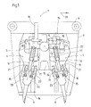
- a in Fig. 1 and 2 visible tamping unit 1 for tamping Thresholds 2 of a track 3 is specially designed for use in switch sections trained and consists of a total of four on normal to one an arrow 29 indicated machine longitudinal direction guide columns 4 sliding units, of which only for the sake of simplicity one is shown.
- the tamping unit 1 has two in the machine longitudinal direction opposite each other and each by an auxiliary drive 5 mutually available, lever-shaped tamping tools 6.
- Each tamping tool 6 is in its lower end region with two tamping picks 7,8 connected, one of which continues from an assembly frame 9 distanced tamping pick 8 around a machine tool in the longitudinal direction Pivot axis 10 is pivotally mounted.
- the stuffing tool 6 is over a side axis that is normal to the machine's longitudinal direction and runs horizontally 11 pivotally mounted on a tool carrier 12. This is with a vibration drive 13 for mounting the auxiliary drives 5 and vibration the tamping pick 7.8 and equipped with guides 14 and one Height adjustable drive 15. Side and swivel axis 11, 10 run in normal direction to each other.
- a hydraulic swivel drive 16 For pivoting the tamping pimple further distanced from the unit frame 9 8 in the longitudinal direction of the threshold is a hydraulic swivel drive 16 intended.
- This has a piston rod 17 with an articulation point 18 and a hydraulic cylinder 19.
- a connecting plate 20 is attached to the end of the hydraulic cylinder 19, on which two hydraulic auxiliary drives 21 are mounted.
- These point each have a piston rod 22 with a pivot point 23 and one the connecting plate 20 attached hydraulic cylinder 24.
- the piston side Articulation points 23 of the two additional drives 21 are with articulation points 25 connected, the one on the tamping pick 8, about the pivot axis 10 pivotable pimple holder 26 are attached.
- the piston rod 17 of the swivel drive 16 is connected to articulation points 27 which are attached to the tamping tool 6.
- the two additional drives 21 are related their longitudinal axes parallel to the swivel drive 16 and in relation to a normal to the pivot axis 10 and in the longitudinal direction of the swivel drive 16 extending plane 28 arranged symmetrically.
- Fig. 2 is a first working position of the pivotally mounted in full lines Stopfpickels 8 shown this in the cross machine direction is positioned immediately adjacent to the adjacent tamping pick 7. In this working position, a normal tamping support is tucked under by simultaneously immersing both tamping axes 7,8 in the ballast. The piston rod is in this first working position of the tamping pick 8 17 of the swivel drive 16 and the two piston rods 22 of the Additional drives 21 each in an extended position.
Abstract
Description
Claims (5)
- Stopfaggregat (1) zum Unterstopfen von Schwellen (2) eines Gleises (3), mit durch Beistellantriebe (5) paarweise zueinander beistellbaren, um eine Beistellachse (11) verschwenkbar auf einem höhenverstellbaren Werkzeugträger (12) gelagerten Stopfwerkzeugen (6), denen in ihrem unteren Endbereich jeweils wenigstens ein zum Eintauchen in Schotter vorgesehener Stopfpickel (7,8) zugeordnet ist, der um eine senkrecht zur Beistellachse (11) verlaufende Schwenkachse (10) verschwenkbar am Stopfwerkzeug (6) gelagert und durch eine Anlenkstelle (25) mit einem als Hydraulikzylinder ausgebildeten Schwenkantrieb (16) zum Verschwenken des Stopfpickels (8) in Schwellen längsrichtung verbunden ist, wobei der Schwenkantrieb (16) über eine Anlenkstelle (27) am Stopfwerkzeug (6) angelenkt ist, dadurch gekennzeichnet, daß der Schwenkantrieb (16) mit einem Zusatzantrieb (21) verbunden und an einer der beiden Anlenkstellen (27) angelenkt ist, während der Zusatzantrieb (21) an der weiteren Anlenkstelle (25) gelagert ist.
- Stopfaggregat nach Anspruch 1, dadurch gekennzeichnet, daß der Zusatzantrieb (21) parallel zum Schwenkantrieb (16) angeordnet und als Hydraulikzylinder (24) ausgebildet ist.
- Stopfaggregat nach Anspruch 1 oder 2, dadurch gekennzeichnet, daß in bezug auf eine normal zur Schwenkachse (10) und in Längsrichtung des Schwenkantriebes (16) verlaufende Ebene (28) zwei Zusatzantriebe (21) symmetrisch angeordnet sind.
- Stopfaggregat nach Anspruch 3, dadurch gekennzeichnet, daß die beiden Zusatzantriebe (21) auf einer Verbindungsplatte (20) befestigt sind, die ihrerseits mit einem Hydraulikzylinder (19) des Schwenkantriebes (16) verbunden ist.
- Stopfaggregat nach einem der Ansprüche 1 bis 4, dadurch gekennzeichnet, daß der Kolbenhub des Zusatzantriebes (21) für eine Verschwenkung des Stopfpickels (8) von einer ersten in eine zweite Arbeitsposition ausgebildet ist.
Applications Claiming Priority (3)
| Application Number | Priority Date | Filing Date | Title |
|---|---|---|---|
| AT0174097A ATA174097A (de) | 1997-10-14 | 1997-10-14 | Stopfaggregat |
| AT174097 | 1997-10-14 | ||
| AT1740/97 | 1997-10-14 |
Publications (2)
| Publication Number | Publication Date |
|---|---|
| EP0909852A1 true EP0909852A1 (de) | 1999-04-21 |
| EP0909852B1 EP0909852B1 (de) | 2002-09-04 |
Family
ID=3519985
Family Applications (1)
| Application Number | Title | Priority Date | Filing Date |
|---|---|---|---|
| EP98890251A Expired - Lifetime EP0909852B1 (de) | 1997-10-14 | 1998-08-26 | Stopfaggregat |
Country Status (13)
| Country | Link |
|---|---|
| US (1) | US6067910A (de) |
| EP (1) | EP0909852B1 (de) |
| JP (1) | JP3980771B2 (de) |
| CN (1) | CN1102977C (de) |
| AT (2) | ATA174097A (de) |
| AU (1) | AU731270B2 (de) |
| CA (1) | CA2250639C (de) |
| CZ (1) | CZ288290B6 (de) |
| DE (1) | DE59805389D1 (de) |
| DK (1) | DK0909852T3 (de) |
| ES (1) | ES2182262T3 (de) |
| PL (1) | PL191787B1 (de) |
| RU (1) | RU2158796C2 (de) |
Cited By (4)
| Publication number | Priority date | Publication date | Assignee | Title |
|---|---|---|---|---|
| CN101481896B (zh) * | 2008-01-12 | 2011-12-28 | 襄樊金鹰轨道车辆有限责任公司 | 一种道岔捣固装置 |
| CN107849827A (zh) * | 2015-08-21 | 2018-03-27 | 普拉塞-陶依尔铁路出口股份有限公司 | 捣固设备 |
| WO2019165483A1 (de) * | 2018-03-02 | 2019-09-06 | Hp3 Real Gmbh | Stopfaggregat für eine gleisstopfmaschine |
| WO2022087643A1 (de) * | 2020-10-28 | 2022-05-05 | Hp3 Real Gmbh | Stopfaggregat für eine gleisstopfmaschine |
Families Citing this family (6)
| Publication number | Priority date | Publication date | Assignee | Title |
|---|---|---|---|---|
| US6978718B2 (en) * | 2004-03-04 | 2005-12-27 | Seyrlehner Georg J | Tamping device and method of tamping a railroad track's ballast |
| SG11201509170PA (en) | 2013-07-02 | 2016-01-28 | Saudi Basic Ind Corp | Process and installation for the conversion of crude oil to petrochemicals having an improved btx yield |
| CN109593556A (zh) | 2013-07-02 | 2019-04-09 | 沙特基础工业公司 | 用于将原油转化成具有改进的丙烯产率的石化品的方法和设施 |
| USD789994S1 (en) | 2015-08-05 | 2017-06-20 | Nordco Inc. | Tamper tool |
| AU2016204901A1 (en) * | 2015-08-10 | 2017-03-02 | Nordco Inc. | Tamper Tool and Associated Holder |
| JP7130207B2 (ja) * | 2018-11-19 | 2022-09-05 | 株式会社交通建設 | 軌道整備装置及び軌道整備方法 |
Citations (3)
| Publication number | Priority date | Publication date | Assignee | Title |
|---|---|---|---|---|
| FR2526882A1 (fr) * | 1982-04-05 | 1983-11-18 | Genet Gerard | Batterie de verins a double effet |
| US4537135A (en) | 1983-05-04 | 1985-08-27 | Franz Plasser Bahnbaumaschinen Industriegesellschaft M.B.H. | Tamping unit |
| US5269226A (en) | 1991-10-24 | 1993-12-14 | Franz Plasser Bahnbaumaschinen-Industriegesellschaft M.B.H. | Ballast tamping assembly with mechanical stops on tamping picks for limiting pivotal movement |
-
1997
- 1997-10-14 AT AT0174097A patent/ATA174097A/de not_active Application Discontinuation
-
1998
- 1998-08-26 AT AT98890251T patent/ATE223537T1/de active
- 1998-08-26 DK DK98890251T patent/DK0909852T3/da active
- 1998-08-26 EP EP98890251A patent/EP0909852B1/de not_active Expired - Lifetime
- 1998-08-26 ES ES98890251T patent/ES2182262T3/es not_active Expired - Lifetime
- 1998-08-26 DE DE59805389T patent/DE59805389D1/de not_active Expired - Lifetime
- 1998-09-14 US US09/152,832 patent/US6067910A/en not_active Expired - Lifetime
- 1998-09-15 CZ CZ19982942A patent/CZ288290B6/cs not_active IP Right Cessation
- 1998-10-08 PL PL329087A patent/PL191787B1/pl not_active IP Right Cessation
- 1998-10-13 JP JP29078498A patent/JP3980771B2/ja not_active Expired - Fee Related
- 1998-10-13 CN CN98120948A patent/CN1102977C/zh not_active Expired - Fee Related
- 1998-10-13 AU AU88436/98A patent/AU731270B2/en not_active Ceased
- 1998-10-14 CA CA002250639A patent/CA2250639C/en not_active Expired - Fee Related
- 1998-10-14 RU RU98118737/28A patent/RU2158796C2/ru not_active IP Right Cessation
Patent Citations (3)
| Publication number | Priority date | Publication date | Assignee | Title |
|---|---|---|---|---|
| FR2526882A1 (fr) * | 1982-04-05 | 1983-11-18 | Genet Gerard | Batterie de verins a double effet |
| US4537135A (en) | 1983-05-04 | 1985-08-27 | Franz Plasser Bahnbaumaschinen Industriegesellschaft M.B.H. | Tamping unit |
| US5269226A (en) | 1991-10-24 | 1993-12-14 | Franz Plasser Bahnbaumaschinen-Industriegesellschaft M.B.H. | Ballast tamping assembly with mechanical stops on tamping picks for limiting pivotal movement |
Cited By (8)
| Publication number | Priority date | Publication date | Assignee | Title |
|---|---|---|---|---|
| CN101481896B (zh) * | 2008-01-12 | 2011-12-28 | 襄樊金鹰轨道车辆有限责任公司 | 一种道岔捣固装置 |
| CN107849827A (zh) * | 2015-08-21 | 2018-03-27 | 普拉塞-陶依尔铁路出口股份有限公司 | 捣固设备 |
| CN107849827B (zh) * | 2015-08-21 | 2019-12-13 | 普拉塞-陶依尔铁路出口股份有限公司 | 捣固设备 |
| WO2019165483A1 (de) * | 2018-03-02 | 2019-09-06 | Hp3 Real Gmbh | Stopfaggregat für eine gleisstopfmaschine |
| AT521008A1 (de) * | 2018-03-02 | 2019-09-15 | Hp3 Real Gmbh | Stopfaggregat für eine Gleisstopfmaschine |
| AT521008B1 (de) * | 2018-03-02 | 2020-02-15 | Hp3 Real Gmbh | Stopfaggregat für eine Gleisstopfmaschine |
| US11807995B2 (en) | 2018-03-02 | 2023-11-07 | Hp3 Real Gmbh | Tamping assembly for a track tamping machine |
| WO2022087643A1 (de) * | 2020-10-28 | 2022-05-05 | Hp3 Real Gmbh | Stopfaggregat für eine gleisstopfmaschine |
Also Published As
| Publication number | Publication date |
|---|---|
| CA2250639A1 (en) | 1999-04-14 |
| AU8843698A (en) | 1999-05-06 |
| CN1214391A (zh) | 1999-04-21 |
| CN1102977C (zh) | 2003-03-12 |
| CZ294298A3 (cs) | 1999-05-12 |
| EP0909852B1 (de) | 2002-09-04 |
| CA2250639C (en) | 2005-11-08 |
| JP3980771B2 (ja) | 2007-09-26 |
| JPH11200305A (ja) | 1999-07-27 |
| RU2158796C2 (ru) | 2000-11-10 |
| ATE223537T1 (de) | 2002-09-15 |
| ES2182262T3 (es) | 2003-03-01 |
| PL191787B1 (pl) | 2006-07-31 |
| US6067910A (en) | 2000-05-30 |
| DE59805389D1 (de) | 2002-10-10 |
| DK0909852T3 (da) | 2002-11-11 |
| CZ288290B6 (en) | 2001-05-16 |
| PL329087A1 (en) | 1999-04-26 |
| AU731270B2 (en) | 2001-03-29 |
| ATA174097A (de) | 1999-01-15 |
Similar Documents
| Publication | Publication Date | Title |
|---|---|---|
| CH641859A5 (de) | Fahrbare gleisbearbeitungsmaschine fuer weichen, kreuzungen und streckengleise. | |
| AT400341B (de) | Maschine zum schwellenwechseln | |
| EP0909852B1 (de) | Stopfaggregat | |
| EP0539347B1 (de) | Stopfaggregat | |
| AT400337B (de) | Gleisstopfmaschine mit in gleisquerrichtung verstellbaren stopfeinheiten | |
| EP0584055B1 (de) | Gleisstopfmaschine zum Unterstopfen von Weichen und Kreuzungen eines Gleises | |
| DD292492A5 (de) | Fahrbare gleisstopf-, nivellier- und richtmaschine | |
| DE3015283A1 (de) | Verfahren und gleisfahrbare maschine zum entfernen von unregelmaessigkeiten an der schienenkopfoberflaeche verlegter gleise | |
| EP0572370B1 (de) | Schotterpflug | |
| DE2610520A1 (de) | Gleisstopfmaschine, insbesondere gleisstopf- und nivelliermaschine | |
| DE3026883C2 (de) | Fahrbare Gleisstopfmaschine | |
| CH622302A5 (en) | Track-tamping machine, in particular for tamping down track points, crossings and the like | |
| DE3409848A1 (de) | Fahrbare gleisstopf-nivellier- und richtmaschine | |
| DE1658339B2 (de) | Gleisstopf- und richtmaschine | |
| EP0784121B1 (de) | Gleisstopfmaschine | |
| DE3814732C2 (de) | Gleisverfahrbare Vorrichtung zum Räumen bzw. Planieren des Schotters eines Gleises mit Querschwellen | |
| DE3425637C2 (de) | ||
| DE3110832A1 (de) | Gleisbaumschine mit gleislage-korrekturvorichtung | |
| EP0775779B1 (de) | Stopfaggregat | |
| DD293853A5 (de) | Fahrbare gleisstopfmaschine | |
| DE2651951C2 (de) | Maschine zum Unterstopfen der Querschwellen eines Gleises | |
| DE2602161A1 (de) | Gleisstopfmaschine | |
| DD141538A5 (de) | Gleisstopfmaschine | |
| DE3015289A1 (de) | Gleisverfahrbare hobel-maschine mit hobel-werkzeug | |
| DE3205511C2 (de) |
Legal Events
| Date | Code | Title | Description |
|---|---|---|---|
| PUAI | Public reference made under article 153(3) epc to a published international application that has entered the european phase |
Free format text: ORIGINAL CODE: 0009012 |
|
| AK | Designated contracting states |
Kind code of ref document: A1 Designated state(s): AT BE CH DE DK ES FI FR GB IT LI NL SE |
|
| AX | Request for extension of the european patent |
Free format text: AL;LT;LV;MK;RO;SI |
|
| 17P | Request for examination filed |
Effective date: 19990825 |
|
| AKX | Designation fees paid |
Free format text: AT BE CH DE DK ES FI FR GB IT LI NL SE |
|
| GRAG | Despatch of communication of intention to grant |
Free format text: ORIGINAL CODE: EPIDOS AGRA |
|
| GRAG | Despatch of communication of intention to grant |
Free format text: ORIGINAL CODE: EPIDOS AGRA |
|
| GRAH | Despatch of communication of intention to grant a patent |
Free format text: ORIGINAL CODE: EPIDOS IGRA |
|
| 17Q | First examination report despatched |
Effective date: 20020215 |
|
| GRAH | Despatch of communication of intention to grant a patent |
Free format text: ORIGINAL CODE: EPIDOS IGRA |
|
| GRAA | (expected) grant |
Free format text: ORIGINAL CODE: 0009210 |
|
| AK | Designated contracting states |
Kind code of ref document: B1 Designated state(s): AT BE CH DE DK ES FI FR GB IT LI NL SE |
|
| REF | Corresponds to: |
Ref document number: 223537 Country of ref document: AT Date of ref document: 20020915 Kind code of ref document: T |
|
| REG | Reference to a national code |
Ref country code: GB Ref legal event code: FG4D Free format text: NOT ENGLISH |
|
| REG | Reference to a national code |
Ref country code: CH Ref legal event code: EP |
|
| GBT | Gb: translation of ep patent filed (gb section 77(6)(a)/1977) |
Effective date: 20020904 |
|
| REF | Corresponds to: |
Ref document number: 59805389 Country of ref document: DE Date of ref document: 20021010 |
|
| REG | Reference to a national code |
Ref country code: DK Ref legal event code: T3 |
|
| ET | Fr: translation filed | ||
| REG | Reference to a national code |
Ref country code: ES Ref legal event code: FG2A Ref document number: 2182262 Country of ref document: ES Kind code of ref document: T3 |
|
| PLBE | No opposition filed within time limit |
Free format text: ORIGINAL CODE: 0009261 |
|
| STAA | Information on the status of an ep patent application or granted ep patent |
Free format text: STATUS: NO OPPOSITION FILED WITHIN TIME LIMIT |
|
| 26N | No opposition filed |
Effective date: 20030605 |
|
| PGFP | Annual fee paid to national office [announced via postgrant information from national office to epo] |
Ref country code: DK Payment date: 20110722 Year of fee payment: 14 |
|
| PGFP | Annual fee paid to national office [announced via postgrant information from national office to epo] |
Ref country code: GB Payment date: 20120629 Year of fee payment: 15 |
|
| PGFP | Annual fee paid to national office [announced via postgrant information from national office to epo] |
Ref country code: FI Payment date: 20120720 Year of fee payment: 15 Ref country code: SE Payment date: 20120725 Year of fee payment: 15 |
|
| PGFP | Annual fee paid to national office [announced via postgrant information from national office to epo] |
Ref country code: FR Payment date: 20120808 Year of fee payment: 15 Ref country code: IT Payment date: 20120824 Year of fee payment: 15 Ref country code: BE Payment date: 20120725 Year of fee payment: 15 Ref country code: ES Payment date: 20120720 Year of fee payment: 15 |
|
| PGFP | Annual fee paid to national office [announced via postgrant information from national office to epo] |
Ref country code: DE Payment date: 20121024 Year of fee payment: 15 Ref country code: NL Payment date: 20120727 Year of fee payment: 15 |
|
| PGFP | Annual fee paid to national office [announced via postgrant information from national office to epo] |
Ref country code: AT Payment date: 20120711 Year of fee payment: 15 |
|
| BERE | Be: lapsed |
Owner name: FRANZ *PLASSER BAHNBAUMASCHINEN- INDUSTRIEG.- M.B. Effective date: 20130831 |
|
| REG | Reference to a national code |
Ref country code: NL Ref legal event code: V1 Effective date: 20140301 |
|
| REG | Reference to a national code |
Ref country code: DK Ref legal event code: EBP Effective date: 20130831 |
|
| REG | Reference to a national code |
Ref country code: SE Ref legal event code: EUG |
|
| REG | Reference to a national code |
Ref country code: AT Ref legal event code: MM01 Ref document number: 223537 Country of ref document: AT Kind code of ref document: T Effective date: 20130826 |
|
| GBPC | Gb: european patent ceased through non-payment of renewal fee |
Effective date: 20130826 |
|
| PG25 | Lapsed in a contracting state [announced via postgrant information from national office to epo] |
Ref country code: SE Free format text: LAPSE BECAUSE OF NON-PAYMENT OF DUE FEES Effective date: 20130827 Ref country code: DE Free format text: LAPSE BECAUSE OF NON-PAYMENT OF DUE FEES Effective date: 20140301 Ref country code: NL Free format text: LAPSE BECAUSE OF NON-PAYMENT OF DUE FEES Effective date: 20140301 Ref country code: FI Free format text: LAPSE BECAUSE OF NON-PAYMENT OF DUE FEES Effective date: 20130826 |
|
| REG | Reference to a national code |
Ref country code: DE Ref legal event code: R119 Ref document number: 59805389 Country of ref document: DE Effective date: 20140301 |
|
| REG | Reference to a national code |
Ref country code: FR Ref legal event code: ST Effective date: 20140430 |
|
| PG25 | Lapsed in a contracting state [announced via postgrant information from national office to epo] |
Ref country code: AT Free format text: LAPSE BECAUSE OF NON-PAYMENT OF DUE FEES Effective date: 20130826 Ref country code: BE Free format text: LAPSE BECAUSE OF NON-PAYMENT OF DUE FEES Effective date: 20130831 Ref country code: IT Free format text: LAPSE BECAUSE OF NON-PAYMENT OF DUE FEES Effective date: 20130826 |
|
| PG25 | Lapsed in a contracting state [announced via postgrant information from national office to epo] |
Ref country code: GB Free format text: LAPSE BECAUSE OF NON-PAYMENT OF DUE FEES Effective date: 20130826 |
|
| PG25 | Lapsed in a contracting state [announced via postgrant information from national office to epo] |
Ref country code: FR Free format text: LAPSE BECAUSE OF NON-PAYMENT OF DUE FEES Effective date: 20130902 |
|
| REG | Reference to a national code |
Ref country code: ES Ref legal event code: FD2A Effective date: 20140908 |
|
| PG25 | Lapsed in a contracting state [announced via postgrant information from national office to epo] |
Ref country code: DK Free format text: LAPSE BECAUSE OF NON-PAYMENT OF DUE FEES Effective date: 20130831 |
|
| PG25 | Lapsed in a contracting state [announced via postgrant information from national office to epo] |
Ref country code: ES Free format text: LAPSE BECAUSE OF NON-PAYMENT OF DUE FEES Effective date: 20130827 |
|
| PGFP | Annual fee paid to national office [announced via postgrant information from national office to epo] |
Ref country code: CH Payment date: 20160711 Year of fee payment: 19 |
|
| REG | Reference to a national code |
Ref country code: CH Ref legal event code: PL |
|
| PG25 | Lapsed in a contracting state [announced via postgrant information from national office to epo] |
Ref country code: CH Free format text: LAPSE BECAUSE OF NON-PAYMENT OF DUE FEES Effective date: 20170831 Ref country code: LI Free format text: LAPSE BECAUSE OF NON-PAYMENT OF DUE FEES Effective date: 20170831 |