EP0905830B1 - Anschlussvorrichtung mit Steckanschlüssen - Google Patents
Anschlussvorrichtung mit Steckanschlüssen Download PDFInfo
- Publication number
- EP0905830B1 EP0905830B1 EP98117823A EP98117823A EP0905830B1 EP 0905830 B1 EP0905830 B1 EP 0905830B1 EP 98117823 A EP98117823 A EP 98117823A EP 98117823 A EP98117823 A EP 98117823A EP 0905830 B1 EP0905830 B1 EP 0905830B1
- Authority
- EP
- European Patent Office
- Prior art keywords
- housing
- plug
- contacts
- connections
- connecting device
- Prior art date
- Legal status (The legal status is an assumption and is not a legal conclusion. Google has not performed a legal analysis and makes no representation as to the accuracy of the status listed.)
- Expired - Lifetime
Links
- 230000003287 optical effect Effects 0.000 claims abstract description 21
- 239000013307 optical fiber Substances 0.000 claims abstract description 5
- 239000004020 conductor Substances 0.000 claims abstract description 4
- 210000002105 tongue Anatomy 0.000 claims description 8
- 230000008878 coupling Effects 0.000 abstract 1
- 238000010168 coupling process Methods 0.000 abstract 1
- 238000005859 coupling reaction Methods 0.000 abstract 1
- 230000013011 mating Effects 0.000 description 17
- 238000003780 insertion Methods 0.000 description 5
- 230000037431 insertion Effects 0.000 description 5
- 238000006073 displacement reaction Methods 0.000 description 2
- 238000009413 insulation Methods 0.000 description 2
- 241000233805 Phoenix Species 0.000 description 1
- 239000000835 fiber Substances 0.000 description 1
- 230000007704 transition Effects 0.000 description 1
Images


Classifications
-
- H—ELECTRICITY
- H01—ELECTRIC ELEMENTS
- H01R—ELECTRICALLY-CONDUCTIVE CONNECTIONS; STRUCTURAL ASSOCIATIONS OF A PLURALITY OF MUTUALLY-INSULATED ELECTRICAL CONNECTING ELEMENTS; COUPLING DEVICES; CURRENT COLLECTORS
- H01R9/00—Structural associations of a plurality of mutually-insulated electrical connecting elements, e.g. terminal strips or terminal blocks; Terminals or binding posts mounted upon a base or in a case; Bases therefor
- H01R9/22—Bases, e.g. strip, block, panel
- H01R9/24—Terminal blocks
- H01R9/2416—Means for guiding or retaining wires or cables connected to terminal blocks
-
- G—PHYSICS
- G02—OPTICS
- G02B—OPTICAL ELEMENTS, SYSTEMS OR APPARATUS
- G02B6/00—Light guides; Structural details of arrangements comprising light guides and other optical elements, e.g. couplings
- G02B6/24—Coupling light guides
- G02B6/36—Mechanical coupling means
- G02B6/38—Mechanical coupling means having fibre to fibre mating means
- G02B6/3807—Dismountable connectors, i.e. comprising plugs
- G02B6/381—Dismountable connectors, i.e. comprising plugs of the ferrule type, e.g. fibre ends embedded in ferrules, connecting a pair of fibres
- G02B6/3817—Dismountable connectors, i.e. comprising plugs of the ferrule type, e.g. fibre ends embedded in ferrules, connecting a pair of fibres containing optical and electrical conductors
-
- G—PHYSICS
- G02—OPTICS
- G02B—OPTICAL ELEMENTS, SYSTEMS OR APPARATUS
- G02B6/00—Light guides; Structural details of arrangements comprising light guides and other optical elements, e.g. couplings
- G02B6/24—Coupling light guides
- G02B6/42—Coupling light guides with opto-electronic elements
- G02B6/4201—Packages, e.g. shape, construction, internal or external details
- G02B6/4256—Details of housings
-
- H—ELECTRICITY
- H01—ELECTRIC ELEMENTS
- H01R—ELECTRICALLY-CONDUCTIVE CONNECTIONS; STRUCTURAL ASSOCIATIONS OF A PLURALITY OF MUTUALLY-INSULATED ELECTRICAL CONNECTING ELEMENTS; COUPLING DEVICES; CURRENT COLLECTORS
- H01R13/00—Details of coupling devices of the kinds covered by groups H01R12/70 or H01R24/00 - H01R33/00
- H01R13/58—Means for relieving strain on wire connection, e.g. cord grip, for avoiding loosening of connections between wires and terminals within a coupling device terminating a cable
- H01R13/59—Threaded ferrule or bolt operating in a direction parallel to the cable or wire
-
- H—ELECTRICITY
- H01—ELECTRIC ELEMENTS
- H01R—ELECTRICALLY-CONDUCTIVE CONNECTIONS; STRUCTURAL ASSOCIATIONS OF A PLURALITY OF MUTUALLY-INSULATED ELECTRICAL CONNECTING ELEMENTS; COUPLING DEVICES; CURRENT COLLECTORS
- H01R31/00—Coupling parts supported only by co-operation with counterpart
- H01R31/06—Intermediate parts for linking two coupling parts, e.g. adapter
-
- H—ELECTRICITY
- H01—ELECTRIC ELEMENTS
- H01R—ELECTRICALLY-CONDUCTIVE CONNECTIONS; STRUCTURAL ASSOCIATIONS OF A PLURALITY OF MUTUALLY-INSULATED ELECTRICAL CONNECTING ELEMENTS; COUPLING DEVICES; CURRENT COLLECTORS
- H01R9/00—Structural associations of a plurality of mutually-insulated electrical connecting elements, e.g. terminal strips or terminal blocks; Terminals or binding posts mounted upon a base or in a case; Bases therefor
- H01R9/22—Bases, e.g. strip, block, panel
- H01R9/24—Terminal blocks
- H01R9/2425—Structural association with built-in components
-
- H—ELECTRICITY
- H01—ELECTRIC ELEMENTS
- H01R—ELECTRICALLY-CONDUCTIVE CONNECTIONS; STRUCTURAL ASSOCIATIONS OF A PLURALITY OF MUTUALLY-INSULATED ELECTRICAL CONNECTING ELEMENTS; COUPLING DEVICES; CURRENT COLLECTORS
- H01R9/00—Structural associations of a plurality of mutually-insulated electrical connecting elements, e.g. terminal strips or terminal blocks; Terminals or binding posts mounted upon a base or in a case; Bases therefor
- H01R9/22—Bases, e.g. strip, block, panel
- H01R9/24—Terminal blocks
- H01R9/2491—Terminal blocks structurally associated with plugs or sockets
-
- H—ELECTRICITY
- H01—ELECTRIC ELEMENTS
- H01R—ELECTRICALLY-CONDUCTIVE CONNECTIONS; STRUCTURAL ASSOCIATIONS OF A PLURALITY OF MUTUALLY-INSULATED ELECTRICAL CONNECTING ELEMENTS; COUPLING DEVICES; CURRENT COLLECTORS
- H01R13/00—Details of coupling devices of the kinds covered by groups H01R12/70 or H01R24/00 - H01R33/00
- H01R13/66—Structural association with built-in electrical component
- H01R13/717—Structural association with built-in electrical component with built-in light source
- H01R13/7175—Light emitting diodes (LEDs)
-
- H—ELECTRICITY
- H01—ELECTRIC ELEMENTS
- H01R—ELECTRICALLY-CONDUCTIVE CONNECTIONS; STRUCTURAL ASSOCIATIONS OF A PLURALITY OF MUTUALLY-INSULATED ELECTRICAL CONNECTING ELEMENTS; COUPLING DEVICES; CURRENT COLLECTORS
- H01R31/00—Coupling parts supported only by co-operation with counterpart
- H01R31/06—Intermediate parts for linking two coupling parts, e.g. adapter
- H01R31/065—Intermediate parts for linking two coupling parts, e.g. adapter with built-in electric apparatus
Definitions
- the invention relates to a connecting device for a plurality of electrical conductors and / or optical waveguides, in particular a bus system with a housing and attachable plug-in connections arranged on one of the sides or on opposite sides of the rectangular in the basic form or square housing and inside the housing are connected by means of corresponding electrical contacts or optical transitions with electrical, electronic or photoelectric components.
- connection devices of this type are known from the catalog "PHOENIX CONTACT; II INTERBUS; '93 / 94".
- the plug-in connections are firmly installed on the relevant side of the housing.
- such housing have the shape of a cuboid or a parallelepiped, wherein on the connection sides outwardly projecting housing lugs are firmly formed, which carry a thread on which a respective head clamping screw cap can be placed, which is known as so-called PG-gland is.
- PG-gland is
- the invention is therefore an object of the invention to provide a connection device of the type mentioned above, which offers selectable connection options on the housing.
- connection device of the generic type by the features in the characterizing part of the claim that the plug connections relative to their direction of insertion by 90 degrees above the corner of the housing in electrical or light-transmitting contacting at the same point can be implemented.
- connection device is essential that the user can choose whether he arranges the plug-in connections on the longitudinal side or on the front side of the respective housing, wherein in the two respective positions offset by 90 degrees to each other, the contacting or engagement of the contacts the plug connections and the housing-side mating contacts always takes place at the same point, whereby a faulty contact is excluded.
- a plurality of the plug-in connections are combined to form a module, wherein one or more modules are connected to the housing of the connecting device and can occupy the two mutually offset by 90 degrees layers.
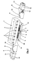
- Fig. 1 shows a housing 1, which has an elongated rectangular basic shape and therefore has the shape of a parallelepiped.
- openings 2 are provided which serve to accommodate not shown plug-in or screw connections, as they are necessary in a machine control for the connection of leading to actuators or sensors lines.
- optical display devices such as light emitting diodes 3, with which certain operating or control states can be signaled.
- the entire terminal device is used for connection to one or more bus systems, including further connections are provided, which will be discussed below.
- the housing 1 On the underside, the housing 1 has an attached base 4, which has a triangular in cross-section, prismatic shape, whereby at right angles to each other abutting stop surfaces 6 are formed on the base 4. These stop surfaces 6 are parallel to diagonal planes of the housing 1 and are perpendicular to the housing bottom.
- the housing 1 With the base 4, the housing 1 can be placed on a lower plate 5, which can also serve for attachment, therefore, 5 through holes 28 are provided in this lower plate.
- the lower plate 5 has in the form of steps a receiving contour 7 in order to receive the underside of the base 6 on the housing 1 in a form-fitting manner.
- the longitudinal or insertion direction can be arranged in an attached to the housing 1 arrangement either in the longitudinal direction or in the transverse direction.
- the modules 8 have a slanted stop surface 9 which extends to the longitudinal or insertion direction of the plug-in connections 10 and 11 at an angle of 45 degrees and otherwise stands upright, ie in attached to the housing 1 arrangement to the underside and the top of the lower plate 5 is vertical. Consequently, the relevant module 8 can be brought with its stop surface 9 in the position shown in Fig.
- the modules 8 have in the interior of the plug-in connections 10 associated electrical contacts 12 which cooperate with mating contacts 14 which are located in the space between the bottom of the housing 1 and the top of the lower 5.
- the other plug-in connections 11 of the modules 8 are used for connection to optical waveguides whose continuation in the module 8 likewise takes place via optical waveguides 18.
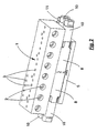
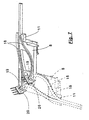
- Fig. 2 illustrates the assembled connection device, in which case the modules are arranged with their plug-in connections 10 and 11 in the longitudinal direction of the housing 1 at its end faces.
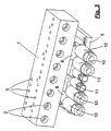
- the other option for the arrangement of the modules is shown in Fig. 3.
- the modules 8 are such between the lower plate 5 and the housing 1 recognized that the plug-in terminals 10 and 11 with their longitudinal or plug directions on the longitudinal side of the housing 1, ie lie transverse to the longitudinal direction.
- FIG. 3 that the modules 8 are upside down in relation to the arrangement according to FIG. 2.
- the electrical as well as the optical contact always takes place in the same place without any permutation, which is apparent from the figures explained below.
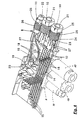
- the plug-in terminals 10 of a module 8 are provided for the connection of electrical lines 21, whose individual conductors are in contact with axially aligned insulation displacement terminals 27.
- This insulation displacement terminals 27 continue in the contacts 12, which are also shown together with the housing-side mating contacts 14 without further accessories in Figures 5 and 6.
- the contacts 13 are harp-like arranged in a plane parallel to each other and different lengths, the lengths of the contacts 13 are uniformly stepped.
- the contacts 12 have fork ends 13, with which they overlap contact tongues 15 of the housing-side mating contacts 14. This is done in the position in which the plug-in terminals 10 are in the longitudinal direction of the housing 1, in the manner that is shown in Fig. 5.
- the freestanding arranged contact tongues 15 of the mating contacts 14 are overlapped by their front sides 16 ago from the fork ends 13 of the plug-in connections 10 associated with contacts 12.
- the freestanding contact tongues 15 of the housing-side mating contacts 14 are overlapped from their longitudinal sides 17 ago.
- the contacts 12 and the mating contacts 14 do not collide with each other, they are arranged in mutually parallel, adjacent planes, wherein the contact tongues 15 at the ends of the mating contacts in the plane the contacts 12 and the fork ends 13 are bent.
- Contacts 12 are also the housing-side mating contacts 14 in opposite to the contacts 12 gradation unequal length, the gradation along a 45 degree line relative to the longitudinal direction of the contacts 12 and the mating contacts 14 respectively.
- the fork ends can be arranged on the housing-side mating contacts 14 and the end-side tongues on the contacts 12 of the plug-in connections 10 in an interchangeable version.
- the optical contact of the light guide 18 is made, which are associated with the plug-in connection 11 of the modules 8, which is provided for the connection of a fiber optic cable 22.
- FIG. 7 The two light guides 18, with their transmitting or receiving front ends 19, directly opposite an optical lens of a photoelectric receiving or transmitting device 20, which is firmly installed on the housing 1.
- the receiving or transmitting device 20 with their optical lens and the light guides 18 with their front ends 19 are also arranged in the direction of a diagonal plane at an angle of 45 degrees relative to the plug or longitudinal direction of the connector 11, which also here at offset by 90 degrees position of the module 8 in inverted arrangement the end faces 19 of the optical waveguide 18 and the optical lenses of the receiving and transmitting devices 20 in the same way face each other.
- Fig. 4 shows yet another peculiarity of the connection device, for the modules 8 is to aim for a low overall height.
- the introduction of the electrical leads 21 and the optical fiber cable 22 is carried out by screw caps 25, by means of which the lines 21, 22 are sealed in the usual manner and clamped relieved of strain.
- the modules For screwing the ringkappen 25, the modules have 8 loban arrangements 23, which are provided with an internal thread 24. Accordingly, the screw caps 25 have an external thread 26. This threading is unusual for the purpose mentioned, because in known designs, the screw caps have internal threads, accordingly, the associated housing lugs are equipped with an external thread.
Landscapes
- Physics & Mathematics (AREA)
- General Physics & Mathematics (AREA)
- Optics & Photonics (AREA)
- Connector Housings Or Holding Contact Members (AREA)
- Coupling Device And Connection With Printed Circuit (AREA)
- Optical Couplings Of Light Guides (AREA)
- Screw Conveyors (AREA)
- Mutual Connection Of Rods And Tubes (AREA)
- Mechanical Coupling Of Light Guides (AREA)
Description
- Die Erfindung bezieht sich auf eine Anschlußvorrichtung für eine Mehrzahl von elektrischen Leitern und/oder Lichtwellenleitern insbesondere eines Bussystems mit einem Gehäuse und daran anbringbaren Steckanschlüssen, die an einer der Seiten oder an einander gegenüberliegenden Seiten des in der Grundform rechteckigen oder quadratischen Gehäuses angeordnet und im Gehäuseinnern mittels entsprechender elektrischer Kontakte bzw. optischer Übergänge mit elektrischen, elektronischen oder photoelektrischen Bauteilen verbunden sind.
- Anschlußvorrichtungen dieser Art sind aus dem Katalog "PHOENIX CONTACT; II INTERBUS; '93/94" bekannt. Bei diesen Anschlußvorrichtungen sind die Steckanschlüsse an der betreffenden Gehäuseseite fest installiert. In der Regel haben solche Gehäuse die Form eines Quaders oder eines Parallelepipeds, wobei an den Anschlußseiten nach außen vorstehende Gehäuseansätze fest angeformt sind, die ein Gewinde tragen, auf die eine den betreffenden Leiter klemmende Schraubkappe aufgesetzt werden kann, was als sogenannte PG-Verschraubung bekannt ist. Für verschiedene Anschlußsysteme, die Leitungsein- bzw. -abgänge entweder an einer Gehäuselängsseite oder an einer Gehäusestirnseite erfordern, hat man bislang daran speziell angepaßte Gehäuseausbildungen vorsehen müssen.
- Der Erfindung liegt deshalb die Aufgabe zugrunde, eine Anschlußvorrichtung der eingangs genannten Art zu schaffen, die am Gehäuse wählbare Anschlußmöglichkeiten bietet.
- Diese Aufgabe wird bei einer Anschlußvorrichtung der gattungsbildenden Art durch die Merkmale im kennzeichnenden Teil des Anspruches gelöst, daß die Steckanschlüsse bezogen auf ihre Steckrichtung um 90 Grad über Eck an dem Gehäuse bei elektrischer oder lichtübertragender Kontaktierung an gleicher Stelle umsetzbar sind.
- Für die erfindungsgemäße Anschlußvorrichtung ist wesentlich, daß der Anwender wählen kann, ob er die Steckanschlüsse an der Längsseite oder an der Stirnseite des betreffenden Gehäuses anordnet, wobei in den beiden jeweiligen, um 90 Grad zueinander versetzten Positionen die Kontaktierung bzw. der Eingriff der Kontakte an den Steckanschlüssen und der gehäuseseitigen Gegenkontakte stets an derselben Stelle erfolgt, womit eine fehlerhafte Kontaktierung ausgeschlossen ist.
- In vorteilhafter Ausgestaltung nach der Erfindung sind mehrere der Steckanschlüsse zu einem Modul zusammengefaßt, wobei ein oder mehrere Module an dem Gehäuse der Anschlußvorrichtung anschließbar sind und daran die beiden zueinander um 90 Grad versetzten Lagen einnehmen können. Besonders zweckmäßige Ausgestaltungsmerkmale hinsichtlich der mechanischen Verbindung der Module mit dem Gehäuse und der Kontaktierung einer Mehrzahl vorhandener Kontakte ergeben sich aus den Unteransprüchen und aus der nachstehenden Beschreibung.
- Die Erfindung wird nachfolgend anhand der Zeichnung an einem Ausführungsbeispiel noch näher erläutert. Dabei zeigen:
- Fig. 1
- eine perspektivische, schräg von oben gesehene Darstellung einer Anschlußvorrichtung mit davon abgesprengt dargestellten Modulen, die jweils eine Mehrzahl von Steckanschlüssen aufweisen,
- Fig. 2
- eine der Fig. 1 entsprechende Darstellung der Anschlußvorrichtung mit den an das Gehäuse angesetzten Modulen bei stirnseitiger Lage der Steckanschlüsse,
- Fig. 3
- eine der Fig. 1 entsprechende Darstellung der Anschlußvorrichtung mit an das Gehäuse angesetzten Modulen bei längsseitiger Lage der Steckanschlüsse,
- Fig. 4
- eine perspektivische Innenansicht der Anschlußvorrichtung nach den Fig. 1 - 3 im Bereich der Kontaktierung der Steckanschlüsse,
- Fig. 5
- eine perspektivische Darstellung der miteinander kontaktierenden elektrischen Kontakte der Steckanschlüsse und der gehäuseseitigen Gegenkontakte bei stirnseitiger Anordnung der Steckanschlüsse am Gehäuse,
- Fig. 6
- eine perspektivische Darstellung der Kontakte der Steckanschlüsse und der gehäuseseitigen Gegenkontakte gemäß Fig. 5 jedoch bei längsseitiger Anordnung der Steckanschlüsse am Gehäuse und
- Fig. 7
- eine detaillierte perspektivische Darstellung des Lichtwellenleiteranschlusses der Module der Anschlußvorichtung gemäß den vorstehenden Figuren.
- Im einzelnen zeigt Fig. 1 ein Gehäuse 1, welches eine länglich rechteckige Grundform hat und deshalb die Gestalt eines Parallelepipeds aufweist. An einer der Längsseiten des Gehäuses 1 sind Öffnungen 2 vorhanden, die der Aufnahme nicht näher dargestellter Steck- oder Schraubanschlüsse dienen, wie sie bei einer Maschinensteuerung für den Anschluß von zu Aktoren oder Sensoren führenden Leitungen notwendig sind. An der Oberseite des Gehäuses finden sich optische Anzeigeeinrichtungen, wie Leuchtdioden 3, mit denen bestimmte Betriebs- oder Kontrollzustände signalisiert werden können. Vornehmlich dient die gesamte Anschlußvorrichtung zur Verbindung mit einem oder mehreren Bussystemen, wozu weitere Anschlüsse vorgesehen sind, auf die nachstehend noch eingegangen werden wird.
- Unterseitig hat das Gehäuse 1 einen angesetzten Sockel 4, der eine im Querschnitt dreieckige, prismatische Gestalt hat, wodurch im rechten Winkel zueinanderstehende Anschlagflächen 6 an dem Sockel 4 gebildet sind. Diese Anschlagflächen 6 verlaufen parallel zu Diagonalebenen des Gehäuses 1 und stehen senkrecht auf der Gehäuseunterseite. Mit dem Sockel 4 ist das Gehäuse 1 auf eine Untersetzplatte 5 aufsetzbar, die zugleich zur Befestigung dienen kann, deshalb sind in dieser Untersetzplatte 5 Durchgangslöcher 28 vorgesehen. Die Untersetzplatte 5 hat in Gestalt von Stufen eine Aufnahmekontur 7, um die Unterseite des Sockels 6 am Gehäuse 1 formschlüssig aufnehmen zu können.
- Zwischen der Oberseite der Untersetzplatte 5 und der Unterseite des Gehäuses 1 ist ein Zwischenraum gebildet, der zum Ansetzen von Modulen 8 dient. An den Modulen 8 sind mehrere Steckanschlüsse 10 und 11 zusammengefaßt, deren Längs- oder Steckrichtung in an das Gehäuse 1 angefügter Anordnung wahlweise in dessen Längsrichtung oder in dessen Querrichtung angeordnet werden kann. Dazu haben die Module 8 eine geschrägte Anschlagfläche 9, die zur Längs- oder Steckrichtung der Steckanschlüsse 10 und 11 unter einem Winkel von 45 Grad verläuft und im übrigen aufrecht steht, also in an das Gehäuse 1 angefügter Anordnung zu dessen Unterseite und zur Oberseite der Untersetzplatte 5 senkrecht steht. Folglich kann das betreffende Modul 8 mit seiner Anschlagfläche 9 in der in Fig. 1 dargestellten Position zur Anlage an der Anschlagfläche 6 am Gehäusesockel 4 gebracht werden, gleiches ist aber auch dann möglich, wenn das Modul 8 um eine Achse, die parallel zur Längs- oder Steckrichtung der Anschlüsse 10 und 11 liegt, um 180 Grad gedreht wird, wonach dann in der an den Gehäusesockel 4 angefügter Anordnung des Moduls 8 die Längs- bzw. Steckrichtung der Steckanschlüsse 10 und 11 rechtwinklig zu der in Fig. 1 wiedergegebenen Lage verläuft, was sich aus den nachfolgend noch erläuterten Figuren 2 und 3 ergibt.
- Die Module 8 weisen im Innern zu den Steckanschlüssen 10 gehörende elektrische Kontakte 12 auf, die mit Gegenkontakten 14 zusammenwirken, die sich in dem Raum zwischen der Unterseite des Gehäuses 1 und der Oberseite der Untersetzplatte 5 befinden. Die weiteren Steckanschlüsse 11 der Module 8 dienen der Verbindung mit Lichtwellenleitern, deren Fortsetzung im Modul 8 ebenfalls über Lichtwellenleiter 18 erfolgt.
- Fig. 2 veranschaulicht die zusammengefügte Anschlußvorrichtung, wobei hier die Module mit ihren Steckanschlüssen 10 und 11 in Längsrichtung des Gehäuses 1 an dessen Stirnseiten angeordnet sind. Die andere Wahlmöglichkeit für die Anordnung der Module zeigt Fig. 3. Hier sind die Module 8 derartig zwischen der Untersetzplatte 5 und dem Gehäuse 1 angesetzt, daß die Steckanschlüsse 10 und 11 mit ihren Längs- bzw. Steckrichtungen an der Längsseite des Gehäuses 1, also quer zu dessen Längsrichtung liegen. Man erkennt in Fig. 3 auch, daß die Module 8 gegenüber der Anordnung gemäß Fig. 2 auf dem Kopf stehen. Unabhängig von der Art der beiden um 90 Grad über Eck des Gehäuses 1 möglichen Anschlußpositionen der Module 8 erfolgt die elektrische wie auch die optische Kontaktierung immer an der gleichen Stelle ohne jegliche Vertauschung, was aus den nachstehend erläuterten Figuren deutlich wird.
- Aus Fig. 4 geht hervor, daß die Steckanschlüsse 10 eines Moduls 8 für den Anschluß elektrischer Leitungen 21 vorgesehen sind, deren einzelne Leiter mit axial ausgerichteten Schneidklemmen 27 in Kontakt stehen. Diese Schneidklemmen 27 setzen sich in den Kontakten 12 fort, die auch zusammen mit den gehäuseseitigen Gegenkontakten 14 ohne weiteres Beiwerk in den Figuren 5 und 6 dargestellt sind. Die Kontakte 13 sind harfenähnlich in einer Ebene parallel nebeneinander angeordnet und unterschiedlich lang, wobei die Längen der Kontakte 13 gleichmäßig gestuft sind. Die Kontakte 12 haben Gabelenden 13, mit denen sie Kontaktzungen 15 der gehäuseseitigen Gegenkontakte 14 übergreifen. Das geschieht in derjenigen Lage, in der die Steckanschlüsse 10 in Längsrichtung des Gehäuses 1 liegen, in derjenigen Weise, die in Fig. 5 wiedergegeben ist. Hier werden die freistehend angeordneten Kontaktzungen 15 der Gegenkontakte 14 von ihren Stirnseiten 16 her von den Gabelenden 13 der zu den Steckanschlüssen 10 zugehörigen Kontakte 12 übergriffen. In der dazu senkrechten, kopfstehenden Anordnung der Module 8, die in Fig. 3 dargestellt ist, erfolgt der Übergriff der Gabelenden 13 der zu den Steckanschlüssen 10 zugehörigen Kontakte 12 über die Kontaktzungen 15 der Gegenkontakte 14 in der in Fig. 6 wiedergegebenen Weise. Hier werden die freistehenden Kontaktzungen 15 der gehäuseseitigen Gegenkontakte 14 von ihren Längsseiten 17 her übergriffen. Damit hierbei die Kontakte 12 und die Gegenkontakte 14 nicht miteinander kollidieren, sind sie in miteinander parallelen, benachbarten Ebenen angeordnet, wobei die Kontaktzungen 15 an den Enden der Gegenkontakte in die Ebene der Kontakte 12 bzw. deren Gabelenden 13 abgekröpft sind. Ebenso wie die zu den Steckanschlüssen 10 zugehörigen. Kontakte 12 sind auch die gehäuseseitigen Gegenkontakte 14 in zu den Kontakten 12 entgegengesetzte Abstufung ungleich lang, wobei die Stufung entlang einer 45 Grad-Linie bezogen auf die Längsrichtung der Kontakte 12 bzw. der Gegenkontakte 14 jeweils verläuft. Dadurch ist es möglich, daß bei der in Fig. 5 dargestellten Längsausrichtung der Kontakte 12 und der Gegenkontakte 14 miteinander der Kontakteingriff an derselben Stelle erfolgt wie bei der in Fig. 6 wiedergegebenen Querausrichtung der Kontakte 12 relativ zu den Gegenkontakten 14, wobei hier die Kontakte 12 um 180 Grad gedreht kopfstehend angeordnet sind. Dadurch paßt sich die Stufung der Längen der einzelnen Kontakte 12 wiederum der Längenstufung der gehäuseseitigen Gegenkontakte 14 an. Grundsätzlich können in vertauschter Ausführung auch die Gabelenden an den gehäuseseitigen Gegenkontakten 14 und die endseitigen Zungen an den Kontakten 12 der Steckanschlüsse 10 angeordnet sein.
- In analoger Weise wird auch die optische Kontaktierung der Lichtleiter 18 vorgenommen, die dem Steckanschluß 11 der Module 8 zugeordnet sind, welcher für den Anschluß eines Lichtleiterkabels 22 vorgesehen ist. Dies veranschaulicht im einzelnen Fig. 7. Die beiden Lichtleiter 18 stehen mit ihren sendenden bzw. empfangenden Stirnenden 19 unmittelbar einer optischen Linse einer photoelektrischen Empfangs- bzw. Sendeeinrichtung 20 gegenüber, die fest am Gehäuse 1 installiert ist. Die Empfangs- bzw. Sendeeinrichtung 20 mit ihrer optischen Linse und die Lichtleiter 18 mit ihren Stirnenden 19 sind ebenfalls in Richtung einer Diagonalebene unter einem Winkel von 45 Grad relativ zur Steck- bzw. Längsrichtung des Steckanschlusses 11 angeordnet, womit auch hier bei um 90 Grad versetzter Lage des Moduls 8 in kopfstehender Anordnung sich die Stirnseiten 19 der Lichtwellenleiter 18 und die optischen Linsen der Empfangs- bzw. Sendeeinrichtungen 20 in gleicher Weise einander gegenüberstehen. Auch bei dem Lichtwellenleiteranschluß ist eine Kollisionsfreiheit dadurch sichergestellt, daß die beiden Empfangs- bzw. Sendeeinrichtungen 20 quer zu der erwähnten 45 Grad-Diagonalebene angeordnet sind und in Richtung dieser Ebene mit ihren optischen Linsen hintereinanderliegen, was entsprechend für die Stirnenden 19 der Lichtwellenleiter 18 gilt.
- Fig. 4 zeigt noch eine weitere Besonderheit der Anschlußvorrichtung, für deren Module 8 eine niedrige Bauhöhe anzustreben ist. Die Einführung der elektrischen Leitungen 21 und des Lichtleiterkabels 22 erfolgt durch Schraubkappen 25 hindurch, mittels derer die Leitungen 21, 22 in üblicher Weise abgedichtet und zugentlastet verklemmt werden. Für das Einschrauben der Schraubkappen 25 haben die Module 8 Schraubansätze 23, die mit einem Innengewinde 24 versehen sind. Entsprechend weisen die Schraubkappen 25 ein Außengewinde 26 auf. Diese Gewindeausbildung ist für den genannten Zweck unüblich, denn bei bekannten Ausführungen haben die Schraubkappen Innengewinde, entsprechend sind die zugehörenden Gehäuseansätze mit einem Außengewinde ausgestattet.
Claims (8)
- Anschlußvorrichtung für eine Mehrzahl von elektrischen Leitern (21) und/oder Lichtwellenleitern (22) insbesondere eines Bussystems mit einem in der Grundform rechteckigen oder quadratischen Gehäuse (1) und mit daran anbringbaren Steckanschlüssen (10, 11), die an einer der Seiten oder an einander gegenüberliegenden Seiten Gehäuses (1) angeordnet und im Gehäuseinnern mittels entsprechender elektrischer Kontakte (12-15) bzw. optischer Übergänge (19, 20) mit elektrischen, elektronischen oder photoelektrischen Bauteilen verbunden sind,
dadurch gekennzeichnet,
daß die Steckrichtung der Steckanschlüsse (10, 11) in Längsrichtung und in Querrichtung des Gehäuses (1) vorgesehen ist, daß die gehäuseseitigen elektrischen Gegenkontakte (14) und/oder die gehäuseseitige optische Sende- und Empfangseinrichtung (20) entlang einer unter einem Winkel von 45° zur Steckrichtung stehenden Diagonalebene des Gehäuses (1) angeordnet sind, daß sich die Steckanschlüsse (10, 11) an zumindest eindem Modul (8) befinden und ihre Kontakte (12) und/oder ihre sendenden und empfangenden Lichtleiterstirnenden (19) ebenfalls in Richtung einer unter einem Winkel von 45° zu ihrer Steckrichtung stehenden Diagonalebene angeordnet sind, wobei das Modul (8) mit den Steckanschlüssen (10, 11) bezogen auf die Steckrichtung um 90° über Eck am Gehäuse (1) umsetzbar ist und die elektrische und optische Kontaktierung nach dem Umsetzen an jeweils denselben Kontaktstellen bei um eine Achse parallel zur Steckrichtung um 180° gedrehter Lage des Moduls (8) erfolgt . - Anschlußvorrichtung nach Anspruch 1,
dadurch gekennzeichnet,
daß das Modul (8) und das Gehäuse (1) in der Kontaktlage aneinanderliegende Anschlagflächen (6, 9) haben, die aufrecht zur Steckrichtung der Steckanschlüsse (10, 11) unter einem Winkel von 45 Grad verlaufen. - Anschlußvorrichtung nach einem der Ansprüche 1 oder 2, dadurch gekennzeichnet,
daß das Gehäuse (1) auf eine Untersetzplatte (5) aufgesetzt ist, zwischen der und dem Gehäuse (1) ein oder mehrere Module gehalten sind. - Anschlußvorrichtung nach Anspruch 3,
dadurch gekennzeichnet,
daß das Gehäuse (1) einen unterseitigen Sockel (4) in Gestalt eines Prismas mit in oder parallel zu den Diagonalebenen des Gehäuses (1) verlaufenden Flächen als Anschlagflächen (6) für die Module (8) hat, wobei die Untersetzplatte (5) eine an die Grundfläche dieses Sockels (6) angepaßte Aufnahmekontur (7) an ihrer Oberseite aufweist. - Anschlußvorrichtung nach einem.der Ansprüche 1 - 4,
dadurch gekennzeichnet,
daß die Steckanschlüsse (10) der elektrischen Kontakte (12) mit in Steckrichtung offenen Gabelenden (13) und die Gegenkontakte (14) in oder am Gehäuse (1) freistehende Kontakt zungen (15) haben, wobei diese jeweils parallel zu einer der Gehäuseseiten angeordnet sind und von ihrer Stirnseite (16) oder von ihrer Längsseite (17) her von den Gabelenden (13) der Steckanschluß-Kontakte (12) übergreifbar sind. - Anschlußvorrichtung nach Anspruch 5,
dadurch gekennzeichnet,
daß die Kontakte (12) eines Steckanschlusses (10) oder die zweier oder mehrerer Steckanschlüsse (10) eines Moduls (8) harfenartig parallel nebeneinander in einer Ebene mit gestuften Längen und entsprechend die Gegenkontakte (14) am oder im Gehäuse (1) in entgegengesetzt gestufter Länge harfenartig parallel nebeneinander angeordnet sind, wobei die Kontakte (12) und die Gegenkontakte (14) in gefügter Anordnung in verschiedenen, parallelen Ebenen nebeneinander liegen und die Kontaktzungen (15) der Gegenkontakte (14) in die Ebene der Kontakte (12) bzw. deren Gabelenden (13) abgekröpft sind. - Anschlußvorrichtung nach einem der Ansprüche 1 - 6,
dadurch gekennzeichnet,
daß die Steckanschlüsse (11) für die Lichtübertragung zumindest einen zu dem jeweiligen optischen Übergang hinführenden Lichtwellenleiter (18) haben, der bezogen auf die Steckrichtung unter einem Winkel von 45 Grad mit seinem sendenden bzw. empfangenden Stirnende (19) einer im oder am Gehäuse (1) unter einem entsprechenden 45 Grad-Winkel installierten Empfangs- bzw. Sendeeinrichtung. (20) sowohl in einer ersten Kontaktlage als auch in einer dazu kopfstehenden, zweiten Kontaktlage an gleicher Stelle gegenübersteht. - Anschlußvorrichtung nach einem der Ansprüche 2 - 7,
dadurch gekennzeichnet,
daß die Steckanschlüsse (10, 11) oder das zumindest eine Modul (8) an der vom Gehäuse (1) abliegenden Seite Schraubansätze (23) mit einem Innengewinde (24) zur Aufnahme von Schraubkappen (25) mit einem Außengewinden (26) für die Leiterdurchführung und -klemmung haben.
Applications Claiming Priority (2)
| Application Number | Priority Date | Filing Date | Title |
|---|---|---|---|
| DE29717271U DE29717271U1 (de) | 1997-09-26 | 1997-09-26 | Anschlußvorrichtung mit Steckanschlüssen |
| DE29717271U | 1997-09-26 |
Publications (3)
| Publication Number | Publication Date |
|---|---|
| EP0905830A2 EP0905830A2 (de) | 1999-03-31 |
| EP0905830A3 EP0905830A3 (de) | 1999-12-22 |
| EP0905830B1 true EP0905830B1 (de) | 2006-05-03 |
Family
ID=8046523
Family Applications (1)
| Application Number | Title | Priority Date | Filing Date |
|---|---|---|---|
| EP98117823A Expired - Lifetime EP0905830B1 (de) | 1997-09-26 | 1998-09-19 | Anschlussvorrichtung mit Steckanschlüssen |
Country Status (3)
| Country | Link |
|---|---|
| EP (1) | EP0905830B1 (de) |
| AT (1) | ATE325449T1 (de) |
| DE (3) | DE29717271U1 (de) |
Families Citing this family (3)
| Publication number | Priority date | Publication date | Assignee | Title |
|---|---|---|---|---|
| DE10139202B4 (de) * | 2001-08-16 | 2007-01-11 | Phoenix Contact Gmbh & Co. Kg | Elektrischer Verteiler |
| DE102008019763B4 (de) | 2008-04-18 | 2019-02-21 | Phoenix Contact Gmbh & Co. Kg | Baueinheit mit einer Befestigungsvorrichtung zur lösbaren rastenden Halterung eines elektrischen Verteilers |
| CN106025732B (zh) * | 2016-04-01 | 2018-02-09 | 刘洋宏 | 带12v电源指示灯4路总线接线排 |
Family Cites Families (10)
| Publication number | Priority date | Publication date | Assignee | Title |
|---|---|---|---|---|
| US4744775A (en) * | 1987-02-12 | 1988-05-17 | Amp Incorporated | Electrical tap connector assembly |
| DE8711780U1 (de) * | 1987-08-31 | 1987-11-05 | Manfred Fladung GmbH, 8752 Mömbris | Vorrichtung zur Überprüfung von Steckerstiften |
| JPH0371581A (ja) * | 1989-08-09 | 1991-03-27 | Hitachi Ltd | 光電複合分岐コネクタ |
| DE4004550A1 (de) | 1990-02-14 | 1991-08-22 | Hans Brandner | Vorrichtung zum verschliessen einer kabeldurchfuehrungsoeffnung in einem schaltschrank |
| JPH0423622A (ja) * | 1990-05-18 | 1992-01-28 | Nec Corp | 光海底ケーブルの給電方法 |
| US5285511A (en) * | 1993-01-04 | 1994-02-08 | At&T Laboratories | Optoelectronic cable connector |
| DE4408029C1 (de) * | 1994-03-10 | 1995-08-31 | Amphenol Tuchel Elect | Verteiler-Gehäuse für einen Bus-Verteiler |
| DE19529181C2 (de) | 1995-08-08 | 1998-08-06 | Ifm Electronic Gmbh | Elektrisches oder elektronisches Gerät, insbesondere Näherungsschalter |
| DE19643072A1 (de) * | 1996-10-18 | 1998-04-23 | Alsthom Cge Alcatel | Optoelektronisches Bauelement |
| DE29706733U1 (de) | 1997-04-15 | 1998-08-13 | Phoenix Contact Gmbh & Co., 32825 Blomberg | Einrichtung für einen Aktor |
-
1997
- 1997-09-26 DE DE29717271U patent/DE29717271U1/de not_active Expired - Lifetime
-
1998
- 1998-09-18 DE DE29816737U patent/DE29816737U1/de not_active Expired - Lifetime
- 1998-09-19 DE DE59813525T patent/DE59813525D1/de not_active Expired - Lifetime
- 1998-09-19 EP EP98117823A patent/EP0905830B1/de not_active Expired - Lifetime
- 1998-09-19 AT AT98117823T patent/ATE325449T1/de active
Also Published As
| Publication number | Publication date |
|---|---|
| EP0905830A2 (de) | 1999-03-31 |
| ATE325449T1 (de) | 2006-06-15 |
| DE29816737U1 (de) | 1998-11-12 |
| DE59813525D1 (de) | 2006-06-08 |
| DE29717271U1 (de) | 1997-11-06 |
| EP0905830A3 (de) | 1999-12-22 |
Similar Documents
| Publication | Publication Date | Title |
|---|---|---|
| DE60100091T2 (de) | Optischer und elektrischer Steckverbinder | |
| DE60123984T2 (de) | Modulares verbindungssystem für ethernet-anwendungen im industriellen sektor | |
| EP1783521B1 (de) | Steckverbinder und Steckkupplung in Form eines RJ45-Anschlusssystems | |
| DE4402002B4 (de) | E/A-Module/ für einen Datenbus | |
| EP1504297B1 (de) | Hybrid-Steckverbindung | |
| DE102008058090B4 (de) | Ein-/Ausgabemodul für ein Automatisierungsgerät | |
| EP0112476B1 (de) | Elektrischer Installationsbausatz | |
| DE69008139T2 (de) | Bauelementensatz zum gleizeitigen elektrischen Verbinden einer Mehrzahl von modularen Selbstschaltern. | |
| EP0762165A2 (de) | Hybrider Steckverbinder mit modularen elektrischen und Lichtwellenleiter-Steckverbindungen | |
| CH693657A5 (de) | Hybrider Datenstecker. | |
| DE19652551C1 (de) | Hochpoliger geschirmter Kabelstecker | |
| EP0905830B1 (de) | Anschlussvorrichtung mit Steckanschlüssen | |
| DE60220234T2 (de) | Optisches Stecker-System | |
| DE4400484C3 (de) | Niederspannungsschaltgerät | |
| DE19743972A1 (de) | Elektronisches Ein-/Ausgabemodul | |
| DE102019119504B4 (de) | Steckverbinderteil mit einer Zugentlastung | |
| EP0057255B1 (de) | Leitungsstecker für Flachbaugruppen | |
| DE4401621C2 (de) | Kompakte, mehrpolige Steckverbindung | |
| DE3621223A1 (de) | Anschlussleiste fuer elektrische leitungen | |
| EP0821458A2 (de) | Leitungsverzweiger | |
| DE102018106880A1 (de) | Modularer Kontaktträger für einen Industriesteckverbinder | |
| DE102022101234A1 (de) | Anschlussdose | |
| DE60127581T2 (de) | Optisches Ringnetzwerk, optischer Steckverbinder und Hybridsteckverbinder | |
| LU102206B1 (de) | Klemme für elektrische Leitungen | |
| DE29701845U1 (de) | Schnittstelle mit einem opto-elektrischen Wandler |
Legal Events
| Date | Code | Title | Description |
|---|---|---|---|
| PUAI | Public reference made under article 153(3) epc to a published international application that has entered the european phase |
Free format text: ORIGINAL CODE: 0009012 |
|
| AK | Designated contracting states |
Kind code of ref document: A2 Designated state(s): AT BE CH DE FR GB IT LI NL |
|
| AX | Request for extension of the european patent |
Free format text: AL;LT;LV;MK;RO;SI |
|
| RIN1 | Information on inventor provided before grant (corrected) |
Inventor name: OSTER, VIKTOR DIPL.-ING. Inventor name: HANNIBAL, FRANK DIPL.-ING. Inventor name: METZGER,ANDREAS Inventor name: BRAND,JUERGEN,DIPL.-ING. Inventor name: GREWE,HARALD,DIPL.-ING. Inventor name: BERG,ROLAND Inventor name: FUERHOFF,ACHIM,DIPL.-ING. Inventor name: BEHR,THORSTEN,DIPL.-ING. |
|
| K1C1 | Correction of patent application (title page) published |
Effective date: 19990331 |
|
| RIN1 | Information on inventor provided before grant (corrected) |
Inventor name: OSTER,VIKTOR,DIPL.-ING. Inventor name: HANNIBAL,FRANK,DIPL.-ING. Inventor name: METZGER,ANDREAS Inventor name: BRAND,JUERGEN,DIPL.-ING. Inventor name: GREWE,HARALD,DIPL.-ING. Inventor name: BERG,ROLAND Inventor name: FUERHOFF,ACHIM,DIPL.-ING. Inventor name: BEHR,THORSTEN,DIPL.-ING. |
|
| PUAL | Search report despatched |
Free format text: ORIGINAL CODE: 0009013 |
|
| RIC1 | Information provided on ipc code assigned before grant |
Free format text: 6H 01R 31/06 A, 6G 02B 6/38 B, 6H 01R 9/24 B, 6H 01R 13/59 B, 6G 02B 6/42 B |
|
| AK | Designated contracting states |
Kind code of ref document: A3 Designated state(s): AT BE CH CY DE DK ES FI FR GB GR IE IT LI LU MC NL PT SE |
|
| AX | Request for extension of the european patent |
Free format text: AL;LT;LV;MK;RO;SI |
|
| 17P | Request for examination filed |
Effective date: 20000113 |
|
| RIN1 | Information on inventor provided before grant (corrected) |
Inventor name: OSTER,VIKTOR,DIPL.-ING. Inventor name: HANNIBAL,FRANK,DIPL.-ING. Inventor name: METZGER,ANDREAS Inventor name: BRAND,JUERGEN,DIPL.-ING. Inventor name: GREWE,HARALD,DIPL.-ING. Inventor name: BERG,ROLAND Inventor name: FUERHOFF,ACHIM,DIPL.-ING. Inventor name: BEHR,THORSTEN,DIPL.-ING. |
|
| AKX | Designation fees paid |
Free format text: AT BE CH DE FR GB IT LI NL |
|
| RAP1 | Party data changed (applicant data changed or rights of an application transferred) |
Owner name: PHOENIX CONTACT GMBH & CO. KG |
|
| 17Q | First examination report despatched |
Effective date: 20030402 |
|
| GRAP | Despatch of communication of intention to grant a patent |
Free format text: ORIGINAL CODE: EPIDOSNIGR1 |
|
| GRAS | Grant fee paid |
Free format text: ORIGINAL CODE: EPIDOSNIGR3 |
|
| GRAA | (expected) grant |
Free format text: ORIGINAL CODE: 0009210 |
|
| AK | Designated contracting states |
Kind code of ref document: B1 Designated state(s): AT BE CH DE FR GB IT LI NL |
|
| REG | Reference to a national code |
Ref country code: GB Ref legal event code: FG4D Free format text: NOT ENGLISH |
|
| REG | Reference to a national code |
Ref country code: CH Ref legal event code: EP |
|
| REF | Corresponds to: |
Ref document number: 59813525 Country of ref document: DE Date of ref document: 20060608 Kind code of ref document: P |
|
| GBT | Gb: translation of ep patent filed (gb section 77(6)(a)/1977) |
Effective date: 20060518 |
|
| REG | Reference to a national code |
Ref country code: CH Ref legal event code: NV Representative=s name: SCHMAUDER & PARTNER AG PATENTANWALTSBUERO |
|
| ET | Fr: translation filed | ||
| PLBE | No opposition filed within time limit |
Free format text: ORIGINAL CODE: 0009261 |
|
| STAA | Information on the status of an ep patent application or granted ep patent |
Free format text: STATUS: NO OPPOSITION FILED WITHIN TIME LIMIT |
|
| 26N | No opposition filed |
Effective date: 20070206 |
|
| REG | Reference to a national code |
Ref country code: CH Ref legal event code: PCAR Free format text: SCHMAUDER & PARTNER AG PATENT- UND MARKENANWAELTE VSP;ZWAENGIWEG 7;8038 ZUERICH (CH) |
|
| PGFP | Annual fee paid to national office [announced via postgrant information from national office to epo] |
Ref country code: CH Payment date: 20121001 Year of fee payment: 15 |
|
| PGFP | Annual fee paid to national office [announced via postgrant information from national office to epo] |
Ref country code: NL Payment date: 20120917 Year of fee payment: 15 Ref country code: AT Payment date: 20120924 Year of fee payment: 15 |
|
| PGFP | Annual fee paid to national office [announced via postgrant information from national office to epo] |
Ref country code: DE Payment date: 20130819 Year of fee payment: 16 |
|
| PGFP | Annual fee paid to national office [announced via postgrant information from national office to epo] |
Ref country code: GB Payment date: 20130925 Year of fee payment: 16 |
|
| PGFP | Annual fee paid to national office [announced via postgrant information from national office to epo] |
Ref country code: IT Payment date: 20130921 Year of fee payment: 16 |
|
| PGFP | Annual fee paid to national office [announced via postgrant information from national office to epo] |
Ref country code: BE Payment date: 20130925 Year of fee payment: 16 Ref country code: FR Payment date: 20130920 Year of fee payment: 16 |
|
| REG | Reference to a national code |
Ref country code: NL Ref legal event code: V1 Effective date: 20140401 |
|
| REG | Reference to a national code |
Ref country code: CH Ref legal event code: PL |
|
| REG | Reference to a national code |
Ref country code: AT Ref legal event code: MM01 Ref document number: 325449 Country of ref document: AT Kind code of ref document: T Effective date: 20130919 |
|
| PG25 | Lapsed in a contracting state [announced via postgrant information from national office to epo] |
Ref country code: CH Free format text: LAPSE BECAUSE OF NON-PAYMENT OF DUE FEES Effective date: 20130930 Ref country code: LI Free format text: LAPSE BECAUSE OF NON-PAYMENT OF DUE FEES Effective date: 20130930 |
|
| PG25 | Lapsed in a contracting state [announced via postgrant information from national office to epo] |
Ref country code: AT Free format text: LAPSE BECAUSE OF NON-PAYMENT OF DUE FEES Effective date: 20130919 Ref country code: NL Free format text: LAPSE BECAUSE OF NON-PAYMENT OF DUE FEES Effective date: 20140401 |
|
| REG | Reference to a national code |
Ref country code: DE Ref legal event code: R119 Ref document number: 59813525 Country of ref document: DE |
|
| GBPC | Gb: european patent ceased through non-payment of renewal fee |
Effective date: 20140919 |
|
| REG | Reference to a national code |
Ref country code: DE Ref legal event code: R119 Ref document number: 59813525 Country of ref document: DE Effective date: 20150401 |
|
| REG | Reference to a national code |
Ref country code: FR Ref legal event code: ST Effective date: 20150529 |
|
| PG25 | Lapsed in a contracting state [announced via postgrant information from national office to epo] |
Ref country code: BE Free format text: LAPSE BECAUSE OF NON-PAYMENT OF DUE FEES Effective date: 20140930 |
|
| PG25 | Lapsed in a contracting state [announced via postgrant information from national office to epo] |
Ref country code: GB Free format text: LAPSE BECAUSE OF NON-PAYMENT OF DUE FEES Effective date: 20140919 Ref country code: DE Free format text: LAPSE BECAUSE OF NON-PAYMENT OF DUE FEES Effective date: 20150401 |
|
| PG25 | Lapsed in a contracting state [announced via postgrant information from national office to epo] |
Ref country code: IT Free format text: LAPSE BECAUSE OF NON-PAYMENT OF DUE FEES Effective date: 20140919 Ref country code: FR Free format text: LAPSE BECAUSE OF NON-PAYMENT OF DUE FEES Effective date: 20140930 |