EP0905830B1 - Dispositif de raccordement avec des raccordements à fiches - Google Patents
Dispositif de raccordement avec des raccordements à fiches Download PDFInfo
- Publication number
- EP0905830B1 EP0905830B1 EP98117823A EP98117823A EP0905830B1 EP 0905830 B1 EP0905830 B1 EP 0905830B1 EP 98117823 A EP98117823 A EP 98117823A EP 98117823 A EP98117823 A EP 98117823A EP 0905830 B1 EP0905830 B1 EP 0905830B1
- Authority
- EP
- European Patent Office
- Prior art keywords
- housing
- plug
- contacts
- connections
- connecting device
- Prior art date
- Legal status (The legal status is an assumption and is not a legal conclusion. Google has not performed a legal analysis and makes no representation as to the accuracy of the status listed.)
- Expired - Lifetime
Links
Images


Classifications
-
- H—ELECTRICITY
- H01—ELECTRIC ELEMENTS
- H01R—ELECTRICALLY-CONDUCTIVE CONNECTIONS; STRUCTURAL ASSOCIATIONS OF A PLURALITY OF MUTUALLY-INSULATED ELECTRICAL CONNECTING ELEMENTS; COUPLING DEVICES; CURRENT COLLECTORS
- H01R9/00—Structural associations of a plurality of mutually-insulated electrical connecting elements, e.g. terminal strips or terminal blocks; Terminals or binding posts mounted upon a base or in a case; Bases therefor
- H01R9/22—Bases, e.g. strip, block, panel
- H01R9/24—Terminal blocks
- H01R9/2416—Means for guiding or retaining wires or cables connected to terminal blocks
-
- G—PHYSICS
- G02—OPTICS
- G02B—OPTICAL ELEMENTS, SYSTEMS OR APPARATUS
- G02B6/00—Light guides; Structural details of arrangements comprising light guides and other optical elements, e.g. couplings
- G02B6/24—Coupling light guides
- G02B6/36—Mechanical coupling means
- G02B6/38—Mechanical coupling means having fibre to fibre mating means
- G02B6/3807—Dismountable connectors, i.e. comprising plugs
- G02B6/381—Dismountable connectors, i.e. comprising plugs of the ferrule type, e.g. fibre ends embedded in ferrules, connecting a pair of fibres
- G02B6/3817—Dismountable connectors, i.e. comprising plugs of the ferrule type, e.g. fibre ends embedded in ferrules, connecting a pair of fibres containing optical and electrical conductors
-
- G—PHYSICS
- G02—OPTICS
- G02B—OPTICAL ELEMENTS, SYSTEMS OR APPARATUS
- G02B6/00—Light guides; Structural details of arrangements comprising light guides and other optical elements, e.g. couplings
- G02B6/24—Coupling light guides
- G02B6/42—Coupling light guides with opto-electronic elements
- G02B6/4201—Packages, e.g. shape, construction, internal or external details
- G02B6/4256—Details of housings
-
- H—ELECTRICITY
- H01—ELECTRIC ELEMENTS
- H01R—ELECTRICALLY-CONDUCTIVE CONNECTIONS; STRUCTURAL ASSOCIATIONS OF A PLURALITY OF MUTUALLY-INSULATED ELECTRICAL CONNECTING ELEMENTS; COUPLING DEVICES; CURRENT COLLECTORS
- H01R13/00—Details of coupling devices of the kinds covered by groups H01R12/70 or H01R24/00 - H01R33/00
- H01R13/58—Means for relieving strain on wire connection, e.g. cord grip, for avoiding loosening of connections between wires and terminals within a coupling device terminating a cable
- H01R13/59—Threaded ferrule or bolt operating in a direction parallel to the cable or wire
-
- H—ELECTRICITY
- H01—ELECTRIC ELEMENTS
- H01R—ELECTRICALLY-CONDUCTIVE CONNECTIONS; STRUCTURAL ASSOCIATIONS OF A PLURALITY OF MUTUALLY-INSULATED ELECTRICAL CONNECTING ELEMENTS; COUPLING DEVICES; CURRENT COLLECTORS
- H01R31/00—Coupling parts supported only by co-operation with counterpart
- H01R31/06—Intermediate parts for linking two coupling parts, e.g. adapter
-
- H—ELECTRICITY
- H01—ELECTRIC ELEMENTS
- H01R—ELECTRICALLY-CONDUCTIVE CONNECTIONS; STRUCTURAL ASSOCIATIONS OF A PLURALITY OF MUTUALLY-INSULATED ELECTRICAL CONNECTING ELEMENTS; COUPLING DEVICES; CURRENT COLLECTORS
- H01R9/00—Structural associations of a plurality of mutually-insulated electrical connecting elements, e.g. terminal strips or terminal blocks; Terminals or binding posts mounted upon a base or in a case; Bases therefor
- H01R9/22—Bases, e.g. strip, block, panel
- H01R9/24—Terminal blocks
- H01R9/2425—Structural association with built-in components
-
- H—ELECTRICITY
- H01—ELECTRIC ELEMENTS
- H01R—ELECTRICALLY-CONDUCTIVE CONNECTIONS; STRUCTURAL ASSOCIATIONS OF A PLURALITY OF MUTUALLY-INSULATED ELECTRICAL CONNECTING ELEMENTS; COUPLING DEVICES; CURRENT COLLECTORS
- H01R9/00—Structural associations of a plurality of mutually-insulated electrical connecting elements, e.g. terminal strips or terminal blocks; Terminals or binding posts mounted upon a base or in a case; Bases therefor
- H01R9/22—Bases, e.g. strip, block, panel
- H01R9/24—Terminal blocks
- H01R9/2491—Terminal blocks structurally associated with plugs or sockets
-
- H—ELECTRICITY
- H01—ELECTRIC ELEMENTS
- H01R—ELECTRICALLY-CONDUCTIVE CONNECTIONS; STRUCTURAL ASSOCIATIONS OF A PLURALITY OF MUTUALLY-INSULATED ELECTRICAL CONNECTING ELEMENTS; COUPLING DEVICES; CURRENT COLLECTORS
- H01R13/00—Details of coupling devices of the kinds covered by groups H01R12/70 or H01R24/00 - H01R33/00
- H01R13/66—Structural association with built-in electrical component
- H01R13/717—Structural association with built-in electrical component with built-in light source
- H01R13/7175—Light emitting diodes (LEDs)
-
- H—ELECTRICITY
- H01—ELECTRIC ELEMENTS
- H01R—ELECTRICALLY-CONDUCTIVE CONNECTIONS; STRUCTURAL ASSOCIATIONS OF A PLURALITY OF MUTUALLY-INSULATED ELECTRICAL CONNECTING ELEMENTS; COUPLING DEVICES; CURRENT COLLECTORS
- H01R31/00—Coupling parts supported only by co-operation with counterpart
- H01R31/06—Intermediate parts for linking two coupling parts, e.g. adapter
- H01R31/065—Intermediate parts for linking two coupling parts, e.g. adapter with built-in electric apparatus
Definitions
- the invention relates to a connecting device for a plurality of electrical conductors and / or optical waveguides, in particular a bus system with a housing and attachable plug-in connections arranged on one of the sides or on opposite sides of the rectangular in the basic form or square housing and inside the housing are connected by means of corresponding electrical contacts or optical transitions with electrical, electronic or photoelectric components.
- connection devices of this type are known from the catalog "PHOENIX CONTACT; II INTERBUS; '93 / 94".
- the plug-in connections are firmly installed on the relevant side of the housing.
- such housing have the shape of a cuboid or a parallelepiped, wherein on the connection sides outwardly projecting housing lugs are firmly formed, which carry a thread on which a respective head clamping screw cap can be placed, which is known as so-called PG-gland is.
- PG-gland is
- the invention is therefore an object of the invention to provide a connection device of the type mentioned above, which offers selectable connection options on the housing.
- connection device of the generic type by the features in the characterizing part of the claim that the plug connections relative to their direction of insertion by 90 degrees above the corner of the housing in electrical or light-transmitting contacting at the same point can be implemented.
- connection device is essential that the user can choose whether he arranges the plug-in connections on the longitudinal side or on the front side of the respective housing, wherein in the two respective positions offset by 90 degrees to each other, the contacting or engagement of the contacts the plug connections and the housing-side mating contacts always takes place at the same point, whereby a faulty contact is excluded.
- a plurality of the plug-in connections are combined to form a module, wherein one or more modules are connected to the housing of the connecting device and can occupy the two mutually offset by 90 degrees layers.
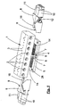
- Fig. 1 shows a housing 1, which has an elongated rectangular basic shape and therefore has the shape of a parallelepiped.
- openings 2 are provided which serve to accommodate not shown plug-in or screw connections, as they are necessary in a machine control for the connection of leading to actuators or sensors lines.
- optical display devices such as light emitting diodes 3, with which certain operating or control states can be signaled.
- the entire terminal device is used for connection to one or more bus systems, including further connections are provided, which will be discussed below.
- the housing 1 On the underside, the housing 1 has an attached base 4, which has a triangular in cross-section, prismatic shape, whereby at right angles to each other abutting stop surfaces 6 are formed on the base 4. These stop surfaces 6 are parallel to diagonal planes of the housing 1 and are perpendicular to the housing bottom.
- the housing 1 With the base 4, the housing 1 can be placed on a lower plate 5, which can also serve for attachment, therefore, 5 through holes 28 are provided in this lower plate.
- the lower plate 5 has in the form of steps a receiving contour 7 in order to receive the underside of the base 6 on the housing 1 in a form-fitting manner.
- the longitudinal or insertion direction can be arranged in an attached to the housing 1 arrangement either in the longitudinal direction or in the transverse direction.
- the modules 8 have a slanted stop surface 9 which extends to the longitudinal or insertion direction of the plug-in connections 10 and 11 at an angle of 45 degrees and otherwise stands upright, ie in attached to the housing 1 arrangement to the underside and the top of the lower plate 5 is vertical. Consequently, the relevant module 8 can be brought with its stop surface 9 in the position shown in Fig.
- the modules 8 have in the interior of the plug-in connections 10 associated electrical contacts 12 which cooperate with mating contacts 14 which are located in the space between the bottom of the housing 1 and the top of the lower 5.
- the other plug-in connections 11 of the modules 8 are used for connection to optical waveguides whose continuation in the module 8 likewise takes place via optical waveguides 18.
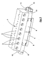
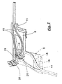
- Fig. 2 illustrates the assembled connection device, in which case the modules are arranged with their plug-in connections 10 and 11 in the longitudinal direction of the housing 1 at its end faces.
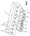
- the other option for the arrangement of the modules is shown in Fig. 3.
- the modules 8 are such between the lower plate 5 and the housing 1 recognized that the plug-in terminals 10 and 11 with their longitudinal or plug directions on the longitudinal side of the housing 1, ie lie transverse to the longitudinal direction.
- FIG. 3 that the modules 8 are upside down in relation to the arrangement according to FIG. 2.
- the electrical as well as the optical contact always takes place in the same place without any permutation, which is apparent from the figures explained below.
- the plug-in terminals 10 of a module 8 are provided for the connection of electrical lines 21, whose individual conductors are in contact with axially aligned insulation displacement terminals 27.
- This insulation displacement terminals 27 continue in the contacts 12, which are also shown together with the housing-side mating contacts 14 without further accessories in Figures 5 and 6.
- the contacts 13 are harp-like arranged in a plane parallel to each other and different lengths, the lengths of the contacts 13 are uniformly stepped.
- the contacts 12 have fork ends 13, with which they overlap contact tongues 15 of the housing-side mating contacts 14. This is done in the position in which the plug-in terminals 10 are in the longitudinal direction of the housing 1, in the manner that is shown in Fig. 5.
- the freestanding arranged contact tongues 15 of the mating contacts 14 are overlapped by their front sides 16 ago from the fork ends 13 of the plug-in connections 10 associated with contacts 12.
- the freestanding contact tongues 15 of the housing-side mating contacts 14 are overlapped from their longitudinal sides 17 ago.
- the contacts 12 and the mating contacts 14 do not collide with each other, they are arranged in mutually parallel, adjacent planes, wherein the contact tongues 15 at the ends of the mating contacts in the plane the contacts 12 and the fork ends 13 are bent.
- Contacts 12 are also the housing-side mating contacts 14 in opposite to the contacts 12 gradation unequal length, the gradation along a 45 degree line relative to the longitudinal direction of the contacts 12 and the mating contacts 14 respectively.
- the fork ends can be arranged on the housing-side mating contacts 14 and the end-side tongues on the contacts 12 of the plug-in connections 10 in an interchangeable version.
- the optical contact of the light guide 18 is made, which are associated with the plug-in connection 11 of the modules 8, which is provided for the connection of a fiber optic cable 22.
- FIG. 7 The two light guides 18, with their transmitting or receiving front ends 19, directly opposite an optical lens of a photoelectric receiving or transmitting device 20, which is firmly installed on the housing 1.
- the receiving or transmitting device 20 with their optical lens and the light guides 18 with their front ends 19 are also arranged in the direction of a diagonal plane at an angle of 45 degrees relative to the plug or longitudinal direction of the connector 11, which also here at offset by 90 degrees position of the module 8 in inverted arrangement the end faces 19 of the optical waveguide 18 and the optical lenses of the receiving and transmitting devices 20 in the same way face each other.
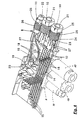
- Fig. 4 shows yet another peculiarity of the connection device, for the modules 8 is to aim for a low overall height.
- the introduction of the electrical leads 21 and the optical fiber cable 22 is carried out by screw caps 25, by means of which the lines 21, 22 are sealed in the usual manner and clamped relieved of strain.
- the modules For screwing the ringkappen 25, the modules have 8 loban arrangements 23, which are provided with an internal thread 24. Accordingly, the screw caps 25 have an external thread 26. This threading is unusual for the purpose mentioned, because in known designs, the screw caps have internal threads, accordingly, the associated housing lugs are equipped with an external thread.
Landscapes
- Physics & Mathematics (AREA)
- General Physics & Mathematics (AREA)
- Optics & Photonics (AREA)
- Connector Housings Or Holding Contact Members (AREA)
- Coupling Device And Connection With Printed Circuit (AREA)
- Optical Couplings Of Light Guides (AREA)
- Screw Conveyors (AREA)
- Mutual Connection Of Rods And Tubes (AREA)
- Mechanical Coupling Of Light Guides (AREA)
Claims (8)
- Dispositif de raccordement pour plusieurs conducteurs électriques (21) et / ou de guides d'ondes optiques (22), en particulier pour un système de bus, avec un boîtier (1) dont la forme de base est rectangulaire ou carrée, et des raccords à fiches (10, 11) y rattachables, qui sont disposés sur l'un des côtés ou sur des côtés opposés du boîtier (1) et sont reliés, à l'intérieur du boîtier, à des éléments constitutifs électriques, électroniques ou photoélectriques au moyen de contacts électriques correspondants (12 - 15) respectivement de jonctions optiques (19, 20),
caractérisé en ce que
la direction d'insertion des raccords à fiches (10, 11) est prévue dans la direction longitudinale et dans la direction transversale du boîtier (1), que les contre-contacts électriques (14), côté boîtier, et / ou le système d'émission et de réception optique (20), côté boîtier, sont disposés le long d'un plan diagonal du boîtier (1) situé sous un angle de 45° par rapport à la direction d'insertion, que les raccords à fiches (10, 11) se trouvent à au moins un module (8) et que leurs contacts (12) et / ou leurs extrémités frontales, émettrices et réceptrices de guides d'ondes optiques (19) sont également disposées dans la direction d'un plan diagonal formant un angle de 45° par rapport à leur direction d'insertion, le module (8) avec les raccords à fiches (10, 11) pouvant être déplacé de 90° sur angle, par rapport à la direction d'insertion, sur le boîtier (1), et la mise en contact électrique et optique ayant lieu, après le déplacement, toujours aux mêmes points de contact dans une position du module (8) pivotée de 180° autour d'un axe, parallèlement à la direction d'insertion. - Dispositif de raccordement selon la revendication 1,
caractérisé en ce que
le module (8) et le boîtier (1) présentent, en position de contact, des surfaces de butée (6, 9) adjacentes qui s'étendent suivant un angle de 45° par rapport à la direction d'insertion des raccords à fiches (10, 11). - Dispositif de raccordement selon l'une des revendications 1 et 2,
caractérisé en ce que
le boîtier (1) est posé sur une plaque de support (5), un ou plusieurs modules étant maintenus entre celle-ci et le boîtier (1). - Dispositif de raccordement selon la revendication 3,
caractérisé en ce que
le boîtier (1) possède un socle inférieur (4) en forme de prisme, avec des surfaces qui, s'étendant dans les plans ou parallèlement aux plans diagonaux du boîtier (1), servent de surfaces de butée (6) pour les modules (8), la plaque de support (5) présentant, sur sa face supérieure, un contour de réception (7) adapté à la surface de base de ce socle (4). - Dispositif de raccordement selon l'une des revendications 1 à 4,
caractérisé en ce que
les raccords à fiches (10) des contacts électriques (12) ont des extrémités fourchues, ouvertes (13) dans la direction d'insertion et que les contre-contacts (14), sur ou dans le boîtier (1), possèdent des lames de contact (15) dégagées, qui sont disposées chacune parallèlement à l'un des côtés du boîtier, et peuvent être agrippées, de leur côté frontal (16) ou de leur côté longitudinal (17), par les extrémités fourchues (13) des contacts (12). - Dispositif de raccordement selon la revendication 5,
caractérisé en ce que
les contacts (12) d'un raccord à fiches (10) ou ceux de deux ou de plusieurs raccords à fiches (10) d'un module (8) sont disposés en harpe, parallèlement, les uns à côté des autres, dans un plan, avec des longueurs étagées, et que, de manière appropriée, les contre-contacts (14) sont disposés, sur ou dans le boîtier (1), avec des longueurs étagées à l'inverse, en harpe, parallèlement, les uns à côté des autres, les contacts (12) et les contre-contacts (14) étant agencés selon une disposition imbriquée, dans des plans parallèles, différents, et les lames de contact (15) des contre-contacts (14) étant coudées dans le plan des contacts (12), respectivement des extrémités fourchues (13) de ceux-ci. - Dispositif de raccordement selon l'une des revendications 1 à 6,
caractérisé en ce que,
pour la transmission de la lumière, les raccords à fiches (11) possèdent au moins un guide d'onde optique (18) qui fait face dans la même position, avec son extrémité frontale émettrice, respectivement réceptrice (19), suivant un angle de 45 degrés par rapport à la direction d'insertion, aussi bien dans une première position de contact que dans une deuxième position de contact inversée, à un système de réception respectivement d'émission (20) installé dans ou sur le boîtier (1) en formant un angle de 45 degrés correspondant. - Dispositif de raccordement selon l'une des revendications 2a 7,
caractérisé en ce que
les raccords à fiches (10, 11) ou le module (8) au moins prévu présentent, sur le côté opposé au boîtier (1), des organes filetés (23) à filet intérieur (24) accueillant des capuchons (25) à filet extérieur (26), pour le passage et le serrage des conducteurs.
Applications Claiming Priority (2)
| Application Number | Priority Date | Filing Date | Title |
|---|---|---|---|
| DE29717271U DE29717271U1 (de) | 1997-09-26 | 1997-09-26 | Anschlußvorrichtung mit Steckanschlüssen |
| DE29717271U | 1997-09-26 |
Publications (3)
| Publication Number | Publication Date |
|---|---|
| EP0905830A2 EP0905830A2 (fr) | 1999-03-31 |
| EP0905830A3 EP0905830A3 (fr) | 1999-12-22 |
| EP0905830B1 true EP0905830B1 (fr) | 2006-05-03 |
Family
ID=8046523
Family Applications (1)
| Application Number | Title | Priority Date | Filing Date |
|---|---|---|---|
| EP98117823A Expired - Lifetime EP0905830B1 (fr) | 1997-09-26 | 1998-09-19 | Dispositif de raccordement avec des raccordements à fiches |
Country Status (3)
| Country | Link |
|---|---|
| EP (1) | EP0905830B1 (fr) |
| AT (1) | ATE325449T1 (fr) |
| DE (3) | DE29717271U1 (fr) |
Families Citing this family (3)
| Publication number | Priority date | Publication date | Assignee | Title |
|---|---|---|---|---|
| DE10139202B4 (de) * | 2001-08-16 | 2007-01-11 | Phoenix Contact Gmbh & Co. Kg | Elektrischer Verteiler |
| DE102008019763B4 (de) | 2008-04-18 | 2019-02-21 | Phoenix Contact Gmbh & Co. Kg | Baueinheit mit einer Befestigungsvorrichtung zur lösbaren rastenden Halterung eines elektrischen Verteilers |
| CN106025732B (zh) * | 2016-04-01 | 2018-02-09 | 刘洋宏 | 带12v电源指示灯4路总线接线排 |
Family Cites Families (7)
| Publication number | Priority date | Publication date | Assignee | Title |
|---|---|---|---|---|
| US4744775A (en) * | 1987-02-12 | 1988-05-17 | Amp Incorporated | Electrical tap connector assembly |
| DE8711780U1 (fr) * | 1987-08-31 | 1987-11-05 | Manfred Fladung Gmbh, 8752 Moembris, De | |
| JPH0371581A (ja) * | 1989-08-09 | 1991-03-27 | Hitachi Ltd | 光電複合分岐コネクタ |
| JPH0423622A (ja) * | 1990-05-18 | 1992-01-28 | Nec Corp | 光海底ケーブルの給電方法 |
| US5285511A (en) * | 1993-01-04 | 1994-02-08 | At&T Laboratories | Optoelectronic cable connector |
| DE4408029C1 (de) * | 1994-03-10 | 1995-08-31 | Amphenol Tuchel Elect | Verteiler-Gehäuse für einen Bus-Verteiler |
| DE19643072A1 (de) * | 1996-10-18 | 1998-04-23 | Alsthom Cge Alcatel | Optoelektronisches Bauelement |
-
1997
- 1997-09-26 DE DE29717271U patent/DE29717271U1/de not_active Expired - Lifetime
-
1998
- 1998-09-18 DE DE29816737U patent/DE29816737U1/de not_active Expired - Lifetime
- 1998-09-19 AT AT98117823T patent/ATE325449T1/de active
- 1998-09-19 EP EP98117823A patent/EP0905830B1/fr not_active Expired - Lifetime
- 1998-09-19 DE DE59813525T patent/DE59813525D1/de not_active Expired - Lifetime
Also Published As
| Publication number | Publication date |
|---|---|
| DE29816737U1 (de) | 1998-11-12 |
| EP0905830A2 (fr) | 1999-03-31 |
| EP0905830A3 (fr) | 1999-12-22 |
| DE59813525D1 (de) | 2006-06-08 |
| ATE325449T1 (de) | 2006-06-15 |
| DE29717271U1 (de) | 1997-11-06 |
Similar Documents
| Publication | Publication Date | Title |
|---|---|---|
| EP1783521B1 (fr) | Connecteur et systeme de connexion RJ-45 | |
| DE60123984T2 (de) | Modulares verbindungssystem für ethernet-anwendungen im industriellen sektor | |
| DE4402002B4 (de) | E/A-Module/ für einen Datenbus | |
| EP1504297B1 (fr) | Connecteur enfichable hybride | |
| EP0112476B1 (fr) | Ensemble d'installation électrique | |
| DE60131723T2 (de) | Schwimmend montierte Verbinderanordnung | |
| DE102008058090B4 (de) | Ein-/Ausgabemodul für ein Automatisierungsgerät | |
| EP0762165A2 (fr) | Connecteur hybride avec des connexions de conducteurs électriques et optiques | |
| CH693657A5 (de) | Hybrider Datenstecker. | |
| DE19652551C1 (de) | Hochpoliger geschirmter Kabelstecker | |
| EP0905830B1 (fr) | Dispositif de raccordement avec des raccordements à fiches | |
| EP0368074B1 (fr) | Dispositif de fixation d'un connecteur dans l'ouverture d'un panneau, sur un support ou similaire | |
| DE60220234T2 (de) | Optisches Stecker-System | |
| DE4400484C3 (de) | Niederspannungsschaltgerät | |
| DE19743972A1 (de) | Elektronisches Ein-/Ausgabemodul | |
| DE10139202B4 (de) | Elektrischer Verteiler | |
| EP0753906A2 (fr) | Connecteur électrique à fiche | |
| EP1317684A2 (fr) | Douille de guide d'ondes optiques, fiche de guide d'ondes optiques et agencement de douille de guide d'ondes optiques | |
| EP0057255B1 (fr) | Connecteur de ligne pour ensembles plats | |
| DE4401621C2 (de) | Kompakte, mehrpolige Steckverbindung | |
| DE102017220445A1 (de) | Leitfähiges Modul und Batteriepack | |
| EP0821458A2 (fr) | Dispositif de répartition de lignes | |
| DE3621223A1 (de) | Anschlussleiste fuer elektrische leitungen | |
| EP3769372A1 (fr) | Support de contact modulaire pour connecteur enfichable industriel | |
| DE19733174A1 (de) | Steckverbinderanordnung für Lichtwellenleiter |
Legal Events
| Date | Code | Title | Description |
|---|---|---|---|
| PUAI | Public reference made under article 153(3) epc to a published international application that has entered the european phase |
Free format text: ORIGINAL CODE: 0009012 |
|
| AK | Designated contracting states |
Kind code of ref document: A2 Designated state(s): AT BE CH DE FR GB IT LI NL |
|
| AX | Request for extension of the european patent |
Free format text: AL;LT;LV;MK;RO;SI |
|
| RIN1 | Information on inventor provided before grant (corrected) |
Inventor name: OSTER, VIKTOR DIPL.-ING. Inventor name: HANNIBAL, FRANK DIPL.-ING. Inventor name: METZGER,ANDREAS Inventor name: BRAND,JUERGEN,DIPL.-ING. Inventor name: GREWE,HARALD,DIPL.-ING. Inventor name: BERG,ROLAND Inventor name: FUERHOFF,ACHIM,DIPL.-ING. Inventor name: BEHR,THORSTEN,DIPL.-ING. |
|
| K1C1 | Correction of patent application (title page) published |
Effective date: 19990331 |
|
| RIN1 | Information on inventor provided before grant (corrected) |
Inventor name: OSTER,VIKTOR,DIPL.-ING. Inventor name: HANNIBAL,FRANK,DIPL.-ING. Inventor name: METZGER,ANDREAS Inventor name: BRAND,JUERGEN,DIPL.-ING. Inventor name: GREWE,HARALD,DIPL.-ING. Inventor name: BERG,ROLAND Inventor name: FUERHOFF,ACHIM,DIPL.-ING. Inventor name: BEHR,THORSTEN,DIPL.-ING. |
|
| PUAL | Search report despatched |
Free format text: ORIGINAL CODE: 0009013 |
|
| RIC1 | Information provided on ipc code assigned before grant |
Free format text: 6H 01R 31/06 A, 6G 02B 6/38 B, 6H 01R 9/24 B, 6H 01R 13/59 B, 6G 02B 6/42 B |
|
| AK | Designated contracting states |
Kind code of ref document: A3 Designated state(s): AT BE CH CY DE DK ES FI FR GB GR IE IT LI LU MC NL PT SE |
|
| AX | Request for extension of the european patent |
Free format text: AL;LT;LV;MK;RO;SI |
|
| 17P | Request for examination filed |
Effective date: 20000113 |
|
| RIN1 | Information on inventor provided before grant (corrected) |
Inventor name: OSTER,VIKTOR,DIPL.-ING. Inventor name: HANNIBAL,FRANK,DIPL.-ING. Inventor name: METZGER,ANDREAS Inventor name: BRAND,JUERGEN,DIPL.-ING. Inventor name: GREWE,HARALD,DIPL.-ING. Inventor name: BERG,ROLAND Inventor name: FUERHOFF,ACHIM,DIPL.-ING. Inventor name: BEHR,THORSTEN,DIPL.-ING. |
|
| AKX | Designation fees paid |
Free format text: AT BE CH DE FR GB IT LI NL |
|
| RAP1 | Party data changed (applicant data changed or rights of an application transferred) |
Owner name: PHOENIX CONTACT GMBH & CO. KG |
|
| 17Q | First examination report despatched |
Effective date: 20030402 |
|
| GRAP | Despatch of communication of intention to grant a patent |
Free format text: ORIGINAL CODE: EPIDOSNIGR1 |
|
| GRAS | Grant fee paid |
Free format text: ORIGINAL CODE: EPIDOSNIGR3 |
|
| GRAA | (expected) grant |
Free format text: ORIGINAL CODE: 0009210 |
|
| AK | Designated contracting states |
Kind code of ref document: B1 Designated state(s): AT BE CH DE FR GB IT LI NL |
|
| REG | Reference to a national code |
Ref country code: GB Ref legal event code: FG4D Free format text: NOT ENGLISH |
|
| REG | Reference to a national code |
Ref country code: CH Ref legal event code: EP |
|
| REF | Corresponds to: |
Ref document number: 59813525 Country of ref document: DE Date of ref document: 20060608 Kind code of ref document: P |
|
| GBT | Gb: translation of ep patent filed (gb section 77(6)(a)/1977) |
Effective date: 20060518 |
|
| REG | Reference to a national code |
Ref country code: CH Ref legal event code: NV Representative=s name: SCHMAUDER & PARTNER AG PATENTANWALTSBUERO |
|
| ET | Fr: translation filed | ||
| PLBE | No opposition filed within time limit |
Free format text: ORIGINAL CODE: 0009261 |
|
| STAA | Information on the status of an ep patent application or granted ep patent |
Free format text: STATUS: NO OPPOSITION FILED WITHIN TIME LIMIT |
|
| 26N | No opposition filed |
Effective date: 20070206 |
|
| REG | Reference to a national code |
Ref country code: CH Ref legal event code: PCAR Free format text: SCHMAUDER & PARTNER AG PATENT- UND MARKENANWAELTE VSP;ZWAENGIWEG 7;8038 ZUERICH (CH) |
|
| PGFP | Annual fee paid to national office [announced via postgrant information from national office to epo] |
Ref country code: CH Payment date: 20121001 Year of fee payment: 15 |
|
| PGFP | Annual fee paid to national office [announced via postgrant information from national office to epo] |
Ref country code: NL Payment date: 20120917 Year of fee payment: 15 Ref country code: AT Payment date: 20120924 Year of fee payment: 15 |
|
| PGFP | Annual fee paid to national office [announced via postgrant information from national office to epo] |
Ref country code: DE Payment date: 20130819 Year of fee payment: 16 |
|
| PGFP | Annual fee paid to national office [announced via postgrant information from national office to epo] |
Ref country code: GB Payment date: 20130925 Year of fee payment: 16 |
|
| PGFP | Annual fee paid to national office [announced via postgrant information from national office to epo] |
Ref country code: IT Payment date: 20130921 Year of fee payment: 16 |
|
| PGFP | Annual fee paid to national office [announced via postgrant information from national office to epo] |
Ref country code: BE Payment date: 20130925 Year of fee payment: 16 Ref country code: FR Payment date: 20130920 Year of fee payment: 16 |
|
| REG | Reference to a national code |
Ref country code: NL Ref legal event code: V1 Effective date: 20140401 |
|
| REG | Reference to a national code |
Ref country code: CH Ref legal event code: PL |
|
| REG | Reference to a national code |
Ref country code: AT Ref legal event code: MM01 Ref document number: 325449 Country of ref document: AT Kind code of ref document: T Effective date: 20130919 |
|
| PG25 | Lapsed in a contracting state [announced via postgrant information from national office to epo] |
Ref country code: CH Free format text: LAPSE BECAUSE OF NON-PAYMENT OF DUE FEES Effective date: 20130930 Ref country code: LI Free format text: LAPSE BECAUSE OF NON-PAYMENT OF DUE FEES Effective date: 20130930 |
|
| PG25 | Lapsed in a contracting state [announced via postgrant information from national office to epo] |
Ref country code: AT Free format text: LAPSE BECAUSE OF NON-PAYMENT OF DUE FEES Effective date: 20130919 Ref country code: NL Free format text: LAPSE BECAUSE OF NON-PAYMENT OF DUE FEES Effective date: 20140401 |
|
| REG | Reference to a national code |
Ref country code: DE Ref legal event code: R119 Ref document number: 59813525 Country of ref document: DE |
|
| GBPC | Gb: european patent ceased through non-payment of renewal fee |
Effective date: 20140919 |
|
| REG | Reference to a national code |
Ref country code: DE Ref legal event code: R119 Ref document number: 59813525 Country of ref document: DE Effective date: 20150401 |
|
| REG | Reference to a national code |
Ref country code: FR Ref legal event code: ST Effective date: 20150529 |
|
| PG25 | Lapsed in a contracting state [announced via postgrant information from national office to epo] |
Ref country code: BE Free format text: LAPSE BECAUSE OF NON-PAYMENT OF DUE FEES Effective date: 20140930 |
|
| PG25 | Lapsed in a contracting state [announced via postgrant information from national office to epo] |
Ref country code: GB Free format text: LAPSE BECAUSE OF NON-PAYMENT OF DUE FEES Effective date: 20140919 Ref country code: DE Free format text: LAPSE BECAUSE OF NON-PAYMENT OF DUE FEES Effective date: 20150401 |
|
| PG25 | Lapsed in a contracting state [announced via postgrant information from national office to epo] |
Ref country code: IT Free format text: LAPSE BECAUSE OF NON-PAYMENT OF DUE FEES Effective date: 20140919 Ref country code: FR Free format text: LAPSE BECAUSE OF NON-PAYMENT OF DUE FEES Effective date: 20140930 |