EP0821458A2 - Dispositif de répartition de lignes - Google Patents
Dispositif de répartition de lignes Download PDFInfo
- Publication number
- EP0821458A2 EP0821458A2 EP97112114A EP97112114A EP0821458A2 EP 0821458 A2 EP0821458 A2 EP 0821458A2 EP 97112114 A EP97112114 A EP 97112114A EP 97112114 A EP97112114 A EP 97112114A EP 0821458 A2 EP0821458 A2 EP 0821458A2
- Authority
- EP
- European Patent Office
- Prior art keywords
- housing
- distributor according
- line distributor
- conductor strand
- line
- Prior art date
- Legal status (The legal status is an assumption and is not a legal conclusion. Google has not performed a legal analysis and makes no representation as to the accuracy of the status listed.)
- Granted
Links
- 239000004020 conductor Substances 0.000 claims abstract description 46
- 230000003287 optical effect Effects 0.000 claims description 4
- 239000013307 optical fiber Substances 0.000 claims description 2
- 230000005540 biological transmission Effects 0.000 claims 1
- 238000006243 chemical reaction Methods 0.000 claims 1
- 238000006073 displacement reaction Methods 0.000 claims 1
- 230000037431 insertion Effects 0.000 claims 1
- 238000003780 insertion Methods 0.000 claims 1
- 238000009413 insulation Methods 0.000 claims 1
- 230000005405 multipole Effects 0.000 claims 1
- 230000035515 penetration Effects 0.000 claims 1
- 229910000679 solder Inorganic materials 0.000 claims 1
- 230000002950 deficient Effects 0.000 description 1
- 238000001514 detection method Methods 0.000 description 1
Images
Classifications
-
- H—ELECTRICITY
- H01—ELECTRIC ELEMENTS
- H01R—ELECTRICALLY-CONDUCTIVE CONNECTIONS; STRUCTURAL ASSOCIATIONS OF A PLURALITY OF MUTUALLY-INSULATED ELECTRICAL CONNECTING ELEMENTS; COUPLING DEVICES; CURRENT COLLECTORS
- H01R31/00—Coupling parts supported only by co-operation with counterpart
- H01R31/02—Intermediate parts for distributing energy to two or more circuits in parallel, e.g. splitter
-
- H—ELECTRICITY
- H01—ELECTRIC ELEMENTS
- H01R—ELECTRICALLY-CONDUCTIVE CONNECTIONS; STRUCTURAL ASSOCIATIONS OF A PLURALITY OF MUTUALLY-INSULATED ELECTRICAL CONNECTING ELEMENTS; COUPLING DEVICES; CURRENT COLLECTORS
- H01R25/00—Coupling parts adapted for simultaneous co-operation with two or more identical counterparts, e.g. for distributing energy to two or more circuits
- H01R25/16—Rails or bus-bars provided with a plurality of discrete connecting locations for counterparts
-
- H—ELECTRICITY
- H01—ELECTRIC ELEMENTS
- H01R—ELECTRICALLY-CONDUCTIVE CONNECTIONS; STRUCTURAL ASSOCIATIONS OF A PLURALITY OF MUTUALLY-INSULATED ELECTRICAL CONNECTING ELEMENTS; COUPLING DEVICES; CURRENT COLLECTORS
- H01R4/00—Electrically-conductive connections between two or more conductive members in direct contact, i.e. touching one another; Means for effecting or maintaining such contact; Electrically-conductive connections having two or more spaced connecting locations for conductors and using contact members penetrating insulation
- H01R4/28—Clamped connections, spring connections
- H01R4/48—Clamped connections, spring connections utilising a spring, clip, or other resilient member
- H01R4/4809—Clamped connections, spring connections utilising a spring, clip, or other resilient member using a leaf spring to bias the conductor toward the busbar
- H01R4/48185—Clamped connections, spring connections utilising a spring, clip, or other resilient member using a leaf spring to bias the conductor toward the busbar adapted for axial insertion of a wire end
Definitions
- the invention relates to a line splitter for branching a conductor strand.
- Line distributors of this type are used for connecting electrical consumers in networked electrical systems, a conductor line being provided to supply the consumers with the required electrical power and, viewed electrically, the consumers are connected in parallel to the line line.
- the control of the consumers ie the selection of which of the consumers should be switched on, is made via a signal bus system. It is known to guide the conductor strand over consumer junction boxes, the conductor strand then being practically looped through these junction boxes. In the event of a consumer failure and the necessary replacement, the lines must be disconnected, with subsequent consumers then being at least temporarily disconnected from the wiring harness.
- the replacement of a defective consumer or the connection of a new consumer is also relatively complex, and wiring and connection errors can easily occur.
- the invention has for its object to a line splitter create the connection of new consumers or the replacement of one Simplified.
- the line distributor has a housing has through which the conductor strand with the interposition of an im essential T-shaped wiring structure is looped through that on a Side of the housing a plug connection is provided, and that the Conductor of the conductor strand connected to one another via the wiring structure and the contacts of the plug connection with the conductors of the conductor strand are connected.
- the advantages achieved by the invention are in particular that the conductor strand is looped through the line distributor without interruption is and that the new connection or the replacement of a consumer via a simple plug-in connection, the conductor strand does not have to be interrupted.
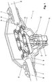
- the 1 consists essentially of a T-shaped housing 1, which has an upper crossbar 2 and a base 3.
- a plug connection 5 provided with plug contacts 4 is arranged at the base.
- This plug connection is designed as a plug connection known per se, so that commercially available plug connectors can be plugged onto it.
- PG screw connections 7 are provided on both sides 6 of the crossbar, through which the ends of a conductor strand 8 are inserted into the housing.
- the individual conductors 9 of the conductor strand or cable are connected to one another via busbars 10.
- the connections of the conductors to the busbars are preferably designed as cage tension springs 11.
- the busbars also have a molded part 12, each of which has an associated contact 4 of the plug connection and the end of which is connected to the contact.
- the wiring structure within the housing 1 is essentially T-shaped. Although a T-shaped housing is therefore preferably also provided, this is not absolutely necessary, however, the housing may also have a different geometric shape.
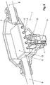
- an electronic circuit 13 is provided in the housing 1, via which the conductors 9 of the conductor strand are guided and the conductors are directly connected.
- switching means (not shown in detail here) are provided, by means of which the consumer connected to the plug connection can be switched.
- the switching means are controlled via separate control lines or via control lines which are provided in addition to the conductors 9 in the cable of the conductor strand.
- the electronic circuit can also with indicator lights 14, such as. B. LEDs, and buttons or switches 15 are provided, which are visible or accessible from the outside of the housing. The light indicators are used to indicate the operating status of the connected consumer and the buttons or switches can be used to reset or influence the logic of the electronic circuit in the event of a fault.
- the signals for controlling the Switching means on the conductor 9 of the conductor strand transmitting the electrical power are modulated. It is then in the electronic circuit logic for detection and decoding provided the control signals recognizes and causes the corresponding control of the switching means.
- control signals as optical signals via optical fibers in the housing 1 are guided.
- optical signals into electrical Signals to control the switching means is then a corresponding one Device provided in the electronic circuit 13.
- the housing 1 can also be designed to be EMC-tight on the one hand, the switching means are influenced by external interference signals avoid and on the other hand to emit interference signals when To prevent switching of the switching means out of the housing.
Landscapes
- Details Of Connecting Devices For Male And Female Coupling (AREA)
- Cable Accessories (AREA)
- Coupling Device And Connection With Printed Circuit (AREA)
Applications Claiming Priority (2)
| Application Number | Priority Date | Filing Date | Title |
|---|---|---|---|
| DE19630202 | 1996-07-26 | ||
| DE19630202A DE19630202C2 (de) | 1996-07-26 | 1996-07-26 | Leitungsverzweiger |
Publications (3)
| Publication Number | Publication Date |
|---|---|
| EP0821458A2 true EP0821458A2 (fr) | 1998-01-28 |
| EP0821458A3 EP0821458A3 (fr) | 1999-03-17 |
| EP0821458B1 EP0821458B1 (fr) | 2004-04-07 |
Family
ID=7800929
Family Applications (1)
| Application Number | Title | Priority Date | Filing Date |
|---|---|---|---|
| EP97112114A Revoked EP0821458B1 (fr) | 1996-07-26 | 1997-07-16 | Dispositif de répartition de lignes |
Country Status (3)
| Country | Link |
|---|---|
| US (1) | US5937119A (fr) |
| EP (1) | EP0821458B1 (fr) |
| DE (2) | DE19630202C2 (fr) |
Cited By (2)
| Publication number | Priority date | Publication date | Assignee | Title |
|---|---|---|---|---|
| WO2009082600A1 (fr) * | 2007-12-20 | 2009-07-02 | 3M Innovative Properties Company | Connecteur électrique |
| US7670197B2 (en) | 2007-12-20 | 2010-03-02 | 3M Innovative Properties Company | Electrical splice connector |
Families Citing this family (5)
| Publication number | Priority date | Publication date | Assignee | Title |
|---|---|---|---|---|
| DE19906465C2 (de) * | 1999-02-16 | 2001-02-15 | Krone Gmbh | Stromverteilerdose |
| FR2815180B1 (fr) * | 2000-10-10 | 2002-12-20 | Schneider Electric Ind Sa | Connecteur a plots amovibles pour canalisation electrique |
| FR2815179B1 (fr) * | 2000-10-10 | 2002-12-20 | Schneider Electric Ind Sa | Connecteur a plots amovibles pour canalisation electrique |
| DE202004014562U1 (de) * | 2004-09-16 | 2004-11-18 | Schmitt, Fred R. | Gehäuse für Steckverbinder |
| TWI740050B (zh) | 2018-06-01 | 2021-09-21 | 日商島野股份有限公司 | 用於人力交通工具之電纜線總成 |
Citations (9)
| Publication number | Priority date | Publication date | Assignee | Title |
|---|---|---|---|---|
| US4392701A (en) * | 1980-07-16 | 1983-07-12 | Amp Incorporated | Tap connector assembly |
| US4405187A (en) * | 1980-06-06 | 1983-09-20 | Krone Gmbh | Connector assembly for PCM cables |
| DE3412116A1 (de) * | 1984-03-31 | 1985-10-10 | U.I. Lapp Kg, 7000 Stuttgart | Vorrichtung zum nachruesten von kabel-, leitungs- und schlauchverschraubungen mit einem biegeschutz |
| US4571018A (en) * | 1984-05-15 | 1986-02-18 | Houston Geophysical Products, Inc. | Seismic marsh T-coupler with removable polarized connectors |
| US4767168A (en) * | 1986-12-24 | 1988-08-30 | Prestolite Wire Corporation | Hybrid connector cable system |
| US4857016A (en) * | 1983-03-30 | 1989-08-15 | Butler Manufacturing Company | Components for flexible wiring systems |
| US5293298A (en) * | 1991-10-16 | 1994-03-08 | International Business Machines Corporation | Electrical connector |
| DE19517153A1 (de) * | 1994-05-10 | 1995-11-16 | Miguel Francisco Jo Traspuesto | Mehrfach-Stromanschlußvorrichtung für Elektrogeräte |
| DE29501970U1 (de) * | 1995-02-07 | 1996-06-05 | Lumberg Karl Gmbh & Co | Anschlußvorrichtung zur wahlfreien Herstellung eines wiederverwendbaren elektrischen Anschlusses bzw. Abgriffs an mehradrigen elektrischen Leitungen |
Family Cites Families (5)
| Publication number | Priority date | Publication date | Assignee | Title |
|---|---|---|---|---|
| FR2356171A1 (fr) * | 1976-01-27 | 1978-01-20 | Thomson Csf | Derivation opto-electrique pour liaisons par faisceaux de fibres optiques |
| US4234760A (en) * | 1978-12-18 | 1980-11-18 | Amp Incorporated | Covering for T-tap terminals |
| DE9217344U1 (fr) * | 1992-12-18 | 1993-02-18 | Mannesmann Kienzle Gmbh, 7730 Villingen-Schwenningen, De | |
| US5757994A (en) * | 1995-09-22 | 1998-05-26 | Boeing North American, Inc. | Three-part optical coupler |
| US5666448A (en) * | 1995-09-22 | 1997-09-09 | Rockwell International Corporation | Variable splitting optical coupler |
-
1996
- 1996-07-26 DE DE19630202A patent/DE19630202C2/de not_active Expired - Fee Related
-
1997
- 1997-07-09 US US08/890,475 patent/US5937119A/en not_active Expired - Fee Related
- 1997-07-16 DE DE59711489T patent/DE59711489D1/de not_active Revoked
- 1997-07-16 EP EP97112114A patent/EP0821458B1/fr not_active Revoked
Patent Citations (9)
| Publication number | Priority date | Publication date | Assignee | Title |
|---|---|---|---|---|
| US4405187A (en) * | 1980-06-06 | 1983-09-20 | Krone Gmbh | Connector assembly for PCM cables |
| US4392701A (en) * | 1980-07-16 | 1983-07-12 | Amp Incorporated | Tap connector assembly |
| US4857016A (en) * | 1983-03-30 | 1989-08-15 | Butler Manufacturing Company | Components for flexible wiring systems |
| DE3412116A1 (de) * | 1984-03-31 | 1985-10-10 | U.I. Lapp Kg, 7000 Stuttgart | Vorrichtung zum nachruesten von kabel-, leitungs- und schlauchverschraubungen mit einem biegeschutz |
| US4571018A (en) * | 1984-05-15 | 1986-02-18 | Houston Geophysical Products, Inc. | Seismic marsh T-coupler with removable polarized connectors |
| US4767168A (en) * | 1986-12-24 | 1988-08-30 | Prestolite Wire Corporation | Hybrid connector cable system |
| US5293298A (en) * | 1991-10-16 | 1994-03-08 | International Business Machines Corporation | Electrical connector |
| DE19517153A1 (de) * | 1994-05-10 | 1995-11-16 | Miguel Francisco Jo Traspuesto | Mehrfach-Stromanschlußvorrichtung für Elektrogeräte |
| DE29501970U1 (de) * | 1995-02-07 | 1996-06-05 | Lumberg Karl Gmbh & Co | Anschlußvorrichtung zur wahlfreien Herstellung eines wiederverwendbaren elektrischen Anschlusses bzw. Abgriffs an mehradrigen elektrischen Leitungen |
Cited By (2)
| Publication number | Priority date | Publication date | Assignee | Title |
|---|---|---|---|---|
| WO2009082600A1 (fr) * | 2007-12-20 | 2009-07-02 | 3M Innovative Properties Company | Connecteur électrique |
| US7670197B2 (en) | 2007-12-20 | 2010-03-02 | 3M Innovative Properties Company | Electrical splice connector |
Also Published As
| Publication number | Publication date |
|---|---|
| US5937119A (en) | 1999-08-10 |
| EP0821458B1 (fr) | 2004-04-07 |
| DE59711489D1 (de) | 2004-05-13 |
| DE19630202C2 (de) | 1999-09-23 |
| DE19630202A1 (de) | 1998-01-29 |
| EP0821458A3 (fr) | 1999-03-17 |
Similar Documents
| Publication | Publication Date | Title |
|---|---|---|
| DE112011101265B4 (de) | Sicherungseinheit | |
| DE102008058090B4 (de) | Ein-/Ausgabemodul für ein Automatisierungsgerät | |
| DE4440102C1 (de) | Modulare Steuerungsanlage mit integriertem Feldbusanschluß | |
| DE102017219214B4 (de) | Verzweigungsaufbau und kabelbaum | |
| EP2710619B1 (fr) | Câblage de système pour ensemble multi-relais | |
| EP3073176B1 (fr) | Systeme de raccordement electrique pour lampes | |
| EP0821458B1 (fr) | Dispositif de répartition de lignes | |
| EP3631922B1 (fr) | Tableau de distribution | |
| EP2105033B1 (fr) | Dispositif de distribution destine aux domaines de la communication et de l'informatique | |
| DE69819983T2 (de) | Stromverteilungssystem | |
| EP0759651A2 (fr) | Boîtier modulaire pour insertion dans des boîtiers encastrables | |
| DE19743972A1 (de) | Elektronisches Ein-/Ausgabemodul | |
| DE3537432C2 (fr) | ||
| EP0984169B1 (fr) | Arrangement de soupapes avec au moins une unité composée de plusieurs soupapes à actionnement électrique | |
| DE102008020348A1 (de) | Stromverteilung für Fahrzeuge, insbesondere Luftfahrzeuge | |
| EP0536442B1 (fr) | Barrette à bornes | |
| EP1169762B1 (fr) | Systeme de bus a ligne de bus de donnees et a ligne de bus d'energie | |
| DE102012010244A1 (de) | Elektrische Anschlussklemme | |
| DE102004036163B4 (de) | Steuereinrichtung für elektrohydraulische Ausbausteuerungen | |
| DE102007046433A1 (de) | Verteilereinrichtung | |
| DE8212541U1 (de) | Interne Anschlußleitung | |
| DE3302373A1 (de) | Schaltanlagen-reihenklemme | |
| DE10041438B4 (de) | Anordnung zum Kuppeln einer Mehrzahl erster Lichtwellenleiter-Fasern mit einer Mehrzahl zweiter Lichtwellenleiter-Fasern | |
| DE10261927B4 (de) | Flachkabel-System | |
| DE102019006330A1 (de) | Elektrische Reihenklemme |
Legal Events
| Date | Code | Title | Description |
|---|---|---|---|
| PUAI | Public reference made under article 153(3) epc to a published international application that has entered the european phase |
Free format text: ORIGINAL CODE: 0009012 |
|
| AK | Designated contracting states |
Kind code of ref document: A2 Designated state(s): DE FR GB IT |
|
| AX | Request for extension of the european patent |
Free format text: AL;LT;LV;RO;SI |
|
| PUAL | Search report despatched |
Free format text: ORIGINAL CODE: 0009013 |
|
| AK | Designated contracting states |
Kind code of ref document: A3 Designated state(s): AT BE CH DE DK ES FI FR GB GR IE IT LI LU MC NL PT SE |
|
| AX | Request for extension of the european patent |
Free format text: AL;LT;LV;RO;SI |
|
| 17P | Request for examination filed |
Effective date: 19990517 |
|
| AKX | Designation fees paid |
Free format text: DE FR GB IT |
|
| 17Q | First examination report despatched |
Effective date: 20021125 |
|
| GRAP | Despatch of communication of intention to grant a patent |
Free format text: ORIGINAL CODE: EPIDOSNIGR1 |
|
| RAP1 | Party data changed (applicant data changed or rights of an application transferred) |
Owner name: HARTING ELECTRIC GMBH & CO. KG |
|
| GRAS | Grant fee paid |
Free format text: ORIGINAL CODE: EPIDOSNIGR3 |
|
| GRAA | (expected) grant |
Free format text: ORIGINAL CODE: 0009210 |
|
| AK | Designated contracting states |
Kind code of ref document: B1 Designated state(s): DE FR GB IT |
|
| REG | Reference to a national code |
Ref country code: GB Ref legal event code: FG4D Free format text: NOT ENGLISH |
|
| REF | Corresponds to: |
Ref document number: 59711489 Country of ref document: DE Date of ref document: 20040513 Kind code of ref document: P |
|
| GBT | Gb: translation of ep patent filed (gb section 77(6)(a)/1977) |
Effective date: 20040615 |
|
| ET | Fr: translation filed | ||
| PLBQ | Unpublished change to opponent data |
Free format text: ORIGINAL CODE: EPIDOS OPPO |
|
| PLBI | Opposition filed |
Free format text: ORIGINAL CODE: 0009260 |
|
| PLAX | Notice of opposition and request to file observation + time limit sent |
Free format text: ORIGINAL CODE: EPIDOSNOBS2 |
|
| 26 | Opposition filed |
Opponent name: PHOENIX CONTACT GMBH & CO. KG Effective date: 20050107 |
|
| PLAX | Notice of opposition and request to file observation + time limit sent |
Free format text: ORIGINAL CODE: EPIDOSNOBS2 |
|
| PLBB | Reply of patent proprietor to notice(s) of opposition received |
Free format text: ORIGINAL CODE: EPIDOSNOBS3 |
|
| PLAY | Examination report in opposition despatched + time limit |
Free format text: ORIGINAL CODE: EPIDOSNORE2 |
|
| PLAH | Information related to despatch of examination report in opposition + time limit modified |
Free format text: ORIGINAL CODE: EPIDOSCORE2 |
|
| PLBC | Reply to examination report in opposition received |
Free format text: ORIGINAL CODE: EPIDOSNORE3 |
|
| PGFP | Annual fee paid to national office [announced via postgrant information from national office to epo] |
Ref country code: DE Payment date: 20070713 Year of fee payment: 11 |
|
| PGFP | Annual fee paid to national office [announced via postgrant information from national office to epo] |
Ref country code: GB Payment date: 20070625 Year of fee payment: 11 |
|
| PGFP | Annual fee paid to national office [announced via postgrant information from national office to epo] |
Ref country code: IT Payment date: 20070721 Year of fee payment: 11 |
|
| RDAF | Communication despatched that patent is revoked |
Free format text: ORIGINAL CODE: EPIDOSNREV1 |
|
| PGFP | Annual fee paid to national office [announced via postgrant information from national office to epo] |
Ref country code: FR Payment date: 20070718 Year of fee payment: 11 |
|
| RDAG | Patent revoked |
Free format text: ORIGINAL CODE: 0009271 |
|
| STAA | Information on the status of an ep patent application or granted ep patent |
Free format text: STATUS: PATENT REVOKED |
|
| 27W | Patent revoked |
Effective date: 20071210 |
|
| GBPR | Gb: patent revoked under art. 102 of the ep convention designating the uk as contracting state |
Effective date: 20071210 |
|
| PLAB | Opposition data, opponent's data or that of the opponent's representative modified |
Free format text: ORIGINAL CODE: 0009299OPPO |