EP0904920A2 - Verfahren zur Herstellung eines Kunststofformteils mit Einsatz und so hergestelltes Formteil - Google Patents
Verfahren zur Herstellung eines Kunststofformteils mit Einsatz und so hergestelltes Formteil Download PDFInfo
- Publication number
- EP0904920A2 EP0904920A2 EP98402306A EP98402306A EP0904920A2 EP 0904920 A2 EP0904920 A2 EP 0904920A2 EP 98402306 A EP98402306 A EP 98402306A EP 98402306 A EP98402306 A EP 98402306A EP 0904920 A2 EP0904920 A2 EP 0904920A2
- Authority
- EP
- European Patent Office
- Prior art keywords
- resin
- insert
- molded product
- metallic
- cavity
- Prior art date
- Legal status (The legal status is an assumption and is not a legal conclusion. Google has not performed a legal analysis and makes no representation as to the accuracy of the status listed.)
- Withdrawn
Links
Images


Classifications
-
- B—PERFORMING OPERATIONS; TRANSPORTING
- B29—WORKING OF PLASTICS; WORKING OF SUBSTANCES IN A PLASTIC STATE IN GENERAL
- B29C—SHAPING OR JOINING OF PLASTICS; SHAPING OF MATERIAL IN A PLASTIC STATE, NOT OTHERWISE PROVIDED FOR; AFTER-TREATMENT OF THE SHAPED PRODUCTS, e.g. REPAIRING
- B29C45/00—Injection moulding, i.e. forcing the required volume of moulding material through a nozzle into a closed mould; Apparatus therefor
- B29C45/14—Injection moulding, i.e. forcing the required volume of moulding material through a nozzle into a closed mould; Apparatus therefor incorporating preformed parts or layers, e.g. injection moulding around inserts or for coating articles
- B29C45/14065—Positioning or centering articles in the mould
-
- B—PERFORMING OPERATIONS; TRANSPORTING
- B29—WORKING OF PLASTICS; WORKING OF SUBSTANCES IN A PLASTIC STATE IN GENERAL
- B29C—SHAPING OR JOINING OF PLASTICS; SHAPING OF MATERIAL IN A PLASTIC STATE, NOT OTHERWISE PROVIDED FOR; AFTER-TREATMENT OF THE SHAPED PRODUCTS, e.g. REPAIRING
- B29C45/00—Injection moulding, i.e. forcing the required volume of moulding material through a nozzle into a closed mould; Apparatus therefor
- B29C45/14—Injection moulding, i.e. forcing the required volume of moulding material through a nozzle into a closed mould; Apparatus therefor incorporating preformed parts or layers, e.g. injection moulding around inserts or for coating articles
- B29C45/14639—Injection moulding, i.e. forcing the required volume of moulding material through a nozzle into a closed mould; Apparatus therefor incorporating preformed parts or layers, e.g. injection moulding around inserts or for coating articles for obtaining an insulating effect, e.g. for electrical components
-
- H—ELECTRICITY
- H01—ELECTRIC ELEMENTS
- H01R—ELECTRICALLY-CONDUCTIVE CONNECTIONS; STRUCTURAL ASSOCIATIONS OF A PLURALITY OF MUTUALLY-INSULATED ELECTRICAL CONNECTING ELEMENTS; COUPLING DEVICES; CURRENT COLLECTORS
- H01R43/00—Apparatus or processes specially adapted for manufacturing, assembling, maintaining, or repairing of line connectors or current collectors or for joining electric conductors
- H01R43/16—Apparatus or processes specially adapted for manufacturing, assembling, maintaining, or repairing of line connectors or current collectors or for joining electric conductors for manufacturing contact members, e.g. by punching and by bending
-
- B—PERFORMING OPERATIONS; TRANSPORTING
- B29—WORKING OF PLASTICS; WORKING OF SUBSTANCES IN A PLASTIC STATE IN GENERAL
- B29C—SHAPING OR JOINING OF PLASTICS; SHAPING OF MATERIAL IN A PLASTIC STATE, NOT OTHERWISE PROVIDED FOR; AFTER-TREATMENT OF THE SHAPED PRODUCTS, e.g. REPAIRING
- B29C45/00—Injection moulding, i.e. forcing the required volume of moulding material through a nozzle into a closed mould; Apparatus therefor
- B29C45/14—Injection moulding, i.e. forcing the required volume of moulding material through a nozzle into a closed mould; Apparatus therefor incorporating preformed parts or layers, e.g. injection moulding around inserts or for coating articles
- B29C2045/1486—Details, accessories and auxiliary operations
- B29C2045/14991—Submerged burrs, e.g. using protruding mould parts forming a cavity in which the burr on the insert is formed for preventing surface defects
-
- B—PERFORMING OPERATIONS; TRANSPORTING
- B29—WORKING OF PLASTICS; WORKING OF SUBSTANCES IN A PLASTIC STATE IN GENERAL
- B29K—INDEXING SCHEME ASSOCIATED WITH SUBCLASSES B29B, B29C OR B29D, RELATING TO MOULDING MATERIALS OR TO MATERIALS FOR MOULDS, REINFORCEMENTS, FILLERS OR PREFORMED PARTS, e.g. INSERTS
- B29K2705/00—Use of metals, their alloys or their compounds, for preformed parts, e.g. for inserts
-
- H—ELECTRICITY
- H01—ELECTRIC ELEMENTS
- H01R—ELECTRICALLY-CONDUCTIVE CONNECTIONS; STRUCTURAL ASSOCIATIONS OF A PLURALITY OF MUTUALLY-INSULATED ELECTRICAL CONNECTING ELEMENTS; COUPLING DEVICES; CURRENT COLLECTORS
- H01R9/00—Structural associations of a plurality of mutually-insulated electrical connecting elements, e.g. terminal strips or terminal blocks; Terminals or binding posts mounted upon a base or in a case; Bases therefor
- H01R9/03—Connectors arranged to contact a plurality of the conductors of a multiconductor cable, e.g. tapping connections
- H01R9/05—Connectors arranged to contact a plurality of the conductors of a multiconductor cable, e.g. tapping connections for coaxial cables
-
- Y—GENERAL TAGGING OF NEW TECHNOLOGICAL DEVELOPMENTS; GENERAL TAGGING OF CROSS-SECTIONAL TECHNOLOGIES SPANNING OVER SEVERAL SECTIONS OF THE IPC; TECHNICAL SUBJECTS COVERED BY FORMER USPC CROSS-REFERENCE ART COLLECTIONS [XRACs] AND DIGESTS
- Y10—TECHNICAL SUBJECTS COVERED BY FORMER USPC
- Y10T—TECHNICAL SUBJECTS COVERED BY FORMER US CLASSIFICATION
- Y10T29/00—Metal working
- Y10T29/49—Method of mechanical manufacture
- Y10T29/49002—Electrical device making
- Y10T29/49117—Conductor or circuit manufacturing
- Y10T29/49204—Contact or terminal manufacturing
- Y10T29/49208—Contact or terminal manufacturing by assembling plural parts
- Y10T29/4922—Contact or terminal manufacturing by assembling plural parts with molding of insulation
-
- Y—GENERAL TAGGING OF NEW TECHNOLOGICAL DEVELOPMENTS; GENERAL TAGGING OF CROSS-SECTIONAL TECHNOLOGIES SPANNING OVER SEVERAL SECTIONS OF THE IPC; TECHNICAL SUBJECTS COVERED BY FORMER USPC CROSS-REFERENCE ART COLLECTIONS [XRACs] AND DIGESTS
- Y10—TECHNICAL SUBJECTS COVERED BY FORMER USPC
- Y10T—TECHNICAL SUBJECTS COVERED BY FORMER US CLASSIFICATION
- Y10T29/00—Metal working
- Y10T29/49—Method of mechanical manufacture
- Y10T29/4998—Combined manufacture including applying or shaping of fluent material
Definitions
- the present invention relates to a method for manufacturing an insert-resin-molded product which is molded by means of integrating resin with a metallic member, and a product produced thereby.
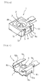
- a chip-type connector 1 is formed as an insert-resin-molded product.
- the connector comprises an outer conductor 2 as a first metallic member, an inner conductor 3 as a second metallic member, and resin 4 which is molded by means of integrating resin with the metallic members.
- the outer conductor 2 and the inner conductor 3 are prepared.
- the former as shown in Fig. 5, is formed by a substantially pipe-shaped cylindrical portion 6 at the center thereof, a flange-like top surface portion 7 formed at one end of the substantially pipe-shaped cylindrical portion 6, metallic parts 8a and 8b which are formed by bending the end portions of the top surface portion 7 in the direction of the substantially pipe-shaped cylindrical portion 6, and legs 9a and 9b connected to the ends of the metallic parts 8a and 8b.
- the metallic parts 8a and 8b have through-holes 10a and 10b disposed at approximately the respective centers thereof.
- the metallic parts 8a and 8b have shapes that substantially resemble the letter "U".
- the through-holes 10a and 10b are made by cutting out two respective portions on the top surface portion 7.
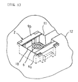
- a resin-molding mold 32 which has a cavity 31 capable of accommodating the outer conductor 2 and the inner conductor 3.
- the cavity 31 is formed into a rectangular parallelepiped, at the center of which a protrusion 34 is disposed so as to be fitted into the inner periphery of the cylindrical portion 6 of the outer conductor 2.
- Inner walls 33 of the cavity 31 are flat, except for the region of the protrusion 34.
- the resin-molding mold 32 shown in Fig. 6 forms a lower mold portion.
- An associated upper mold portion which is not shown in Fig. 6, is equipped with a gate for injecting resin. The upper mold portion lays flat across and encloses the upper opening 35 of the cavity 31.
- the outer conductor 2 and the inner conductor 3 are accommodated in a state in which these components remain insulated from each other.
- Molten resin 4 is injected into the cavity 31 of the resin-molding mold 32 after the upper opening 35 of the cavity 31 is enclosed by the upper mold portion. After the resin 4 injected into the cavity 31 has set, the whole device is taken out from the resin-molding mold 32. A chip-type connector 1 is thereby obtained. More specifically, the device obtained is an insert-resin-molded product integrating the outer conductor 2, the inner conductor 3 and the resin 4 into a unit, as shown in Fig. 4.
- the end portions S1 and S3 and the center portion S2 of the resin side surface, which are connected to the metallic part 8a, are formed flush with the surface of the metallic part 8a of the outer conductor 2.
- the side surface A of the chip-type connector 1 is made flat in conformity with the configuration of the flat inner wall 33 of the cavity 31, which corresponds to the side surface A, as shown in Fig. 6.
- the resin 4 may flow over the surface of the corner portion of the metallic part 8a in a manner similar to that described above. Consequently, resin is deposited on the surface of the metallic part 8a, so that resin burrs 51 (shown in Fig. 4) are generated.
- the present invention has been made with a view toward solving at least the above-noted problems. Accordingly, it is an object of the present invention to provide a method for manufacturing an insert-resin-molded product, in which the generation of resin burrs on the surface of a metallic member, caused by insert-resin-molding, is prevented.
- a method for manufacturing an insert-resin-molded product comprising the steps of: preparing a resin-molding mold having a cavity with an inner wall having a recess therein; preparing a metallic member to be placed in the cavity and to be integrally molded with resin, the metallic member having a metallic part which fits into the recess of the resin-molding mold; placing the metallic member in the cavity of the resin-molding mold and fitting the metallic part of the metallic member into the recess of the resin-molding mold; and, in this state, injecting resin into the cavity of the resin-molding mold to insert-resin-mold integrally with the metallic member.
- the recess of the resin-molding mold is formed in such a manner that the side surface of the recess is substantially perpendicular to the bottom surface of the same. This allows the flow of the molten resin to be substantially perpendicular to the side surface of the metallic member, so that the resin does not flow in the direction of the side surface of the metallic member, thereby, preventing resin burrs from being generated.
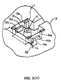
- a chip-type connector 21 formed as an insert-resin-molded product, which comprises an outer conductor 2 as a first metallic member, an inner conductor 3 as a second metallic member and resin 22 molded integrally with the above-identified metallic members.
- the outer conductor 2 and the inner conductor 3, which are metallic members, are prepared.
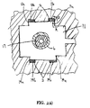
- a resin-molding mold 12 which has a cavity 11 capable of accommodating the conductors 2 and 3 therein, is prepared.
- Through-holes 10a and 10b of the outer conductor 2 are formed to define substantially U-shaped metallic parts 8a and 8b.
- Substantially U-shaped recesses 13 and 14 are disposed on opposing inner walls of the cavity 11. The metallic parts 8a and 8b are respectively fit into the recesses 13 and 14.
- the vertical side surfaces 13a and 14a of the recesses 13 and 14 are formed approximately perpendicularly to bottom surfaces 13b and 14b of the recesses 13 and 14, and more generally, all of the adjoining surfaces which form the recesses 13 and 14 can be disposed perpendicularly to each other.
- a protrusion 17 is disposed at the center of the cavity 11, into which an inner periphery of a substantially pipe-shaped cylindrical portion 6 is fit.
- a resin-molding mold 12 shown in Fig. 2 forms a lower mold portion.
- the outer conductor 2, and the inner conductor 3 are accommodated in the cavity 11 of the resin-molding mold 12 in a state in which they remain insulated from each other.
- a molten resin 22 is injected into the cavity 11 of the resin-molding mold 12 after the top opening 18 of the cavity 11 is enclosed by placing the upper mold portion flat across the top opening 18.
- a chip-type connector 21 shown in Fig. 1 is thereby obtained, which comprises an insert-resin-molded product made by means of integrating the outer conductor 2, the inner conductor 3, and the resin 22 into a unit.
- the surface of the metallic part 8a of the outer conductor 2, and S4, S5 and S6 which are resin surface portions connected to the metallic part 8a, are not flush with each other. Namely, the metallic part 8a fitted into the recess 13 which is disposed in the cavity 11 of the resin-molding mold 12 protrudes out, and steps are formed in such a manner that the resin surface portions S4, S5 and S6 connected to the metallic part 8a are recessed with respect to the metallic part 8a.
- the filling of the cavity 11 with an excessive amount of resin 22 causes the resin 22 to be connected to an end surface 8a1 of the metallic part 8a. Then, resin 22a flush with the end surface 8a1 flows in the direction of the end surface 8a1. That is, the resin 22a flows in the direction of a side surface 13a of the recess 13 of the cavity 11.
- Fig.2(b) shows a sectional view taken along the line A-A of Fig.2(a), with the outer conductor 2 fit into the recesses 13 and 14 of the cavity 11.
- the resin 22a changes its direction of flow in the direction of 90° to the direction of the bottom surface 13b from the direction of the side surface 13a. That is, the resin flows in the direction of the arrow «R», but does not readily flow in the direction of arrow «S».
- the recesses 13 and 14 are arranged respectively on the opposing side surfaces of the cavity as shown in Fig. 2.
- This arrangement pennits formation of steps on the resin surface portions connected to the metallic parts 8a and 8b with respect to the metallic parts 8a and 8b of the outer conductor 2.
- an arrangement of a recess in the bottom surface of the cavity 11 may permit formation of a step (not shown) on the resin surface portion S7 connected to a top surface portion 7 of the outer conductor 2.
- an arrangement of a recess on the top surface portion of the cavity 11 may allow a step (not shown) to be formed on a resin surface portion S8 connected to legs 9a and 9b of the outer conductor 2.
- the thickness of the steps between a surface of the metallic part 8a and the resin surface portions S4 and S6 may be larger than that of the metallic part 8a.
- the thickness of the step between the surface of the metallic part 8a and the resin surface portion S5 may be approximately the same as that of the metallic part 8a. However, this should not be construed restrictively. A thinner step portion than the thickness of the metallic part 8a can be used.
- a recess in an inner wall of a cavity of a resin-molding mold is arranged and the metallic part of a metallic member is fitted into the recess.
- This arrangement allows the route of an injected resin to be turned in the middle of the process (e.g. allows the flow of the resin to be changed in the course of the resin-filling process, such as in the manner shown in Fig.2(b)), so that insert-resin-molding with the metallic member in an integrated manner does not permit the resin to reach the surface of the metallic member. Hence, metallic burrs are not generated.
- metallic burrs are not generated on the surface of the metallic member, since the route of the injected resin turns in a direction substantially at a right angle in the middle of the process for reaching the surface of the metallic part.
Landscapes
- Engineering & Computer Science (AREA)
- Manufacturing & Machinery (AREA)
- Mechanical Engineering (AREA)
- Injection Moulding Of Plastics Or The Like (AREA)
- Moulds For Moulding Plastics Or The Like (AREA)
Applications Claiming Priority (3)
| Application Number | Priority Date | Filing Date | Title |
|---|---|---|---|
| JP25530297 | 1997-09-19 | ||
| JP255302/97 | 1997-09-19 | ||
| JP25530297A JP3269436B2 (ja) | 1997-09-19 | 1997-09-19 | インサート樹脂成形品の製造方法 |
Publications (2)
| Publication Number | Publication Date |
|---|---|
| EP0904920A2 true EP0904920A2 (de) | 1999-03-31 |
| EP0904920A3 EP0904920A3 (de) | 2000-01-19 |
Family
ID=17276896
Family Applications (1)
| Application Number | Title | Priority Date | Filing Date |
|---|---|---|---|
| EP98402306A Withdrawn EP0904920A3 (de) | 1997-09-19 | 1998-09-17 | Verfahren zur Herstellung eines Kunststofformteils mit Einsatz und so hergestelltes Formteil |
Country Status (5)
| Country | Link |
|---|---|
| US (2) | US6212755B1 (de) |
| EP (1) | EP0904920A3 (de) |
| JP (1) | JP3269436B2 (de) |
| KR (1) | KR100289827B1 (de) |
| CN (1) | CN1137020C (de) |
Cited By (2)
| Publication number | Priority date | Publication date | Assignee | Title |
|---|---|---|---|---|
| EP1283536A3 (de) * | 2001-08-10 | 2004-06-16 | Carl Freudenberg KG | Elektrisches Gerät mit einer Wandung aus Kunststoff, umfassend zumindest einen flexiblen Leiter, sowie ein Verfahren zur Herstellung enes solchen elektrischen Gerätes |
| CN112895337A (zh) * | 2021-03-29 | 2021-06-04 | 深圳市创益通技术股份有限公司 | Smp母座自动化生产注塑模具结构 |
Families Citing this family (88)
| Publication number | Priority date | Publication date | Assignee | Title |
|---|---|---|---|---|
| CN1079318C (zh) * | 1999-05-21 | 2002-02-20 | 袁俊 | 斑铜件表面覆层法 |
| JP3730449B2 (ja) * | 1999-08-05 | 2006-01-05 | 矢崎総業株式会社 | レバー嵌合式コネクタおよびコネクタ本体の形成方法 |
| US6869292B2 (en) * | 2001-07-31 | 2005-03-22 | Fci Americas Technology, Inc. | Modular mezzanine connector |
| US6981883B2 (en) * | 2001-11-14 | 2006-01-03 | Fci Americas Technology, Inc. | Impedance control in electrical connectors |
| US6994569B2 (en) | 2001-11-14 | 2006-02-07 | Fci America Technology, Inc. | Electrical connectors having contacts that may be selectively designated as either signal or ground contacts |
| US20050196987A1 (en) * | 2001-11-14 | 2005-09-08 | Shuey Joseph B. | High density, low noise, high speed mezzanine connector |
| EP2451026A3 (de) * | 2001-11-14 | 2013-04-03 | Fci | Gegenseitige Störbeeinflussung für elektrische Anschlüsse |
| US7390200B2 (en) | 2001-11-14 | 2008-06-24 | Fci Americas Technology, Inc. | High speed differential transmission structures without grounds |
| US6652318B1 (en) | 2002-05-24 | 2003-11-25 | Fci Americas Technology, Inc. | Cross-talk canceling technique for high speed electrical connectors |
| US6899548B2 (en) * | 2002-08-30 | 2005-05-31 | Fci Americas Technology, Inc. | Electrical connector having a cored contact assembly |
| US7008250B2 (en) * | 2002-08-30 | 2006-03-07 | Fci Americas Technology, Inc. | Connector receptacle having a short beam and long wipe dual beam contact |
| US7270573B2 (en) * | 2002-08-30 | 2007-09-18 | Fci Americas Technology, Inc. | Electrical connector with load bearing features |
| US20040147169A1 (en) | 2003-01-28 | 2004-07-29 | Allison Jeffrey W. | Power connector with safety feature |
| US7018246B2 (en) * | 2003-03-14 | 2006-03-28 | Fci Americas Technology, Inc. | Maintenance of uniform impedance profiles between adjacent contacts in high speed grid array connectors |
| US7083432B2 (en) * | 2003-08-06 | 2006-08-01 | Fci Americas Technology, Inc. | Retention member for connector system |
| US7524209B2 (en) | 2003-09-26 | 2009-04-28 | Fci Americas Technology, Inc. | Impedance mating interface for electrical connectors |
| US7517250B2 (en) * | 2003-09-26 | 2009-04-14 | Fci Americas Technology, Inc. | Impedance mating interface for electrical connectors |
| CN101882718B (zh) | 2003-12-31 | 2012-11-21 | Fci公司 | 电源触头及包括电源触头的连接器 |
| US7458839B2 (en) * | 2006-02-21 | 2008-12-02 | Fci Americas Technology, Inc. | Electrical connectors having power contacts with alignment and/or restraining features |
| US7242325B2 (en) * | 2004-08-02 | 2007-07-10 | Sony Corporation | Error correction compensating ones or zeros string suppression |
| US7160117B2 (en) * | 2004-08-13 | 2007-01-09 | Fci Americas Technology, Inc. | High speed, high signal integrity electrical connectors |
| CN101076674B (zh) * | 2004-08-24 | 2011-03-23 | 金桂烈 | 夹紧装置及其制造方法 |
| US7214104B2 (en) * | 2004-09-14 | 2007-05-08 | Fci Americas Technology, Inc. | Ball grid array connector |
| US7281950B2 (en) * | 2004-09-29 | 2007-10-16 | Fci Americas Technology, Inc. | High speed connectors that minimize signal skew and crosstalk |
| TWM270536U (en) * | 2004-12-10 | 2005-07-11 | Advanced Connectek Inc | Coaxial connector |
| US7476108B2 (en) * | 2004-12-22 | 2009-01-13 | Fci Americas Technology, Inc. | Electrical power connectors with cooling features |
| US7226296B2 (en) * | 2004-12-23 | 2007-06-05 | Fci Americas Technology, Inc. | Ball grid array contacts with spring action |
| US7384289B2 (en) * | 2005-01-31 | 2008-06-10 | Fci Americas Technology, Inc. | Surface-mount connector |
| US7303427B2 (en) * | 2005-04-05 | 2007-12-04 | Fci Americas Technology, Inc. | Electrical connector with air-circulation features |
| US20060228912A1 (en) * | 2005-04-07 | 2006-10-12 | Fci Americas Technology, Inc. | Orthogonal backplane connector |
| US20060245137A1 (en) * | 2005-04-29 | 2006-11-02 | Fci Americas Technology, Inc. | Backplane connectors |
| US7396259B2 (en) * | 2005-06-29 | 2008-07-08 | Fci Americas Technology, Inc. | Electrical connector housing alignment feature |
| US7819708B2 (en) * | 2005-11-21 | 2010-10-26 | Fci Americas Technology, Inc. | Receptacle contact for improved mating characteristics |
| US7425145B2 (en) * | 2006-05-26 | 2008-09-16 | Fci Americas Technology, Inc. | Connectors and contacts for transmitting electrical power |
| US7726982B2 (en) | 2006-06-15 | 2010-06-01 | Fci Americas Technology, Inc. | Electrical connectors with air-circulation features |
| US7462924B2 (en) * | 2006-06-27 | 2008-12-09 | Fci Americas Technology, Inc. | Electrical connector with elongated ground contacts |
| US8142236B2 (en) * | 2006-08-02 | 2012-03-27 | Tyco Electronics Corporation | Electrical connector having improved density and routing characteristics and related methods |
| US7753742B2 (en) * | 2006-08-02 | 2010-07-13 | Tyco Electronics Corporation | Electrical terminal having improved insertion characteristics and electrical connector for use therewith |
| US7549897B2 (en) * | 2006-08-02 | 2009-06-23 | Tyco Electronics Corporation | Electrical connector having improved terminal configuration |
| US7670196B2 (en) * | 2006-08-02 | 2010-03-02 | Tyco Electronics Corporation | Electrical terminal having tactile feedback tip and electrical connector for use therewith |
| US7591655B2 (en) * | 2006-08-02 | 2009-09-22 | Tyco Electronics Corporation | Electrical connector having improved electrical characteristics |
| US7500871B2 (en) * | 2006-08-21 | 2009-03-10 | Fci Americas Technology, Inc. | Electrical connector system with jogged contact tails |
| US7713088B2 (en) | 2006-10-05 | 2010-05-11 | Fci | Broadside-coupled signal pair configurations for electrical connectors |
| US7708569B2 (en) | 2006-10-30 | 2010-05-04 | Fci Americas Technology, Inc. | Broadside-coupled signal pair configurations for electrical connectors |
| US7497736B2 (en) * | 2006-12-19 | 2009-03-03 | Fci Americas Technology, Inc. | Shieldless, high-speed, low-cross-talk electrical connector |
| US20080203547A1 (en) * | 2007-02-26 | 2008-08-28 | Minich Steven E | Insert molded leadframe assembly |
| US7641500B2 (en) * | 2007-04-04 | 2010-01-05 | Fci Americas Technology, Inc. | Power cable connector system |
| US7905731B2 (en) * | 2007-05-21 | 2011-03-15 | Fci Americas Technology, Inc. | Electrical connector with stress-distribution features |
| US7811100B2 (en) * | 2007-07-13 | 2010-10-12 | Fci Americas Technology, Inc. | Electrical connector system having a continuous ground at the mating interface thereof |
| US7762857B2 (en) | 2007-10-01 | 2010-07-27 | Fci Americas Technology, Inc. | Power connectors with contact-retention features |
| US8764464B2 (en) | 2008-02-29 | 2014-07-01 | Fci Americas Technology Llc | Cross talk reduction for high speed electrical connectors |
| JP4380775B1 (ja) * | 2008-05-29 | 2009-12-09 | トヨタ自動車株式会社 | Frp部材の製造方法及びfrp部材 |
| US8062051B2 (en) | 2008-07-29 | 2011-11-22 | Fci Americas Technology Llc | Electrical communication system having latching and strain relief features |
| US8545240B2 (en) | 2008-11-14 | 2013-10-01 | Molex Incorporated | Connector with terminals forming differential pairs |
| MY155071A (en) | 2008-12-12 | 2015-08-28 | Molex Inc | Resonance modifying connector |
| KR101495201B1 (ko) | 2008-12-19 | 2015-02-24 | 삼성전자주식회사 | 테스트 핸들러용 인서트 모듈 및 이의 제조 방법 |
| USD664096S1 (en) | 2009-01-16 | 2012-07-24 | Fci Americas Technology Llc | Vertical electrical connector |
| USD608293S1 (en) | 2009-01-16 | 2010-01-19 | Fci Americas Technology, Inc. | Vertical electrical connector |
| USD606496S1 (en) | 2009-01-16 | 2009-12-22 | Fci Americas Technology, Inc. | Right-angle electrical connector |
| USD640637S1 (en) | 2009-01-16 | 2011-06-28 | Fci Americas Technology Llc | Vertical electrical connector |
| USD610548S1 (en) | 2009-01-16 | 2010-02-23 | Fci Americas Technology, Inc. | Right-angle electrical connector |
| USD606497S1 (en) | 2009-01-16 | 2009-12-22 | Fci Americas Technology, Inc. | Vertical electrical connector |
| US8323049B2 (en) | 2009-01-30 | 2012-12-04 | Fci Americas Technology Llc | Electrical connector having power contacts |
| USD619099S1 (en) | 2009-01-30 | 2010-07-06 | Fci Americas Technology, Inc. | Electrical connector |
| US9277649B2 (en) | 2009-02-26 | 2016-03-01 | Fci Americas Technology Llc | Cross talk reduction for high-speed electrical connectors |
| US8366485B2 (en) | 2009-03-19 | 2013-02-05 | Fci Americas Technology Llc | Electrical connector having ribbed ground plate |
| USD618180S1 (en) | 2009-04-03 | 2010-06-22 | Fci Americas Technology, Inc. | Asymmetrical electrical connector |
| USD618181S1 (en) | 2009-04-03 | 2010-06-22 | Fci Americas Technology, Inc. | Asymmetrical electrical connector |
| US8608510B2 (en) * | 2009-07-24 | 2013-12-17 | Fci Americas Technology Llc | Dual impedance electrical connector |
| US8267721B2 (en) | 2009-10-28 | 2012-09-18 | Fci Americas Technology Llc | Electrical connector having ground plates and ground coupling bar |
| US8616919B2 (en) | 2009-11-13 | 2013-12-31 | Fci Americas Technology Llc | Attachment system for electrical connector |
| CN102725919B (zh) * | 2009-12-30 | 2015-07-08 | Fci公司 | 具有阻抗调节肋的电连接器 |
| US9136634B2 (en) | 2010-09-03 | 2015-09-15 | Fci Americas Technology Llc | Low-cross-talk electrical connector |
| DE102011006557A1 (de) * | 2011-03-31 | 2012-10-04 | Evonik Oxeno Gmbh | Gemisch von Bersteinsäureestern |
| US20120291599A1 (en) * | 2011-05-19 | 2012-11-22 | Brian James Cutler | Cam Assembly |
| EP2624034A1 (de) | 2012-01-31 | 2013-08-07 | Fci | Abbaubare optische Kupplungsvorrichtung |
| USD718253S1 (en) | 2012-04-13 | 2014-11-25 | Fci Americas Technology Llc | Electrical cable connector |
| USD727852S1 (en) | 2012-04-13 | 2015-04-28 | Fci Americas Technology Llc | Ground shield for a right angle electrical connector |
| US9257778B2 (en) | 2012-04-13 | 2016-02-09 | Fci Americas Technology | High speed electrical connector |
| USD727268S1 (en) | 2012-04-13 | 2015-04-21 | Fci Americas Technology Llc | Vertical electrical connector |
| US8944831B2 (en) | 2012-04-13 | 2015-02-03 | Fci Americas Technology Llc | Electrical connector having ribbed ground plate with engagement members |
| USD751507S1 (en) | 2012-07-11 | 2016-03-15 | Fci Americas Technology Llc | Electrical connector |
| US9543703B2 (en) | 2012-07-11 | 2017-01-10 | Fci Americas Technology Llc | Electrical connector with reduced stack height |
| CN103660130B (zh) * | 2012-09-17 | 2017-05-03 | 技嘉科技股份有限公司 | 异质构件的结合方法及其异质结合构件 |
| USD745852S1 (en) | 2013-01-25 | 2015-12-22 | Fci Americas Technology Llc | Electrical connector |
| USD720698S1 (en) | 2013-03-15 | 2015-01-06 | Fci Americas Technology Llc | Electrical cable connector |
| CN106182581A (zh) * | 2016-07-25 | 2016-12-07 | 胡小庆 | 一种电子芯片的制备方法及电子芯片 |
| JP7842677B2 (ja) * | 2022-11-21 | 2026-04-08 | プライムプラネットエナジー&ソリューションズ株式会社 | 蓄電デバイスの製造方法及び蓄電デバイス |
Family Cites Families (9)
| Publication number | Priority date | Publication date | Assignee | Title |
|---|---|---|---|---|
| US2937409A (en) * | 1954-02-09 | 1960-05-24 | Gen Motors Corp | Method of manufacture |
| AU475619B2 (en) * | 1974-02-23 | 1976-08-26 | Yuko Shendosho Company Limited | pin PLUG |
| US4556190A (en) * | 1983-12-05 | 1985-12-03 | Lyall Electric, Inc. | Mold for grommet mounted connector |
| EP0696089B1 (de) * | 1989-09-25 | 2002-04-10 | Murata Manufacturing Co., Ltd. | Steckverbinder |
| EP0545289B1 (de) * | 1991-11-30 | 1997-03-05 | Murata Manufacturing Co., Ltd. | Koaxialleiter/Mikrostreifenleitungsübergang |
| US5525075A (en) * | 1992-11-30 | 1996-06-11 | Murata Manufacturing Co., Ltd. | Coaxial microstripline transducer |
| JP2827775B2 (ja) * | 1992-12-25 | 1998-11-25 | 豊田合成株式会社 | 樹脂製品の製造方法 |
| JP2927695B2 (ja) * | 1995-02-16 | 1999-07-28 | 矢崎総業株式会社 | フラットケーブルの導通接続部の保護方法及びその保護構造。 |
| US6074217A (en) * | 1995-05-25 | 2000-06-13 | Murata Manufacturing Co., Ltd. | Coaxial connector receptacle |
-
1997
- 1997-09-19 JP JP25530297A patent/JP3269436B2/ja not_active Expired - Lifetime
-
1998
- 1998-09-17 EP EP98402306A patent/EP0904920A3/de not_active Withdrawn
- 1998-09-18 CN CNB98119530XA patent/CN1137020C/zh not_active Expired - Lifetime
- 1998-09-18 KR KR1019980038698A patent/KR100289827B1/ko not_active Expired - Lifetime
- 1998-09-18 US US09/156,629 patent/US6212755B1/en not_active Expired - Lifetime
-
2001
- 2001-03-08 US US09/800,671 patent/US20010008041A1/en not_active Abandoned
Cited By (3)
| Publication number | Priority date | Publication date | Assignee | Title |
|---|---|---|---|---|
| EP1283536A3 (de) * | 2001-08-10 | 2004-06-16 | Carl Freudenberg KG | Elektrisches Gerät mit einer Wandung aus Kunststoff, umfassend zumindest einen flexiblen Leiter, sowie ein Verfahren zur Herstellung enes solchen elektrischen Gerätes |
| CN112895337A (zh) * | 2021-03-29 | 2021-06-04 | 深圳市创益通技术股份有限公司 | Smp母座自动化生产注塑模具结构 |
| CN112895337B (zh) * | 2021-03-29 | 2022-08-12 | 深圳市创益通技术股份有限公司 | Smp母座自动化生产注塑模具结构 |
Also Published As
| Publication number | Publication date |
|---|---|
| US6212755B1 (en) | 2001-04-10 |
| US20010008041A1 (en) | 2001-07-19 |
| CN1137020C (zh) | 2004-02-04 |
| EP0904920A3 (de) | 2000-01-19 |
| KR19990029935A (ko) | 1999-04-26 |
| JPH1190957A (ja) | 1999-04-06 |
| JP3269436B2 (ja) | 2002-03-25 |
| CN1212202A (zh) | 1999-03-31 |
| KR100289827B1 (ko) | 2001-05-15 |
Similar Documents
| Publication | Publication Date | Title |
|---|---|---|
| EP0904920A2 (de) | Verfahren zur Herstellung eines Kunststofformteils mit Einsatz und so hergestelltes Formteil | |
| US6219913B1 (en) | Connector producing method and a connector produced by insert molding | |
| US6174203B1 (en) | Connector with housing insert molded to a magnetic element | |
| US8619436B2 (en) | Electrical component and method for making the same | |
| EP1119887B1 (de) | Zweiteiliger mikroelektronischer stecker und methode | |
| EP0500219A1 (de) | Verfahren zur Herstellung einer Metall-Harz-Einlage; Kontaktierungsleiste und Verfahren zu deren Herstellung | |
| KR20170130282A (ko) | 전기 커넥터 및 그 제조 방법 | |
| CN111630733B (zh) | 电连接器的制造方法以及电连接器 | |
| US5714174A (en) | Apparatus for manufacturing a waterproof connector housing | |
| JPH11502359A (ja) | 電磁リレー | |
| JPH04269478A (ja) | コネクタ及びその製造方法 | |
| WO2020004077A1 (ja) | 遮蔽板を有する電気コネクタ、及び、該電気コネクタのハウジングの製造方法 | |
| US4568795A (en) | Insulation filled carrier of conductive components | |
| JP6897332B2 (ja) | コネクタ | |
| CN117241470A (zh) | 电子部件 | |
| JP2759637B2 (ja) | Icソケット | |
| JP2786667B2 (ja) | 電気部品列の製造型 | |
| EP0446489B1 (de) | Elektronisches Gerät und Klemme dafür | |
| JP3184238B2 (ja) | 梯子型電気濾波器の封止方法 | |
| JP3315939B2 (ja) | モータ | |
| JP2599315B2 (ja) | パルストランスの製造方法 | |
| JPH02273486A (ja) | 電気部品列の製造型 | |
| JP2586204B2 (ja) | カプラー付きケース用端子組立方法 | |
| JP2705099B2 (ja) | 電気回路部品 | |
| JPH10200361A (ja) | 圧電部品及びその製造方法 |
Legal Events
| Date | Code | Title | Description |
|---|---|---|---|
| PUAI | Public reference made under article 153(3) epc to a published international application that has entered the european phase |
Free format text: ORIGINAL CODE: 0009012 |
|
| AK | Designated contracting states |
Kind code of ref document: A2 Designated state(s): DE FR GB |
|
| AX | Request for extension of the european patent |
Free format text: AL;LT;LV;MK;RO;SI |
|
| PUAL | Search report despatched |
Free format text: ORIGINAL CODE: 0009013 |
|
| AK | Designated contracting states |
Kind code of ref document: A3 Designated state(s): AT BE CH CY DE DK ES FI FR GB GR IE IT LI LU MC NL PT SE |
|
| AX | Request for extension of the european patent |
Free format text: AL;LT;LV;MK;RO;SI |
|
| RIC1 | Information provided on ipc code assigned before grant |
Free format text: 7B 29C 45/14 A, 7H 01R 43/24 B |
|
| 17P | Request for examination filed |
Effective date: 20000718 |
|
| AKX | Designation fees paid |
Free format text: DE FR GB |
|
| 17Q | First examination report despatched |
Effective date: 20010807 |
|
| STAA | Information on the status of an ep patent application or granted ep patent |
Free format text: STATUS: THE APPLICATION IS DEEMED TO BE WITHDRAWN |
|
| 18D | Application deemed to be withdrawn |
Effective date: 20030226 |