EP0900905B1 - Apparatus for controlling power windows - Google Patents
Apparatus for controlling power windows Download PDFInfo
- Publication number
- EP0900905B1 EP0900905B1 EP98307036A EP98307036A EP0900905B1 EP 0900905 B1 EP0900905 B1 EP 0900905B1 EP 98307036 A EP98307036 A EP 98307036A EP 98307036 A EP98307036 A EP 98307036A EP 0900905 B1 EP0900905 B1 EP 0900905B1
- Authority
- EP
- European Patent Office
- Prior art keywords
- switch
- auto
- manual
- main body
- motor
- Prior art date
- Legal status (The legal status is an assumption and is not a legal conclusion. Google has not performed a legal analysis and makes no representation as to the accuracy of the status listed.)
- Expired - Lifetime
Links
- 230000007935 neutral effect Effects 0.000 description 5
- 238000010276 construction Methods 0.000 description 3
- 238000005192 partition Methods 0.000 description 3
Images


Classifications
-
- H—ELECTRICITY
- H01—ELECTRIC ELEMENTS
- H01H—ELECTRIC SWITCHES; RELAYS; SELECTORS; EMERGENCY PROTECTIVE DEVICES
- H01H23/00—Tumbler or rocker switches, i.e. switches characterised by being operated by rocking an operating member in the form of a rocker button
- H01H23/003—Tumbler or rocker switches, i.e. switches characterised by being operated by rocking an operating member in the form of a rocker button with more than one electrically distinguishable condition in one or both positions
-
- E—FIXED CONSTRUCTIONS
- E05—LOCKS; KEYS; WINDOW OR DOOR FITTINGS; SAFES
- E05F—DEVICES FOR MOVING WINGS INTO OPEN OR CLOSED POSITION; CHECKS FOR WINGS; WING FITTINGS NOT OTHERWISE PROVIDED FOR, CONCERNED WITH THE FUNCTIONING OF THE WING
- E05F15/00—Power-operated mechanisms for wings
- E05F15/60—Power-operated mechanisms for wings using electrical actuators
- E05F15/603—Power-operated mechanisms for wings using electrical actuators using rotary electromotors
- E05F15/665—Power-operated mechanisms for wings using electrical actuators using rotary electromotors for vertically-sliding wings
- E05F15/689—Power-operated mechanisms for wings using electrical actuators using rotary electromotors for vertically-sliding wings specially adapted for vehicle windows
- E05F15/695—Control circuits therefor
-
- E—FIXED CONSTRUCTIONS
- E05—LOCKS; KEYS; WINDOW OR DOOR FITTINGS; SAFES
- E05F—DEVICES FOR MOVING WINGS INTO OPEN OR CLOSED POSITION; CHECKS FOR WINGS; WING FITTINGS NOT OTHERWISE PROVIDED FOR, CONCERNED WITH THE FUNCTIONING OF THE WING
- E05F15/00—Power-operated mechanisms for wings
-
- E—FIXED CONSTRUCTIONS
- E05—LOCKS; KEYS; WINDOW OR DOOR FITTINGS; SAFES
- E05Y—INDEXING SCHEME ASSOCIATED WITH SUBCLASSES E05D AND E05F, RELATING TO CONSTRUCTION ELEMENTS, ELECTRIC CONTROL, POWER SUPPLY, POWER SIGNAL OR TRANSMISSION, USER INTERFACES, MOUNTING OR COUPLING, DETAILS, ACCESSORIES, AUXILIARY OPERATIONS NOT OTHERWISE PROVIDED FOR, APPLICATION THEREOF
- E05Y2400/00—Electronic control; Electrical power; Power supply; Power or signal transmission; User interfaces
- E05Y2400/10—Electronic control
- E05Y2400/32—Position control, detection or monitoring
- E05Y2400/35—Position control, detection or monitoring related to specific positions
-
- E—FIXED CONSTRUCTIONS
- E05—LOCKS; KEYS; WINDOW OR DOOR FITTINGS; SAFES
- E05Y—INDEXING SCHEME ASSOCIATED WITH SUBCLASSES E05D AND E05F, RELATING TO CONSTRUCTION ELEMENTS, ELECTRIC CONTROL, POWER SUPPLY, POWER SIGNAL OR TRANSMISSION, USER INTERFACES, MOUNTING OR COUPLING, DETAILS, ACCESSORIES, AUXILIARY OPERATIONS NOT OTHERWISE PROVIDED FOR, APPLICATION THEREOF
- E05Y2400/00—Electronic control; Electrical power; Power supply; Power or signal transmission; User interfaces
- E05Y2400/80—User interfaces
- E05Y2400/85—User input means
- E05Y2400/852—Sensors
- E05Y2400/854—Switches
-
- E—FIXED CONSTRUCTIONS
- E05—LOCKS; KEYS; WINDOW OR DOOR FITTINGS; SAFES
- E05Y—INDEXING SCHEME ASSOCIATED WITH SUBCLASSES E05D AND E05F, RELATING TO CONSTRUCTION ELEMENTS, ELECTRIC CONTROL, POWER SUPPLY, POWER SIGNAL OR TRANSMISSION, USER INTERFACES, MOUNTING OR COUPLING, DETAILS, ACCESSORIES, AUXILIARY OPERATIONS NOT OTHERWISE PROVIDED FOR, APPLICATION THEREOF
- E05Y2400/00—Electronic control; Electrical power; Power supply; Power or signal transmission; User interfaces
- E05Y2400/80—User interfaces
- E05Y2400/85—User input means
- E05Y2400/856—Actuation thereof
- E05Y2400/858—Actuation thereof by body parts, e.g. by feet
- E05Y2400/86—Actuation thereof by body parts, e.g. by feet by hand
-
- E—FIXED CONSTRUCTIONS
- E05—LOCKS; KEYS; WINDOW OR DOOR FITTINGS; SAFES
- E05Y—INDEXING SCHEME ASSOCIATED WITH SUBCLASSES E05D AND E05F, RELATING TO CONSTRUCTION ELEMENTS, ELECTRIC CONTROL, POWER SUPPLY, POWER SIGNAL OR TRANSMISSION, USER INTERFACES, MOUNTING OR COUPLING, DETAILS, ACCESSORIES, AUXILIARY OPERATIONS NOT OTHERWISE PROVIDED FOR, APPLICATION THEREOF
- E05Y2900/00—Application of doors, windows, wings or fittings thereof
- E05Y2900/50—Application of doors, windows, wings or fittings thereof for vehicles
- E05Y2900/53—Type of wing
- E05Y2900/55—Windows
-
- H—ELECTRICITY
- H01—ELECTRIC ELEMENTS
- H01H—ELECTRIC SWITCHES; RELAYS; SELECTORS; EMERGENCY PROTECTIVE DEVICES
- H01H21/00—Switches operated by an operating part in the form of a pivotable member acted upon directly by a solid body, e.g. by a hand
- H01H21/02—Details
- H01H21/18—Movable parts; Contacts mounted thereon
- H01H21/22—Operating parts, e.g. handle
- H01H2021/225—Operating parts, e.g. handle with push-pull operation, e.g. which can be pivoted in both directions by pushing or pulling on the same extremity of the operating member
-
- H—ELECTRICITY
- H01—ELECTRIC ELEMENTS
- H01H—ELECTRIC SWITCHES; RELAYS; SELECTORS; EMERGENCY PROTECTIVE DEVICES
- H01H2300/00—Orthogonal indexing scheme relating to electric switches, relays, selectors or emergency protective devices covered by H01H
- H01H2300/01—Application power window
Definitions
- This invention relates to apparatus for controlling the motors of power windows (see JP-A-08022744).
- motor controlling apparatus for a power window comprises a plurality of control knobs for switching on and off a motor for each window in manual fashion, a switch board provided with a plurality of inner switches corresponding to the said control knobs, and a relay. board having relays driven by an output of the switch board, the switch board and the relay board being superposed in the vertical direction.
- a master switch comprising a manual switch and an auto switch
- the manual switch is arranged to operate a window by making a motor rotate in forward and reverse directions by moving a V-shaped pivoting contact in an operational direction of a control knob
- the auto switch is provided with a mechanical type contact holding means using a solenoid.
- an object of the present invention is to simplify the whole construction by employing an auto switch using a relay, and to make the whole apparatus compact by making a manual circuit as small as possible.
- apparatus for controlling the motors of power windows comprising:
- the auto switch can be simply constructed and the manual circuit in the auto switch can be integrated with the auto circuit board.
- the apparatus becomes more compact.
- the whole apparatus can be made more compact.
- the said auto switch is arranged to be controlled by a knob on the opposite side of the said auto circuit board across the said main body, by way of a through hole formed in the said main body.
- the auto switch is adapted to be operated through a through hole in the main body, the auto circuit board can be arranged to overlap with the manual circuit formed on the main body, and the whole apparatus can be made more compact.
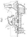
- this master switch comprises a driver's window switch 1 constructed as an auto switch, a passenger's window switch 2 constructed as a manual switch, and a main switch 3 for switching on or off the operation of the switches 1 and 2.
- the driver's switch 1 comprises a knob 7 mounted to pivot freely up and down on a shaft 6 mounted on a switch base 5 which projects upward from a resin-formed main body 4 of the window control equipment.
- An arm 8 is arranged to pivot together with the knob 7 and is engaged with a slider 9 whose movement thus follows the pivoting of the arm 8.
- An auto circuit board 11 includes a stationary contact (described later) for engaging a movable contact 10 of the slider 9.
- the knob 7 is pivotable two steps around the shaft 6, respectively clockwise and counterclockwise from a neutral position N. In the clockwise direction it is pivotable to a manual down position MD and an auto down position AD, while in the counterclockwise direction it is pivotable to a manual up position MU and an auto up position AU.
- the switch base 5 is in the form of a substantially square hollow pillar, with a partition wall 5a formed in the middle portion thereof.
- the tip of the arm 8 extends into a recess 12 formed in the main body 4 at a lower level than the partition wall 5a, the arm 8 passing through an elongate slot 5b in the partition wall 5a and engaging with the slider 9 which is arranged to move freely in the recess 12.
- the recess 12 is of dimensions to accommodate the movement of the slider 9.
- a conventional click ditch 5c is formed parallel to the slot to permit pivoting of the knob 7 between the neutral position and the manual and auto positions.
- stationary contacts of the driver's switch 1 are provided on the surface of the auto circuit board 11 facing the recess 12. As shown in Fig. 4, these comprise a ground terminal 13, an auto down terminal 14, a manual down terminal 15, an auto up terminal 16 and a manual up terminal 17, respectively arranged to be a part of a circuit formed on the auto circuit board 11. This circuit is connected to a relay 18 and the output thereof is sent from the auto circuit board 11 to the main body 4 through a connecting portion 19.
- the movable contact 10 is aligned with both the ground terminal 13 and the manual down terminal 15, and the relay 18 is then activated when the knob is pushed down, so as to operate the motor to lower the window.
- the circuit is placed in auto condition in that the movable contact 10 at once contacts the ground terminal 13, the manual down terminal 15, and the auto down terminal 14, without the knob being pushed down, thus causing the motor to operate until the window is fully open.
- the movable contact 10 becomes aligned with both the ground terminal 13 and the manual up terminal 17 to cause the motor to operate in the window closing direction only when the knob is pushed down.
- the ground terminal 13 is at once connected with the auto up terminal 16 so that the motor is caused to operate until the window is fully closed.
- a coupler 20 is formed integrally on the main body 4, into which a plurality of coupler terminals 21 project.
- the coupler terminals 21 comprise end portions of terminal plates 22 insert molded into the main body.
- One of the terminal plates 22 is arranged to transmit the output from the relay 18 to the motor of the driver's window, and another such terminal plate is arranged to transmit the output from the main switch 3 to the motor of the passenger's window and to be the power supply circuit.
- the passenger's window switch 2 is arranged to control the motor for the passenger's window by directly operating a control switch for the motor by way of knob 23 (Fig. 2), in a conventional manner.
- Reference 25 in Fig. 1 indicates a cover for the main body 4 which exposes the knob 7, the knob 23 and a knob 24 of the switch 3.
- Reference 26 indicates a bottom cover which encloses the auto circuit board 11 and the relay 18.
- the auto switch circuit can be integrated with the manual switch circuit, which simplifies the construction.
- the passenger's switch 2 since the passenger's switch 2 has only to operate a manual circuit, it can be made compact.
- the slider 9 is arranged to make a connection with a stationary contact on the auto circuit board 11, by moving the slider by way of the knob 7 through the recess 12 which is a through hole formed in the main body 4, a manual circuit forming portion 27 of the control main body 4 can be made nearly the same size as the auto circuit board 11 and such parts can be superposed one on the other in the vertical direction, whereby the whole apparatus can be made compact.
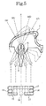
- Fig. 6 is a view showing a contact portion of the driver's switch 1 of a second embodiment.
- the switch 1 includes legs 30 and 31 located symmetrically about the shaft 6 to push down plungers 32 and 33 which are freely movable in the up and down directions on the main body 4.
- the lower ends of the plungers push down conductive rubber contacts 34 and 35 to make contact with a down contact 36 or an up contact 37 of the manual circuit formed on the auto circuit board 11.
- a pair of conductive rubber contacts 38 and 39 also activated by the lower ends of the plungers 32,33 are arranged to contact respectively with a down contact 40 and an up contact 41 of the auto circuit.
- the knob 7 since it is required that the knob 7 is pivotable so that the conductive rubber contacts 38 and 39 on the auto side are not made to contact the down and up contacts 40 and 41 when the knob 7 is on the manual side, the plungers 32,33 on the manual side are provided with coil springs 32a and 33a and the amount of projection of the tip of each plunger 32,33 in the neutral condition is made larger than that on the auto side.
Landscapes
- Power-Operated Mechanisms For Wings (AREA)
- Tumbler Switches (AREA)
- Window Of Vehicle (AREA)
- Keying Circuit Devices (AREA)
Applications Claiming Priority (3)
| Application Number | Priority Date | Filing Date | Title |
|---|---|---|---|
| JP23716697 | 1997-09-02 | ||
| JP237166/97 | 1997-09-02 | ||
| JP23716697A JP3967430B2 (ja) | 1997-09-02 | 1997-09-02 | パワーウインド用モータ制御装置 |
Publications (3)
| Publication Number | Publication Date |
|---|---|
| EP0900905A2 EP0900905A2 (en) | 1999-03-10 |
| EP0900905A3 EP0900905A3 (en) | 1999-09-29 |
| EP0900905B1 true EP0900905B1 (en) | 2002-07-10 |
Family
ID=17011366
Family Applications (1)
| Application Number | Title | Priority Date | Filing Date |
|---|---|---|---|
| EP98307036A Expired - Lifetime EP0900905B1 (en) | 1997-09-02 | 1998-09-02 | Apparatus for controlling power windows |
Country Status (6)
| Country | Link |
|---|---|
| US (1) | US6097105A (ja) |
| EP (1) | EP0900905B1 (ja) |
| JP (1) | JP3967430B2 (ja) |
| KR (1) | KR100555091B1 (ja) |
| CN (1) | CN1116492C (ja) |
| DE (1) | DE69806452T2 (ja) |
Families Citing this family (18)
| Publication number | Priority date | Publication date | Assignee | Title |
|---|---|---|---|---|
| DE19912086A1 (de) * | 1999-03-18 | 2000-09-21 | Eaton Corp | Hub-Schiebe-Schalter |
| JP3798182B2 (ja) * | 1999-06-03 | 2006-07-19 | アルプス電気株式会社 | スイッチ装置 |
| JP2001243850A (ja) * | 1999-12-21 | 2001-09-07 | Niles Parts Co Ltd | 複合スイッチ装置 |
| GB2360632B (en) * | 2000-03-20 | 2004-02-11 | Ford Global Tech Inc | Power window switch |
| US6249732B1 (en) * | 2000-06-16 | 2001-06-19 | Meritor Light Vehicle Technology, Llc | Window characteristic mapping for object detection |
| US6541929B2 (en) * | 2001-02-05 | 2003-04-01 | Trw Inc. | Apparatus and method for controlling vehicle power windows |
| KR20030006471A (ko) * | 2001-07-13 | 2003-01-23 | 엘지이노텍 주식회사 | 모터 제어 시스템 |
| JP2004096918A (ja) * | 2002-09-02 | 2004-03-25 | Omron Corp | スイッチ装置 |
| JP4056961B2 (ja) * | 2003-10-16 | 2008-03-05 | 矢崎総業株式会社 | パワーウインドの駆動装置 |
| JP2008004322A (ja) | 2006-06-21 | 2008-01-10 | Omron Corp | スイッチ |
| KR100872650B1 (ko) | 2006-12-11 | 2008-12-09 | 현대자동차주식회사 | 통합형 파워윈도우 스위치 |
| KR100828852B1 (ko) * | 2006-12-13 | 2008-05-09 | 현대자동차주식회사 | 파워 윈도우 스위치 |
| KR100812475B1 (ko) | 2007-03-09 | 2008-03-10 | 주식회사 신창전기 | 차량용 저부하 스위치 |
| KR200471127Y1 (ko) * | 2009-03-27 | 2014-02-05 | 대성전기공업 주식회사 | 차량용 조수석 도어락 스위치 장치 |
| KR101459920B1 (ko) * | 2013-06-20 | 2014-11-07 | 대성전기공업 주식회사 | 파워 윈도우 스위치 |
| JP6113031B2 (ja) * | 2013-09-06 | 2017-04-12 | オムロンオートモーティブエレクトロニクス株式会社 | パワーウインドウスイッチ、オート開閉機能付きスイッチモジュール |
| KR101599609B1 (ko) * | 2014-05-15 | 2016-03-15 | 대성전기공업 주식회사 | 파워 윈도우 스위치 모듈 |
| JP6304770B2 (ja) * | 2015-05-25 | 2018-04-04 | オムロンオートモーティブエレクトロニクス株式会社 | スイッチ装置 |
Family Cites Families (14)
| Publication number | Priority date | Publication date | Assignee | Title |
|---|---|---|---|---|
| JPS641722Y2 (ja) * | 1979-07-30 | 1989-01-17 | ||
| KR920002963B1 (ko) * | 1988-05-13 | 1992-04-11 | 석윤기 | 자동차용 파워 윈도우 스위치 |
| JPS60178938U (ja) * | 1984-05-08 | 1985-11-28 | 株式会社東海理化電機製作所 | スイツチ |
| FR2604849B1 (fr) * | 1986-10-02 | 1989-01-06 | Dav | Commutateur electrique, notamment pour la commande d'equipements et accessoires automobiles |
| JPH021819A (ja) | 1988-06-13 | 1990-01-08 | Alps Electric Co Ltd | ドツトマトリクス型液晶表示素子の製造方法 |
| JPH0298418A (ja) | 1988-10-04 | 1990-04-10 | Japan Steel Works Ltd:The | 射出計量ストローク自動設定方法およびその装置 |
| US5258593A (en) * | 1991-04-17 | 1993-11-02 | Alps Electric Co., Ltd. | Illuminated see-saw switch device |
| JP2897592B2 (ja) | 1992-05-28 | 1999-05-31 | 住友化学工業株式会社 | 低重合度パラアラミドドープ、それから製造されるパラアラミド繊維およびパラアラミドパルプならびにそれらの製造方法 |
| JP2604614Y2 (ja) * | 1993-03-15 | 2000-05-22 | 東洋電装株式会社 | スイッチ装置 |
| JP2827906B2 (ja) * | 1994-07-07 | 1998-11-25 | 住友電装株式会社 | 車載用パワーウィンドスイッチ |
| US5821483A (en) * | 1995-01-11 | 1998-10-13 | Omron Corporation | Modular array of switches, switch actuators, printed circuit boards, housing and electrical connector |
| JPH08249980A (ja) * | 1995-01-11 | 1996-09-27 | Omron Corp | スイッチ装置 |
| US5598918A (en) * | 1995-05-18 | 1997-02-04 | Trw Inc. | Switch for vehicle power window |
| JPH09102244A (ja) * | 1995-10-03 | 1997-04-15 | Sumitomo Wiring Syst Ltd | パワーウィンドウスイッチ構造 |
-
1997
- 1997-09-02 JP JP23716697A patent/JP3967430B2/ja not_active Expired - Fee Related
-
1998
- 1998-09-01 US US09/144,976 patent/US6097105A/en not_active Expired - Fee Related
- 1998-09-02 DE DE69806452T patent/DE69806452T2/de not_active Expired - Lifetime
- 1998-09-02 CN CN98118825.7A patent/CN1116492C/zh not_active Expired - Fee Related
- 1998-09-02 EP EP98307036A patent/EP0900905B1/en not_active Expired - Lifetime
- 1998-09-02 KR KR1019980036066A patent/KR100555091B1/ko not_active IP Right Cessation
Also Published As
| Publication number | Publication date |
|---|---|
| EP0900905A2 (en) | 1999-03-10 |
| CN1116492C (zh) | 2003-07-30 |
| DE69806452D1 (de) | 2002-08-14 |
| EP0900905A3 (en) | 1999-09-29 |
| KR19990029454A (ko) | 1999-04-26 |
| US6097105A (en) | 2000-08-01 |
| JP3967430B2 (ja) | 2007-08-29 |
| KR100555091B1 (ko) | 2006-04-21 |
| DE69806452T2 (de) | 2003-02-13 |
| JPH1186666A (ja) | 1999-03-30 |
| CN1222633A (zh) | 1999-07-14 |
Similar Documents
| Publication | Publication Date | Title |
|---|---|---|
| EP0900905B1 (en) | Apparatus for controlling power windows | |
| US20050109591A1 (en) | Multiple detent switch | |
| US5720379A (en) | Push-push switch with lock | |
| US5412164A (en) | Dual action switch assembly with sequentially actuated membrane switches including a reciprocating circuit board | |
| US5510583A (en) | Assembly for sequential switching | |
| US5783785A (en) | Switch including two step sequential operation | |
| US6273593B1 (en) | Door and manually actuated vehicle interior lighting system | |
| KR101335002B1 (ko) | 점화 시동 스위칭 장치 | |
| JP2001159270A (ja) | パワーウインド装置 | |
| EP0278536B1 (en) | Control device for a movable part, designed for opening and closing an opening, especially a sliding/tilting roof for a vehicle | |
| US5045654A (en) | Switch assembly | |
| JP4185576B2 (ja) | スイッチ装置 | |
| KR100500086B1 (ko) | 스위치장치 | |
| US5939683A (en) | High/low beam headlamps and fog lamps switch assembly | |
| JPH05314864A (ja) | スイッチ装置 | |
| KR100521984B1 (ko) | 자동차의 미러 조정 스위치 | |
| JP2519813Y2 (ja) | パワーウィンド用スイッチ | |
| US5817995A (en) | Wipe/wash switch | |
| KR100583877B1 (ko) | 미러 스위치 장치 | |
| JPH04253121A (ja) | スイッチ装置 | |
| CA1163697A (en) | Diesel engine shutoff actuator | |
| KR830001427Y1 (ko) | 레바 스위치 장치 | |
| KR100490344B1 (ko) | 자동차의 방향 지시등 스위치 | |
| JPH08212876A (ja) | スイッチ装置 | |
| JP2004146069A (ja) | 2段動作シーソースイッチ装置 |
Legal Events
| Date | Code | Title | Description |
|---|---|---|---|
| PUAI | Public reference made under article 153(3) epc to a published international application that has entered the european phase |
Free format text: ORIGINAL CODE: 0009012 |
|
| AK | Designated contracting states |
Kind code of ref document: A2 Designated state(s): DE FR GB IT |
|
| AX | Request for extension of the european patent |
Free format text: AL;LT;LV;MK;RO;SI |
|
| PUAL | Search report despatched |
Free format text: ORIGINAL CODE: 0009013 |
|
| AK | Designated contracting states |
Kind code of ref document: A3 Designated state(s): AT BE CH CY DE DK ES FI FR GB GR IE IT LI LU MC NL PT SE |
|
| AX | Request for extension of the european patent |
Free format text: AL;LT;LV;MK;RO;SI |
|
| RIC1 | Information provided on ipc code assigned before grant |
Free format text: 6E 05F 15/16 A, 6B 60J 1/17 B, 6H 02P 7/00 B, 6H 01H 21/02 B, 6H 01H 23/02 B, 6H 01H 23/00 B |
|
| 17P | Request for examination filed |
Effective date: 19991227 |
|
| AKX | Designation fees paid |
Free format text: DE FR GB IT |
|
| GRAG | Despatch of communication of intention to grant |
Free format text: ORIGINAL CODE: EPIDOS AGRA |
|
| 17Q | First examination report despatched |
Effective date: 20010920 |
|
| GRAG | Despatch of communication of intention to grant |
Free format text: ORIGINAL CODE: EPIDOS AGRA |
|
| GRAH | Despatch of communication of intention to grant a patent |
Free format text: ORIGINAL CODE: EPIDOS IGRA |
|
| GRAH | Despatch of communication of intention to grant a patent |
Free format text: ORIGINAL CODE: EPIDOS IGRA |
|
| GRAA | (expected) grant |
Free format text: ORIGINAL CODE: 0009210 |
|
| AK | Designated contracting states |
Kind code of ref document: B1 Designated state(s): DE FR GB IT |
|
| REG | Reference to a national code |
Ref country code: GB Ref legal event code: FG4D |
|
| REF | Corresponds to: |
Ref document number: 69806452 Country of ref document: DE Date of ref document: 20020814 |
|
| ET | Fr: translation filed | ||
| PLBE | No opposition filed within time limit |
Free format text: ORIGINAL CODE: 0009261 |
|
| STAA | Information on the status of an ep patent application or granted ep patent |
Free format text: STATUS: NO OPPOSITION FILED WITHIN TIME LIMIT |
|
| 26N | No opposition filed |
Effective date: 20030411 |
|
| PGFP | Annual fee paid to national office [announced via postgrant information from national office to epo] |
Ref country code: GB Payment date: 20090824 Year of fee payment: 12 |
|
| PGFP | Annual fee paid to national office [announced via postgrant information from national office to epo] |
Ref country code: DE Payment date: 20090930 Year of fee payment: 12 |
|
| PGFP | Annual fee paid to national office [announced via postgrant information from national office to epo] |
Ref country code: IT Payment date: 20090915 Year of fee payment: 12 |
|
| GBPC | Gb: european patent ceased through non-payment of renewal fee |
Effective date: 20100902 |
|
| PG25 | Lapsed in a contracting state [announced via postgrant information from national office to epo] |
Ref country code: IT Free format text: LAPSE BECAUSE OF NON-PAYMENT OF DUE FEES Effective date: 20100902 |
|
| REG | Reference to a national code |
Ref country code: FR Ref legal event code: ST Effective date: 20110531 |
|
| REG | Reference to a national code |
Ref country code: DE Ref legal event code: R119 Ref document number: 69806452 Country of ref document: DE Effective date: 20110401 |
|
| PG25 | Lapsed in a contracting state [announced via postgrant information from national office to epo] |
Ref country code: DE Free format text: LAPSE BECAUSE OF NON-PAYMENT OF DUE FEES Effective date: 20110401 Ref country code: FR Free format text: LAPSE BECAUSE OF NON-PAYMENT OF DUE FEES Effective date: 20100930 |
|
| PG25 | Lapsed in a contracting state [announced via postgrant information from national office to epo] |
Ref country code: GB Free format text: LAPSE BECAUSE OF NON-PAYMENT OF DUE FEES Effective date: 20100902 |
|
| PGFP | Annual fee paid to national office [announced via postgrant information from national office to epo] |
Ref country code: FR Payment date: 20090925 Year of fee payment: 12 |