EP0899562B1 - Sauerstoffsensor - Google Patents
Sauerstoffsensor Download PDFInfo
- Publication number
- EP0899562B1 EP0899562B1 EP98306913A EP98306913A EP0899562B1 EP 0899562 B1 EP0899562 B1 EP 0899562B1 EP 98306913 A EP98306913 A EP 98306913A EP 98306913 A EP98306913 A EP 98306913A EP 0899562 B1 EP0899562 B1 EP 0899562B1
- Authority
- EP
- European Patent Office
- Prior art keywords
- filter
- holding part
- filter holding
- casing
- heating element
- Prior art date
- Legal status (The legal status is an assumption and is not a legal conclusion. Google has not performed a legal analysis and makes no representation as to the accuracy of the status listed.)
- Expired - Lifetime
Links
Images


Classifications
-
- G—PHYSICS
- G01—MEASURING; TESTING
- G01N—INVESTIGATING OR ANALYSING MATERIALS BY DETERMINING THEIR CHEMICAL OR PHYSICAL PROPERTIES
- G01N27/00—Investigating or analysing materials by the use of electric, electrochemical, or magnetic means
- G01N27/26—Investigating or analysing materials by the use of electric, electrochemical, or magnetic means by investigating electrochemical variables; by using electrolysis or electrophoresis
- G01N27/403—Cells and electrode assemblies
- G01N27/406—Cells and probes with solid electrolytes
- G01N27/407—Cells and probes with solid electrolytes for investigating or analysing gases
Definitions
- the present invention relates to an oxygen sensor for detecting the oxygen concentration in exhaust gas in an internal combustion engine, for example, or an oxygen sensor for detecting oxygen in a predetermined gas.
- representative one of such oxygen sensors widely used has a structure wherein an oxygen sensing element formed like a hollow shaft closed at the tip made of an oxygen ion conductive solid electrolyte of ZrO 2 , etc., is housed in a cylindrical casing, the outer face of the tip of the oxygen sensing element is brought into contact with a detected atmosphere, and air as a reference gas is introduced into the space inside the oxygen sensing element for measuring the oxygen concentration in the detected atmosphere based on an oxygen concentration cell electromotive force occurring in the sensing element.
- the oxygen sensor By the way, to install an oxygen sensor as described above in an automobile, the oxygen sensor often is attached to an exhaust pipe, etc., near a tire of the vehicle, for example, in addition to an engine room. In such a situation, the oxygen sensor is exposed to a considerable hostile environment in which it receives a jet of water drops at the rainy driving time, at the washing time, etc., dirt of oil, etc., is deposited on the oxygen sensor, or the oxygen sensor receives shock of jumped-up pebbles, etc. In this case, to protect the oxygen sensing element from water drop and dirt deposition, a highly strong and highly sealed structure as much as possible must be adopted as the structure of the casing housing the oxygen sensing element.
- Japanese Patent Laid-Open No. Hei 8-201338 discloses an oxygen sensor of a structure wherein an air hole is made in a casing and is covered with a water repellent filter, whereby ventilation is allowed while the entry of water drops, etc., is blocked.
- a ceramic separator is placed in the casing and leads from the oxygen sensing element or a heating element for heating the oxygen sensing element are passed through lead insertion holes as a structure for drawing out the leads from the casing.
- a ceramic separator prevents or suppresses a short circuit between the leads or terminals following the leads, for example.
- Each lead extends from a rear opening of the casing to the outside and the space between the lead and the opening is sealed by an elastic seal member of a rubber tap, etc., fitted into the opening.
- lead insertion holes made in the ceramic separator and the elastic seal member are formed so that their centers are arranged on a phantom circumferential path (pitch circle).
- the leads are inserted into the elastic seal member and the ceramic separator at different pitch circle diameters and to absorb the pitch circle diameter differences, a comparatively large gap is formed between the elastic seal member and the ceramic separator.
- a ventilation structure consisting of an air hole and a water repellent filter for covering the air hole is provided corresponding to the gap position.
- the ventilation structure containing the water repellent filter is formed corresponding to the gap between the elastic seal member and the ceramic separator, thus if a strong impulse force acts on the part, there is a possibility that the casing will be largely deformed at the position corresponding to the gap. In this case, it is feared that a cylindrical member fixing and sealing the filter from the outside, for example, by crimping may loosen because of the deformation of the casing, that the filter seal may be broken, and that water drops, etc., may bypass the filter and enter the casing through the air hole. Since nothing blocks the way of leaked water drops in the proximity of the air hole, the probability is also high that water drops will leak into the oxygen sensing element through a through hole, etc., made in the axial direction of the ceramic separator, for example.
- the present invention provides an oxygen sensor comprising:
- An oxygen sensor 1 shown in FIG. 1 is formed of an oxygen sensing element 2 of a solid electrolyte member formed like a hollow shaft closed at the tip and a heating element 3 of a ceramic heater like a shaft; it is formed as an assembly of various members making up a crust of the oxygen sensing element 2 and the heating element 3.
- the oxygen sensing element 2 is made of a solid electrolyte having oxygen ion conductivity.
- ZrO 2 provided by solidly solving CaO or Y 2 O 3 is representative as such a solid electrolyte.
- a solid solution of ZrO 2 and an oxide of any other alkali earth metal or rare earth metal may be used.
- ZrO 2 used as a base may contain HfO 2 .
- the oxygen sensing element 2 is formed on the intermediate part outside with insulators 6 and 7 formed of insulating ceramics and a metal casing 10 via ceramic powder 8 formed of talc and pierces in a state in which it is electrically insulated from the casing 10.
- the casing 10 is constituted by a main body metal shell 9 having a screw part to attach the oxygen sensor 1 to an attachment part of an exhaust pipe, etc., and a main cylinder 14 connected so that the inside thereof communicates with one opening of the main body metal shell 9.
- the oxygen sensing element 2 is formed on the inside and outside with a pair of electrode layers 2b and 2c so as to almost fully cover the inside and outside.
- the electrode layers 2b and 2c are formed as porous electrodes, such as Pt porous electrodes, each having a reversible catalyst function (oxygen dissociation function) for an oxygen molecule dissociation reaction to pour oxygen into the solid electrolyte forming the oxygen sensing element 2 and an oxygen rebonding reaction to cause oxygen to be released from the solid electrolyte.
- a reversible catalyst function oxygen dissociation function
- the main body metal shell 9 is formed in one opening with a protector 11 so as to cover the tip of the oxygen sensing element 2 in a predetermined space therebetween and the protector 11 is formed with gas permeation ports 12 for allowing exhaust gas to pass through, whereby oxygen in the exhaust gas can come in contact with the tip surface of the oxygen sensing element 2.
- the main cylinder 14 is crimped via a ring 15 between the main cylinder 14 and the insulator 6 and furthermore, a filter assembly 16 (gas introduction structure) shaped like a hollow cylinder as a whole is fitted into the main cylinder 14 from the outside.
- An opening of the filter assembly 16 at the upper end in the figure is sealed with an elastic seal member 17 made of rubber, etc.
- a ceramic separator 18 is placed furthermore inward.
- Leads 20 and 21 for the oxygen sensing element 2 and leads 28 and 29 (in FIG. 21 (hidden by the leads 20 and 21 in FIG. 1 )) for the heating element 3 are placed so as to penetrate the ceramic separator 18 and the elastic seal member 17.
- the lead 20 for the oxygen sensing element 2 is electrically connected to the inner electrode layer 2c ( FIG. 2 ) of the oxygen sensing element 2 through a connector part 24 of a terminal metal shell 23, a leader line part 25 (covered with an insulating tube 25a, which may be omitted) following the connector part 24, and an internal electrode connection part 26 of the terminal metal shell 23.
- the lead 21 is electrically connected to an outer electrode layer (not shown) of the oxygen sensing element 2 through a connector part 34 of a terminal metal shell 33, a leader line part 35 following the connector part 34, and an external electrode connection part 35b.
- a pair of positive and negative heater terminal parts 40 for energizing the heating element 3 is fixed to a base end part (upper end part in FIG. 1 ) of the heating element 3 and a heating resistance circuit (described later) buried in the heating element 3 is energized through the heater terminal parts 40.
- the leads 28 and 29 for the heating element 3 are connected to the heater terminal parts 40.
- the filter assembly 16 is made of a filter holding part 51 making a cylindrical form almost coaxially coupled to the main cylinder 14 (casing 10) from the rear outside, having an inside communicating with the inside of the main cylinder 14, and being formed in a wall with gas introduction holes 52.
- a cylindrical filter 53 for blocking the gas introduction holes 52 is placed on the outside of the filter holding part 51.
- a cylindrical auxiliary filter holding part 54 placed on the outside of the filter 53 is a cylindrical auxiliary filter holding part 54 formed in a wall with one or more auxiliary gas introduction holes 55, the filter 53 being sandwiched between the auxiliary filter holding part 54 and the filter holding part 51.
- the gas introduction holes 52 and the auxiliary gas introduction holes 55 are made with a predetermined spacing along the circumferential direction in positional relation corresponding to each other in the axial intermediate part with respect to the filter holding part 51 and the auxiliary filter holding part 54 and the filter 53 is placed so as to surround the filter holding part 51 in the circumferential direction.
- the filter holding part 51 is made of a first portion 61 in the axial front and a second portion 62 in the axial rear relative to a stepped part 60 formed in the axial intermediate part of the filter holding part 51 with the second portion 62 being smaller in diameter than the first portion 61.
- the gas introduction holes 52 are made in the walls of the second portion 62.
- the auxiliary filter holding part 54 has an inner diameter smaller than the outer diameter of the first portion 61 of the filter holding part 51.
- the filter 53 is made of a porous fiber structure provided by extending a polytetrafluoroethylene (PTFE) uncalcined molded article in a one-axis direction or directions of two or more axes at a heating temperature lower than the PTFE melting point (see for example, Japanese Patent Publication Nos. Sho 42-13560 , Sho 51-18991 , Sho 56-45773 , Sho 56-17216 , Japanese Patent Laid-Open Nos.
- PTFE polytetrafluoroethylene
- the filter 53 adheres closely to the inner face of the auxiliary filter holding part 54 and a predetermined gap 58 is made so as to form an annular form along the row of the auxiliary gas introduction holes 55, for example, between the outer face of the filter holding part 51 and the filter 53.
- the auxiliary filter holding part 54 is formed with annular filter crimp parts 56 and 57 for coupling the auxiliary filter holding part 54 to the filter holding part 51 via the filter 53 on both sides of the axial direction with the row of the auxiliary gas introduction holes 55 arranged in the circumferential direction between.
- the auxiliary filter holding part 54 is placed so that the axial rear margin thereof is positioned corresponding to the rear margin of the filter 53, and the filter crimp part 56 is formed in the circumferential direction along the rear margin, whereby the filter 53 can be visually checked through an opening of an annular gap made between the auxiliary filter holding part 54 and the filter holding part 51 (as a filter check part) at the rear end face position of the auxiliary filter holding part 54.
- the filter 53 can move in association with the auxiliary filter holding part 54, causing a position shift.
- the filter crimp part 56 is formed, the filter 53 is detached from the filter crimp part 56 and sealing becomes incomplete.
- such a crimp failure of the filter 53 can be easily found because the filter 53 can be visually checked as described above.
- the filter crimp part 57 in the front margin of the auxiliary filter holding part 54 can also be formed with a filter check exposure part 57a for exposing the filter 53 partially. In doing so, whether or not the filter is normally crimped can also be determined easily in the front end margin of the auxiliary filter holding part 54.
- the portion positioned between the filter crimp parts 56 and 57 of the auxiliary filter holding part 54 is a form outward bending and convexly swelling together with the filter 53, thereby forming an annular convex part 59.
- the tip of the annular convex part 59 is flattened annularly.
- the auxiliary gas introduction hole 55 is made in the flattened part 59a and as the flattened part 59a is formed, the filter holding part 51 is pressed against the filter 53 and adheres closely thereto.
- the filter assembly 16 having the structure can be manufactured, for example, by the following method: First, as shown in FIG. 5A , the cylindrical filter 53 is fitted into the outside of the filter holding part 51 and further a cylindrical member 54' to become the auxiliary filter holding part 54 is put on the outside of the filter 53.
- the stepped part 60 formed in the filter holding part 51 supports the lower margins of the filter 53 and the cylindrical member 54' and prevents them from coming out.
- the cylindrical member 54' is crimped in the circumferential direction toward the filter part on both sides of the row of the auxiliary gas introduction holes 55, thereby forming the filter crimp parts 56 and 57.
- the filter crimp parts 56 and 57 can be formed by compressing the auxiliary filter holding part 54 axially using crimp punches placed along the circumferential direction of the auxiliary filter holding part 54.
- the inner peripheral surfaces of the crimp punches 151 are combined to form a cylinder face corresponding to the outer peripheral surface of the auxiliary filter holding part 54 and can be moved toward and away from the outer peripheral surface of the auxiliary filter holding part 54 separately; they are moved to the auxiliary filter holding part 54 all in unison by a punch drive (not shown) and compress the auxiliary filter holding part 54.
- Convex stripe parts 152 and 153 are formed in both axial margins of each crimp punch 151 and are pressed against the outer peripheral surface of the auxiliary filter holding part 54; forming arc-shaped concave parts, which are combined in the circumferential direction to form the filter crimp parts 56 and 57.
- the portion sandwiched between the convex stripe parts 152 and 153 of the crimp punch 151 is a concave part 154 having a flat bottom 154a (flat member) and a depth h of the concave part 154 is set smaller than the total thickness of the filter 53 and the auxiliary filter holding part 54.
- the convex stripe parts 152 and 153 dig, forming the filter crimp parts 56 and 57; on the other hand, the portion sandwiched between the crimp parts 56 and 57 bends outward, forming a convex part 59.
- the convex part 59 strikes against the bottom 154a of the concave part 154 and is stopped.
- the convex part 59 is shaped by the concave part 154 and the flattened part 59a is formed corresponding to the flat bottom of the concave part 154.
- the auxiliary filter holding part 54 is compressed and deformed comparatively largely with crimping and the bend amount in the convex part 59 becomes large, but the inner filter holding part 51 is not much compressed and the bend amount is also small.
- the filter 53 which is flexible, follows the auxiliary filter holding part 54 and bends outward. Resultantly, the annular gap 58 is made between the filter holding part 51 and the filter 53 based on the bend amount difference between the filter holding part 51 and the auxiliary filter holding part 54.
- the filter holding part 51 may be formed with a concave part 63 dented inward at least in the surroundings of the gas introduction hole 52 and the gap 58 may be made between the filter holding part 51 and the filter 53 in the concave part 63.
- the concave part 63 may be formed like a dimple provided by denting the periphery of the gas introduction hole 52 as shown in FIG. 4D or like a ring along the arrangement direction of the gas introduction holes 52 as shown in FIG. 4E .
- the ceramic separator 18 is formed with separator lead insertion holes (lead insertion holes) 72 penetrating axially the ceramic separator 18 for inserting the leads 20 and 21 and is formed at an axial intermediate position with a flange-like separator support part 73 projected from the outer peripheral surface.
- the ceramic separator 18 is placed so as to abut the rear end face of the main cylinder 14 in the separator support part 73 in a state in which a portion positioned ahead the separator support part 73 is entered in the rear end inside, and is placed in a state in which a portion positioned behind the separator support part 73 is projected to the outside of the main cylinder 14.
- the ceramic separator 18 will be discussed later in detail.
- a cylindrical protective cover 64 is placed on the outside of the auxiliary filter holding part 54 so as to cover the holding part 54. It blocks or suppresses a direct jet of liquid drops to the filter 53 or deposition of deposits of oil, dirt, etc.
- the protective cover 64 is placed so as to produce a gas retention space 65 between the protective cover 64 and the filter 53 at a position corresponding to the gas introduction hole 52 (or the auxiliary gas introduction hole 55), for example, and both sides between which the gas introduction hole 52 is sandwiched axially are joined by crimp parts 66 and 67 as cover joint parts to the outer face of the filter holding part 51.
- An external communication part 68 for allowing the gas retention space 65 to communicate with the outside and introducing outside air into the gas retention space 65 is formed between the protective cover 64 and the filter holding part 51 at a position corresponding to the axially front crimp part 66.
- grooves 69 extending in the axial direction of the filter holding part 51 are formed on the outer peripheral surface of the first portion 61 of the filter holding part 51 with a predetermined spacing along the circumferential direction and make up the external communication part 68.
- the protective cover 64 is crimped toward the first portion 61 of the filter holding part 51 ( FIG. 3 , etc.,), whereby the crimp part 66 is formed in an annular shape so as to cross the grooves 69 in the arrangement direction thereof and leave a gap 70 between the protective cover 64 and the first portion 61 at the bottom of each groove 69.
- the crimp part 66 is formed at a position corresponding to the outer peripheral surface of the separator support part 73 of the ceramic separator 18, whereby the separator support part 73 can receive a compression force at the crimp part formation time, thus the crimp part 66 can be formed reliably.
- an axial front margin 64a of the protective cover 64 may be extended like a skirt by a predetermined length from the end of the groove 69, whereby the probability that if the oxygen sensor 1 is caught in a splash, etc., water drops, etc., enter the gas retention space 65 from the inside of the protective cover 64 can be lowered furthermore.
- the front of the auxiliary filter holding part 54 may be extended axially so that the auxiliary filter holding part 54 spreads across the first portion 61 and the second portion 62.
- the auxiliary filter holding part 54 is crimped directly toward the first portion 61 at a position corresponding to the first portion 61, whereby an annular auxiliary crimp part 66 may be formed along the circumferential direction of the first portion 61. In doing so, the filter holding part 51 can be fixed to the auxiliary filter holding part 54 more reliably.
- the front margin of the protective cover 64 can be extended to a position overlapping the margin corresponding to the auxiliary filter holding part 54 and the crimp part 66 as a cover joint part can also be used as the auxiliary crimp part.
- the external communication part 68 namely, the grooves 69 can be formed in the auxiliary filter holding part 54.
- the filter holding part 51 of the filter assembly 16 is placed so as to allow the projection of the ceramic separator 18 to approach the inside of the second portion and cover it and so as to abut the separator support part 73 at the stepped part 60 via a metal elastic member 74 from the opposite side to the main cylinder 14.
- the metal elastic member 74 is formed as a spring washer, such as a wave washer as shown in FIG. 10 . As shown in FIG.
- the metal elastic member 74 produces a proper sandwich holding force on the ceramic separator 18 between the filter assembly 16 (cover member) and the main cylinder 14 for preventing a rattle and fixing and holding the ceramic separator 18 more reliably. It also suppresses an excessive sandwich force acting on the separator support part 73 of the ceramic separator 18 because of elastic deformation of the metal elastic member when the oxygen sensor 1 is assembled, etc., and in turn prevents the ceramic separator 18 from being broken or chipped accordingly.
- the metal elastic member 74 which is made of metal, is excellent in heat resistance and can well maintain the ceramic separator rattle prevention effect over a long term.
- the filter holding part 51 is placed so as to overlap the main cylinder 14 from the outside thereof at the tip, namely, in the first portion 61 and at the overlap, the filter holding part 51 is crimped toward the main cylinder 14, whereby an annular assembly coupling crimp part 75 is formed as a coupling part in the circumferential direction.
- the assembly coupling crimp part 75 causes the filter holding part 51 to be pressed against and coupled to the main cylinder 14 so that the inner peripheral surface of the filter holding part 51 becomes hermetic relative to the outer peripheral surface of the main cylinder 14.
- the assembly coupling crimp part 75 consists of a main crimp part 76 formed annularly in the circumferential direction by crimping the filter holding part 51 toward the main cylinder 14 and an auxiliary crimp part (rotation prevention part) 77 angular in cross section (octagonal in cross section in the embodiment) formed on the side near to the tip of the oxygen sensing element 2 rather than the main crimp part 76.
- the contact face between the main cylinder 14 and the filter holding part 51 becomes cylindrical, thus excellent hermeticity is provided and water, etc., can be reliably prevented from leaking into the main cylinder 14 from the space between the main cylinder 14 and the filter holding part 51.
- FIG. 12B schematically, if a strong twist force acts on the main cylinder 14 and the filter holding part 51 because of external shock, etc., there can be a possibility that a slip may occur because of relative rotation between the main cylinder 14 and the filter holding part 51 on the cylindrical contact face, impairing hermeticity.
- the auxiliary crimp part 77 as described above is formed, its contact face is shaped like an angular cylinder as shown in FIG.
- the main crimp part 76 and the auxiliary crimp part 77 may be formed by interchanging them in axial positional relationship. However, since the tip of the oxygen sensor 1 can be exposed to high temperature, the positional relationship in which the main crimp part 76 where hermeticity is prioritized is away from such a heat source is more desirable.
- auxiliary crimp part 77 formation of dig parts 78 digging from the filter holding part 51 to the main cylinder 14 with a predetermined spacing along the circumferential direction, for example, as shown in FIG. 13 can also function as a rotation prevention part.
- the auxiliary crimp part 77 can also be omitted.
- An annular weld part may be formed along the circumferential direction, for example, by laser welding, etc., as a coupling part between the filter holding part 51 and the main cylinder 14.
- FIG. 14A A method of fitting the filter assembly 16 into the main cylinder 14 will be discussed. That is, as shown in FIG. 14A , the metal elastic member 74 is inserted into the ceramic separator 18 and further the front end of the ceramic separator 18 is inserted into the main cylinder 14.
- the filter assembly 16 is previously assembled as shown in FIG. 5 and is put from the outside of the ceramic Separator 18 and the main cylinder 14 in the filter holding part 51, as shown in FIG. 14a .
- the oxygen sensing element 2, the heating element 3, and the like FIG. 1
- the leads 20, 21, 28, and 29 ( FIG. 21 ) from the oxygen sensing element 2 and the heating element 3 are passed through the lead insertion holes 72 ( FIG. 3 ) of the ceramic separator 18 and further are extended to the outside from the rear end opening of the filter holding part 51.
- the filter assembly 16 is assembled independently of fitting of the oxygen sensing element 2, etc., into the casing 10, thus the leads do not become obstruction and the assembling work can be carried out extremely efficiently. Since fitting of parts into the casing 10 can be performed in parallel with assembling of the filter assembly 16, productivity improves dramatically. Further, even if a fitting failure, etc., of the filter 53 occurs, if it can be found at the stage of the filter assembly 16, the failure does not affect the sensor finished product and waste, etc., of parts is hard to occur.
- a crimping device 79 shown conceptually in FIGs. 15A to 15C is used in the method.
- the crimping device 79 is made of crimp punches 81 and 83 for compressing the filter holding part 51 from the outside in the circumferential direction and first and second crimp punch units 80 and 82 spaced from each other at a predetermined distance in the axial direction of the filter holding part 51 as shown in FIG. 15C .
- the first crimp punch unit 80 forms the main crimp part 76 and the tip faces of the crimp punches 81 are combined to form a cylindrical face.
- the second crimp punch unit 82 forms the auxiliary crimp part 77 and the tip faces of the crimp punches 83 are combined to form an octagonal cylindrical face.
- the counterparts of the crimp punches 81 and 83 are coupled by a coupling part 84 to form a punch segment 85 and move toward and away from the outer peripheral surface of the filter holding part 51 in one piece in the radial direction thereof.
- the punch segments 85 placed surrounding the filter holding part 51 are moved toward the filter holding part 51 all in union, whereby the filter holding part 51 is formed with the main crimp part 76 and the auxiliary crimp part 77 in batch.
- the main crimp part 76 and the auxiliary crimp part 77 are formed at the same time by executing one crimping step, thus not only efficiency, but also the following advantage can be accomplished: Because of crimp punch compression, the filter holding part 51 digs locally in the main cylinder 14 and is pressed thereagainst to form the crimp part. A crease part or a relief part accompanying the dig deformation is easily formed in the filter holding part 51 in the surroundings of the press part.
- a crease part or a relief part caused by the crimp part formed later has an effect on the previously formed crimp part, impairing hermeticity.
- both the crimp parts 76 and 77 are formed at the same time as described above, the effect of a crease part or a relief part can be pooled in the area between the crimp parts 76 and 77 and sufficient intimate contact, namely, hermeticity can be provided in the crimp parts 76 and 77.
- FIG. 16 is a plan view to show an example of a more specific structure of the crimping device 79. That is, the crimping device 79 is constituted by a punch assembly 89 having a ring-like punch holder 86 and punch segments 85 placed along the circumferential direction of the punch holder 86 and piercing the punch holder 86 movably in the radial direction. Each punch segment 85 is formed at the rear with a spring support part 87 and a spring member 88 for urging the punch segment 85 outwardly is placed between the spring support part 87 and the outer peripheral surface of the punch holder 86. On the other hand, as shown in FIG.
- a reception unit 190 with an inner peripheral surface 291 formed as a taper face shrunk on the bottom is provided corresponding to the punch assembly 89 and, a positioning projection 93 having a workpiece insertion hole 94 is formed at the center of the bottom.
- a workpiece W with the filter assembly 16 put on the main cylinder 14 is set in the positioning projection 93 with the protector 11 inserted into the workpiece insertion hole 94.
- the main body metal shell 9 is supported on the top of the positioning projection 93 and the workpiece W is held in an erect state relative to the bottom center of the reception unit 190.
- the punch assembly 89 is set coaxially inside the reception unit 190 and the punch segments 85 surround the workpiece W.
- a taper corresponding to the inner peripheral surface 291 of the reception unit 190 is given to an outer end face 92 of the punch segment 85.
- the role of the metal elastic member 74 can also be replaced as follows: As shown in FIGs. 42 and FIG. 43A to 43E, a buffer support part 90 elastically deformed more easily than a main part 14b of the main cylinder 14 is formed in the rear opening end face part (casing support part) of the main cylinder 14 (casing 10) abutting the separator support part 73. If an assembling method similar to that in FIGs. 14A to 14E is adopted, the separator support part 73 is relatively pressed against the buffer support part 90, whereby the buffer support part 90 is compressed and deformed, producing an effect similar to that of the metal elastic member 74 described above.
- the filter assembly 16 is joined to the main cylinder 14 by the assembly coupling crimp part 75 and fixes the ceramic separator 18 to the casing 10 with the buffer support part 90 remaining compressed and deformed. That is, it plays a role of separator fixing means.
- the buffer support part 90 can be formed as a spring part 90 integral with the main part 14b of the main cylinder 14.
- the spring part 90 is formed by forming a thin part 14a in the opening end margin of the main cylinder 14, once bending back the thin part 14a to the inside in the radial direction of cross section, and furthermore once bending back the tip of the bent-back thin part 14a outwardly.
- FIGS. 43A to 43E show an example of a method of forming the spring part 90. That is, as shown in FIG. 43A , a metal material is used to mold a cylindrical member 14' by multistage deep drawing using a die 155 and a punch 156. Next, as shown in FIG. 43A , a metal material is used to mold a cylindrical member 14' by multistage deep drawing using a die 155 and a punch 156. Next, as shown in FIG.
- a complex punch 160 consisting of an inner punch 158 and an outer punch 159 placed concentrically outside the inner punch 158 and a die 162 having a die hole 161 formed with a large-diameter part 161a, a stepped part 161c, and a small-diameter part 161b in order in the depth direction
- the outer margin of the cylindrical member 14' is sandwiched between the outer punch 159 and the stepped part 161c and as shown in FIG. 43C
- the inner punch 158 is projected from the outer punch 159, whereby the bottom center of the cylindrical member 14' is punched.
- the periphery of the opening of the cylindrical member 14' is pressed into the gap between the inner punch 158 and the small-diameter part 161b of the die hole 161, forming the thin part 14a.
- the thin part 14a is compressed and deformed so as to be crushed between a punch 165 inserted into the inside of the cylindrical member 14' and an opposed punch 166 opposed to the punch 165 in the die hole 164 of the die 163.
- the opposed punch 166 is formed in the tip face outer margin with a chamfer-like bend die part 166a having an inward curvature.
- the tip of the thin part 14a is pressed against the bend die part 166a and is bent slidingly outward, forming the spring part 90.
- the buffer support part 90 may be formed so as to become a portion of lower hardness than the main part 14b of the main cylinder 14. That is, the hardness of the buffer support part 90 is made lower than that of the main part 14b, whereby when the separator support part 73 is pressed against the buffer support part 90, the buffer support part 90 is compressed and deformed, producing an effect similar to that of the metal elastic member 74 described above.
- the buffer support part 90 may be deformed within the elastic limit range or may be plastically deformed.
- the buffer support part 90 can be formed of a different material having lower hardness than the main part 14b, for example.
- the different material portion can be joined to the main part 14b by welding, brazing, etc.
- the opening tip part is locally heat-treated by energization heating, etc., and is softened, whereby the main part 14b and the buffer support part 90 can also be formed in one piece with the same material.
- Hvh is 320 or more. If Hvh becomes less than 3-20, the strength of the main cylinder 14 is insufficient and durability of the oxygen sensor 1 may be unable to be provided.
- Hvh is set to 360 or more. It is advisable to adjust the hardness of the buffer support part 90 so that Hvh-Hvs (substracting Hvs from Hvs) becomes 60 or more. If Hvh-Hvs becomes less than 60, a relative deformation amount of the buffer support part 90 to the main part 14b is insufficient and an intended effect may be unable to be sufficiently accomplished.
- Hvh-Hvs is set to 80 or more.
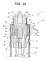
- the ceramic separator 18 is placed so that the rear enters the inside of the filter holding part 51 in the axial direction of the oxygen sensing element 2 and that the front enters the inside of the main cylinder 14 (casing 10), and the leads 20, 21, 28, and 29 ( FIG. 21 ) are inserted axially in the separator lead insertion holes 72.
- the elastic seal member 17 is fitted elastically into the inside of the rear opening 51a of the filter holding part 51, has seal lead insertion holes 91 for inserting the leads 20, 21, 28, and 29, and seals the space between the outer face of the leads 20, 21, 28, and 29 and the inner face of the filter holding part 51.
- the rear end face of the ceramic separator 18 is positioned on the rear from the gas introduction hole 52 in the axial direction and adheres closely to the top face of a gap definition projection 96 formed in the rear end face center of the elastic seal member 17.
- a predetermined gap 98 is formed between the elastic seal member 17 and the ceramic separator 18 by the gap definition projection 96.
- a gap 92 is also formed between the inner peripheral surface of the filter holding part 51 and the outer peripheral surface of the ceramic separator 18. Gas from the gas introduction hole 52 is supplied to the gap 92 and is introduced into the casing 10 through a ventilation communication part 93 formed in the ceramic separator 18.
- the ceramic separator 18 is formed with a through hole 95 for axial ventilation apart from the separator lead insertion holes 72 and is formed on the rear end face with a ventilation groove 94 communicating with the through hole 95 for ventilation at one end and opened to the outer peripheral surface of the ceramic separator 18 at the other end. That is, the through hole 95 for ventilation and the ventilation groove 94 make up the ventilation communication part 93.
- the four separator lead insertion holes 72 for inserting the leads 20, 21, 28, and 29 from the oxygen sensing element 2 and the heating element 3 are made so that the centers of the separator lead insertion holes 72 are positioned on a phantom circumferential path, which will be hereinafter called separator pitch circle, C1.
- the through hole 95 for ventilation is made in an area surrounded by the four separator lead insertion hoses 72 at the center of the ceramic separator 18.
- the ventilation groove 94 is shaped like a cross at a position not interfering with the four separator lead insertion holes 72 on the rear end face of the ceramic separator 18.
- the ventilation groove 94 is formed on the top with a chamfer part 94a on both margins in the width direction.
- seal pitch circle, C2 a phantom circumferential path
- the separator pitch circle C1 (diameter D1) and the seal pitch circle C2 (diameter D2) are set so that the diameter of one is , larger than that of the other.
- the gap definition projection 96 is formed in an area positioned in the inside of the seal lead insertion holes 91 arranged on the seal pitch circle C2.
- the rear end face position of the ceramic separator 18 is set behind the gas introduction hole 52, whereby if water drops, etc., enter the filter assembly 16 through the gas introduction hole 52, they cannot flow into the casing 10 unless the water drops are once drawn into the rear end face of the ceramic separator 18 because the flange-like separator support part 73 blocks the opening of the main cylinder 14.. Therefore, the effect of making it harder to allow water drops to flow into the oxygen sensing element 2 can be accomplished.
- the reference gas flowing in through the gas introduction hole 52 must also be drawn into the rear end face of the ceramic separator 18, but can be introduced- into the casing 10 through the ventilation groove 94 and the through hole 95 for ventilation without a hitch.
- the leads 20, 21, 28, and 29 are inserted into the elastic seal member 17 and the ceramic separator 18 in different pitch circle diameters, thus each lead is always bent between the elastic seal member 17 and the ceramic separator 18.
- the proper gap 98 is formed between the elastic seal member 17 and the ceramic separator 18 and the leads 20, 21, 28, and 29 can be bent in the gap 98 comparatively moderately, so that trouble such that when the oxygen sensor 1 is assembled, etch the leads are strongly bent and damaged or broken becomes hard to occur.
- the elastic seal member 17 and the ceramic separator 18 differ little in pitch circle diameter, they can also be brought into intimate contact with each other without forming the gap 98. If the gap 98 is formed, the tip face of the gap definition projection 96 adheres closely to the elastic seal member 17. In any case, the contact area between the elastic seal member 17 and the ceramic separator 18 overlaps the formation area of the through hole 95 for ventilation. However, even in such a case, the entrance of the through hole 95 for ventilation is not sealed and ventilation of the reference gas to the casing 10 is enabled because the ceramic separator 18 is formed on the top with the ventilation groove 94.
- the flange-like separator support part 73 may be formed with through parts 97 for ventilation axially penetrating the separator support part 73.
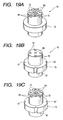
- the through parts 97 for ventilation are grooves (or notches) made at predetermined angle intervals in the outer peripheral surface of the separator support part 73. If the through parts 97 for ventilation are formed, the ventilation groove 94 can be omitted as shown in FIG. 19B .
- FIG. 19B On the other hand, as shown in FIG.
- both the ventilation groove 94 and the through parts 97 for ventilation may be formed, in which case two ventilation passages of the ventilation groove 94 and the through hole 95 for ventilation and the through parts 97 for ventilation are formed, thus ventilation of the reference gas to the casing 10 is enabled more reliably.
- FIG. 20 shows an example of fitting the ceramic separator 18 into the oxygen sensor 1.
- the gap definition projection 96 of the elastic steal member 17 can also be formed like a continuous or intermittent convex stripe along the periphery of the front end face of the elastic seal member 17, as shown in FIG. 23C and FIG. 25 .
- the diameter D1 of the separator pitch circle C1 is larger than the diameter D2 of the seal pitch circle C2 (namely, D1>D2), but the structure can also be applied to the case where D1 ⁇ D2, and is effective if D1 is small and the gap definition projection 96 contact area cannot sufficiently be provided in the area surrounded by the separator lead insertion holes 72, for example.
- the elastic seal member 17 may be formed in the rear end margin with a flange part 99 projecting outward from the outer peripheral surface of the elastic seal member 17, as shown in FIG. 23B and FIG. 24 .
- the flange part 99 of the elastic seal member 17 abuts the rear end face of the filter holding part 51, whereby the position of the front end face of the elastic' seal member 17 in the filter holding part 51 is defined.
- the heating element 3 normally is a ceramic heater; it is constituted by a heating section 42 made up of a ceramic rod 45 consisting essentially of alumina, for example, as a core and a resistance line part (resistance pattern) 41 ( FIG. 29 ) shaped like meandering, for example, on the surface of the ceramic rod 45, as shown in FIGs. 28A and 28B . It is provided by printing a predetermined pattern of resistance paste on a sheet-like external layer ceramic part 43 ( FIG. 29 ) and winding the ceramic part 43 around the ceramic rod 45, then calcining. The ceramic rod 45 projects slightly from the tip of the external layer ceramic part 43 and the resistance pattern 41 is energized for generating heat through the leads 28 and 29 ( FIG. 21 ) extending from the heater terminal parts 40 ( FIG. 1 , etc.,).
- the heating part 42 is one-sided to the tip of the heating element 3 and generates heat locally at the tip.
- a center axis 01 in the proximity of the heating part 42 of the heating element 3 is offset by a given amount 8 so that it is one-sided relative to a center axis 02 of the oxygen sensing element 2, so that the tip surface of the heating part 42 of the heating element 3 is in contact with a hollow part inner wall 2a of the oxygen sensing element 2, which will be hereinafter also called element inner wall 2a, in a state in which it is pressed against the wall 2a at predetermined face pressure.
- the contact position is a position one-sided slightly to the intermediate side from the tip of the closed side of the oxygen sensing element 2 and more preferably a position almost corresponding to the gas permeation port 12 of the protector 11.
- the heating element 3 is placed so that the whole of the portion of the center axis 01 positioned in the hollow part fits in any of the four areas. More specifically, also as shown in FIGs.
- the heating element 3 is placed so that the center axis 01 becomes almost parallel with the center axis 02 of the hollow part, whereby the heating element 3 is constituted by the heating part 42 having a side parallel with the hollow part inner wall 2a of the oxygen sensing element 2.
- the ceramic separator 18 is designed as follows: As shown in FIG. 3 , the ceramic separator 18 is formed with a heating element end housing hole 102 opened in the front end face of the ceramic separator 18 with a bottom 102a positioned in an axial intermediate part of the ceramic separator 18. The whole length of the oxygen sensor 1 can be shortened by housing the rear end part of the heating element 3 in the heating element end housing hole 102. Specifically, as shown in FIGs. 21A to 21B , the heating element end housing hole 102 is formed by cutting away the center of the ceramic separator 18 so as to overlap the separator lead insertion holes 72 from the inside and has an inner diameter set larger than the outer diameter of the heating element 3.
- the heating element 3 is offset as described above, the rear end part thereof is offset relative to the axis of the ceramic separator 18. Since the heating element end housing hole 102 for housing the rear end part of the heating element 3 has the inner diameter set larger than the outer diameter of the heating element 3, a diametrical move of the rear end part as the heating element 3 is offset is allowed within a given limit. That is, if the heating element 3 is offset,-the rear end part thereof is prevented from interfering with the inner wall of the ceramic separator 18 and the offset amount can be set comparatively flexibly.
- the separator lead insertion holes 72 are placed on the separator pitch circle C1 as described above and as shown in FIG. 21B , the inner diameter d1 of the heating element end housing hole 102 is set smaller than the diameter d2 of the separator pitch circle (namely, d1 ⁇ d2). That is, the portion of the ceramic separator 18 positioned between the adjacent separator lead insertion holes 72 functions as a partition wall 103 for separating the leads 20, 21, 28, 29; as the heating element end housing hole 102 is made, the partition wall 103 is cut away from the inside. If d1 ⁇ d2, the diametrical length of the partition wall 103 becomes too short and the separation effect of the leads 20, 21, 28, 29 may be degraded, leading to a short circuit, etc.
- the ratio between the diameter d2 of the pitch circle C1 of the lead insertion holes 72 and the outer diameter D of the end of the heating element 3, d2/D is adjusted in the range of 1.7 to 2.8. If d2/D becomes less than 1.7, a sufficient offset amount of the heating element 3. cannot be provided, resulting in an insufficient lateral strike state of the heating element 3; a sufficient effect of shortening the sensor start-up time may be unable to be expected. If d2/D exceeds 2.8, the leads 20, 21, 28, 29 are too bent and damage, etc., to the leads easily occurs. It is advisable to set the ratio between depth h and inner diameter d1 of the heating element end housing hole 102, h/d1, to 1.2 or less.
- the depth h of the housing hole becomes too large relative to the diameter d1 and a sufficient inclination amount of the heating element 3, namely, a sufficient offset amount cannot be provided; a sufficient effect of shortening the sensor start-up time may be unable to be expected.
- the terminal metal shell 23 ( FIG. 1 ) that serves the function of offsetting the center axis 01 of the heating element 3 from the center axis 02 of the hollow part of the oxygen sensing element 2 in the above-described positional relationship and elastically pressing the heating part 42 against the element inner wall 2a.
- the terminal metal shell 23 plays the following three roles: First, electric connection to the lead 20 as an output terminal of the electrode layer 2c inside the oxygen sensing element 2; second, fitting of the heating element 3 to the inside of the oxygen sensing element 2 (function similar to the conventional function); and third, elastically pressing the tip of the heating element 3 againt the element inner wall 2a in a lateral strike structure.
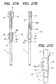
- FIGS. 26A and 26B show a discrete state of the terminal metal shell 23 and FIGs. 27A to 27C show a state in which the terminal metal shell 23 is fitted into the heating element 3.
- a heating element grip part 27 is formed at the tip of the heating element 3 relative to the internal electrode connection part 26, namely, the side close to the heating part 42.
- the heating element grip part 27 has a transverse section shaped like a C letter surrounding the heating element 3.
- the heating element grip part 27 has an inner diameter a little smaller than the outer diameter of the heating element 3.
- the diameter of the heating element grip part 27 is elastically enlarged for gripping the heating element 3 by a friction force.
- the heating element grip part 27 is disposed only at one place on one side of the internal electrode connection part 26.
- the internal electrode connection part 26 is formed so as to surround the heating element 3 by bending like a cylinder, a plate-like portion formed with contact parts 26a like saw teeth in both left and right margins. It positions the heating element 3 axially with respect to the hollow part by the friction force between the outer peripheral surface and the hollow part inner wall 2a of the oxygen sensing element 2 and comes in contact with the inner electrode layer 2c ( FIG. 2 ) at the tips of the contact parts 26a. A predetermined gap is formed between the internal electrode connection part 26 and the heating element 3.
- the left and right contact parts 26a have portions corresponding to the crests and troughs of the saw teeth in offset relation on the left and the right.
- each of the contact parts 26a like saw teeth is set slightly large, whereby when the plate-like portion is bent like a cylinder to form the internal electrode connection part 26, the effect of increasing the width in the bending direction for facilitating working is also accomplished.
- a heating element insertion guide part 100 is formed in the margin far from the tip of the oxygen sensing element 2 in the axial direction of the heating element grip part 27, namely, the front margin.
- the heating element grip part 27 is formed with a slit 101 from one margin to an opposite margin in the axial direction and the heating element insertion guide part 100 is formed like a taper by cutting away both side portions of the slit 101 slantingly toward one margin from an intermediate position of the slit.
- the heating element 3 can be fitted into the terminal metal shell 23 by inserting the heating element 3 into the heating element grip part 27 of the terminal metal shell 23 from the tip. It is pushed into the heating element grip part 27 while widening the heating element grip part 27 diametrically outward from the opening. At this time, the heating element 3 may be unable to be inserted smoothly because the tip margin of the heating element 3 is caught in the end margin of the grip part 27. Particularly, if the slit 101 as described above is formed so that the grip part 27 can be elastically deformed diametrically, the heating element 3 is easily caught in the margin of the slit 101.
- the heating element insertion guide part 100 may be omitted.
- the internal electrode connection part 26 is formed with a positioning projection part 50 projecting from the inner face and abutting the outer peripheral surface of the heating element 3 at a position corresponding to a coupling part 30 of the heating element grip part 27 to the internal electrode connection part 26 in the proximity of the end on the opposed side to the side where the heating element grip part 27 is coupled.
- the positioning projection part 50 is formed, for example, by denting the wall of the internal electrode connection part 26 inward by press working, etc., for positioning the heating element 3 in offset relation to the center axis 02 of the hollow part of the oxygen sensing element 2 as described above.
- the hollow part inner wall 2a of the oxygen sensing element 2 is given a slight taper with the bottom shrunk in diameter for the purpose of enhancing the releasability at the molding time, etc., when it is manufactured by molding and calcining solid electrolyte powder.
- the heating element 3 is placed so that the center axis 01 thereof becomes almost parallel with the center axis 02 of the oxygen sensing element 2, as shown in FIGs . 28A and 28B , etc.
- the gap amount at the formation position of the positioning projection part 50 is defined to be a predetermined value, whereby the positioning projection part 50 satisfies the positional relationship wherein the heating element 3 comes in contact with the hollow part inner wall 2a in the proximity of the heating part 42 and the two center axes 01 and 02 become almost parallel with each other.
- the terminal metal shell 23 is fixed to the heating element 3 and then their assembly is inserted into the oxygen sensing element 2.
- the radial coupling position relationship of the heating element grip part 27 to the internal electrode connection part 26 is defined so that the heating element grip part 27 and the positioning projection part 50 hold the center axis 01 of the heating element 3 with the heating part 42 a little inclined so as to be away from the center axis 02 of the hollow part of the oxygen sensing element 2, whereby when the assembly is inserted, the tip of the heating element 3 is inserted into the element inner wall 2a while sliding in elastic contact with the element inner wall 2a and as indicated by arrows in FIG.
- the heating element 3 is attached to the oxygen sensing element 2 while the inclination state is corrected in the direction in which the center axis 01 of the heating element 3 becomes parallel with the center axis 02 of the hollow part.
- the coupling part 30 between the heating element grip part 27 to the internal electrode connection part 26 is formed in a narrow shape by forming a U-shape notch in the circumferential direction from both sides.
- the coupling part 30 becomes elastically deformed inward and presses the heating part 42 of the heating element 3 against the hollow part inner wall 2a of the oxygen sensing element 2 by an elastic restoration force, producing a lateral strike form as shown in FIG.1 .
- the coupling part 30 also plays a roll in absorbing and buffering the bend force given to the heating element 3 via the heating element grip part 27 and the positioning projection part 50 in the insertion step for preventing damage, etc., to the heating element 3.
- the elastic force can be adjusted by adjusting the width of the narrow part.
- the narrow width of the coupling part 30 is set properly, whereby the elastic force can be adjusted to a proper value and in the lateral strike structure of the heating element 3 in FIG. 1 , the elastic press force against the element inner wall 2a can be provided as a necessary sufficient value.
- a slit-like part 44 parallel with the axial direction occurs at one point of the outer periphery of the heating element 3 as a joint gap when the external layer ceramic part 43 of the heating element 3 is wound around the ceramic rod 45, the resistance pattern 41 does not exist in the proximity of the slit-like part 44, and a heating sparse portion results.
- the hollow part inner wall 2a of the oxygen sensing element 2 is shaped like a taper.
- the ratio of ⁇ D to the outer diameter DB of the heating element 3, ⁇ D/DB, is set to 0.13 or less, preferably 0.10 or less.
- FIG. 28B shows an example of a structure in which the center axis 01 of the heating element 3 is concentric with the center axis 02 of the oxygen sensing element 2.
- the center axis 01 of the heating element 3 is offset by distance 6 from the center axis 02 of the oxygen sensing element 2 with the center axis 01 of the heating element 3 almost parallel with the center axis 02 of the oxygen sensing element 2 and the tip surface of the heating part 42 is pressed against the element inner wall 2a from side as a lateral strike structure.
- the gap between the heating element 3 and the oxygen sensing element 2 is drawn bombastically; when the inner diameter of the element inner wall 2a is 2.8-3.2 mm and the outer diameter of the heating element 3 is 2.43-2.63 mm, it is advisable to set the offset amount ⁇ to about 0.085-0.385 mm, for example, to provide the lateral strike structure reliably without producing an excessive press force between the heating element 3 and the oxygen sensing element 2.
- the heating part 42 in FIG. 28A is one-sided to the narrow area on the tip side of the heating element 3, as described above.
- Such a lateral strike structure of the heating element 3 against the element inner wall 2a is adopted; whereby heat generated in the heating part 42 is transmitted promptly to the oxygen sensing element 2 by heat conduction based on the above-mentioned contact for heating the oxygen sensing element 2 and the oxygen sensing element 2 its also heated by heat radiation of the locally heated portion in the proximity of the contact part.
- the synergistic heat transmission of the heat conduction and the heat radiation heats the oxygen sensing element 2 rapidly, shortening the rise time to activation temperature.
- the oxygen sensing element 2 is heated locally by the heating part 42 placed in the lateral strike state against the element inner wall 2a.
- the sensor start-up time is maintained to a similar degree to that of the sensor of the structure shown in FIG. 28B or is shortened.
- the following is possible as the factor: For a sufficient oxygen concentration cell electromotive force to occur in the oxygen sensing element 2 formed of an oxygen ion conductive solid electrolyte, it is necessary to sufficiently raise catalyst activity of the electrode layers 2b and 2c to an oxygen molecule dissociation or rebonding reaction as well as to sufficiently lessen the electric resistance value of the oxygen sensing element 2.
- the detection output level of the sensor is determined by tradeoffs of the electric resistance value of the oxygen sensing element 2 and the catalyst activity of the electrode layers 2b and 2c.
- the heating element 3 is placed so that the center axis 01 of the heating element 3 becomes almost parallel with the center axis 02 of the oxygen sensing element 2, whereby the side of the heating part 42 becomes almost parallel with the hollow part inner wall 2a of the oxygen sensing element 2 and the walls of the oxygen sensing element 2 can be heated more uniformly by the heating part 42 and in turn the effect of shortening the oxygen sensor activation time is enhanced furthermore.
- the heating element grip part 27 is coupled only to the side of the internal electrode connection part 26 near to the heating part 42 of the heating element 3, thus the length of the terminal metal shell 23 in the axial direction of the heating element 3 becomes short and in turn the oxygen sensor 1 is shortened in the axial length and is made compact. Since the heating element 3 is gripped by one grip part 27, when the heating element 3 with the terminal metal shell 23 attached is inserted into the hollow part of the oxygen sensing element 2 for assembling the oxygen sensor 1, an excessive lateral force via the terminal metal shell 23 becomes hard to act on the heating element 3 and damage, etc., to the heating element 3 at the assembling time can be prevented, as described above.
- two heating element grip parts 27a and 27b can also be coupled to both axial sides of the internal electrode connection part 26 via coupling parts 29 and 30.
- the positioning projection part 50 may be formed in either of the heating element grip parts 27a and 27b. In this case, the inner diameter of the heating element grip part 27a, 27b needs to be preset largely considering the projection amount of the positioning projection part 50.
- the positioning projection part 50 is formed in the heating element grip part 27a far from the heating part 42.
- the positioning projection part 50 is formed in the heating element grip part 27b near to the heating part 42.
- the heating part 42 of the heating element 3 abuts the hollow part inner wall 2a of the oxygen sensing element 2 on the opposite side to the side where the coupling part 29 or 30 is positioned, whereby the heating element 3 is inclined to the hollow part inner wall 2a a little largely and the center axis 01 of the heating element 3 crosses the center axis 02 of the hollow part at a predetermined inclination ⁇ , as shown in FIG. 33 .
- the gap between the heating element 3 and the oxygen sensing element 2 and the inclination ⁇ are drawn bombastically.
- the inner diameter of the element inner wall 2a is 2.8-3.2 mm and the outer diameter of the heating element 3 is 2.43-2.63 mm
- the terminal metal shell 23 is constituted by the internal electrode connection part 26 formed almost as in FIG. 1 .
- the internal electrode connection part 26 is formed on one side with first heating element grip part 27a similar to that described above and formed on the other side with second heating element grip part 27b.
- the pair of the heating element grip parts 27a and 27b is coupled to the internal electrode connection part 26 so that the center axes of the heating element grip parts 27a and 27b are positioned on a common axis 010 offset from and almost parallel with center axis 011 of the hollow part of the oxygen sensing element 2.
- the first heating element grip part 27a and the second heating element grip part 27b are connected integrally to the periphery on the same side in the diametric direction of the heating element 3 by the first and second coupling parts 29 and 30 of narrow parts to the corresponding ends of the internal electrode connection part 26.
- the coupling parts 29 and 30 are bent inward in the diametric direction of the internal electrode connection part 26 to form stepped parts and the bend amount is adjusted, whereby the center axis 010 of the heating element grip parts 27a and 27b is offset by a predetermined offset amount d (as described later) in the opposite direction to the formation side of the coupling parts 29 and 30 almost in parallel with the center axis 011 of the hollow part of the oxygen sensing element 2.
- the heating element 3 can be held on the two grip parts 27a and 27b more stably.
- the terminal metal shell 23 as described above can be manufactured by bending a plate-like metal member 123 shaped as shown in FIG. 36A , for example. That is, as shown in FIG. 36A , the plate-like metal member 123 is constituted by three plate-like parts 127a, 126, and 127b integrated by connection parts 129 and 130 to become the coupling parts 29 and 30 in the intermediate part in the width direction. As shown in FIG. 36B to 36D , the portions projecting on both sides of the connection parts 129 and 130 are bent like a cylinder in the width direction, thereby forming first heating element grip part 27a, internal electrode connection part 26a, and second heating element grip part 27b. As shown in FIG. 36E , the coupling parts 29 and 30 are bent like stepped forms so that the center axis 010 of the heating element grip parts 27a and 27b is placed at a predetermined position.
- both margins in the width direction of the plate-like parts (first plate-like parts) 127a and 127b to become the heating element grip parts 27a and 27b are bent and opposed to each other to form slit 101 and the end part of one of the margins is cut away slantingly to form the heating element insertion guide part 100.
- first heating element grip part 27a and second heating element grip part 27b are formed as in the structure in FIG. 35A and 35B , but the second heating element grip part 27b has the center axis O11 offset by distance d from the center axis O10 of the first heating element grip part 27a, as shown in FIG. 38B .
- first heating element grip part 27a and the second heating element grip part 27b are connected integrally to the periphery on the same side in the diametric direction of the heating element 3 by the first and second coupling parts 29 and 30 of narrow parts to the corresponding ends of the internal electrode connection part 26.-
- the first and second coupling parts 29 and 30 are bent inward in the diametric direction of the internal electrode connection part 26 to form stepped parts and the bend amount is adjusted, whereby the offset amount d between the center axes O10 and O11 of the first heating element grip part 27a and the second heating element grip part 27b is adjusted.
- the heating element 3 is held in an inclination state by the two grip parts 27a and 27b offset from each other and is pressed against the element inner wall 2a, so that it can be held in the inclination state more stably and the lateral strike effect of the heating element 3 is accomplished more reliably.
- the offset amount d between the center axes 010 and 011 of the first heating element grip part 27a and the second heating element grip part 27b can be set as follows: As shown bombastically in FIG. 39 for easy understanding, for example, when the inner diameter of the element inner wall 2a is 2.8-3.2 mm and the outer diameter of the heating element 3 is 2.43-2.63 mm, it is advisable to set the angle between the center axis 01 of the heating element 3 and the center axis 02 of the hollow part of the-oxygen sensing element 2, 6, to about 0.1°-0.5° as descried above.
- d may be set so that 0.0017L ⁇ d ⁇ 0.0087L.
- the two heating element grip parts 27a and 27b are formed each with heating element insertion guide part 100. That is, since the two grip parts 27a and 27b are provided and moreover are formed in offset relation from each other to hold the heating element 3 in the inclination state, the heating element 3 attempts to enter the lower grip part 27b in the offset state after it is inserted into the upper grip part 27a. Thus, the above-described problem of catching the heating element in the grip part easily occurs particularly in the lower grip part 27b. Then, the heating element insertion guide parts 100 are formed as described above, whereby the heating element 3 can be smoothly fitted into the terminal metal shell 23 also in the structure. Since the above-described problem of catching the heating element in the grip part occurs less in the upper grip part 27a than the lower grip part 27b, only the lower grip part 27b may be formed with the heating element insertion guide part 100.
- heating element grip part 27 In a structure shown in FIG. 40 , only one heating element grip part 27 is provided for they internal electrode connection part 26 as in the structure in FIG. 1 , but the positioning projection part 50 its not formed unlike the structure in FIG. 1 . According to the structure in FIG. 40 , the heating element 3 is gripped by the one grip part 27 with some motion freedom in the direction crossing the axis.
- the heating element 3 is inserted into the hollow part of the oxygen sensing element 2 together with the terminal metal shell 23, as the tip of the heating element 3 comes in contact with the inner wall of the oxygen sensing element 2, the heating element 3 is positioned in parallel with the inner wall accordingly and a larger effect of shortening the oxygen sensor activation time can be expected
- ⁇ D or ⁇ D/DB is adjusted in the above-described range, whereby the tip of the heating element 3 becomes more easily parallel with the inner wall of the hollow part of the oxygen sensing element 2 and the effect of shortening the oxygen sensor 1 activation time can be enhance furthermore.
- the length of the terminal metal shell 23 in the axial direction of the heating element can be shortened and in turn the length of the oxygen sensor in the axial direction of the heating element can be shortened for making the oxygen sensor compact.
- the heating element grip part 27 is connected to the axial rear end of the internal electrode connection part 26 and a guide part 128 is connected to the front end.
- the guide part 128 has a transverse section shaped almost like a half circle and is inclined inward by a predetermined angle relative to the center axis of the terminal metal shell 23, more particularly, the center axis of the heating element grip part 27 and the internal electrode connection part 26, so that it presses the heating element 3 against the element inner wall 2a in a direction perpendicular to the axial direction of the heating element 3.
- An oxygen sensor of the invention is constituted by an oxygen sensor comprising:
- the casing and the filter assembly can be formed as separate bodies and the filter assembly can be placed on the rear of the casing, then the coupling part is formed, thereby coupling the casing and the filter assembly.
- the oxygen sensor has the feature that the ventilation structure containing the filter is formed as the filter assembly separate from the casing and is coupled to the casing.
- the filter assembly is constituted by a filter holding part being placed coaxially and: coupled with the rear of the casing so that the inside of the filter holding part communicates with the inside of the casing and formed in a wall with one or more gas introduction holes, a filter being placed so as to block the gas introduction hole or holes on the outside of the filter holding part for rejecting permeation of liquid and allowing gas to pass through, and an auxiliary filter holding part being formed like a cylinder placed on the outside of the filter and formed in a wall with one or more auxiliary gas introduction holes for sandwiching the filter between the auxiliary filter holding part and the filter holding part.
- outside air is introduced into the casing through the auxiliary gas introduction hole, the filter, and the gas introduction hole.
- the filter can be held reliably by the auxiliary filter holding part and the filter holding part and the filter is also easily fitted into the filter holding part.
- the filter is formed like a cylinder, it is fitted into the outside of the filter holding part, further the auxiliary filter holding part is fitted from the outside, and the holding part coupling part for coupling the filter holding part and the auxiliary filter holding part may be formed at a position not interfering with the gas introduction hole or the auxiliary gas introduction hole.
- a plurality of the gas introduction holes and a plurality of the auxiliary gas introduction holes can be made with a predetermined spacing along a circumferential direction in positional relationship corresponding to each other in an axial intermediate part in the filter holding part and the auxiliary filter holding part, whereby outside air can be uniformly introduced into the casing from the filter assembly side.
- cylindrical filter can be placed on the outside of the filter holding part so as to surround the filter holding part in the circumferential direction and the auxiliary filter holding part can be formed with an annular filter crimp part along the circumferential direction of the auxiliary filter holding part as a holding part coupling part by crimping the auxiliary filter holding part toward the filter holding part with the filter between.
- Assembling of the filter assembly is furthermore facilitated by making the holding part coupling part the annular filter crimp part.
- the annular filter crimp part can be formed on both sides sandwiching axially the gas introduction hole and auxiliary gas introduction hole row.
- the filter margin is sandwiched between the auxiliary filter holding part and the filter holding part, whereby a passage bypassing the filter margin from the auxiliary gas introduction hole and leading to the gas introduction hole in the filter holding part is hard to form and the possibility that water, etc., will pass through the passage and leak into the filter holding part and in turn the casing is also lessened.
- the filter is shaped like a cylinder as described above and is placed along the outer periphery of the filter holding part, the filter crimp part can be formed along the circumferential direction on the rear end of the auxiliary filter holding part.
- a filter check part to visually check the filter positioned between the auxiliary filter holding part and the filter holding part is formed on the rear end of the auxiliary filter holding part.
- the filter crimp part can also be formed with a filter check exposure part for exposing the filter partially. In doing so, whether or not the filter is normally crimped can also be determined easily in the front end margin of the auxiliary filter holding part.
- the filter assembly can be coupled to the casing by various methods.
- the filter holding part can be placed so as to overlap the casing at the tip of the filter holding part from the outside and an annular assembly coupling crimp part as the coupling part can be formed in the circumferential direction of the filter holding part and the casing by crimping the filter holding part toward the casing in the overlap and can press the inner peripheral surface of the filter holding part against the outer peripheral surface of the casing in hermetic relation. That is, the filter assembly can be easily fitted into the casing by the assembly coupling crimp part.
- An annular weld part (for example, resistance weld part or laser weld part) may be formed in place of or together with the crimp part.
- the filter holding part can have the axial front relative to a stepped part formed in an axial intermediate part of the filter holding part as a first portion and the rear as a second portion so that the second portion is made smaller in diameter than the first portion.
- the gas introduction hole can be made in a wall of the second portion.
- the rear end part of the casing can be inserted into the first portion of the filter holding part to a position at which it abuts directly or indirectly via a member the stepped part.
- the casing overlap is formed in the first portion and the assembly coupling crimp part (or weld part) can be formed here.
- the stepped part can be used to easily positioning axially the filter holding part to the casing. If a gas introduction hole is made in the small-diameter second portion and the filter and the auxiliary filter holding part are fitted into the hole from the outside, when the filter and the filter holding part are fitted in order from the upper side, for example, in a state in which the filter holding part is upright with the second portion up, the filter and the filter holding part can be stricken against the stepped part and stopped. Thus, assembling of the filter assembly is facilitated furthermore.
- the inner diameter of the auxiliary filter holding part needs to be preset smaller than the outer diameter of the first portion.
- the oxygen sensor can further include a ceramic separator formed with a plurality of lead insertion holes axially penetrating the ceramic separator for inserting leads from the oxygen sensing element.
- the ceramic separator can be placed so that the rear thereof enters the inside of the filter holding part in the axial direction of the oxygen sensing element and the front enters the inside of the casing. A part of the ceramic separator is entered in the inside, of the filter holding part, whereby free space formed in the filter holding part on the rear of the ceramic separator becomes small and in turn the axial length of the oxygen sensor can be shortened accordingly for making the whole oxygen sensor compact.
- the ceramic separator can be formed with a separator support part projecting from an outer peripheral surface of the ceramic separator, for example, like a flange at an intermediate position in the axial direction thereof.
- the ceramic separator can be placed so as to abut directly or indirectly via a member the rear end face of the casing in the separator support part in a state in which a portion positioned ahead the separator support part is entered in the rear end inside of the casing, and can be placed in a state in which a portion positioned behind the separator support part is projected to the outside of the casing.
- the filter holding part can be placed so as to allow the projection of the ceramic separator to enter the inside of the second portion and cover it and abut directly or indirectly via a member the separator support part in the stepped part from an opposite side to the casing. That is, the separator support part is sandwiched between the end face of the casing and the stepped part of the filter holding part; whereby the ceramic separator can be supported more stably in the casting and in turn trouble such as breaking or chipping of the ceramic separator because of a rattle becomes hard to occur.
- the ceramic separator can be formed with a ventilation communication part axially penetrating the ceramic separator from the rear end face to the front end face thereof for introducing outside air flowing in through the gas introduction hole into the inside of the casing, whereby outside air as the reference gas can be introduced into the oxygen sensing element reliably and promptly.
- a ventilation communication part axially penetrating the ceramic separator from the rear end face to the front end face thereof for introducing outside air flowing in through the gas introduction hole into the inside of the casing, whereby outside air as the reference gas can be introduced into the oxygen sensing element reliably and promptly.
- the rear end face of the ceramic separator can be positioned behind the gas introduction hole. In doing so, if water drops are entered, they must be bypassed to the rear end face of the ceramic separator to leak into the casing from the ventilation communication part, thus the possibility that the water drops will leak into the oxygen sensing element can be more lessened.
Landscapes
- Chemical & Material Sciences (AREA)
- Life Sciences & Earth Sciences (AREA)
- Health & Medical Sciences (AREA)
- Physics & Mathematics (AREA)
- Chemical Kinetics & Catalysis (AREA)
- Electrochemistry (AREA)
- Molecular Biology (AREA)
- Analytical Chemistry (AREA)
- Biochemistry (AREA)
- General Health & Medical Sciences (AREA)
- General Physics & Mathematics (AREA)
- Immunology (AREA)
- Pathology (AREA)
- Measuring Oxygen Concentration In Cells (AREA)
Claims (11)
- Sauerstoffsensor, umfassend:ein Sauerstoffmesselement (2), welches wie eine hohle Achse mit einer geschlossenen Spitze geformt ist, wobei die Seite in Richtung der Spitze in der axialen Richtung des Sauerstoffmesselementes hier als die Vorderseite definiert ist, und die Seite in Richtung der gegenüberliegenden Richtung hier als die Hinterseite definiert ist;ein zylindrisches Gehäuse (10) zur Aufnahme des Sauerstoffmesselementes (2);ein Filteraufbau (16), welcher im Wesentlichen koaxial in dem Gehäuse (10) als ein von dem Gehäuse (10) getrennter zylindrischer Körper angeordnet ist und mit dem Gehäuse (10) von der Hinterseite aus verbunden ist, so dass sich Anschlussdrähte (20, 21, 28, 29) von dem Sauerstoffmesselement (2) zu der hinteren Außenseite des Filteraufbaus (16) erstreckten können; undein Verbindungsteil um den Filteraufbau (16) und das Gehäuse (10) zu verbinden, wobei der Filteraufbau (16) umfasst:dadurch gekennzeichnet, dass er ein Filterüberprüfungsteil umfasst, um optisch die poröse Faserstruktur des Filters (53) zu überprüfen, welcher zwischen dem Hilfsfilterhalteteil (54) und dem Filterhalteteil (51) angeordnet ist, gebildet an dem hinteren Ende des Hilfsfilterhalteteils (54) als die Öffnung einer kreisförmigen Spalte zwischen dem Hilfsfilterhalteteil (54) und dem Filterhalteteil (51).einen Filterhalteteil (51), welcher eine zylindrische Form aufweist, und im Wesentlichen koaxial mit dem Gehäuse (10) von einer Hinterseite des Gehäuses (10) verbunden ist, welcher eine innere Kommunikation mit einer Innenseite des Gehäuses (10) aufweist und wobei in einer Wand ein oder mehrere Gaseinführlöcher (52) ausgebildet sind;einen Filter (53), welcher aus einer porösen Faserstruktur hergestellt ist, welcher angeordnet ist, um so das Gaseinführloch oder die Löcher (52) in dem Filterhalteteil (51) von einer äußeren Seitenfläche zu blockieren, um das Eindringen von Flüssigkeit zu verhindern und zu ermöglichen, dass Gas hindurchgeführt wird; undeinenen Hilfsfilterhalteteil (54) um den Filter (53) an dem Filterhalteteil (51) zu fixieren, um zu gestatten, dass Außenluft in das Gehäuse (10) durch den Filter (53) und das Gaseinführloch (52) eingeführt wird, wobei der Filter (53) wie ein Zylinder entlang des äußeren Umfangs eines Bereichs des Filterhalteteils (51) geformt ist;ein Filtercrimpteil (56), gebildet entlang der Umfangsrichtung an dem hinteren Ende des Hilfsfilterhalteteils (54); und
- Sauerstoffsensor nach Anspruch 1, wobei das Gehäuse (10) und der Filteraufbau (16) als getrennte Körper gebildet sind und wobei der Filteraufbau (16) an der Hinterseite des Gehäuses (10) angeordnet ist, anschließend das Verbindungsteil gebildet wird, wodurch das Gehäuse (10) und der Filteraufbau (16) verbunden werden.
- Sauerstoffsensor nach Anspruch 1 oder 2, wobei der Filteraufbau (16) umfasst:den Filterhalteteil (51), welcher koaxial angeordnet ist und mit dem hinteren Ende des Gehäuses (10) verbunden ist, so dass ein Inneres des Filterhalteteils (51) in Verbindung mit einem inneren des Gehäuses (10) steht und in einer Wand mit einer oder mehreren Gaseinführlöchern (52) ausgebildet ist, undwobei der Filterhalteteil (54) wie ein Zylinder gebildet ist, angeordnet an einer Außenseite des Filters (53) und wobei in einer Wand ein oder mehrere Hilfsgaseinführlöcher (55) ausgebildet sind, um den Filter (53) zwischen dem Hilfsfilterhalteteil (54) und dem Filterhalteteil (51) anzuordnen, so dass Außenluft in das Gehäuse (10) durch das Hilfsgaseinführloch (55), den Filter (53) und das Gaseinführloch (52) eindringen kann.
- Sauerstoffsensor nach Anspruch 3, wobei eine Vielzahl der Gaseinführlöcher (52) und eine Vielzahl der Hilfsgaseinführlöcher (55) mit einem vorbestimmten Abstand entlang einer Umfangsrichtung voneinander beabstandet sind in einer positionellen Beziehung entsprechend einander in einem axialen Mittelteil des Filterhalteteils (51) und des Hilfsfilterhalteteils (54);
der Filter (53) angeordnet ist, um so den Filterhalteteil (51) in der Umfangsrichtung zu umgeben; und
der Hilfsfilterhalteteil (54) mit einem kreisförmigen Filtercrimpteil (56, 57) entlang der Umfangsrichtung des Hilfsfilterhalteteils (54) ausgebildet ist, in dem der Hilfsfilterhalteteil (54) zu dem Filterhalteteil mit dem Filter gecrimpt wird. - Sauerstoffsensor nach einem der Ansprüche 1 bis 4, wobei der Filterhalteteil (51) so angeordnet ist, dass er das Gehäuse (10) an einer Spitze des Filterhalteteils (51) von einer Außenseite überlappt;
ein kreisförmiges Aufbauverbindungscrimpteil (75) als der Verbindungsteil in einer Umfangsrichtung des Filterhalteteils (51) und des Gehäuses (10) gebildet ist, in dem der Filterhalteteil (51) in Richtung des Gehäuses (10) in der Überlappung gecrimpt wird und eine innere Umfangsfläche des Filterhalteteils (51) gegen eine äußere Umfangsfläche des Gehäuses (10) in einer hermetischen Beziehung presst. - Sauerstoffsensor nach Anspruch 5, wobei der Filterhalteteil (51) eine axiale Vorderseite aufweist, relativ zu einem gestuften Teil (60), welcher in einem axialen Mittelteil des Filterhalteteils (51) als ein erster Bereich (61) ausgebildet ist, und ein hinterer Teil als ein zweiter Bereich (62), so dass der zweite Bereich (62) im Durchmesser kleiner ist, als der erste Bereich (61), wobei das Gaseinführloch (42) in einer Wand des zweiten Bereichs (62) ausgebildet ist; und
das hintere Ende des Gehäuses (10) in den ersten Bereich (61) des Filterhalteteils (51) eingeführt ist, bis zu einer Position, an welcher er direkt oder indirekt über ein Element an den gestuften Teil (60) anstößt und der Aufbauverbindungscrimpteil (75) ist in der Überlappung ausgebildet, welcher in diesem Zustand in dem ersten Bereich (61) auftritt. - Sauerstoffsensor nach Anspruch 6, wobei der Hilfsfilterhalteteil (51) einen kleineren Innendurchmesser als ein Außendurchmesser des ersten Bereichs (61) aufweist.
- Sauerstoffsensor nach einem der Ansprüche 1 bis 9 umfassend einen keramischen Separator (18), welcher so angeordnet ist, dass ein hinteres Ende dessen in das Innere des Filterhalteteils (51) in einer axialen Richtung des Sauerstoffmesselementes (2) eintritt und ein vorderes Ende in das Innere des Gehäuses (10) eintritt und welches mit eintritt und ein vorderes Ende in das Innere des Gehäuses (10) eintritt und welches mix einer Vielzahl von Anschlußdrahteinführlöchern (72) ausgebildet ist, die axial in den keramischen Separator (18) eindringen, um Leitungen von dem Sauerstoffmesselement (2) einzuführen.
- Sauerstoffsensor nach Anspruch 8, wobei der keramische Separator (18) mit einem Separatortrageteil (63) ausgebildet ist, welcher von einer äußeren Umfangsfläche des keramischen Separators (18) an einer mittleren Position in einer axialen Richtung dessen vorsteht;
wobei der keramische Separator (18) so angeordnet ist, dass er direkt oder indirekt über ein Element an die hintere Endfläche des Gehäuses (10) in dem Separatortrageteil (73) anstößt, in einem Zustand, in welchem ein Teil, welcher vor dem Separatortrageteil (53) angeordnet ist, in das hintere Ende im Inneren des Gehäuses (10) eintritt und es in einem Zustand, in welchem ein Teil hinter dem Separatortrageteil (73) angeordnet ist, aus dem Äußeren des Gehäuses (10) hervorsteht; und
wobei der Filterhalteteil (51) so angeordnet ist, dass der Vorsprung des keramischen Separators (18) in das Innere des zweiten Bereichs (62) eindringen kann und diese bedeckt und direkt oder indirekt über ein Element an den Separatortrageteil (73) in dem gestuften Teil (60) von einer gegenüberliegenden Seite des Gehäuses (10) anstößt. - Sauerstoffsensor nach Anspruch 9, wobei der keramische Separator (18) mit einem Ventilationsverbindungsteil (93) ausgebildet ist, welcher axial den keramischen Separator (18) von einer hinteren Endfläche zu der vorderen Endfläche dessen durchdringt, um Außenluft einzuführen, welche durch das Gaseinführloch (52) in das Innere des Gehäuses (10) fließt und die hintere Endfläche ist hinter dem Gaseinführloch (52) angeordnet.
- Sauerstoffsensor nach einem der Ansprüche 1 bis 10, wobei die poröse Filterstruktur des Filters Polytetrafluorethylen umfasst.
Priority Applications (2)
| Application Number | Priority Date | Filing Date | Title |
|---|---|---|---|
| EP04028932A EP1512966B1 (de) | 1997-08-29 | 1998-08-28 | Sauerstoffsensor |
| EP04028933A EP1512967B1 (de) | 1997-08-29 | 1998-08-28 | Sauerstoffsensor |
Applications Claiming Priority (27)
| Application Number | Priority Date | Filing Date | Title |
|---|---|---|---|
| JP249824/97 | 1997-08-29 | ||
| JP24985897 | 1997-08-29 | ||
| JP9249651A JPH1172462A (ja) | 1997-08-29 | 1997-08-29 | 酸素センサ |
| JP24983897A JP3578436B2 (ja) | 1997-08-29 | 1997-08-29 | 酸素センサ |
| JP249825/97 | 1997-08-29 | ||
| JP24983897 | 1997-08-29 | ||
| JP24965197 | 1997-08-29 | ||
| JP9249859A JPH1172470A (ja) | 1997-08-29 | 1997-08-29 | 酸素センサ |
| JP9249652A JPH1172463A (ja) | 1997-08-29 | 1997-08-29 | 酸素センサ |
| JP249652/97 | 1997-08-29 | ||
| JP249858/97 | 1997-08-29 | ||
| JP24982597A JP3869534B2 (ja) | 1997-08-29 | 1997-08-29 | 酸素センサ |
| JP249651/97 | 1997-08-29 | ||
| JP249826/97 | 1997-08-29 | ||
| JP249859/97 | 1997-08-29 | ||
| JP24982597 | 1997-08-29 | ||
| JP24982497 | 1997-08-29 | ||
| JP24986097 | 1997-08-29 | ||
| JP24982697 | 1997-08-29 | ||
| JP24985897A JP3713134B2 (ja) | 1997-08-29 | 1997-08-29 | 酸素センサ |
| JP249838/97 | 1997-08-29 | ||
| JP24982697A JP3713133B2 (ja) | 1997-08-29 | 1997-08-29 | 酸素センサ |
| JP249860/97 | 1997-08-29 | ||
| JP24965297 | 1997-08-29 | ||
| JP24985997 | 1997-08-29 | ||
| JP24986097A JP3660110B2 (ja) | 1997-08-29 | 1997-08-29 | 酸素センサ |
| JP9249824A JPH1172464A (ja) | 1997-08-29 | 1997-08-29 | 酸素センサ |
Related Child Applications (2)
| Application Number | Title | Priority Date | Filing Date |
|---|---|---|---|
| EP04028933A Division EP1512967B1 (de) | 1997-08-29 | 1998-08-28 | Sauerstoffsensor |
| EP04028932A Division EP1512966B1 (de) | 1997-08-29 | 1998-08-28 | Sauerstoffsensor |
Publications (3)
| Publication Number | Publication Date |
|---|---|
| EP0899562A2 EP0899562A2 (de) | 1999-03-03 |
| EP0899562A3 EP0899562A3 (de) | 2001-09-12 |
| EP0899562B1 true EP0899562B1 (de) | 2009-07-29 |
Family
ID=27577675
Family Applications (3)
| Application Number | Title | Priority Date | Filing Date |
|---|---|---|---|
| EP98306913A Expired - Lifetime EP0899562B1 (de) | 1997-08-29 | 1998-08-28 | Sauerstoffsensor |
| EP04028932A Expired - Lifetime EP1512966B1 (de) | 1997-08-29 | 1998-08-28 | Sauerstoffsensor |
| EP04028933A Expired - Lifetime EP1512967B1 (de) | 1997-08-29 | 1998-08-28 | Sauerstoffsensor |
Family Applications After (2)
| Application Number | Title | Priority Date | Filing Date |
|---|---|---|---|
| EP04028932A Expired - Lifetime EP1512966B1 (de) | 1997-08-29 | 1998-08-28 | Sauerstoffsensor |
| EP04028933A Expired - Lifetime EP1512967B1 (de) | 1997-08-29 | 1998-08-28 | Sauerstoffsensor |
Country Status (3)
| Country | Link |
|---|---|
| US (1) | US6395159B2 (de) |
| EP (3) | EP0899562B1 (de) |
| DE (2) | DE69841010D1 (de) |
Families Citing this family (34)
| Publication number | Priority date | Publication date | Assignee | Title |
|---|---|---|---|---|
| EP0918215B1 (de) * | 1997-11-21 | 2004-04-07 | Denso Corporation | Gassensor |
| JP3648381B2 (ja) * | 1998-06-04 | 2005-05-18 | 日本特殊陶業株式会社 | ガスセンサ及びその製造方法 |
| EP0981045B1 (de) * | 1998-08-19 | 2007-12-19 | NGK Spark Plug Co., Ltd. | Gassensor |
| JP3655522B2 (ja) * | 1999-06-11 | 2005-06-02 | 日本特殊陶業株式会社 | 酸素センサ |
| JP3662464B2 (ja) * | 1999-06-23 | 2005-06-22 | 日本特殊陶業株式会社 | 酸素センサ |
| ES2154239B1 (es) * | 1999-08-10 | 2001-10-01 | Union Fenosa Generacion S A | Sonda de oxigeno. |
| JP2001289814A (ja) | 2000-02-01 | 2001-10-19 | Denso Corp | ガスセンサ |
| JP2001330584A (ja) | 2000-03-17 | 2001-11-30 | Denso Corp | ガスセンサ |
| JP4047919B2 (ja) * | 2002-07-19 | 2008-02-13 | 日本特殊陶業株式会社 | センサ、センサの製造方法、セパレータと付勢部材の組立体 |
| JP4172267B2 (ja) | 2002-12-20 | 2008-10-29 | 株式会社デンソー | ガスセンサ |
| DE10327186B4 (de) | 2003-06-17 | 2006-11-30 | Robert Bosch Gmbh | Messfühler |
| EP1507144B1 (de) * | 2003-07-04 | 2018-05-09 | Ngk Spark Plug Co., Ltd | Zylindrischer Gassensor enthaltend eine vibrationsbeständige Schutzkappe |
| US20050109619A1 (en) * | 2003-11-17 | 2005-05-26 | Ngk Spark Plug Co., Ltd. | Gas Sensor |
| EP1544609A1 (de) * | 2003-12-15 | 2005-06-22 | Hitachi, Ltd. | Sauerstoffsensor |
| JP2007093572A (ja) * | 2005-08-29 | 2007-04-12 | Shinko Electric Ind Co Ltd | 固体電解質ガスセンサ |
| JP2007180009A (ja) * | 2005-12-02 | 2007-07-12 | Ngk Spark Plug Co Ltd | 圧着端子及び当該圧着端子を備えたガスセンサ及び前記圧着端子の製造方法 |
| US8721855B2 (en) * | 2005-12-02 | 2014-05-13 | Ngk Spark Plug Co. Ltd. | Crimp contact, crimp contact with an electrical lead, gas sensor including said crimp contact and method for manufacturing said gas sensor |
| US20090050481A1 (en) * | 2007-08-24 | 2009-02-26 | Denso Corporation | Gas sensor with increased durability and reliability |
| US8042380B2 (en) * | 2007-09-14 | 2011-10-25 | Ngk Spark Plug Co., Ltd. | Gas sensor |
| US8022538B2 (en) * | 2008-11-17 | 2011-09-20 | Stats Chippac Ltd. | Base package system for integrated circuit package stacking and method of manufacture thereof |
| US8567231B2 (en) * | 2010-05-24 | 2013-10-29 | Ngk Spark Plug Co., Ltd. | Gas sensor |
| JP5179545B2 (ja) * | 2010-07-06 | 2013-04-10 | 日本特殊陶業株式会社 | ガスセンサ |
| WO2012057786A1 (en) * | 2010-10-29 | 2012-05-03 | Utc Fire & Security Corporation | Oxygen measuring apparatuses |
| CN102416214B (zh) * | 2011-09-15 | 2014-03-05 | 吴江富凯医用卫生用品有限公司 | 婴幼儿用供氧装置的支撑腿连接结构 |
| WO2014182745A2 (en) * | 2013-05-07 | 2014-11-13 | Stoneridge, Inc. | Exhaust gas temperature sensor |
| JP6227447B2 (ja) * | 2014-03-12 | 2017-11-08 | 日本碍子株式会社 | ガスセンサへの保護チューブ装着方法およびガスセンサへの保護チューブ装着装置 |
| JP6535156B2 (ja) * | 2014-03-12 | 2019-06-26 | 日本碍子株式会社 | ガスセンサ |
| JP6981913B2 (ja) * | 2018-04-09 | 2021-12-17 | 日本特殊陶業株式会社 | センサ |
| US20190323986A1 (en) | 2018-04-18 | 2019-10-24 | Delphi Technologies Ip Limited | Gas sensor |
| JP7253568B2 (ja) * | 2019-04-17 | 2023-04-06 | 日本特殊陶業株式会社 | ガスセンサ |
| DE102019205938A1 (de) | 2019-04-25 | 2020-10-29 | Mahle International Gmbh | Fluidleitungssystem zur Führung von Fluid, insbesondere für ein Kraftfahrzeug, sowie Klimagerät für ein Kraftfahrzeug insbesondere ein HVAC-Gerät |
| JP7379102B2 (ja) * | 2019-11-12 | 2023-11-14 | 日本碍子株式会社 | ガスセンサ |
| US11650265B2 (en) * | 2021-03-03 | 2023-05-16 | Honeywell International Inc. | Electric meter having gas sensor for arc detection |
| CN113447612A (zh) * | 2021-05-20 | 2021-09-28 | 浙江集赞电子科技有限公司 | 一种化学实验室便携式智能氧气传感器 |
Family Cites Families (36)
| Publication number | Priority date | Publication date | Assignee | Title |
|---|---|---|---|---|
| US2226849A (en) * | 1936-07-03 | 1940-12-31 | Kingston Products Corp | Electrical connection means |
| US3146519A (en) * | 1961-03-21 | 1964-09-01 | Etc Inc | Method of making electrical connections |
| US3962153A (en) | 1970-05-21 | 1976-06-08 | W. L. Gore & Associates, Inc. | Very highly stretched polytetrafluoroethylene and process therefor |
| CA962021A (en) | 1970-05-21 | 1975-02-04 | Robert W. Gore | Porous products and process therefor |
| US4096227A (en) | 1973-07-03 | 1978-06-20 | W. L. Gore & Associates, Inc. | Process for producing filled porous PTFE products |
| US3871071A (en) * | 1973-09-24 | 1975-03-18 | Thomas & Betts Corp | Method of forming an electrical connection |
| JPS56133653A (en) | 1980-03-25 | 1981-10-19 | Toyota Motor Corp | O2 sensor |
| JPS56168155A (en) * | 1980-05-29 | 1981-12-24 | Nippon Denso Co Ltd | Detector for concentration of oxygen |
| JPS59152825A (ja) | 1983-02-19 | 1984-08-31 | Daikin Ind Ltd | ポリテトラフルオロエチレン半焼成体およびその製法 |
| US4596837A (en) | 1982-02-22 | 1986-06-24 | Daikin Industries Ltd. | Semisintered polytetrafluoroethylene article and production thereof |
| DE3327397A1 (de) * | 1983-07-29 | 1985-02-14 | Robert Bosch Gmbh, 7000 Stuttgart | Gasmessfuehler |
| DE3474352D1 (en) * | 1983-11-10 | 1988-11-03 | Ngk Spark Plug Co | Oxygen sensor |
| US4828516A (en) * | 1983-12-30 | 1989-05-09 | Amp Incorporated | Crimped electrical connection and crimping dies therefore |
| JPS60183857U (ja) * | 1984-05-07 | 1985-12-06 | 株式会社デンソー | 酸素濃度検出器 |
| US4883643A (en) * | 1985-06-20 | 1989-11-28 | Ngk Spark Plug Co., Ltd. | Oxygen sensor protected against contaminants |
| US4786399A (en) | 1987-09-28 | 1988-11-22 | Allied-Signal Inc. | Seal means for isolated grounded O2 sensor |
| US4824550A (en) * | 1987-10-19 | 1989-04-25 | General Motors Corporation | Heated solid electrolyte oxygen sensor and securing element therefor |
| JP2659791B2 (ja) | 1989-03-13 | 1997-09-30 | 日本碍子株式会社 | 防水型酸素センサ |
| US4966560A (en) * | 1989-09-07 | 1990-10-30 | Calcomp Inc. | Coaxial connector plug using a center conductor sleeve and single point crimping |
| JPH0689165B2 (ja) | 1990-01-29 | 1994-11-09 | ダイキン工業株式会社 | ポリテトラフルオロエチレン多孔膜およびその製造方法 |
| JP2792225B2 (ja) | 1990-10-19 | 1998-09-03 | 株式会社デンソー | 酸素センサ |
| US5139639A (en) * | 1991-03-08 | 1992-08-18 | General Motors Corporation | Electrochemical type exhaust gas oxygen sensor |
| US5573650A (en) * | 1993-01-28 | 1996-11-12 | Nippondenso Co., Ltd. | Gas sensor |
| JP2854223B2 (ja) | 1993-09-08 | 1999-02-03 | ジャパンゴアテックス株式会社 | 撥油防水性通気フィルター |
| JPH07196831A (ja) | 1993-12-28 | 1995-08-01 | Japan Gore Tex Inc | ポリテトラフルオロエチレン多孔膜とその製造方法 |
| US5423972A (en) * | 1994-01-18 | 1995-06-13 | General Motors Corporation | Watertight exhaust gas sensor |
| JP3522357B2 (ja) | 1994-09-19 | 2004-04-26 | 日本特殊陶業株式会社 | 酸素センサ |
| JPH08201338A (ja) | 1995-01-23 | 1996-08-09 | Nippondenso Co Ltd | 酸素濃度検出器 |
| JP3221541B2 (ja) | 1995-01-26 | 2001-10-22 | 日本電信電話株式会社 | 光導波路と光ファイバとの接続構造および接続方法 |
| JP3501187B2 (ja) * | 1995-02-08 | 2004-03-02 | 株式会社デンソー | 酸素濃度検出器 |
| JPH08240558A (ja) * | 1995-03-03 | 1996-09-17 | Nippondenso Co Ltd | 酸素濃度検出器 |
| JP3624526B2 (ja) * | 1995-06-07 | 2005-03-02 | 株式会社デンソー | 酸素濃度検出器 |
| JP3624498B2 (ja) * | 1995-10-27 | 2005-03-02 | 株式会社デンソー | 空燃比センサ |
| JP3539031B2 (ja) * | 1996-01-18 | 2004-06-14 | 株式会社デンソー | 空燃比センサ |
| US5874664A (en) | 1996-01-30 | 1999-02-23 | Denso Corporation | Air fuel ratio sensor and method for assembling the same |
| JP3027726B2 (ja) * | 1996-06-05 | 2000-04-04 | 日本特殊陶業株式会社 | ヒータ付き酸素センサ |
-
1998
- 1998-08-28 DE DE69841010T patent/DE69841010D1/de not_active Expired - Lifetime
- 1998-08-28 EP EP98306913A patent/EP0899562B1/de not_active Expired - Lifetime
- 1998-08-28 US US09/143,384 patent/US6395159B2/en not_active Expired - Lifetime
- 1998-08-28 EP EP04028932A patent/EP1512966B1/de not_active Expired - Lifetime
- 1998-08-28 DE DE69838524T patent/DE69838524T2/de not_active Expired - Lifetime
- 1998-08-28 EP EP04028933A patent/EP1512967B1/de not_active Expired - Lifetime
Also Published As
| Publication number | Publication date |
|---|---|
| EP1512966A2 (de) | 2005-03-09 |
| EP1512966B1 (de) | 2007-10-03 |
| EP1512966A3 (de) | 2005-06-29 |
| EP1512967A2 (de) | 2005-03-09 |
| EP0899562A2 (de) | 1999-03-03 |
| US20010054552A1 (en) | 2001-12-27 |
| EP0899562A3 (de) | 2001-09-12 |
| EP1512967B1 (de) | 2012-05-02 |
| DE69838524T2 (de) | 2008-07-03 |
| DE69841010D1 (de) | 2009-09-10 |
| DE69838524D1 (de) | 2007-11-15 |
| EP1512967A3 (de) | 2005-06-29 |
| US6395159B2 (en) | 2002-05-28 |
Similar Documents
| Publication | Publication Date | Title |
|---|---|---|
| EP0899562B1 (de) | Sauerstoffsensor | |
| US8016990B2 (en) | Protective covers for gas sensor, gas sensor and gas sensor manufacturing method | |
| EP1688737B1 (de) | Kompakte Struktur eines Gassensors und seine Produktionsmethode | |
| EP0962766B1 (de) | Gassensor und Methode zu dessen Herstellung | |
| US6548023B1 (en) | Gas sensor | |
| JP5529070B2 (ja) | ガスセンサ | |
| JP4706687B2 (ja) | ガスセンサ及びその製造方法 | |
| JP4325040B2 (ja) | ガスセンサ及びその製造方法 | |
| JP3660110B2 (ja) | 酸素センサ | |
| US11768168B2 (en) | Sensor and method for manufacturing same | |
| JPH1172462A (ja) | 酸素センサ | |
| JPH1172464A (ja) | 酸素センサ | |
| US12320776B2 (en) | Gas sensor | |
| JP3713134B2 (ja) | 酸素センサ | |
| JP3713133B2 (ja) | 酸素センサ | |
| JP3578436B2 (ja) | 酸素センサ | |
| JP3705907B2 (ja) | 酸素センサ | |
| JP3705907B6 (ja) | 酸素センサ | |
| JP3950523B2 (ja) | ヒータ付き酸素センサ | |
| JP3869534B2 (ja) | 酸素センサ | |
| JPH1172463A (ja) | 酸素センサ | |
| JP2000193630A (ja) | ガスセンサ及びガスセンサの製造方法 | |
| JP2000046786A (ja) | ガスセンサ |
Legal Events
| Date | Code | Title | Description |
|---|---|---|---|
| PUAI | Public reference made under article 153(3) epc to a published international application that has entered the european phase |
Free format text: ORIGINAL CODE: 0009012 |
|
| AK | Designated contracting states |
Kind code of ref document: A2 Designated state(s): AT BE CH CY DE DK ES FI FR GB GR IE IT LI LU MC NL PT SE Kind code of ref document: A2 Designated state(s): DE FR GB |
|
| AX | Request for extension of the european patent |
Free format text: AL;LT;LV;MK;RO;SI |
|
| PUAL | Search report despatched |
Free format text: ORIGINAL CODE: 0009013 |
|
| AK | Designated contracting states |
Kind code of ref document: A3 Designated state(s): AT BE CH CY DE DK ES FI FR GB GR IE IT LI LU MC NL PT SE |
|
| AX | Request for extension of the european patent |
Free format text: AL;LT;LV;MK;RO;SI |
|
| 17P | Request for examination filed |
Effective date: 20020221 |
|
| AKX | Designation fees paid |
Free format text: DE FR GB |
|
| 17Q | First examination report despatched |
Effective date: 20040604 |
|
| 17Q | First examination report despatched |
Effective date: 20040604 |
|
| GRAP | Despatch of communication of intention to grant a patent |
Free format text: ORIGINAL CODE: EPIDOSNIGR1 |
|
| GRAS | Grant fee paid |
Free format text: ORIGINAL CODE: EPIDOSNIGR3 |
|
| GRAA | (expected) grant |
Free format text: ORIGINAL CODE: 0009210 |
|
| AK | Designated contracting states |
Kind code of ref document: B1 Designated state(s): DE FR GB |
|
| REG | Reference to a national code |
Ref country code: GB Ref legal event code: FG4D |
|
| REF | Corresponds to: |
Ref document number: 69841010 Country of ref document: DE Date of ref document: 20090910 Kind code of ref document: P |
|
| PLBE | No opposition filed within time limit |
Free format text: ORIGINAL CODE: 0009261 |
|
| STAA | Information on the status of an ep patent application or granted ep patent |
Free format text: STATUS: NO OPPOSITION FILED WITHIN TIME LIMIT |
|
| 26N | No opposition filed |
Effective date: 20100503 |
|
| REG | Reference to a national code |
Ref country code: FR Ref legal event code: PLFP Year of fee payment: 19 |
|
| REG | Reference to a national code |
Ref country code: FR Ref legal event code: PLFP Year of fee payment: 20 |
|
| PGFP | Annual fee paid to national office [announced via postgrant information from national office to epo] |
Ref country code: FR Payment date: 20170714 Year of fee payment: 20 Ref country code: DE Payment date: 20170822 Year of fee payment: 20 Ref country code: GB Payment date: 20170823 Year of fee payment: 20 |
|
| REG | Reference to a national code |
Ref country code: DE Ref legal event code: R071 Ref document number: 69841010 Country of ref document: DE |
|
| REG | Reference to a national code |
Ref country code: GB Ref legal event code: PE20 Expiry date: 20180827 |
|
| PG25 | Lapsed in a contracting state [announced via postgrant information from national office to epo] |
Ref country code: GB Free format text: LAPSE BECAUSE OF EXPIRATION OF PROTECTION Effective date: 20180827 |