EP0899205A1 - Vorrichtung zur Sicherung von durch ein Verschlusselement verschlossenen Kunststoffbehältern und Verfahren zur Kennzeichnung der Vorrichtung - Google Patents
Vorrichtung zur Sicherung von durch ein Verschlusselement verschlossenen Kunststoffbehältern und Verfahren zur Kennzeichnung der Vorrichtung Download PDFInfo
- Publication number
- EP0899205A1 EP0899205A1 EP97119475A EP97119475A EP0899205A1 EP 0899205 A1 EP0899205 A1 EP 0899205A1 EP 97119475 A EP97119475 A EP 97119475A EP 97119475 A EP97119475 A EP 97119475A EP 0899205 A1 EP0899205 A1 EP 0899205A1
- Authority
- EP
- European Patent Office
- Prior art keywords
- protective element
- tab
- tear
- container wall
- circumferential
- Prior art date
- Legal status (The legal status is an assumption and is not a legal conclusion. Google has not performed a legal analysis and makes no representation as to the accuracy of the status listed.)
- Granted
Links
- 238000000034 method Methods 0.000 title claims description 12
- 230000001681 protective effect Effects 0.000 claims abstract description 68
- 230000002093 peripheral effect Effects 0.000 claims description 10
- 238000001746 injection moulding Methods 0.000 claims description 4
- 230000001427 coherent effect Effects 0.000 claims 2
- 238000005507 spraying Methods 0.000 claims 2
- 238000002372 labelling Methods 0.000 description 2
- 238000004519 manufacturing process Methods 0.000 description 2
- 238000003825 pressing Methods 0.000 description 2
- 239000007921 spray Substances 0.000 description 2
- 238000009500 colour coating Methods 0.000 description 1
- 238000006073 displacement reaction Methods 0.000 description 1
- 230000010354 integration Effects 0.000 description 1
- 239000000463 material Substances 0.000 description 1
- 230000000007 visual effect Effects 0.000 description 1
- 230000003313 weakening effect Effects 0.000 description 1
Images
Classifications
-
- B—PERFORMING OPERATIONS; TRANSPORTING
- B65—CONVEYING; PACKING; STORING; HANDLING THIN OR FILAMENTARY MATERIAL
- B65D—CONTAINERS FOR STORAGE OR TRANSPORT OF ARTICLES OR MATERIALS, e.g. BAGS, BARRELS, BOTTLES, BOXES, CANS, CARTONS, CRATES, DRUMS, JARS, TANKS, HOPPERS, FORWARDING CONTAINERS; ACCESSORIES, CLOSURES, OR FITTINGS THEREFOR; PACKAGING ELEMENTS; PACKAGES
- B65D43/00—Lids or covers for rigid or semi-rigid containers
- B65D43/02—Removable lids or covers
- B65D43/0202—Removable lids or covers without integral tamper element
-
- B—PERFORMING OPERATIONS; TRANSPORTING
- B65—CONVEYING; PACKING; STORING; HANDLING THIN OR FILAMENTARY MATERIAL
- B65D—CONTAINERS FOR STORAGE OR TRANSPORT OF ARTICLES OR MATERIALS, e.g. BAGS, BARRELS, BOTTLES, BOXES, CANS, CARTONS, CRATES, DRUMS, JARS, TANKS, HOPPERS, FORWARDING CONTAINERS; ACCESSORIES, CLOSURES, OR FITTINGS THEREFOR; PACKAGING ELEMENTS; PACKAGES
- B65D2401/00—Tamper-indicating means
- B65D2401/10—Tearable part of the container
-
- B—PERFORMING OPERATIONS; TRANSPORTING
- B65—CONVEYING; PACKING; STORING; HANDLING THIN OR FILAMENTARY MATERIAL
- B65D—CONTAINERS FOR STORAGE OR TRANSPORT OF ARTICLES OR MATERIALS, e.g. BAGS, BARRELS, BOTTLES, BOXES, CANS, CARTONS, CRATES, DRUMS, JARS, TANKS, HOPPERS, FORWARDING CONTAINERS; ACCESSORIES, CLOSURES, OR FITTINGS THEREFOR; PACKAGING ELEMENTS; PACKAGES
- B65D2543/00—Lids or covers essentially for box-like containers
- B65D2543/00009—Details of lids or covers for rigid or semi-rigid containers
- B65D2543/00018—Overall construction of the lid
- B65D2543/00064—Shape of the outer periphery
- B65D2543/00074—Shape of the outer periphery curved
- B65D2543/00092—Shape of the outer periphery curved circular
-
- B—PERFORMING OPERATIONS; TRANSPORTING
- B65—CONVEYING; PACKING; STORING; HANDLING THIN OR FILAMENTARY MATERIAL
- B65D—CONTAINERS FOR STORAGE OR TRANSPORT OF ARTICLES OR MATERIALS, e.g. BAGS, BARRELS, BOTTLES, BOXES, CANS, CARTONS, CRATES, DRUMS, JARS, TANKS, HOPPERS, FORWARDING CONTAINERS; ACCESSORIES, CLOSURES, OR FITTINGS THEREFOR; PACKAGING ELEMENTS; PACKAGES
- B65D2543/00—Lids or covers essentially for box-like containers
- B65D2543/00009—Details of lids or covers for rigid or semi-rigid containers
- B65D2543/00018—Overall construction of the lid
- B65D2543/00259—Materials used
- B65D2543/00296—Plastic
Definitions
- the invention relates to a device by a closure element sealed plastic containers against unauthorized persons First opening, the upper edge of a circumferential, with the container wall integrally formed and the circumferential Protective element covering the edge of the closure element comprises, by which the removal of the closure element is hindered and that is at least one step-like recess has, which is partially over the circumferential length of the closure element extends and fitted into a tear-off tab whose upper and lower edges are aligned with the upper and the lower edge of the protective element, which at their lower edge one over predetermined breaking points with the container wall has connected projection and the on both sides of the Cantilever in the area of the step-shaped recess with the Inner flap surface over predetermined breaking scales with the protective element connected and after removing the lid edge makes the opening handle accessible.
- the invention further relates to a method for signal-like Identification of a device of the aforementioned Art.
- a device for securing the lock is also known (DE-GM 7523594) on which the so-called Superfos cup going back, in one piece with the container wall trained protective element is designed as a ring of a handle is formed radially outwards.
- the handle is the protective ring with the container wall connected via a weakening line that consists of pointwise Connections between a flange part of the cross section L-shaped protective ring and the container wall is.
- the protective ring is used to open the container lid via a part corresponding to the area of the weakened parts Length by attaching one down to the handle directed pressing force or by a on the handle pulling force acting perpendicular to the container wall from this torn loose, the protective ring as such intact
- the protective ring after lifting the Pressure returns to its original position, unless it is destroyed by brute force making it easier for the user to operate the locking device
- to make it understandable is the word "PRESS" embossed on the handle, because during normal pressing the guard ring after partial detachment from the tank wall and lifting the lid back into his Spring back is in this lock a signal-like, optically detectable display of a unauthorized opening is not always guaranteed.
- the invention has for its object a device of the type mentioned at the beginning and a method of identification to provide the device in such a way that while ensuring effective protection against unauthorized opening of the container the possibility for an optically quickly identifiable marking for a convenient permissible first opening with simultaneous possibility a signal-like visual display in the event of an impermissible one First use is created, in particular from the point of view of an effective machine Labeling of the type mentioned on mass articles representative container with perforation-like tamper-evident closure for the food industry.
- the peripheral outer surface of the tear-off tab is preferably from a variety of circumferentially at the same distance arranged to each other, each in an equal minor Height over the circumferential outer surface of the protective element in the direction of the common normal to the container wall protruding, crenellated elevations of the tear-off tab formed, the respective lying on a circumferential line Outside surfaces only the machine printable Form area.
- the peripheral outer surface of the tear tab can preferably be provided with marking corrugation and opposite the circumferential outer surface of the protective element in the direction of the common normal to the container wall stand back slightly in such a way that with the machine Color printing only the circumferential outer surface of the Protective element is printable.
- the device is manufactured by injection molding is such that the one-story with the container wall trained protective element against the perforation-like Tamper-evident tear-off tab or the tear-off tab opposite the protective element in a two-color spray process, optically detectable signal-like, highlighted in color is.
- the method according to the invention for signal-like identification a device of the generic type according to the The preamble of claim 4 is characterized in that that the device is manufactured in the injection molding process is that the one with the container wall to be manufactured Protective element against that in the step-shaped Tear tab to be recessed in the protective element or the tear-off tab opposite the protective element in a two-color spray process easy to grasp, signal-like in color is highlighted.
- the device according to the claim 1 and 2 are signal-mechanically marked in such a way that the container with the tamper-evident seal and an ink roller rotating relative to each other in Be brought in contact, only the circumferential External surfaces of the crenellated elevations of the tear-off tab be printed in color like a siganl.
- the device according to the claim 1 and 3 are signal-mechanically marked in such a way that the container with the tamper-evident seal and an ink roller rotating relative to each other be brought into contact, only the partial circumference Outer surface of the one-piece with the container wall Protective element is printed in color like a signal.
- the ink roller can be replaced by a rotatable labeling device if necessary.
- the invention makes it possible to mark containers with a perforation-like tamper-evident closure in an economical and effective manner in such a way that the tear-off tab integrated in the circumferential direction into the protective element formed integrally with the container wall is immediately optically detectable and convenient for a user to use, and on the other hand an unauthorized first opening of the container can be indicated visually.
- the protective element 2 covers the circumferential edge of a closure element to be applied to the container 1 and prevents removal of the latter.
- the protective element 2 has a step-shaped recess 4, which extends in part over the circumferential length of the upper edge of the container 1 and thus partially extends over the circumferential length of the closure element.
- a tear-off tab 5 in the form of a perforation-like originality closure is fitted into the step-shaped recess 4, a projection 7 extending from the lower edge 6 of the tear-off tab 5 being connected to the container wall 3 via predetermined breaking points 8, the upper and lower edges 6 and 10 the tear-off tab 5 with the upper or: the lower edge 11 or 12 of the protective element 2 are aligned and parts 13 of the tear-off tab 5 on both sides of their projection 7 are connected to their inner surface 14 by means of predetermined breaking points 15 with step-shaped shoulders 16 of the protective element 3.
- the peripheral outer surface 17 of the tear-off tab 5 is formed by a multiplicity of crenellated elevations 18 which are arranged at the same distance from one another in the circumferential direction.
- the slot-like distances 20 between the crenellated elevations 18 of the tear-off tab 5 compensate for the material displacement during the printing process and ensure smooth printing on the circumferential outer surface of the perforation-like tamper-evident closure.
- the tear-off tab 5, the tab ends 19 of which are preferably loose, is, despite its essentially circumferential integration into the protective element 2, quickly optically detectable and relatively easy to remove due to its color-contrasting identification in order to make the lid edge accessible for opening.
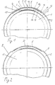
- FIG. 2 shows a second embodiment of the device in which the peripheral outer surface 17 of the tear tab 5 with a marking or marking corrugation 22 is provided and compared to the circumferential Outer surface 9 of the protective element 2 in the direction of the common Normals 21 back to the container wall 3 is such that with machine color printing only the circumferential Outer surface 9 of the protective element 2 can be printed is.
Landscapes
- Engineering & Computer Science (AREA)
- Mechanical Engineering (AREA)
- Closures For Containers (AREA)
- Closing Of Containers (AREA)
- Auxiliary Devices For And Details Of Packaging Control (AREA)
Abstract
Description
Die Erfindung ermöglicht es, Behälter mit perforationsartigem Originalitätsverschluß in ökonomischer und effektiver Weise so zu kennzeichnen, daß die in Umfangsrichtung in das mit der Behälterwand einstückig ausgebildete Schutzelement integrierte Abreißlasche zum einen für einen Benutzer sofort optisch erfaßbar und bequem zu handhaben ist, und daß zum anderen eine unbefugte Erstöffung des Behälters signalartig optisch anzeigbar ist.
- Fig. 1
- eine bruchstückartige Draufsicht auf eine erste Ausführungsform der Vorrichtung, bei der die umfangsmäßige Außenfläche der Abreißlasche - gesehen in der radialen Richtung - von der umfangsmäßigen Außenfläche des einstückig mit der Behälterwand ausgebildeten Schutzelementes vorsteht, und
- Fig. 2
- eine bruchstückartige Draufsicht einer zweiten Ausführungsform der Vorrichtung, bei der die umfangsmäßige Außenfläche der Abreißlasche - gesehen in der radialen Richtung - hinter der umfangsmäßigen Außenfläche des mit der Behälterwand einstückig ausgebildeten Schutzelementes zurücksteht.
Die umfangsmäßige Außenfläche 17 der Abreißlasche 5 ist von einer Vielzahl zinnenartiger Erhebungen 18 gebildet, die in Umfangsrichtung im gleichen Abstand zueinander angeordnet sind. Die zinnenartigen Erhebungen 18, deren Grundriß kegelstumpfförmig ist, ragen jeweils in einer gleichen geringfügigen Höhe über die umfangsmäßige Außenfläche 9 des Schutzelementes 2 in radialer Richtung - gesehen in Fig. 1 - vor derart, daß ihre jeweiligen umfangsmäßigen Außenflächen 17a auf einer Umfangslinie liegen und die umfangsmäßige Außenfläche 17 der Abreißlasche 5 und damit allein die maschinell bedruckbare Kennzeichnungsfläche bilden. Die schlitzartigen Abstände 20 zwischen den zinnenartigen Erhebungen 18 der Abreißlasche 5 kompensieren die Materialverdrängung beim Druckvorgang und gewährleisten eine glattflächige Bedruckung der umfangsmäßigen Außenfläche des perforationsartigen Originalitätsverschlusses.
Die Abreißlasche 5, deren Laschenenden 19 vorzugsweise lose sind, ist für einen Benutzer trotz ihrer im wesentlichen umfangsmäßigen Integration in das Schutzelement 2 infolge ihrer sich farblich abhebenden Kennzeichnung schnell optisch erfaßbar und verhältnismäßig bequem entfernbar, um den Deckelrand dem Öffnungszugriff zugänglich zu machen.
- 1
- Rundbehälter
- 2
- Schutzelement
- 3
- Behälterwand
- 4
- stufenförmige Ausnehmung
- 5
- Abreißlasche
- 6
- untere Kante der Abreißlasche
- 7
- Auskragung
- 8
- Sollbruchstellen
- 9
- Außenfläche des Schutzelementes
- 10
- obere Kante der Abreißlasche
- 11
- untere Kante des Schutzelementes
- 12
- obere Kante des Schutzelementes
- 13
- Teile der Abreißlasche
- 14
- Innenfläche der Abreißlasche
- 15
- Sollbruchstellen
- 16
- stufenförmige Absätze des Schutzelementes
- 17
- umfangsmäßige Außenfläche der Abreißlasche
- 18
- zinnenartige Erhebungen
- 19
- Laschenenden
- 20
- schlitzartige Abstände
- 21
- Normale zur Behälterwand
- 22
- Markierungsriffelung
- 17a
- unfangsmäßige Außenflächen der Erhebungen
Claims (7)
- Vorrichtung zur Sicherung von durch ein Verschlußelement verschlossenen Kunststoffbehältern gegen unbefugte Erstöffnung, deren oberer Rand ein umlaufendes, mit der Behälterwand einstückig ausgebildetes und den umlaufenden Rand des Verschlußelementes abdeckendes Schutzelement umfaßt, durch das die Abnahme des Verschlußelementes behindert ist und das mindestens eine stufenartige Ausnehmung aufweist, die sich teilweise über die Umfangslänge des Verschlußelementes erstreckt und in die eine Abreißlasche eingepaßt ist, deren obere und untere Kante mit der oberen bzw. der unteren Kante des Schutzelementes fluchten,die an ihrer unteren Kante eine über Sollbruchstellen mit der Behälterwand verbundene Auskragung aufweist und die beidseitig der Auskragung im Bereich der stufenförmigen Ausnehmung mit der Lascheninnenfläche über Sollbruchstellen mit dem Schutzelement halterungsßig verbunden ist sowie nach ihrem Entfernen den Deckelrand dem Öffnungsgriff zugänglich macht,
dadurch gekennzeichnet, daß
die umfangsmäßige Außenfläche (9) des mit der Behälterwand (3) einstückig ausgebildeten Schutzelementes (2) und die umfangsmäßige Außenfläche (17) der umfangsmäßig als perforationsmäßiger Originalitätsverschluß in das Schutzelement (2) eingepaßten Abreißlasche (5) in Richtung der gemeinsamen Normalen (21) auf die Behälterwand (3) geringfügig zueinander versetzt sind derart, daß nur die umfangsmäßige Außenfläche (9) des Schutzelementes (2) bzw. die umfangsmäßige Außenfläche (17) der Abreißlasche (5) zur signalartigen, optisch erfaßbaren Kennzeichnung letzterer maschinell farblich bedruckbar ist. - Vorrichtung nach Anspruch 1, dadurch gekennzeichnet,daß die umfangsmäßige Außenfläche (17) der Abreißlasche (5) von einer Vielzahl umfangsmäßig im gleichen Abstand zueinander angeordneter, jeweils in einer gleichen geringfügigen Höhe über die umfangsmäßige Außenfläche (9) des Schutzelementes (2) in Richtung der gemeinsamen Normalen zur Behälterwand (3) vorragender,zinnenartiger Erhebungen (18) der Abreißlasche (5) gebildet ist, deren auf einer Umfangslinie liegenden jeweiligen Außenflächen (17a)allein die maschinell bedruckbare Fläche bilden.
- Vorrichtung nach Anspruch 1, dadurch gekennzeichnet,daß die umfangsmäßige Außenfläche (17) der Abreißlasche (5) mit einer Markierungsriffelung (22) versehen ist und gegenüber der umfangsmäßigen Außenfläche (9) des Schutzlementes (2) in Richtung der gemeinsamen Normalen (21) zur Behälterwand (3) geringfügig zurücksteht derart,daß bei der maschinellen Farbbedruckung allein die umfangsmäßige Außenfläche (9) des Schutzelementes (2) bedruckbar ist.
- Vorrichtung zur Sicherung von durch ein Verschlußelement verschlossenen Kunststoffbehältern gegen unbefugte Erstöffnung, deren oberer Rand ein umlaufendes, mit der Behälterwand einstückig ausgebildetes und den umlaufenden Rand des Verschlußelementes abdeckendes Schutzelement umfaßt, durch das die Abnahme des Verschlußelementes behindert ist und das mindestens eine stufenartige Ausnehmung aufweist, die sich teilweise über die Umfangslänge des Verschlußelementes erstreckt und in die eine Abreißlasche eingepaßt ist, deren obere und untere Kante mit der oberen bzw. der unteren Kante des Schutzelementes fluchten, deren umfangsmäßige Außenfläche schlüssig mit der umfangsmäßigen Außenfläche des Schutzelementes verläuft und die an ihrer unteren Kante eine über Sollbruchstellen mit der Behälterwand verbundene Auskragung aufweist, beidseitig der Auskragung im Bereich der stufenförmigen Ausnehmung mit dem Schutzelement halterungsmäßig verbunden ist sowie nach ihrem Entfernen den Deckelrand dem Öffnungsgriff zugänglich macht,
dadurch gekennzeichnet, daß
die Vorrichtung im Spritzgußverfahren hergestellt ist derart,daß das mit der Behälterwand (3) einstückig ausgebildete Schutzelement (2) gegenüber der den perforationsmäßigen Originalitätsverschluß bildenden Abreißlasche (5) bzw. die Abreißlasche (5) gegenüber dem Schutzelement (2) im 2-Farben-Spritzverfahren, signalartig optisch erfaßbar, farblich hervorgehoben ist. - Verfahren zur signalartigen Kennzeichnung einer Vorrichtung zur Sicherung von durch ein Verschlußelement verschlossenen Kunststoffbehältern gegen unbefugte Erstöffnung, bei dem ein den oberen Rand des Behälters umlaufendes und den umlaufenden Rand des Verschlußelementes abdeckendes Schutzelement einstückig mit der Behälterwand ausgebildet wird, durch das die Abnahme des Verschlußelementes verhindert wird und das mit mindestens einer stufenartigen Ausnehmung versehen wird, die sich teilweise über die Umfangslänge des Verschlußelementes erstreckt und in die eine Abreißlasche eingepaßt wird, deren obere und untere Kante mit der oberen bzw. der unteren Kante des Verschlußelementes fluchten, deren umfangsmäßige Außenfläche schlüssig mit der umfangsmäßigen Außenfläche des Schutzelementes ausgerichtet wird, die an ihrer unteren Kante mit einer Auskragung versehen wird, die über Sollbruchstellen mit der Behälterwand verbunden wird, und die beidseitig der Auskragung im Bereich der stufenförmigen Ausnehmung mit dem Schutzelement halterungsmäßig verbunden wird derart,daß der Deckelrand durch Entfernen der Abreißlasche zugänglich gemacht wird,
dadurch gekennzeichnet, daß
die Vorrichtung im Spritzgußverfahren derart hergestellt wird, daß das mit der Behälterwand einstückig herzustellende Schutzelement gegenüber der in die stufenförmige Ausnehmung des Schutzelementes einzupassenden Abreißlasche oder die Abreißlasche gegenüber dem Schutzelement im 2-Farben-Spritzverfahren optisch gut erfaßbar, farblich signalartig hervorgehoben wird. - Verfahren zur Kennzeichnung der Vorrichtung nach Patentanspruch 1 und 2, dadurch gekennzeichnet, daß der mit dem Originalitätsverschluß versehene Behälter und eine Farbdruckwalze sich relativ zueinander drehend in Kontakt gebracht werden, wobei lediglich die umfangsmäßigen Außenflächen der zinnenartigen Erhebungen der Abreißlasche signalartig farbig bedruckt werden.
- Verfahren zur Kennzeichnung der Vorrichtung nach Patentanspruch 1 und 3, dadurch gekennzeichnet, daß der mit dem Originalitätsverschluß versehene Behälter und eine Farbdruckwalze sich relativ zueinander drehend in Kontakt gebracht werden, wobei nur die umfangsmäßige Außenfläche des mit der Behälterwand einstückig ausgebildeten Schutzelementes signalartig farbig bedruckt wird.
Applications Claiming Priority (2)
| Application Number | Priority Date | Filing Date | Title |
|---|---|---|---|
| DE19737900 | 1997-08-31 | ||
| DE19737900A DE19737900C2 (de) | 1997-08-31 | 1997-08-31 | Vorrichtung zur Sicherung von durch ein Verschlußelement verschlossenen Kunststoffbehältern und Verfahren zur Kennzeichnung der Vorrichtung |
Publications (2)
| Publication Number | Publication Date |
|---|---|
| EP0899205A1 true EP0899205A1 (de) | 1999-03-03 |
| EP0899205B1 EP0899205B1 (de) | 2003-05-21 |
Family
ID=7840684
Family Applications (1)
| Application Number | Title | Priority Date | Filing Date |
|---|---|---|---|
| EP97119475A Expired - Lifetime EP0899205B1 (de) | 1997-08-31 | 1997-11-07 | Vorrichtung zur Sicherung von durch ein Verschlusselement verschlossenen Kunststoffbehältern und Verfahren zur Kennzeichnung der Vorrichtung |
Country Status (4)
| Country | Link |
|---|---|
| EP (1) | EP0899205B1 (de) |
| AT (1) | ATE240877T1 (de) |
| DE (2) | DE19737900C2 (de) |
| DK (1) | DK0899205T3 (de) |
Cited By (1)
| Publication number | Priority date | Publication date | Assignee | Title |
|---|---|---|---|---|
| EP1702739A1 (de) * | 2005-03-18 | 2006-09-20 | Superfos A/S | Verfahren zum Aufbringen von Farbe oder Druck auf einen Kunststoffbehälter und Behälter mit einer farbigen Schürze |
Families Citing this family (1)
| Publication number | Priority date | Publication date | Assignee | Title |
|---|---|---|---|---|
| DE202011100532U1 (de) † | 2011-05-11 | 2012-08-14 | Pöppelmann Holding GmbH & Co. KG | Verpackungsbehältnis |
Citations (4)
| Publication number | Priority date | Publication date | Assignee | Title |
|---|---|---|---|---|
| EP0443750A1 (de) * | 1990-02-07 | 1991-08-28 | Colgate-Palmolive Company | Garantiesiegel |
| DE4418935A1 (de) * | 1994-05-31 | 1995-12-14 | Spritzguswerk Kg Richard Rassb | Vorrichtung zur Sicherung von durch ein Verschlußelement verschlossenen Behältern jeder Art gegen unbefugte Erstöffnung |
| DE19512108A1 (de) * | 1994-05-31 | 1996-10-10 | Spritzguswerk Kg Richard Rassb | Vorrichtung zur Sicherung von durch ein Verschlußelement verschlossenen Behältern jeder Art gegen unbefugte Erstöffnung |
| DE29702676U1 (de) * | 1997-02-16 | 1997-04-30 | Spritzgußwerk KG Richard Rassbach GmbH & Co, 13509 Berlin | Behälter mit einem einen tiefgezogenen Boden aufweisenden Deckel |
Family Cites Families (3)
| Publication number | Priority date | Publication date | Assignee | Title |
|---|---|---|---|---|
| NO144337C (no) * | 1974-08-01 | 1981-08-12 | Dme Plastic 1976 As | Beholder av plast. |
| NL8902303A (nl) * | 1989-09-14 | 1990-07-02 | Brink Gereedschappenfab Bv V D | Houder met deksel uit kunststofmateriaal. |
| DE4138879C1 (de) * | 1991-11-27 | 1992-12-17 | Jokey-Plastik Wipperfuerth Gmbh, 5272 Wipperfuerth, De |
-
1997
- 1997-08-31 DE DE19737900A patent/DE19737900C2/de not_active Expired - Fee Related
- 1997-11-07 EP EP97119475A patent/EP0899205B1/de not_active Expired - Lifetime
- 1997-11-07 AT AT97119475T patent/ATE240877T1/de not_active IP Right Cessation
- 1997-11-07 DK DK97119475T patent/DK0899205T3/da active
- 1997-11-07 DE DE59710131T patent/DE59710131D1/de not_active Expired - Fee Related
Patent Citations (4)
| Publication number | Priority date | Publication date | Assignee | Title |
|---|---|---|---|---|
| EP0443750A1 (de) * | 1990-02-07 | 1991-08-28 | Colgate-Palmolive Company | Garantiesiegel |
| DE4418935A1 (de) * | 1994-05-31 | 1995-12-14 | Spritzguswerk Kg Richard Rassb | Vorrichtung zur Sicherung von durch ein Verschlußelement verschlossenen Behältern jeder Art gegen unbefugte Erstöffnung |
| DE19512108A1 (de) * | 1994-05-31 | 1996-10-10 | Spritzguswerk Kg Richard Rassb | Vorrichtung zur Sicherung von durch ein Verschlußelement verschlossenen Behältern jeder Art gegen unbefugte Erstöffnung |
| DE29702676U1 (de) * | 1997-02-16 | 1997-04-30 | Spritzgußwerk KG Richard Rassbach GmbH & Co, 13509 Berlin | Behälter mit einem einen tiefgezogenen Boden aufweisenden Deckel |
Cited By (1)
| Publication number | Priority date | Publication date | Assignee | Title |
|---|---|---|---|---|
| EP1702739A1 (de) * | 2005-03-18 | 2006-09-20 | Superfos A/S | Verfahren zum Aufbringen von Farbe oder Druck auf einen Kunststoffbehälter und Behälter mit einer farbigen Schürze |
Also Published As
| Publication number | Publication date |
|---|---|
| EP0899205B1 (de) | 2003-05-21 |
| DK0899205T3 (da) | 2003-09-15 |
| DE19737900A1 (de) | 1999-03-04 |
| ATE240877T1 (de) | 2003-06-15 |
| DE59710131D1 (de) | 2003-06-26 |
| DE19737900C2 (de) | 2002-12-05 |
Similar Documents
| Publication | Publication Date | Title |
|---|---|---|
| DE69630596T2 (de) | Originalitätsverschluss mit garantieband | |
| DE2432444C2 (de) | Griffringsbefestigung für einen fälschungssicheren Verschluß | |
| DE3714582A1 (de) | Verpackung mit garantieverschluss | |
| DE3014689C2 (de) | ||
| DE60206374T2 (de) | Originalitätsverschluss | |
| DE69504065T2 (de) | Originalitäts-scharnierverschluss | |
| DE69708763T2 (de) | Schutzverschluss-Sicherungsetikett und Flaschenkappe | |
| DE3111692A1 (de) | Einstueckig geformte verschlusskappen zum abdichten eines behaelters, insbesondere einer flasche | |
| DE2425788A1 (de) | Verschlussdeckel | |
| EP0298352B1 (de) | Originalitätssicherung | |
| DE4418935C2 (de) | Vorrichtung zur Sicherung von durch ein Verschlußelement verschlossenen Behältern jeder Art gegen unbefugte Erstöffnung | |
| DE3416179C2 (de) | ||
| DE60004076T2 (de) | Verschluss, insbesondere für flaschen alkoholische getränke guter qualität enthaltend | |
| DE2813454A1 (de) | Verschluss, insbesondere flaschenverschluss, fuer verkaufsfoerdernde zwecke | |
| CH656104A5 (de) | Kunststoffbehaelter mit deckel. | |
| DE102017117557A1 (de) | Applikationssystem | |
| DE102021000404A1 (de) | Originalitätsverschlusskappe aus Kunststoff | |
| DE69302434T2 (de) | Sicherheitssiegel | |
| EP0899205A1 (de) | Vorrichtung zur Sicherung von durch ein Verschlusselement verschlossenen Kunststoffbehältern und Verfahren zur Kennzeichnung der Vorrichtung | |
| EP0531479B1 (de) | Flaschenverschluss aus kunststoff | |
| DE69725690T2 (de) | Verschlusskappe für einen mit einem Befestigungsflansch versehenen Behälter | |
| DE2743270A1 (de) | Originalverschluss fuer einen behaelter | |
| EP0835825B1 (de) | Gegen Korrosion schützender Verpackungsbehälter | |
| DE69622060T2 (de) | Kindersichere Verschlussanordnung | |
| DE29715566U1 (de) | Vorrichtung zur Sicherung von durch ein Verschlußelement verschlossenen Kunststoffbehältern |
Legal Events
| Date | Code | Title | Description |
|---|---|---|---|
| PUAI | Public reference made under article 153(3) epc to a published international application that has entered the european phase |
Free format text: ORIGINAL CODE: 0009012 |
|
| AK | Designated contracting states |
Kind code of ref document: A1 Designated state(s): AT BE CH DE DK FR GB IT LI NL SE |
|
| AX | Request for extension of the european patent |
Free format text: AL;LT;LV;MK;RO;SI |
|
| 17P | Request for examination filed |
Effective date: 19990819 |
|
| AKX | Designation fees paid |
Free format text: AT BE CH DE DK FR GB IT LI NL SE |
|
| 17Q | First examination report despatched |
Effective date: 20010918 |
|
| GRAG | Despatch of communication of intention to grant |
Free format text: ORIGINAL CODE: EPIDOS AGRA |
|
| GRAG | Despatch of communication of intention to grant |
Free format text: ORIGINAL CODE: EPIDOS AGRA |
|
| GRAH | Despatch of communication of intention to grant a patent |
Free format text: ORIGINAL CODE: EPIDOS IGRA |
|
| GRAG | Despatch of communication of intention to grant |
Free format text: ORIGINAL CODE: EPIDOS AGRA |
|
| GRAH | Despatch of communication of intention to grant a patent |
Free format text: ORIGINAL CODE: EPIDOS IGRA |
|
| GRAH | Despatch of communication of intention to grant a patent |
Free format text: ORIGINAL CODE: EPIDOS IGRA |
|
| GRAA | (expected) grant |
Free format text: ORIGINAL CODE: 0009210 |
|
| AK | Designated contracting states |
Designated state(s): AT BE CH DE DK FR GB IT LI NL SE |
|
| PG25 | Lapsed in a contracting state [announced via postgrant information from national office to epo] |
Ref country code: IT Free format text: LAPSE BECAUSE OF FAILURE TO SUBMIT A TRANSLATION OF THE DESCRIPTION OR TO PAY THE FEE WITHIN THE PRE;WARNING: LAPSES OF ITALIAN PATENTS WITH EFFECTIVE DATE BEFORE 2007 MAY HAVE OCCURRED AT ANY TIME BEFORE 2007. THE CORRECT EFFECTIVE DATE MAY BE DIFFERENT FROM THE ONE RECORDED.SCRIBED TIME-LIMIT Effective date: 20030521 |
|
| REG | Reference to a national code |
Ref country code: GB Ref legal event code: FG4D Free format text: NOT ENGLISH |
|
| REG | Reference to a national code |
Ref country code: CH Ref legal event code: EP |
|
| REF | Corresponds to: |
Ref document number: 59710131 Country of ref document: DE Date of ref document: 20030626 Kind code of ref document: P |
|
| PG25 | Lapsed in a contracting state [announced via postgrant information from national office to epo] |
Ref country code: SE Free format text: LAPSE BECAUSE OF FAILURE TO SUBMIT A TRANSLATION OF THE DESCRIPTION OR TO PAY THE FEE WITHIN THE PRESCRIBED TIME-LIMIT Effective date: 20030821 |
|
| REG | Reference to a national code |
Ref country code: DK Ref legal event code: T3 |
|
| GBT | Gb: translation of ep patent filed (gb section 77(6)(a)/1977) |
Effective date: 20031015 |
|
| PG25 | Lapsed in a contracting state [announced via postgrant information from national office to epo] |
Ref country code: AT Free format text: LAPSE BECAUSE OF NON-PAYMENT OF DUE FEES Effective date: 20031107 |
|
| PG25 | Lapsed in a contracting state [announced via postgrant information from national office to epo] |
Ref country code: LI Free format text: LAPSE BECAUSE OF NON-PAYMENT OF DUE FEES Effective date: 20031130 Ref country code: CH Free format text: LAPSE BECAUSE OF NON-PAYMENT OF DUE FEES Effective date: 20031130 |
|
| ET | Fr: translation filed | ||
| PLBE | No opposition filed within time limit |
Free format text: ORIGINAL CODE: 0009261 |
|
| STAA | Information on the status of an ep patent application or granted ep patent |
Free format text: STATUS: NO OPPOSITION FILED WITHIN TIME LIMIT |
|
| 26N | No opposition filed |
Effective date: 20040224 |
|
| PG25 | Lapsed in a contracting state [announced via postgrant information from national office to epo] |
Ref country code: DE Free format text: LAPSE BECAUSE OF NON-PAYMENT OF DUE FEES Effective date: 20040602 |
|
| REG | Reference to a national code |
Ref country code: CH Ref legal event code: PL |
|
| PGFP | Annual fee paid to national office [announced via postgrant information from national office to epo] |
Ref country code: BE Payment date: 20091123 Year of fee payment: 13 |
|
| PGFP | Annual fee paid to national office [announced via postgrant information from national office to epo] |
Ref country code: NL Payment date: 20101108 Year of fee payment: 14 Ref country code: FR Payment date: 20101130 Year of fee payment: 14 Ref country code: DK Payment date: 20101124 Year of fee payment: 14 |
|
| PGFP | Annual fee paid to national office [announced via postgrant information from national office to epo] |
Ref country code: GB Payment date: 20101123 Year of fee payment: 14 |
|
| BERE | Be: lapsed |
Owner name: SPRITZGUSSWERK K.G. RICHARD *RASSBACH G.M.B.H. & C Effective date: 20101130 |
|
| PG25 | Lapsed in a contracting state [announced via postgrant information from national office to epo] |
Ref country code: BE Free format text: LAPSE BECAUSE OF NON-PAYMENT OF DUE FEES Effective date: 20101130 |
|
| REG | Reference to a national code |
Ref country code: NL Ref legal event code: V1 Effective date: 20120601 |
|
| REG | Reference to a national code |
Ref country code: DK Ref legal event code: EBP |
|
| GBPC | Gb: european patent ceased through non-payment of renewal fee |
Effective date: 20111107 |
|
| PG25 | Lapsed in a contracting state [announced via postgrant information from national office to epo] |
Ref country code: NL Free format text: LAPSE BECAUSE OF NON-PAYMENT OF DUE FEES Effective date: 20120601 |
|
| REG | Reference to a national code |
Ref country code: FR Ref legal event code: ST Effective date: 20120731 |
|
| PG25 | Lapsed in a contracting state [announced via postgrant information from national office to epo] |
Ref country code: DK Free format text: LAPSE BECAUSE OF NON-PAYMENT OF DUE FEES Effective date: 20111130 Ref country code: GB Free format text: LAPSE BECAUSE OF NON-PAYMENT OF DUE FEES Effective date: 20111107 |
|
| PG25 | Lapsed in a contracting state [announced via postgrant information from national office to epo] |
Ref country code: FR Free format text: LAPSE BECAUSE OF NON-PAYMENT OF DUE FEES Effective date: 20111130 |