EP0894586B1 - Verfahren und vorrichtung zum trockenpressen von geschirrgegenständen , insbesondere tellern - Google Patents
Verfahren und vorrichtung zum trockenpressen von geschirrgegenständen , insbesondere tellern Download PDFInfo
- Publication number
- EP0894586B1 EP0894586B1 EP98202460A EP98202460A EP0894586B1 EP 0894586 B1 EP0894586 B1 EP 0894586B1 EP 98202460 A EP98202460 A EP 98202460A EP 98202460 A EP98202460 A EP 98202460A EP 0894586 B1 EP0894586 B1 EP 0894586B1
- Authority
- EP
- European Patent Office
- Prior art keywords
- base
- membrane
- punch
- crockery
- plant
- Prior art date
- Legal status (The legal status is an assumption and is not a legal conclusion. Google has not performed a legal analysis and makes no representation as to the accuracy of the status listed.)
- Expired - Lifetime
Links
- 238000000034 method Methods 0.000 title claims description 13
- 239000012528 membrane Substances 0.000 claims description 26
- 239000007788 liquid Substances 0.000 claims description 18
- 239000000843 powder Substances 0.000 claims description 17
- 238000005056 compaction Methods 0.000 claims description 9
- 239000000463 material Substances 0.000 claims description 7
- 230000010349 pulsation Effects 0.000 claims description 6
- 239000000919 ceramic Substances 0.000 claims description 3
- 230000006835 compression Effects 0.000 claims description 3
- 238000007906 compression Methods 0.000 claims description 3
- 230000000630 rising effect Effects 0.000 claims description 2
- 238000002604 ultrasonography Methods 0.000 claims description 2
- 230000000694 effects Effects 0.000 description 3
- 229920001971 elastomer Polymers 0.000 description 3
- 238000000280 densification Methods 0.000 description 2
- 230000000994 depressogenic effect Effects 0.000 description 2
- 229910000831 Steel Inorganic materials 0.000 description 1
- 238000010586 diagram Methods 0.000 description 1
- 239000000806 elastomer Substances 0.000 description 1
- 238000005516 engineering process Methods 0.000 description 1
- 238000010304 firing Methods 0.000 description 1
- 238000004519 manufacturing process Methods 0.000 description 1
- 238000012986 modification Methods 0.000 description 1
- 230000004048 modification Effects 0.000 description 1
- 229910052573 porcelain Inorganic materials 0.000 description 1
- 238000003825 pressing Methods 0.000 description 1
- 239000010959 steel Substances 0.000 description 1
Images

Classifications
-
- B—PERFORMING OPERATIONS; TRANSPORTING
- B30—PRESSES
- B30B—PRESSES IN GENERAL
- B30B15/00—Details of, or accessories for, presses; Auxiliary measures in connection with pressing
- B30B15/02—Dies; Inserts therefor; Mounting thereof; Moulds
- B30B15/022—Moulds for compacting material in powder, granular of pasta form
- B30B15/024—Moulds for compacting material in powder, granular of pasta form using elastic mould parts
-
- B—PERFORMING OPERATIONS; TRANSPORTING
- B28—WORKING CEMENT, CLAY, OR STONE
- B28B—SHAPING CLAY OR OTHER CERAMIC COMPOSITIONS; SHAPING SLAG; SHAPING MIXTURES CONTAINING CEMENTITIOUS MATERIAL, e.g. PLASTER
- B28B3/00—Producing shaped articles from the material by using presses; Presses specially adapted therefor
- B28B3/003—Pressing by means acting upon the material via flexible mould wall parts, e.g. by means of inflatable cores, isostatic presses
-
- B—PERFORMING OPERATIONS; TRANSPORTING
- B28—WORKING CEMENT, CLAY, OR STONE
- B28B—SHAPING CLAY OR OTHER CERAMIC COMPOSITIONS; SHAPING SLAG; SHAPING MIXTURES CONTAINING CEMENTITIOUS MATERIAL, e.g. PLASTER
- B28B3/00—Producing shaped articles from the material by using presses; Presses specially adapted therefor
- B28B3/02—Producing shaped articles from the material by using presses; Presses specially adapted therefor wherein a ram exerts pressure on the material in a moulding space; Ram heads of special form
- B28B3/022—Producing shaped articles from the material by using presses; Presses specially adapted therefor wherein a ram exerts pressure on the material in a moulding space; Ram heads of special form combined with vibrating or jolting
Definitions
- This invention relates to the manufacture of plates and crockery of fine ceramic, such as porcelain, and in particular to so-called isostatic methods and plants.
- the isostatic method for dry-compacting powders uses so-called isostatic moulds in which a base has the shape of one side of the plate, against which there rests an elastomeric membrane of substantially constant thickness, sealedly fixed perimetrally.
- the base of the mould is positioned in front of a movable punch of the same shape as the other side of the plate.
- the various stages in forming the crude plate, ie ready for firing in a suitable kiln comprise arranging a layer of soft ceramic powder on the base, moving the punch towards the base until it closes the compartment formed between the base and punch without exerting substantial pressure on the powder, and feeding a pressurized liquid onto the rear of the elastomeric membrane which covers the base, with consequent raising of the membrane from the base on which it rests, and compression of the material to achieve the compaction required to form the plate.
- the document DD139109 discloses a method and apparatus for dry forming crockery by means of isostatic moulds having a punch shaped as one of the two sides of the crockery, a base shaped as the other side of the crockery, and a membrane having the same shape as the punch, which rests thereon and is sealedly fixed perimetrally thereto, and means for moving the punch towards the base and means for feeding a hydraulic liquid onto the rear of the membrane when the punch is positioned against the base to define a forming chamber, with consequent rising of the membrane from the punch on which it rests, and compression of the material to achieve the compaction required to form the crockery, wherein the base is subjected to vibrations.
- the document JP 63030199 discloses a isotropic pressure pressing method in which the compaction pressure is given by a pressure generator, and is maintained while pulsation is generated by actuating a cylinder via an electric motor.
- JP 63030199 achieves an improved material compaction, wherein the pulsation generation means are different and separated from the pressure generation means.
- the object of this invention is to achieve material compaction suitable for modern technological requirements while maintaining the pressure of the membrane operating liquid relatively low, and hence maintaining low stressing forces on the press structure and a low required capacity of the pressurized hydraulic liquid generator.
- the number of pressure pulses to be imposed on the membrane is conveniently less than 50 per cycle, it having been found that after a certain number of pulses a saturation effect occurs so that compaction is not further substantially increased.
- the number of pressure pulses can also be uncontrolled, if the pulses are generated by a vibrator or by an ultrasound generator in contact with the hydraulic liquid.
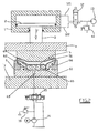
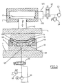
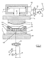
- the figures show the main hydraulic press cylinder 1 within which there slides a piston 2, to the rod 3 of which the movable cross-member 4 is fixed.
- the hydraulic cylinder 1 is connected above and below the piston 2 to a pressurized hydraulic liquid source and to discharge respectively, and vice versa, by the distributor valve 12 and the pipes 121 and 122.
- the movable cross-member 4 lowerly carries a steel punch 5 covered with a rubber membrane 51.
- the mould 6 comprises a lower part 61 having a depressed central region 62 from which there extends a conduit 63 opening externally for the hydraulic operating liquid for the mould.
- An outer frame 66 sealedly locks a membrane 67 of an elastomer such as rubber, which rests on the upper surface of the mould upper part 64.
- the conduit 63 is connected to a source 16 of pressurized hydraulic liquid.
- a maximum pressure valve 18 of adjustable setting Downstream of the source 16 there are a maximum pressure valve 18 of adjustable setting, and a servovalve 15 which can operate either as a distributor valve or as a hydraulic pulsation generator, in this latter case by oscillating between the feed position and the discharge position.
- the aforedescribed plant operates as follows.
- the powder is compressed in the stage shown in Figure 3, in which the distributor valve 12 is fed as in Figure 2, the distributor valve 8 allowing pressurized hydraulic liquid to occupy the space below the membrane, to exert a base pressure on the membrane and through this onto the powder.
- the pulse generator 10 On attaining the base pressure the pulse generator 10 operates to cyclically discharge the liquid feed pipe and reclose it immediately afterwards, with repeated action, to subject the membrane 67 and with it the powder contained in the mould to a cycle of close-together pulses, similar to vibrations.
- the programmed and magnetically controlled slider of the distributor valve 12 can operate.
- the pressure of the liquid fed by the source is between 100 and 400 bar, the pulse frequency being between 1 and 50 Hz.
- the hydraulic pulse generator can take the form of other devices, such as a rotary distributor valve suitably operated by an hydraulic actuator or an electric or hydraulic motor of adjustable speed and position, which connects the feed conduit 63 for the chamber behind the membrane to a hydraulic pressure source and to discharge alternately.
- a rotary distributor valve suitably operated by an hydraulic actuator or an electric or hydraulic motor of adjustable speed and position, which connects the feed conduit 63 for the chamber behind the membrane to a hydraulic pressure source and to discharge alternately.
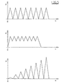
- the pulsation cycle can vary in terms of frequency, number and intensity of pulses and the form of the pressure wave, which can assume one of the forms shown in Figure 5.
Landscapes
- Engineering & Computer Science (AREA)
- Mechanical Engineering (AREA)
- Manufacturing & Machinery (AREA)
- Chemical & Material Sciences (AREA)
- Ceramic Engineering (AREA)
- Press Drives And Press Lines (AREA)
- Press-Shaping Or Shaping Using Conveyers (AREA)
- Powder Metallurgy (AREA)
- Saccharide Compounds (AREA)
Claims (7)
- Verfahren zum Trockenformen von Steingut mittels einer isostatischen Pressform, welche einen Stempel (5), der als eine der zwei Seiten des Steinguts geformt ist, eine Basis (64), welche als die andere Seite des Steinguts geformt ist, und eine Membran aufweist, welche die gleiche Form wie die Basis (64) aufweist und welche auf der Basis (64) ruht und dichtend umlaufend an derselben befestigt ist, sowie eine Einrichtung zum Bewegen des Stempels (5) in Richtung der Basis und Einrichtungen (13,63,65) zum Zuführen einer Hydraulikflüssigkeit auf die Hinterseite bzw. Rückseite der Membran (67), wenn der Stempel (5) gegen die Basis (64) positioniert ist, um eine dabei vorgesehene Formkammer zu bilden,
gekennzeichnet durch
das Anordnen einer Schicht von weichem Keramikpulver auf der Basis (64), das Bewegen des Stempels (5) in Richtung der Basis (64) bis er die zwischen der Basis (64) und dem Stempel (5) gebildete Kammer ohne das Aufbringen eines wesentlichen Drucks auf das Pulver schließt, und das Zuführen einer unter Druck stehenden Flüssigkeit auf die Rückseite der elastomeren Membran (67), welche die Basis (64) abdeckt, wodurch sich die Membran (67) von der Basis, auf welcher sie ruht, erhebt, und das Zusammendrücken des Materials, um die zur Bildung des Steinguts erforderliche verdichtung zu erreichen, wobei das Pulver während des Aufbringens des Verdichtungsdrucks dicht aufeinanderfolgenden Druckpulsen über ein Verteilerventil (12) ausgesetzt wird, welches dafür vorgesehen ist, die Rückseite der Membran abwechselnd mit dem Zulauf und dem Ablauf zu verbinden. - Verfahren nach Anspruch 1,
dadurch gekennzeichnet, dass
die Druckpulse von endlicher Anzahl sind. - Anlage zum Trockenformen von Steingut mit einer isostatischen Pressform, welche einen Stempel (5), der als eine der zwei Seiten des Steinguts geformt ist, eine Basis (64), welche als die andere Seite des Steinguts geformt ist, wobei eine Formkammer vollständig durch den gegen die Basis positionierten Stempel festgelegt ist, und eine Membran (67) aufweist, welche die gleiche Form wie die Basis (64) aufweist, und welche auf der Basis (64) ruht und dichtend umlaufend an derselben befestigt ist, wobei eine Einrichtung zum Bewegen des Stempels (5) in Richtung der Basis (64) und Einrichtungen (13,63,65) zum Zuführen einer Hydraulikflüssigkeit auf die Rückseite der Membran (67) vorgesehen sind, wenn der Stempel an der Basis (64) positioniert ist, um die Formkammer zu bilden,
dadurch gekennzeichnet , dass
die Zuführeinrichtung (13,63,65) für unter Druck stehende Hydraulikflüssigkeit einen Zulauf für Hydraulikflüssigkeit aufweist, welcher mit der Rückseite der Membran (67) über ein Verteilerventil (12) verbunden ist, welches dafür vorgesehen ist, die Rückseite abwechselnd mit dem Zulauf und einem Ablauf zu verbinden und zwischen diesen Positionen oszilliert, um auf die Rückseite der Membran (67) in der Art und Weise einer Pulsation aufgebrachte Druckpulse zu erzeugen. - Anlage nach Anspruch 3,
dadurch gekennzeichnet, dass
das Verteilerventil (14) ein Schiebe-Servoventil ist, welches durch eine geeignete, programmierte Einrichtung gesteuert ist. - Anlage nach Anspruch 3,
dadurch gekennzeichnet, dass
das Verteilerventil (12) ein Rotationsverteilerventil ist, welches mit einstellbarer Geschwindigkeit und Position betrieben wird. - Anlage nach Anspruch 3,
gekennzeichnet durch
das Aufweisen einer Vibrationsquelle, welche in Kontakt mit der Hydraulikflüssigkeit positioniert ist, um auf die Rückseite der Membran in der Art und Weise einer Pulsation aufgebrachte Druckpulse zu erzeugen. - Anlage nach Anspruch 3,
gekennzeichnet durch
das Aufweisen einer Ultraschallquelle, welche in Kontakt mit der Hydraulikflüssigkeit positioniert ist.
Applications Claiming Priority (2)
| Application Number | Priority Date | Filing Date | Title |
|---|---|---|---|
| IT97RE000060A IT1294945B1 (it) | 1997-08-01 | 1997-08-01 | Procedimento ed impianto per la formatura a secco di stoviglie in genere, particolarmente per piatti |
| ITRE970060 | 1997-08-01 |
Publications (2)
| Publication Number | Publication Date |
|---|---|
| EP0894586A1 EP0894586A1 (de) | 1999-02-03 |
| EP0894586B1 true EP0894586B1 (de) | 2003-08-27 |
Family
ID=11399096
Family Applications (1)
| Application Number | Title | Priority Date | Filing Date |
|---|---|---|---|
| EP98202460A Expired - Lifetime EP0894586B1 (de) | 1997-08-01 | 1998-07-22 | Verfahren und vorrichtung zum trockenpressen von geschirrgegenständen , insbesondere tellern |
Country Status (6)
| Country | Link |
|---|---|
| US (1) | US6372166B1 (de) |
| EP (1) | EP0894586B1 (de) |
| BR (1) | BR9802823A (de) |
| DE (1) | DE69817479T2 (de) |
| ES (1) | ES2205378T3 (de) |
| IT (1) | IT1294945B1 (de) |
Families Citing this family (12)
| Publication number | Priority date | Publication date | Assignee | Title |
|---|---|---|---|---|
| IT1294942B1 (it) * | 1997-08-01 | 1999-04-23 | Sacmi | Procedimento di pressatura di polveri ceramiche ed attrezzatura di attuazione dello stesso. |
| US20120104641A1 (en) | 2010-11-02 | 2012-05-03 | Honeywell International Inc. | Apparatus for pitch densification |
| US20120104659A1 (en) * | 2010-11-02 | 2012-05-03 | Honeywell International Inc. | Apparatus for pitch densification |
| US20120153528A1 (en) | 2010-12-17 | 2012-06-21 | Honeywell International Inc. | Apparatus for carbon fiber processing and pitch densification |
| CN102225629B (zh) * | 2011-04-02 | 2013-10-02 | 太原理工大学 | 多源动压等静压粉体成型工艺 |
| NL2013003B1 (nl) * | 2014-06-16 | 2016-07-04 | Bouman Ind Supplier Group B V | Compactor, werkwijze voor het compacteren van een mengsel en toepassing van een compactor. |
| US10302163B2 (en) | 2015-05-13 | 2019-05-28 | Honeywell International Inc. | Carbon-carbon composite component with antioxidant coating |
| US10131113B2 (en) | 2015-05-13 | 2018-11-20 | Honeywell International Inc. | Multilayered carbon-carbon composite |
| US9944526B2 (en) | 2015-05-13 | 2018-04-17 | Honeywell International Inc. | Carbon fiber preforms |
| US10035305B2 (en) | 2015-06-30 | 2018-07-31 | Honeywell International Inc. | Method of making carbon fiber preforms |
| US10022890B2 (en) | 2015-09-15 | 2018-07-17 | Honeywell International Inc. | In situ carbonization of a resin to form a carbon-carbon composite |
| US10300631B2 (en) | 2015-11-30 | 2019-05-28 | Honeywell International Inc. | Carbon fiber preforms |
Family Cites Families (12)
| Publication number | Priority date | Publication date | Assignee | Title |
|---|---|---|---|---|
| DE139109C (de) | ||||
| DE862415C (de) * | 1949-07-24 | 1953-01-12 | Dynamit Nobel Ag | Vorrichtung zur kontinuierlichen Herstellung und Behandlung von vorzugsweise flaechigen Werkstoffen |
| DE862416C (de) * | 1949-07-24 | 1953-01-12 | Dynamit Nobel Ag | Vorrichtung zur kontinuierlichen Herstellung und Behandlung von vorzugsweise flaechigen Werkstoffen |
| US2618833A (en) * | 1949-09-09 | 1952-11-25 | Denison Eng Co | Apparatus for forming ceramic articles |
| GB821282A (en) * | 1956-03-26 | 1959-10-07 | Production Tool Alloy Company | Improvements in or relating to the production of shaped articles from powders |
| DD139109B1 (de) * | 1978-10-02 | 1981-06-24 | Widra Wolf Dietrich | Vorrichtung zum isostatischen pressen von keramischem flachgeschirr |
| JPH084958B2 (ja) * | 1986-07-23 | 1996-01-24 | 石川島播磨重工業株式会社 | 等方圧圧縮成形プレス |
| JPS63199099A (ja) * | 1987-02-13 | 1988-08-17 | Toyota Motor Corp | 静水圧加圧成形方法 |
| DE4012700A1 (de) * | 1990-04-20 | 1991-10-31 | Hutschenreuther | Verfahren zur herstellung eines keramischen formkoerpers und einrichtung zum pressen eines keramischen formlings |
| DE4320203A1 (de) * | 1993-06-18 | 1994-12-22 | B & B Maschinenbau Gmbh | Wandung für eine Preßform und eine eine derartige Wandung einbeziehende Preßeinrichtung und Preßform |
| IT1280102B1 (it) * | 1995-10-18 | 1997-12-29 | Sacmi | Pressa per la formatura di oggetti con materiale ceramico in polvere |
| DE19602536A1 (de) * | 1996-01-25 | 1997-07-31 | Graefer Albrecht | Verfahren zur Herstellung von Teilen aus Granulaten |
-
1997
- 1997-08-01 IT IT97RE000060A patent/IT1294945B1/it active IP Right Grant
-
1998
- 1998-07-22 EP EP98202460A patent/EP0894586B1/de not_active Expired - Lifetime
- 1998-07-22 DE DE69817479T patent/DE69817479T2/de not_active Expired - Fee Related
- 1998-07-22 ES ES98202460T patent/ES2205378T3/es not_active Expired - Lifetime
- 1998-07-29 US US09/124,039 patent/US6372166B1/en not_active Expired - Fee Related
- 1998-07-31 BR BR9802823-5A patent/BR9802823A/pt not_active IP Right Cessation
Also Published As
| Publication number | Publication date |
|---|---|
| IT1294945B1 (it) | 1999-04-23 |
| ITRE970060A0 (it) | 1997-08-01 |
| BR9802823A (pt) | 1999-11-09 |
| ES2205378T3 (es) | 2004-05-01 |
| DE69817479D1 (de) | 2003-10-02 |
| US6372166B1 (en) | 2002-04-16 |
| ITRE970060A1 (it) | 1999-02-01 |
| DE69817479T2 (de) | 2004-03-11 |
| EP0894586A1 (de) | 1999-02-03 |
Similar Documents
| Publication | Publication Date | Title |
|---|---|---|
| EP0894587B1 (de) | Verfahren zum pressen von keramischen pulvern und vorrichtung zum durchführen des verfahrens | |
| EP0894586B1 (de) | Verfahren und vorrichtung zum trockenpressen von geschirrgegenständen , insbesondere tellern | |
| EP0894588B1 (de) | Verfahren zum Herstellen von keramischen Fliesen, einschliesslich Fliesen mit grossen Abmessungen, durch ein teilweise isostatisches Pressen und Vorrichtung zum durchführen des Verfahrens | |
| EP0681877B2 (de) | Verfahren zum Herstellen von Gussformen | |
| US4412852A (en) | Apparatus for producing brick-shaped blocks of dry ice | |
| US3613166A (en) | Compaction of particulate matter | |
| US6054079A (en) | Method and installation for compacting a granular mass, such as concrete mortar | |
| US6845710B2 (en) | Process and apparatus for compressing metallic powder into a compact | |
| JPH04272804A (ja) | 粒状の石材またはセラミック材料からなるプレートまたはブロックの形の混合物を振動圧密するプレス | |
| US4439129A (en) | Hydraulic refractory press including floating upper and lower plunger assemblies | |
| EP1106336B1 (de) | Vorrichtung zum Entfernen von Luft aus feinpulverförmigem Material während eines Pressenzyklus für die Herstellung von keramischen Gegenständen | |
| EP1136212B1 (de) | Verbesserte Vorrichtung zum Herstellen von keramischen Gegenständen wie zum Beispiel Platten , Fliesen und ähnlichen Artikeln durch Pressen von Pulver | |
| RU2147520C1 (ru) | Устройство для прессования порошкообразных материалов | |
| GB1246435A (en) | A method and apparatus for producing elements of concrete and similar settable materials | |
| SU795970A1 (ru) | Устройство дл вибрационногопРЕССОВАНи | |
| RU2198786C2 (ru) | Устройство полусухого прессования керамических изделий | |
| HU214559B (hu) | Eljárás préselendő anyag szűrőprésbe töltésére | |
| JPS5837361B2 (ja) | 真空粉末成形法 | |
| JPH04157102A (ja) | 粉末成形用金型 | |
| RU2004431C1 (ru) | Способ прессовани изделий из смесей и устройство дл его осуществлени | |
| JPH04323016A (ja) | 圧力制御成形法とその装置 | |
| US6705382B1 (en) | Method of improving the mould quality of mould-forming machine | |
| SU1066725A1 (ru) | Устройство дл изготовлени полуформ с высокими болванами | |
| SU1180158A1 (ru) | Пресс-форма дл изостатического прессовани порошка | |
| JPS58192699A (ja) | プレス成形加工方法及びその装置 |
Legal Events
| Date | Code | Title | Description |
|---|---|---|---|
| PUAI | Public reference made under article 153(3) epc to a published international application that has entered the european phase |
Free format text: ORIGINAL CODE: 0009012 |
|
| AK | Designated contracting states |
Kind code of ref document: A1 Designated state(s): DE ES FR GB IT |
|
| AX | Request for extension of the european patent |
Free format text: AL;LT;LV;MK;RO;SI |
|
| 17P | Request for examination filed |
Effective date: 19990531 |
|
| AKX | Designation fees paid |
Free format text: DE ES FR GB IT |
|
| 17Q | First examination report despatched |
Effective date: 20020510 |
|
| GRAH | Despatch of communication of intention to grant a patent |
Free format text: ORIGINAL CODE: EPIDOS IGRA |
|
| GRAH | Despatch of communication of intention to grant a patent |
Free format text: ORIGINAL CODE: EPIDOS IGRA |
|
| GRAA | (expected) grant |
Free format text: ORIGINAL CODE: 0009210 |
|
| AK | Designated contracting states |
Designated state(s): DE ES FR GB IT |
|
| REG | Reference to a national code |
Ref country code: GB Ref legal event code: FG4D |
|
| REF | Corresponds to: |
Ref document number: 69817479 Country of ref document: DE Date of ref document: 20031002 Kind code of ref document: P |
|
| REG | Reference to a national code |
Ref country code: ES Ref legal event code: FG2A Ref document number: 2205378 Country of ref document: ES Kind code of ref document: T3 |
|
| ET | Fr: translation filed | ||
| PLBE | No opposition filed within time limit |
Free format text: ORIGINAL CODE: 0009261 |
|
| STAA | Information on the status of an ep patent application or granted ep patent |
Free format text: STATUS: NO OPPOSITION FILED WITHIN TIME LIMIT |
|
| 26N | No opposition filed |
Effective date: 20040528 |
|
| PGFP | Annual fee paid to national office [announced via postgrant information from national office to epo] |
Ref country code: ES Payment date: 20080718 Year of fee payment: 11 Ref country code: DE Payment date: 20080730 Year of fee payment: 11 |
|
| PGFP | Annual fee paid to national office [announced via postgrant information from national office to epo] |
Ref country code: IT Payment date: 20080719 Year of fee payment: 11 Ref country code: FR Payment date: 20080730 Year of fee payment: 11 |
|
| PGFP | Annual fee paid to national office [announced via postgrant information from national office to epo] |
Ref country code: GB Payment date: 20080630 Year of fee payment: 11 |
|
| GBPC | Gb: european patent ceased through non-payment of renewal fee |
Effective date: 20090722 |
|
| REG | Reference to a national code |
Ref country code: FR Ref legal event code: ST Effective date: 20100331 |
|
| PG25 | Lapsed in a contracting state [announced via postgrant information from national office to epo] |
Ref country code: FR Free format text: LAPSE BECAUSE OF NON-PAYMENT OF DUE FEES Effective date: 20090731 |
|
| PG25 | Lapsed in a contracting state [announced via postgrant information from national office to epo] |
Ref country code: GB Free format text: LAPSE BECAUSE OF NON-PAYMENT OF DUE FEES Effective date: 20090722 |
|
| PG25 | Lapsed in a contracting state [announced via postgrant information from national office to epo] |
Ref country code: DE Free format text: LAPSE BECAUSE OF NON-PAYMENT OF DUE FEES Effective date: 20100202 |
|
| REG | Reference to a national code |
Ref country code: ES Ref legal event code: FD2A Effective date: 20090723 |
|
| PG25 | Lapsed in a contracting state [announced via postgrant information from national office to epo] |
Ref country code: ES Free format text: LAPSE BECAUSE OF NON-PAYMENT OF DUE FEES Effective date: 20090723 |
|
| PG25 | Lapsed in a contracting state [announced via postgrant information from national office to epo] |
Ref country code: IT Free format text: LAPSE BECAUSE OF NON-PAYMENT OF DUE FEES Effective date: 20090722 |