EP0893849B1 - Elektrischer Steckverbinder - Google Patents
Elektrischer Steckverbinder Download PDFInfo
- Publication number
- EP0893849B1 EP0893849B1 EP98103889A EP98103889A EP0893849B1 EP 0893849 B1 EP0893849 B1 EP 0893849B1 EP 98103889 A EP98103889 A EP 98103889A EP 98103889 A EP98103889 A EP 98103889A EP 0893849 B1 EP0893849 B1 EP 0893849B1
- Authority
- EP
- European Patent Office
- Prior art keywords
- connection
- terminals
- plug connector
- terminal
- connector according
- Prior art date
- Legal status (The legal status is an assumption and is not a legal conclusion. Google has not performed a legal analysis and makes no representation as to the accuracy of the status listed.)
- Expired - Lifetime
Links
Images


Classifications
-
- H—ELECTRICITY
- H01—ELECTRIC ELEMENTS
- H01R—ELECTRICALLY-CONDUCTIVE CONNECTIONS; STRUCTURAL ASSOCIATIONS OF A PLURALITY OF MUTUALLY-INSULATED ELECTRICAL CONNECTING ELEMENTS; COUPLING DEVICES; CURRENT COLLECTORS
- H01R9/00—Structural associations of a plurality of mutually-insulated electrical connecting elements, e.g. terminal strips or terminal blocks; Terminals or binding posts mounted upon a base or in a case; Bases therefor
- H01R9/22—Bases, e.g. strip, block, panel
- H01R9/24—Terminal blocks
- H01R9/2491—Terminal blocks structurally associated with plugs or sockets
-
- H—ELECTRICITY
- H01—ELECTRIC ELEMENTS
- H01R—ELECTRICALLY-CONDUCTIVE CONNECTIONS; STRUCTURAL ASSOCIATIONS OF A PLURALITY OF MUTUALLY-INSULATED ELECTRICAL CONNECTING ELEMENTS; COUPLING DEVICES; CURRENT COLLECTORS
- H01R13/00—Details of coupling devices of the kinds covered by groups H01R12/70 or H01R24/00 - H01R33/00
- H01R13/02—Contact members
- H01R13/10—Sockets for co-operation with pins or blades
- H01R13/11—Resilient sockets
- H01R13/112—Resilient sockets forked sockets having two legs
-
- H—ELECTRICITY
- H01—ELECTRIC ELEMENTS
- H01R—ELECTRICALLY-CONDUCTIVE CONNECTIONS; STRUCTURAL ASSOCIATIONS OF A PLURALITY OF MUTUALLY-INSULATED ELECTRICAL CONNECTING ELEMENTS; COUPLING DEVICES; CURRENT COLLECTORS
- H01R2107/00—Four or more poles
-
- H—ELECTRICITY
- H01—ELECTRIC ELEMENTS
- H01R—ELECTRICALLY-CONDUCTIVE CONNECTIONS; STRUCTURAL ASSOCIATIONS OF A PLURALITY OF MUTUALLY-INSULATED ELECTRICAL CONNECTING ELEMENTS; COUPLING DEVICES; CURRENT COLLECTORS
- H01R31/00—Coupling parts supported only by co-operation with counterpart
- H01R31/02—Intermediate parts for distributing energy to two or more circuits in parallel, e.g. splitter
-
- H—ELECTRICITY
- H01—ELECTRIC ELEMENTS
- H01R—ELECTRICALLY-CONDUCTIVE CONNECTIONS; STRUCTURAL ASSOCIATIONS OF A PLURALITY OF MUTUALLY-INSULATED ELECTRICAL CONNECTING ELEMENTS; COUPLING DEVICES; CURRENT COLLECTORS
- H01R4/00—Electrically-conductive connections between two or more conductive members in direct contact, i.e. touching one another; Means for effecting or maintaining such contact; Electrically-conductive connections having two or more spaced connecting locations for conductors and using contact members penetrating insulation
- H01R4/28—Clamped connections, spring connections
- H01R4/30—Clamped connections, spring connections utilising a screw or nut clamping member
- H01R4/34—Conductive members located under head of screw
Definitions
- the invention relates to an electrical connector with an insulating material and having contacts integral with connectors for forming terminals are led to terminal screws, the connections in two rows are arranged in insulating material.
- a connector for example known from DE 195 00 068 A1.
- the connections of one row of the terminals of the other row are such staggered so that the terminals form a zig-zag arrangement, so that There is a kind of herringbone pattern for the connections.
- To maintain the required clearances and creepage distances are slanted between the terminals Partitions provided which open on the outside open and thereby a Allow feed of external conductors.
- the recording rooms are dimensioned that only individual connections of these outer conductors are possible.
- the present invention is therefore based on the object, an electrical Connectors of the generic type to create the optimal use of space the conductor pad and a very flexible use of a guaranteed such connector.
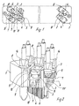
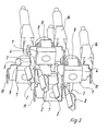
- the electrical connector has an insulating material 1. He has in the illustrated Embodiment arranged a plurality of in the insulating housing 1 Socket contacts 2, which are integral with connectors 3 to form the connector side Connections to the connection pieces 3 angled connection eyelets 4 are performed, which are associated with terminal screws 5, for below the connection eyes 4, inserted into a recess 6 of the insulating material 1, Nuts 7 are arranged. At the connection eyelets 4 can with the help of the terminal screws 5, as explained in detail below, optionally various conductor connection elements be determined.
- socket contacts 2 instead of the socket contacts 2 also plug contacts may be provided, which then according to connectors electrically connected to the connector-side terminals are.
- connection eyes 4 and the connection screws 5 in insulating material in two rows next to each other, with the connections of the two rows lie substantially parallel to the narrow side of the connector.
- the connection eyes 4 with the terminal screws 5 are also in the insulating housing 1 formed on all sides closed connection chambers 8, wherein the two rows of the terminal chambers 8 in alignment with each other at an angle to Longitudinal axis of the connector are arranged.
- the view also shows that according to the same construction principle, three or even more rows of terminals 4, 5 with corresponding socket contacts. 2 in an electrical connector while ensuring the same benefits can be realized.
- connection eyes 4 via the connecting pieces 3 integral with the socket contacts 2 are connected, are in a further advantageous embodiment according to formed at the top angled tabs 9, which in small recesses 10 in the corresponding Wall regions of the terminal chambers 8 can occur.
- connection eyelets 4 are further downwardly directed locking tabs 11 integrally formed with latch corresponding adjacent wall portions 12 of the terminal chambers 8 or can get caught.
- connection eyelets 4 are also downwardly directed locking tabs 11 integrally formed with latch corresponding adjacent wall portions 12 of the terminal chambers 8 or can get caught.
- the connector 3 are also notches 11 'formed, which secure this area of contact fix.
- the electrically conductive composite from socket contact 2 with connector 3 and connection eye 4 is thus multiple positive and positive in the Insulated housing fixed and locked and thus after assembly against Loss secured, without that about the terminal screws 5 used Need to become.
- the terminal screws are also 5 and the nuts 7 with the intermediate connection eye 4 a plane one above the other Composite, in particular between these parts no Wall sections of the insulating material are located. The danger of relaxation of the Plastic with the possibility of loosening the screw is so avoided.
- the view of the arrangement also shows that the above-mentioned metal parts advantageously assembled together from one direction, d. H. in the insulating material housing 1 can be introduced.
- FIGS. 4 and 5 show various possible embodiments of conductor connection elements, and once these diverse conductor connection elements as such in detail, on the other hand after their determination at the connection eyes 4 and thus the socket contacts 2 by means of the terminal screws 6.
- Figure 4 shows a Ring cable single connection 13 and a ring cable double connection 14. Ring cable connections are often preferred in this field of application and can be special comfortable and reliable here with the connection screws 5 on the plane lying connection eyes 4 are set.
- Figure 4 also illustrates that, if necessary also the conductors 15 to be connected as such after stripping their ends can be set directly with the help of the terminal screws 5, namely also in the manner of a double connection.
- FIG. 5 shows that flat plug-in individual terminals are also used as conductor connection elements 16 and flat plug-in double terminals 17 can be used, but also single wire wound connections 18 or Double Wire Wrap Connections 19. From Above shows that here all the advantages of a connector with an outermost Flexibility of the connection techniques for connecting external conductors is combined.
Landscapes
- Connector Housings Or Holding Contact Members (AREA)
- Details Of Connecting Devices For Male And Female Coupling (AREA)
- Coupling Device And Connection With Printed Circuit (AREA)
- Connections By Means Of Piercing Elements, Nuts, Or Screws (AREA)
Description
- Figur 1
- eine verkürzte Frontansicht eines Steckverbinders gemäß der Erfindung,
- Figur 2
- eine perspektivische Teilschnittdarstellung durch den Steckverbinder nach Figur 1,
- Figur 3
- eine weitere Teilansicht des Steckverbinders in Perspektive unter Fortlassung des Isolierstoffgehäuses,
- Fig. 4 u. 5
- diverse Ausführungsformen von mit einem derartigen Steckverbinder kombinierbaren Leiteranschlußelementen.
Claims (10)
- Elektrischer Steckverbinder mita) einem Isolierstoffgehäuse (1)mit einer längeren Seite und einer kürzeren Seite, undb) mit Kontakten (2), die einstückig mit Verbindungsstücken (3) zur Bildung von Anschlüssen zu Anschlußschrauben (5) geführt sind,c) wobei die Anschlüsse (4, 5) in mindestens zwei Anschlussreihen im Isolierstoffgehäuse (1) angeordnet sind, wobeid) die mindestens zwei Anschlussreihen im wesentlichen parallel zur längeren Seite liegen, dadurch gekennzeichnet, dasse) die Anschlüsse (4, 5) der mindestens zwei Anschlussreihen in in Lateralrichtung geschlossenen Anschlusskammern (8) angeordnet sind, die zur Aufnahme von Doppelanschlusselementen (14, 17, 19) zum Anschließen von von außen ankommenden Leiten dimensioniert sind,f) die Anschlusskammern (8) der mindestens zwei Anschlussreihen schräg zu den Anschlussreihen ausgerichtet sind, wobei jeweils Anschlusskammern (8) aus den wenigstens zwei Anschlussreihen miteinander fluchten.
- Steckverbinder nach Anspruch 1, dadurch gekennzeichnet, daß die Kontakte (2) über die Verbindungsstücke (3) mit vom anderen Ende der Verbindungsstücke (3) abgewinkelten Anschlußösen (4) verbunden sind.
- Steckverbinder nach Anspruch 2, dadurch gekennzeichnet, daß die Anschlußösen (4) auf Muttern (7) für die Anschlußschrauben (5) angeordnet sind, wobei die Muttern (7) ihrerseits in Aussparungen (6) des Isolierstoffgehäuses (1) abgestützt sind.
- Steckverbinder nach einem der Ansprüche 2 oder 3, dadurch gekennzeichnet, daß an die Anschlußösen (4) nach oben vorstehende Laschen (9) vorgesehen sind, für die in der angrenzenden Isolierstoffwandung Ausnehmungen (10) vorgesehen sind.
- Steckverbinder nach einem der Ansprüche 2 - 4, dadurch gekennzeichnet, daß an die Anschlußösen (4) nach unten vorstehende Rastlaschen (11) angeformt sind, die mit angrenzenden Wandabschnitten (12) des Isolierstoffgehäuses verrastbar sind.
- Steckverbinder nach Anspruch 1, dadurch gekennzeichnet, daß zur Verbindung mit dem steckverbinderseitigen Anschluß (4, 5) in den Anschlußkammern (8) als Leiteranschlußelemente Ringkabelanschlüsse sowohl als Einzelanschlüsse (13) wie als Doppelanschlüsse (14) vorgesehen sind.
- Steckverbinder nach Anspruch 1, dadurch gekennzeichnet, daß zur Verbindung mit den steckverbinderseitigen Anschlüssen (4, 5) in den Anschlußkammern (8) als Leiteranschlußelemente Flachsteckeinzelanschlüsse (16) sowie Flachsteckdoppelanschlüsse (17) vorgesehen sind.
- Steckverbinder nach Anspruch 1, dadurch gekennzeichnet, daß zur Verbindung mit den steckerseitigen Anschlüssen (4, 5) in den Anschlußkammern (8) als Leiteranschlußelement Einzel-Drahtwickelanschlüsse (18) sowie Doppel-Drahtwickelanschlüsse (19) vorgesehen sind.
- Steckverbinder nach Anspruch 1, dadurch gekennzeichnet, daß Flachsteckeinzelanschlüsse und Flachsteckdoppelanschlüsse einstückig mit dem Kontakt verbunden sind.
- Steckverbinder nach Anspruch 1 oder 2, dadurch gekennzeichnet, daß an dem Verbindungsstück (3) seitliche Rasten (11') angeformt sind.
Applications Claiming Priority (2)
| Application Number | Priority Date | Filing Date | Title |
|---|---|---|---|
| DE29712858U DE29712858U1 (de) | 1997-07-21 | 1997-07-21 | Elektrischer Steckverbinder |
| DE29712858U | 1997-07-21 |
Publications (3)
| Publication Number | Publication Date |
|---|---|
| EP0893849A2 EP0893849A2 (de) | 1999-01-27 |
| EP0893849A3 EP0893849A3 (de) | 1999-09-15 |
| EP0893849B1 true EP0893849B1 (de) | 2005-01-12 |
Family
ID=8043407
Family Applications (1)
| Application Number | Title | Priority Date | Filing Date |
|---|---|---|---|
| EP98103889A Expired - Lifetime EP0893849B1 (de) | 1997-07-21 | 1998-03-05 | Elektrischer Steckverbinder |
Country Status (3)
| Country | Link |
|---|---|
| EP (1) | EP0893849B1 (de) |
| DE (2) | DE29712858U1 (de) |
| ES (1) | ES2232892T3 (de) |
Families Citing this family (1)
| Publication number | Priority date | Publication date | Assignee | Title |
|---|---|---|---|---|
| NL1040319C2 (en) * | 2013-07-30 | 2015-02-02 | Georg Kalman Kaposvari | Electrical connector and vehicle provided therewith. |
Family Cites Families (11)
| Publication number | Priority date | Publication date | Assignee | Title |
|---|---|---|---|---|
| FR1325863A (fr) * | 1962-03-24 | 1963-05-03 | App Thermoflex Etablissements | Dispositif de connexion |
| DE1972559U (de) * | 1966-06-22 | 1967-11-16 | Hans Simon | Elektrische anschlussleiste. |
| CA981354A (en) * | 1972-06-14 | 1976-01-06 | Milton J. Weitzman | Terminal for electrically connecting an aluminum wire |
| US4273408A (en) * | 1979-02-21 | 1981-06-16 | General Electric Company | Terminal block assembly |
| DE3113676C2 (de) * | 1981-04-04 | 1986-04-03 | Brown, Boveri & Cie Ag, 6800 Mannheim | Anschlußvorrichtung für elektrische Leiter |
| FR2508721A1 (fr) * | 1981-06-30 | 1982-12-31 | Alsthom Cgee | Dispositif adaptateur pour connecteur electrique femelle |
| CH656024A5 (en) * | 1981-08-18 | 1986-05-30 | Landis & Gyr Ag | Plug-in terminal base for multipole male plug connector strips |
| DE3644153C2 (de) * | 1986-12-23 | 1994-06-23 | Asea Brown Boveri | Verbinderanordnung für die Herstellung einer elektrischen Leitungsverbindung |
| ES1026401Y (es) * | 1993-11-26 | 1995-04-01 | Mecanismos Aux Ind | Sistema modular de conectores. |
| GB9400021D0 (en) * | 1994-01-04 | 1994-03-02 | Amp Gmbh | Panel mount connector |
| DE29520008U1 (de) * | 1995-12-16 | 1996-03-07 | Harting Elektronik Gmbh, 32339 Espelkamp | Elektrischer Steckverbinder |
-
1997
- 1997-07-21 DE DE29712858U patent/DE29712858U1/de not_active Expired - Lifetime
-
1998
- 1998-03-05 EP EP98103889A patent/EP0893849B1/de not_active Expired - Lifetime
- 1998-03-05 ES ES98103889T patent/ES2232892T3/es not_active Expired - Lifetime
- 1998-03-05 DE DE59812480T patent/DE59812480D1/de not_active Expired - Lifetime
Also Published As
| Publication number | Publication date |
|---|---|
| EP0893849A3 (de) | 1999-09-15 |
| EP0893849A2 (de) | 1999-01-27 |
| DE59812480D1 (de) | 2005-02-17 |
| ES2232892T3 (es) | 2005-06-01 |
| DE29712858U1 (de) | 1997-09-25 |
Similar Documents
| Publication | Publication Date | Title |
|---|---|---|
| DE69020827T2 (de) | Steckvorrichtung für Einspritzdüsen für eine Brennkraftmaschine und dabei verwendetes Kontaktelement. | |
| DE69421798T2 (de) | Verbinder vom Typ Modular Jack | |
| DE69421760T2 (de) | Elektrischer Verbinder für Flachkabel mit hoher Dichte | |
| DE4411187C2 (de) | Elektrisches Verbindersystem | |
| EP2206200A1 (de) | Reihenklemme mit einem verbinder | |
| DE69931430T2 (de) | Modularer Verbinder für hohe Übertragungsgeschwindigkeiten | |
| DE69328662T2 (de) | Filterverbinder hoher Dichte | |
| DE10251863A1 (de) | Stromverteilerkasten und Leistungsgerätemodul | |
| DE69917162T2 (de) | Elektrische Verbindungsdose | |
| DE102009030645B4 (de) | Brückerelement und Set aus zumindest einem Klemmelement und Brückerelement | |
| DE69331910T2 (de) | Ein verbinder mit verbesserter abschirmung | |
| DE102019102011A1 (de) | Kontakt- und Busschienenanordnung | |
| EP0774800B1 (de) | Querverbinder für Reihenklemmen | |
| DE4106412C2 (de) | Elektrischer Steckverbinder | |
| DE69204161T2 (de) | Abgeschirmeter verbinder mit isolationsverdrängungsklemmen und gestevertem impedanzverhalten. | |
| DE4038362A1 (de) | Anschlussklemme fuer elektrische leiter | |
| DE2750540C2 (de) | ||
| EP0945929B1 (de) | Steckverbinder für ein geschirmtes Kabel | |
| AT399427B (de) | Audio-buchsen-stecker | |
| DE69612936T2 (de) | Steckdosenbox | |
| DE60208260T2 (de) | Verbesserte Sammelschiene mit isolierten Anschlüssen und zugehöriger Steckverbinderführung | |
| DE19519634C2 (de) | Anschlußblock für Leistungskondensatoren | |
| DE19606050C2 (de) | Elektrischer Steckverbinder mit einem zweiteiligen, abgeschirmten Isoliergehäuse | |
| DE9215527U1 (de) | Verbindungsstück für Stromschienen | |
| DE2617172B2 (de) | Anschlussblock fuer kabelenden, insbesondere fuer fernmeldekabel |
Legal Events
| Date | Code | Title | Description |
|---|---|---|---|
| PUAI | Public reference made under article 153(3) epc to a published international application that has entered the european phase |
Free format text: ORIGINAL CODE: 0009012 |
|
| 17P | Request for examination filed |
Effective date: 19980305 |
|
| AK | Designated contracting states |
Kind code of ref document: A2 Designated state(s): CH DE ES FR GB IT LI |
|
| AX | Request for extension of the european patent |
Free format text: AL;LT;LV;MK;RO;SI |
|
| PUAL | Search report despatched |
Free format text: ORIGINAL CODE: 0009013 |
|
| AK | Designated contracting states |
Kind code of ref document: A3 Designated state(s): AT BE CH DE DK ES FI FR GB GR IE IT LI LU MC NL PT SE |
|
| AX | Request for extension of the european patent |
Free format text: AL;LT;LV;MK;RO;SI |
|
| AKX | Designation fees paid |
Free format text: CH DE ES FR GB IT LI |
|
| 17Q | First examination report despatched |
Effective date: 20030626 |
|
| GRAP | Despatch of communication of intention to grant a patent |
Free format text: ORIGINAL CODE: EPIDOSNIGR1 |
|
| GRAS | Grant fee paid |
Free format text: ORIGINAL CODE: EPIDOSNIGR3 |
|
| GRAA | (expected) grant |
Free format text: ORIGINAL CODE: 0009210 |
|
| AK | Designated contracting states |
Kind code of ref document: B1 Designated state(s): CH DE ES FR GB IT LI |
|
| REG | Reference to a national code |
Ref country code: GB Ref legal event code: FG4D Free format text: NOT ENGLISH |
|
| REG | Reference to a national code |
Ref country code: CH Ref legal event code: NV Representative=s name: ISLER & PEDRAZZINI AG Ref country code: CH Ref legal event code: EP |
|
| REF | Corresponds to: |
Ref document number: 59812480 Country of ref document: DE Date of ref document: 20050217 Kind code of ref document: P |
|
| GBT | Gb: translation of ep patent filed (gb section 77(6)(a)/1977) |
Effective date: 20050405 |
|
| REG | Reference to a national code |
Ref country code: ES Ref legal event code: FG2A Ref document number: 2232892 Country of ref document: ES Kind code of ref document: T3 |
|
| PLBE | No opposition filed within time limit |
Free format text: ORIGINAL CODE: 0009261 |
|
| STAA | Information on the status of an ep patent application or granted ep patent |
Free format text: STATUS: NO OPPOSITION FILED WITHIN TIME LIMIT |
|
| ET | Fr: translation filed | ||
| 26N | No opposition filed |
Effective date: 20051013 |
|
| REG | Reference to a national code |
Ref country code: CH Ref legal event code: PCAR Free format text: ISLER & PEDRAZZINI AG;POSTFACH 1772;8027 ZUERICH (CH) |
|
| PGFP | Annual fee paid to national office [announced via postgrant information from national office to epo] |
Ref country code: ES Payment date: 20130326 Year of fee payment: 16 Ref country code: CH Payment date: 20130322 Year of fee payment: 16 |
|
| PGFP | Annual fee paid to national office [announced via postgrant information from national office to epo] |
Ref country code: IT Payment date: 20140325 Year of fee payment: 17 |
|
| REG | Reference to a national code |
Ref country code: CH Ref legal event code: PL |
|
| PG25 | Lapsed in a contracting state [announced via postgrant information from national office to epo] |
Ref country code: CH Free format text: LAPSE BECAUSE OF NON-PAYMENT OF DUE FEES Effective date: 20140331 Ref country code: LI Free format text: LAPSE BECAUSE OF NON-PAYMENT OF DUE FEES Effective date: 20140331 |
|
| PG25 | Lapsed in a contracting state [announced via postgrant information from national office to epo] |
Ref country code: IT Free format text: LAPSE BECAUSE OF NON-PAYMENT OF DUE FEES Effective date: 20150305 |
|
| REG | Reference to a national code |
Ref country code: FR Ref legal event code: PLFP Year of fee payment: 19 |
|
| REG | Reference to a national code |
Ref country code: ES Ref legal event code: FD2A Effective date: 20160426 |
|
| PG25 | Lapsed in a contracting state [announced via postgrant information from national office to epo] |
Ref country code: ES Free format text: LAPSE BECAUSE OF NON-PAYMENT OF DUE FEES Effective date: 20150306 |
|
| REG | Reference to a national code |
Ref country code: FR Ref legal event code: PLFP Year of fee payment: 20 |
|
| PGFP | Annual fee paid to national office [announced via postgrant information from national office to epo] |
Ref country code: FR Payment date: 20170322 Year of fee payment: 20 Ref country code: DE Payment date: 20170322 Year of fee payment: 20 |
|
| PGFP | Annual fee paid to national office [announced via postgrant information from national office to epo] |
Ref country code: GB Payment date: 20170322 Year of fee payment: 20 |
|
| REG | Reference to a national code |
Ref country code: DE Ref legal event code: R071 Ref document number: 59812480 Country of ref document: DE |
|
| REG | Reference to a national code |
Ref country code: GB Ref legal event code: PE20 Expiry date: 20180304 |
|
| PG25 | Lapsed in a contracting state [announced via postgrant information from national office to epo] |
Ref country code: GB Free format text: LAPSE BECAUSE OF EXPIRATION OF PROTECTION Effective date: 20180304 |