EP0885696B1 - Rasoir électrique - Google Patents
Rasoir électrique Download PDFInfo
- Publication number
- EP0885696B1 EP0885696B1 EP98110686A EP98110686A EP0885696B1 EP 0885696 B1 EP0885696 B1 EP 0885696B1 EP 98110686 A EP98110686 A EP 98110686A EP 98110686 A EP98110686 A EP 98110686A EP 0885696 B1 EP0885696 B1 EP 0885696B1
- Authority
- EP
- European Patent Office
- Prior art keywords
- formation region
- blade formation
- slit
- blade
- outermost
- Prior art date
- Legal status (The legal status is an assumption and is not a legal conclusion. Google has not performed a legal analysis and makes no representation as to the accuracy of the status listed.)
- Expired - Lifetime
Links
Images


Classifications
-
- B—PERFORMING OPERATIONS; TRANSPORTING
- B26—HAND CUTTING TOOLS; CUTTING; SEVERING
- B26B—HAND-HELD CUTTING TOOLS NOT OTHERWISE PROVIDED FOR
- B26B19/00—Clippers or shavers operating with a plurality of cutting edges, e.g. hair clippers, dry shavers
- B26B19/14—Clippers or shavers operating with a plurality of cutting edges, e.g. hair clippers, dry shavers of the rotary-cutter type; Cutting heads therefor; Cutters therefor
- B26B19/143—Details of outer cutters
-
- B—PERFORMING OPERATIONS; TRANSPORTING
- B26—HAND CUTTING TOOLS; CUTTING; SEVERING
- B26B—HAND-HELD CUTTING TOOLS NOT OTHERWISE PROVIDED FOR
- B26B19/00—Clippers or shavers operating with a plurality of cutting edges, e.g. hair clippers, dry shavers
- B26B19/14—Clippers or shavers operating with a plurality of cutting edges, e.g. hair clippers, dry shavers of the rotary-cutter type; Cutting heads therefor; Cutters therefor
- B26B19/141—Details of inner cutters having their axes of rotation perpendicular to the cutting surface
-
- B—PERFORMING OPERATIONS; TRANSPORTING
- B26—HAND CUTTING TOOLS; CUTTING; SEVERING
- B26B—HAND-HELD CUTTING TOOLS NOT OTHERWISE PROVIDED FOR
- B26B19/00—Clippers or shavers operating with a plurality of cutting edges, e.g. hair clippers, dry shavers
- B26B19/38—Details of, or accessories for, hair clippers, or dry shavers, e.g. housings, casings, grips, guards
- B26B19/384—Dry-shaver foils; Manufacture thereof
Definitions
- the present invention relates to a rotary type electric shaver.
- an electric shaver is equipped with at least one shaving unit 54 that consists of a circular outer cutter unit 50 and a circular inner cutter unit 52 which is rotated relative to the outer cutter unit 50.
- the outer cutter unit 50 is provided with two annular blade formation regions 56a and 56b, and a plurality of hair-entry slits 62a and 62b of the same width are formed so as to be side by side in the circumferential direction and extend in substantially radial configuration, thus forming slit-form blades 58a and 58b in the annular blade formation regions 56a and 56b.
- the side walls of the ribs 64a which are formed by two adjacent slits 62a of the outer blade formation region 56a act as blade surfaces for cutting whiskers; and likewise, for the inner slit-form blades 58b, the side walls of the ribs 64b which are formed by two adjacent slits 62b of the inner blade formation region 56b act as blade surfaces for cutting the whiskers.
- the term "substantially radial configuration" described above refers to the fact that the respective slits 62a and 62b are formed in a straight line so that the slits extend from the inner circumferences of the respective blade formation regions 56a and 56b to the outer circumferences of the blade formation regions with the slits inclined at a prescribed angle with respect to the radial direction extending from the center of each of the outer cutter units 50.
- the "prescribed angle” refers to an angle in the range of 0 degrees to 90 degrees (e. g., about 10 degrees). The same is true below.
- the respective slits 62a and 62b are formed in the respective blade formation regions 56a and 56b at equal angular (angle ⁇ ) intervals.
- the inner cutter unit 50 is provided with inner blade bodies 60 which are disposed circumferentially.
- the tip ends of the respective inner blade bodies 60 are bifurcated as shown in Figure 11, thus forming inner blade elements 60a and 60b which respectively contact the internal surfaces of the slit-form blades 58a and 58b.
- These inner blade elements 60a and 60b are arranged in concentric annular configurations so as to correspond to the annular blade formation regions 56a and 56b of the outer cutter unit 50.
- the slit-form blade 58a and inner blade elements 60a form an annular cutting blade assembly located around the outer circumference of the shaving unit 54
- the slit-form blade 58b and inner blade elements 60b form another cutting blade assembly located around the inner circumference of the shaving unit 54.
- the tip ends of the respective inner blade elements 60a and 60b of the inner cutter unit 52 which rotate while contacting the interior surfaces of the slit-form blades 58a and 58b, are also formed so as to be positioned on the same plane X.
- the slits 62a and 62b of the respective slit-form blades 58a and 58b of the outer cutter unit 50 extend from the inner circumferences to the outer circumferences of the respective blade formation regions 56a and 56b in a substantially radial configuration. Furthermore, the respective widths of the inner and outer blade formation regions 56a and 56b must be a certain predetermined size or greater in order to obtain a maximum possible effective shaving area created by the corresponding inner blade elements 60a and 60b. Accordingly, the slits 62a and 62b are generally greater in length than the holes formed in a foil blade of reciprocating type electric shavers. Moreover, the widths d of the slits 62a and 62b must also have a prescribed size or greater in order to effectively introduce whiskers thereinto.
- the respective slits 62a and 62b are inevitably formed large, and this results in that the skin tends to enter into these slits during shaving. Accordingly, it is necessary to form the slit-form blades 58a and 58b with a certain thickness so that the skin entering the slits 62a and 62b does not reach the inner cutter unit 52 and cause cutting injuries.
- shaving is done by holding the electric shaver in one hand and pressing it against the surface of the skin, moving the shaving unit 54 around on the skin; accordingly, the skin in contact with the area of the side-surface opening on the outer circumferential side of the slit-form blade 58a of the blade formation region 56a located at the outermost circumference of the outer cutter unit 50, tends to wrinkle up and easily enters the slits as indicated by arrows A.
- the thickness a of the slit-form blades 58a of the outermost blade formation region 56a must have a certain predetermined thickness in order to insure the safety of the user; and as a result, the thickness b of the slit-form blades 58b of the inner blade formation region 56b correspondingly has a certain thickness so as to conform with the thickness a .
- WO 97/45235 discloses a shaver with slit-form blades of different thickness. However, the slits forming the slit-form blades extend circumferentially.
- the present invention is to solve the problems described above, and the object of the present invention is to provide an electric shaver which allows deep shaving of whiskers without damaging the skin of the user even with the use of an outer cutter unit that has a slit-form blade.
- an electric shaver which includes outer cutter units each of which is provided with a blade formation region of an annular shape with slit-form blades formed therein and inner cutter units each comprising a plurality of inner blade elements arranged in an annular configuration with tip ends contacting the interior surface of the slit-form blades of the outer cutter units while being rotated relative to the outer cutter units; and the electric shaver is characterized in that a plurality of the blade formation regions are formed in the shape of concentric circles in each of the outer cutter units, and the slit-form blades of the blade formation regions other than the outermost blade formation region are formed thinner than those of the outermost blade formation region.
- the slit-form blades in the outermost blade formation region of the outer cutter unit are thicker than that of other blade formation region(s), and therefore, the safety of the user is insured when the outer cutter units are moved while being pressed against the skin during shaving; and at the same time, since the slit-form blades of the blade formation region(s) other than the outermost blade formation region is thinner than those of the outermost blade formation region, the deep shaving of whiskers can be accomplished.
- each one of the ribs, which are formed by two adjacent slits, in the blade formation region(s) other than the outermost blade formation region can have a larger circumferential width when compared to the ribs formed by slits in the same number in each blade formation region; as a result, the ribs have a larger cross-sectional area, and the strength of the outer cutter units can be assured.
- the slits and ribs of the blade formation region(s) other than the outermost blade formation region can be shorter than those of the outermost blade formation region.
- the amount of bending of the ribs in the radial direction in such region(s) decreases, and deformation of the outer cutter units during shaving can be reduced.
- the strength of the outer cutter units can be insured.
- the slit-form blades formed in the outermost blade formation region has the greatest amount of protrusion, while the slit-form blades formed in the blade formation region(s) other than the outermost blade formation region is in a slightly recessed form. Accordingly, tight contact with the skin of the face, which is a curving surface, can be assured; and in addition, since the height of the tip end of the plurality of inner blade elements of the inner cutter units does not need to be different, the inner cutter units can be manufactured without any complexity.
- the thickness of the slit-form blades formed in at least one of the blade formation regions other than the outermost blade formation region is substantially the same as that of a foil blade used in a reciprocating electric shaver, and deep shaving of whiskers can be accomplished in a favorable manner.
- an electric shaver which includes outer cutter units each of which is provided with a blade formation region of an annular shape with slit-form blades formed therein and inner cutter units each comprising a plurality of inner blade elements arranged in an annular configuration with tip ends that contact the interior surface of the slit-form blades of the outer cutter units while being rotated relative to the outer cutter units, and wherein a plurality of the blade formation regions are formed in the shape of concentric circles in each of the outer cutter units, and slits that comprise the slit-form blades of the blade formation regions other than the outermost blade formation region have widths in the circumferential direction greater than slits formed in the outermost blade formation region.
- an electric shaver has three shaving units each comprising a circular outer cutting unit 14 and a circular inner cutting unit 18; however, the same description is applicable to an electric shaver which has one or two shaving units, or an electric shaver which has four or more shaving units.
- the upper portion of the electric shaver 10 in Figure 1 is a shaver head 12; and three shaving units 16 are provided therein (only two clearly shown) so that outer cutter units 14 thereof are exposed out of the shaver head 12.
- the electric shaver 10 further includes a housing 22 which is made of a synthetic resin.
- the housing 22 contains therein a driving mechanism 20 for inner cutter units 18, an electric motor 24 located beneath the shaver head 12 so as to actuate the driving mechanism 20, a battery 26 which supplies electric current to the electric motor 24, a connector 28 installed in the lower end of the housing 22 so as to supply a charging current to the battery 26 from outside, and a slide switch 30 provided on the front of the housing 22 so as to be used to switch the current supply from the battery 26 to the electric motor 24 on and off.
- the upper end of the shaver head 12 is open and is covered by a detachable head frame 32 which is snap-fitted to the housing 22.
- a cutter retainer frame 36 is removably attached to the interior surface of the head frame 32 by an attachment screw 34 so that the outer cutter units 14 and the inner cutter units 18 are held between the cutter retainer frame 36 and the head frame 32, thus preventing these cutter units falling off of the shaver head 12.
- coupling elements 40 are attached to the central portions of the inner cutter units 18.
- the coupling elements 40 made of a synthetic resin, are engaged with the tip ends of drive shafts 38 (constituting a part of the driving mechanism 20) so that the inner cutter units 18 are rotated by the drive shafts 38.
- the tip ends (upper ends in Figure 2) of these coupling elements 40 are loosely inserted into tubular portions 42a formed in the undersurfaces of disk members 42 securely attached to the central portions of the outer cutter units 14, and the centers of the inner and outer cutters 18 and 14 are thus axially aligned.
- the drive shafts 38 constantly urge the inner cutter units 18 upward (or toward the outer cutter units 14) by springs (not shown).
- the rotational force of the electric motor 24 is transmitted to the drive shafts 38 by a transmission mechanism (not shown) which comprises a gear mechanism, etc. and constitutes a part of the driving mechanism 20.
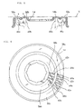
- two blade formation regions 56a and 56b of annular shape are formed concentrically in each one of the outer cutter units 14; and a plurality of slits 62a and 62b of the same width in the circumferential direction are formed so as to extend substantially in a radial direction in the respective blade formation regions 56a and 56b, so that slit-form blades 58a and 58b are formed in the blade formation regions 56a and 56b.
- the side walls of each one of the ribs 64a formed by two adjacent slits 62a of the outermost blade formation region 56a act as blade surfaces for cutting whiskers; and likewise, for the slit-form blades 58b, the side walls of each one of the ribs 64b formed by two adjacent slits 62b of the inside blade formation region 56b act as blade surfaces for cutting whiskers as seen from Figure 3.
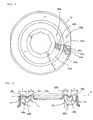
- the inner cutter unit 18 has a plurality of inner blade bodies 60 (only two are shown in Figure 4) which are disposed circumferentially.
- the tip ends of the respective inner blade bodies 60 are bifurcated so as to form inner blade elements 60a and 60b which contact the interior surfaces of the slit-form blades 58a and 58b, respectively.
- the respective inner blade elements 60a and 60b are disposed in concentric annular configurations so as to correspond to the blade formation regions 56a and 56b which are also in concentric annular configurations.
- the slit-form blades 58a and inner blade elements 60a form an outside annular cutting blade assembly which is located around the outer circumference of each circular shaving unit 16, and the slit-form blades 58b and inner blade elements 60b form an inside cutting blade assembly which is located around the inner circumference of each circular shaving unit 16 as shown in Figure 4.
- the thickness b of the slit-form blades 58b formed in the inside blade formation region 56b is designed so as to be smaller than the thickness a of the slit-form blades 58a formed in the outermost blade formation region 56a ( a > b ).
- a thickness of 0.04 mm to 0.07 mm which is approximately the same thickness as that of a foil blade, is preferable for the thickness b of the slit-form blades 58b of the inside blade formation region 56b.
- the interior surfaces of the slit-form blades 58a and 58b of the respective blade formation regions 56a and 56b are formed so that these interior surfaces are all positioned on the same plane X.
- the slit-form blades 58a formed in the blade formation region 56a positioned at the outermost circumference of each outer cutter unit 14 (where entry of the skin is most likely) remain as thick as that of conventional electric shavers, the safety of the user is insured when the outer cutter units 14 are moved around while being pressed against the surface of the skin 44 during shaving; at the same time, since the slit-form blades 58b in the inside blade formation region 56b are formed as thin as a foil blade, deep shaving of whiskers can be accomplished by these slit-form blades 58b. Thus, the deep shaving of whiskers can be realized using the electric shaver 10 as a whole.
- the slit-form blades 58a of the outermost blade formation region 56a have the greatest amount of protrusion, while the slit-form blades 58b located inner side thereof are slightly lower compared to the slit-form blades 58a. Accordingly, tight contact to the skin 44 of the face of the user, which is a curving surface, is enhanced, thus assuring efficient shaving.
- the interior surfaces of the respective slit-form blades 58a and 58b of each outer cutter unit 14 are formed so as to be all positioned on the same plane X.
- the height of the tip ends of the plurality of inner blade elements 60a and 60b of the inner cutter unit 18 varies so as to contact the interior surfaces of the slit-form blades 58a and 58b, and the inside blade elements 60b have a greater amount of height than the outside blade elements 60a.
- the strength of the inside blade formation region 56b of the outer cutter unit 14 may drop compared to the strength obtained in a conventional electric shaver. So as to compensate this, as shown in the embodiment of Figure 6, the inside blade formation region 56b is formed with a smaller number of slits 62b compared to the outermost blade formation region 56a.
- the width of the ribs 64b in the circumferential direction of the inside blade formation region 56b increases accordingly; as a result, a greater cross-sectional area is obtained for the ribs 64b of the inside blade formation region 56b compared to a case in which the same number of slits 62a and 62b are formed in the blade formation regions 56a and 56b.
- the strength of the inside blade formation region 56b increases, and the strength of the outer cutter unit 14 as a whole can be insured.
- the number of slits 62b of the inside blade formation region 56b is set so as to be, for instance, half the number of the slits 62a of the outermost blade formation region 56a.
- this ratio may be selected as desired in accordance with the radial width of the blade formation region 56b, width d of the slits 62b and the thickness of the outer cutter unit 14, etc.
- the width e of the inside blade formation region 56b in the radial direction may be made smaller than the width f of the outermost blade formation region 56a in order to avoid a drop in the strength of the outermost blade formation region 56b of each outer cutter unit 14.
- the thickness b of the inside slit-form blades 58b which is reduced does not cause the amount of bending of the ribs 64b in the radial direction to increase, and therefore, deformation of the outer cutter unit 14 during shaving can be reduced. Accordingly, the strength of the outer cutter unit 14 can be insured.
- the width d of the slits 62b of the inside blade formation region 56b in the circumferential direction is set to be larger than the width d of the slits 62a of the outermost blade formation region 56a.
- the blade formation regions of the outer cutter units 14 and the inner blade elements of the inner cutter units 18 are formed in a dual annular configuration; however, the same construction can be employed even in cases where the slit-form blades and inner blade elements are formed in a multiple configuration such as a triple, quadruple or even greater multiple annular configurations.
- a plurality of blade formation regions are formed in the outer cutter unit, it is sufficient if the slit-form blades of the blade formation region(s) other than the outermost blade formation region, i. e., the blade formation regions located near the center, are formed thinner than the slit-form blades of the outermost blade formation region or have wider slits than those of the outermost blade formation region.
- the electric shaver of the present invention when the outer cutter units are moved while being pressed against the surface of the skin during shaving, the safety of the user is insured since the slit-form blades formed in the blade formation region located at the outermost circumference of each outer cutter unit, where entry of the skin is most likely, is formed thicker than other slit-form blades; and at the same time, the thickness of the slit-form blades in the other blade formation region(s) is made smaller so that deep shaving of whiskers can be accomplished.
- the slit-form blades of the outermost blade formation region of each outer cutter unit have the greatest amount of protrusion, and the slit-form blades in other blade formation regions located near the center of the outer cutter unit are slightly depressed; accordingly, tight contact to the skin of the face, which has curved surfaces, is enhanced; and efficient shaving can be accomplished.
Claims (9)
- Rasoir électrique comprenant une unité coupante extérieure (14) munie d'une pluralité de fentes (62a, 62b) qui forment des lames (58a, 58b) en forme de fentes qui s'étendent essentiellement en direction radiale dans une zone de formation de lames (56a, 56b) d'une forme annulaire et une unité coupante intérieure (16) munie d'une pluralité d'éléments de lame intérieurs (60) disposés dans une configuration annulaire dont les extrémités de pointe font contact avec les surfaces intérieures desdites lames en forme de fentes (58a, 58b) et sont tournées par rapport à ladite unité coupante extérieure (14), dans lequel une pluralité desdites zones de formation de lames (56a, 56b) sont formées dans une forme de cercles concentriques dans ladite unité coupante extérieure (14), caractérisé en ce qu'une épaisseur desdites lames en forme de fentes (58b) dans une zone de formation de lames (56b) autre qu'une zone de formation de lames (56a) la plus à l'extérieur est réalisée plus petite qu'une épaisseur desdites lames en forme de fentes (58a) dans ladite zone de formation de lames (56a) la plus à l'extérieur.
- Rasoir électrique selon la revendication 1, dans lequel lesdites fentes (62b) desdites lames en forme de fentes (58b) dans ladite zone de formation de lames (56b) autre que ladite zone de formation de lames (56a) la plus à l'extérieur sont inférieures en nombre aux dites fentes (62a) desdites lames en forme de fentes (58a) dans ladite zone de formation de lames (56a) la plus à l'extérieur.
- Rasoir électrique selon l'une des revendications 1 ou 2, dans lequel ladite zone de formation de lames (56b) autre que ladite zone de formation de lames (56a) la plus à l'extérieur est plus petite en largeur en direction radiale que ladite zone de formation de lames (56a) la plus à l'extérieur.
- Rasoir électrique selon l'une des revendications 1, 2 ou 3, dans lequel des surfaces intérieures desdites lames en forme de fentes (58a, 58b) formées dans lesdites zones de formation de lames (56a, 56b) sont positionnées sur un même plan.
- Rasoir électrique selon l'une des revendications 1, 2, 3 ou 4, dans lequel une épaisseur desdites lames en forme de fentes (58b) formées dans ladite zone de formation de lames (56b) autre que ladite zone de formation de lames (56a) la plus à l'extérieur est comprise entre 0,04 mm et 0,07 mm.
- Rasoir électrique selon l'une des revendications 1, 2 ou 3, dans lequel des surfaces extérieures desdites lames en forme de fentes (58a, 58b) formées dans lesdites zones de formation de lames (56a, 56b) sont positionnées sur un même plan.
- Rasoir électrique selon la revendication 6, dans lequel une épaisseur desdites lames en forme de fentes (58b) formées dans ladite zone de formation de lames (56b) autre que ladite zone de formation de lames (56a) la plus à l'extérieur est comprise entre 0,04 mm et 0,07 mm.
- Rasoir électrique selon l'une des revendications 1 ou 2, dans lequel lesdites fentes (62b) dans ladite zone de formation de lames (56b) autre que ladite zone de formation de lames (56a) la plus à l'extérieur sont plus grandes en largeur en direction circonférentielle que lesdites fentes (62a) dans ladite zone de formation de lames (56a) la plus à l'extérieur.
- Rasoir électrique selon l'une des revendications 1 à 8 comprenant au moins une unité coupante extérieure circulaire (14) munie d'une zone annulaire de formation de lames la plus à l'extérieur (56a) et au moins une zone annulaire de formation de lames à l'intérieur (56b) qui sont agencées de façon concentrique, chacune desdites zones annulaires de formation de lames étant formée par une pluralité de fentes (62a, 62b) qui s'étendent en direction radiale de ladite unité coupante extérieure circulaire (14), et au moins une unité coupante intérieure (14) munie d'une pluralité d'éléments de lame intérieurs (60) disposés dans une configuration annulaire dont les extrémités de pointe font contact avec les surfaces intérieures desdites lames en forme de fentes (58a, 58b) de ladite au moins une unité coupante extérieure (14) et sont tournées par rapport à ladite au moins une unité coupante extérieure (14), dans lequel chacune de ladite pluralité de fentes (62b) formées dans ladite au moins une zone de formation de lames à l'intérieur (56b) présente une largeur en direction circonférentielle plus grande que chacune de ladite pluralité de fentes (62a) formées dans ladite zone de formation de lames (56a) la plus à l'extérieur.
Applications Claiming Priority (3)
| Application Number | Priority Date | Filing Date | Title |
|---|---|---|---|
| JP159404/97 | 1997-06-17 | ||
| JP9159404A JPH114980A (ja) | 1997-06-17 | 1997-06-17 | 電気かみそり |
| JP15940497 | 1997-06-17 |
Publications (2)
| Publication Number | Publication Date |
|---|---|
| EP0885696A1 EP0885696A1 (fr) | 1998-12-23 |
| EP0885696B1 true EP0885696B1 (fr) | 2002-09-25 |
Family
ID=15693037
Family Applications (1)
| Application Number | Title | Priority Date | Filing Date |
|---|---|---|---|
| EP98110686A Expired - Lifetime EP0885696B1 (fr) | 1997-06-17 | 1998-06-10 | Rasoir électrique |
Country Status (7)
| Country | Link |
|---|---|
| US (1) | US6199282B1 (fr) |
| EP (1) | EP0885696B1 (fr) |
| JP (1) | JPH114980A (fr) |
| CN (1) | CN1079719C (fr) |
| CA (1) | CA2240565C (fr) |
| DE (1) | DE69808180T2 (fr) |
| HK (1) | HK1016923A1 (fr) |
Families Citing this family (28)
| Publication number | Priority date | Publication date | Assignee | Title |
|---|---|---|---|---|
| JP4519219B2 (ja) | 1999-06-21 | 2010-08-04 | 株式会社泉精器製作所 | 回転式電気かみそり |
| JP4519285B2 (ja) * | 2000-07-25 | 2010-08-04 | 株式会社泉精器製作所 | 回転式電気かみそりの内刃と回転式電気かみそり |
| JP2002052270A (ja) * | 2000-08-11 | 2002-02-19 | Izumi Products Co | 回転式電気かみそり |
| JP4635166B2 (ja) * | 2000-11-28 | 2011-02-16 | 株式会社泉精器製作所 | 回転式電気かみそり |
| EP1255628B1 (fr) * | 2000-12-06 | 2005-03-02 | Koninklijke Philips Electronics N.V. | Appareil de rasage |
| JP2002346250A (ja) * | 2001-05-22 | 2002-12-03 | Izumi Products Co | 回転式電気かみそり |
| CN1211190C (zh) * | 2002-09-09 | 2005-07-20 | 陈静静 | 多功能刀头 |
| JP2004141378A (ja) | 2002-10-24 | 2004-05-20 | Izumi Products Co | 電気かみそり |
| JP2004329479A (ja) * | 2003-05-06 | 2004-11-25 | Izumi Products Co | 回転式電気かみそり |
| JP2004350824A (ja) * | 2003-05-28 | 2004-12-16 | Izumi Products Co | 電気かみそりの外刃および電気かみそり |
| JP2005185827A (ja) * | 2003-12-03 | 2005-07-14 | Izumi Products Co | ロータリー式電気かみそり |
| EP1761367B1 (fr) * | 2004-06-21 | 2010-09-22 | Koninklijke Philips Electronics N.V. | Rasoir |
| ATE481219T1 (de) * | 2004-06-21 | 2010-10-15 | Koninkl Philips Electronics Nv | Rasierapparat |
| ES2621131T3 (es) * | 2004-11-01 | 2017-07-03 | Koninklijke Philips N.V. | Unidad cortadora para afeitadora rotativa y afeitadora rotativa provista de la misma |
| DE602005018389D1 (de) * | 2004-11-01 | 2010-01-28 | Koninkl Philips Electronics Nv | , damit ausgestatteter rasierkopf und rotationsrasierapparat |
| JP2006198093A (ja) | 2005-01-19 | 2006-08-03 | Izumi Products Co | ロータリー式電気かみそり |
| JP2006218217A (ja) * | 2005-02-14 | 2006-08-24 | Izumi Products Co | ロータリー式電気かみそり |
| JP2006223373A (ja) * | 2005-02-15 | 2006-08-31 | Izumi Products Co | ロータリー式電気かみそり |
| EP1927441A1 (fr) * | 2006-11-28 | 2008-06-04 | Koninklijke Philips Electronics N.V. | Capuchon au profil confortable prévu pour être appliqué sur la tête de rasage d'un rasoir |
| JP5578724B2 (ja) * | 2010-11-08 | 2014-08-27 | 株式会社泉精器製作所 | ロータリー式電気かみそり |
| JP5649214B2 (ja) * | 2010-11-08 | 2015-01-07 | 株式会社泉精器製作所 | ロータリー式電気かみそり |
| JP5649213B2 (ja) * | 2010-11-08 | 2015-01-07 | 株式会社泉精器製作所 | 電気かみそりの外刃および内刃の製造方法 |
| BR112014016698B1 (pt) * | 2012-01-10 | 2020-06-02 | Koninklijke Philips N.V. | Unidade de barbear; cortador rotativo para uma unidade de barbear; cápsula; e barbeador |
| EP2857155A1 (fr) * | 2013-10-01 | 2015-04-08 | Koninklijke Philips N.V. | Ensemble de lames et appareil de coupe de cheveux |
| EP2857158B1 (fr) * | 2013-10-01 | 2017-05-10 | Koninklijke Philips N.V. | Ensemble de lames et appareil de coupe de cheveux |
| JP6339417B2 (ja) * | 2014-05-30 | 2018-06-06 | 株式会社泉精器製作所 | ロータリー式電気かみそり |
| JP6517369B2 (ja) | 2015-05-21 | 2019-05-22 | コーニンクレッカ フィリップス エヌ ヴェKoninklijke Philips N.V. | シェービング装置の改善された切断ユニット及びシェービングヘッド |
| KR102009757B1 (ko) * | 2019-03-21 | 2019-08-12 | (주)싸이젠텍 | 인공지능 프로그램 기반 이물선별장치 |
Family Cites Families (5)
| Publication number | Priority date | Publication date | Assignee | Title |
|---|---|---|---|---|
| NL59158C (fr) * | 1942-01-13 | 1900-01-01 | ||
| DE909666C (de) * | 1942-11-04 | 1954-04-22 | Philips Nv | Schneidplatte fuer einen Scherkopf fuer Rasierschnitt |
| US4393586A (en) * | 1979-08-07 | 1983-07-19 | Matsushita Electric Works, Ltd. | Shaving blade assembly for rotary type electric shaver |
| US5329702A (en) * | 1992-04-17 | 1994-07-19 | Izumi Products Company | Electric razor |
| JPH11509766A (ja) * | 1996-05-31 | 1999-08-31 | フィリップス エレクトロニクス ネムローゼ フェンノートシャップ | ひげそり装置 |
-
1997
- 1997-06-17 JP JP9159404A patent/JPH114980A/ja active Pending
-
1998
- 1998-06-10 DE DE69808180T patent/DE69808180T2/de not_active Expired - Lifetime
- 1998-06-10 EP EP98110686A patent/EP0885696B1/fr not_active Expired - Lifetime
- 1998-06-12 CA CA002240565A patent/CA2240565C/fr not_active Expired - Fee Related
- 1998-06-15 CN CN98102269A patent/CN1079719C/zh not_active Expired - Fee Related
- 1998-06-16 US US09/098,298 patent/US6199282B1/en not_active Expired - Fee Related
-
1999
- 1999-05-11 HK HK99102090A patent/HK1016923A1/xx not_active IP Right Cessation
Also Published As
| Publication number | Publication date |
|---|---|
| DE69808180D1 (de) | 2002-10-31 |
| CA2240565A1 (fr) | 1998-12-17 |
| DE69808180T2 (de) | 2003-05-15 |
| CN1202408A (zh) | 1998-12-23 |
| EP0885696A1 (fr) | 1998-12-23 |
| HK1016923A1 (en) | 1999-11-12 |
| US6199282B1 (en) | 2001-03-13 |
| CA2240565C (fr) | 2003-04-15 |
| JPH114980A (ja) | 1999-01-12 |
| CN1079719C (zh) | 2002-02-27 |
Similar Documents
| Publication | Publication Date | Title |
|---|---|---|
| EP0885696B1 (fr) | Rasoir électrique | |
| EP1902818B1 (fr) | Rasoir électrique rotatif | |
| EP1683609B1 (fr) | Rasoir électrique de type rotatif | |
| EP0566234B1 (fr) | Rasoir électrique | |
| EP0652086B1 (fr) | Rasoir électrique | |
| US4393586A (en) | Shaving blade assembly for rotary type electric shaver | |
| EP0611043B1 (fr) | Rasoir électrique | |
| EP1175972B1 (fr) | Couteau intérieur pour rasoir électrique rotatif et rasoir électrique rotatif | |
| EP0860247B1 (fr) | Rasoir électrique | |
| EP1827773B1 (fr) | Element coupant destine a un rasoir rotatif, et rasoir rotatif pourvu d'un tel element coupant | |
| EP1690656B1 (fr) | Rasoir électrique rotatif | |
| EP1179399A2 (fr) | Rasoir électrique rotatif | |
| JP2020195676A (ja) | ロータリー式電気かみそり | |
| EP3002093B1 (fr) | Rasoir électrique rotatif | |
| EP1354676B1 (fr) | Couteau intérieur pour un rasoir électrique | |
| WO2003059584A1 (fr) | Tete de rasage a dispositif de coupe rotatif et rasoir comprenant une telle tete de rasage | |
| EP1413406B1 (fr) | Rasoir électrique | |
| US7065878B2 (en) | Rotary type electric shaver | |
| JP2006218218A (ja) | ロータリー式電気かみそり | |
| JPS642701Y2 (fr) | ||
| MXPA98004823A (es) | Maquina de afeitar electrica | |
| JPH11300063A (ja) | 電気カミソリ | |
| JPS61198662U (fr) |
Legal Events
| Date | Code | Title | Description |
|---|---|---|---|
| PUAI | Public reference made under article 153(3) epc to a published international application that has entered the european phase |
Free format text: ORIGINAL CODE: 0009012 |
|
| AK | Designated contracting states |
Kind code of ref document: A1 Designated state(s): DE FR GB IT NL SE |
|
| AX | Request for extension of the european patent |
Free format text: AL;LT;LV;MK;RO;SI |
|
| 17P | Request for examination filed |
Effective date: 19990408 |
|
| AKX | Designation fees paid |
Free format text: DE FR GB IT NL SE |
|
| 17Q | First examination report despatched |
Effective date: 20010202 |
|
| GRAG | Despatch of communication of intention to grant |
Free format text: ORIGINAL CODE: EPIDOS AGRA |
|
| GRAG | Despatch of communication of intention to grant |
Free format text: ORIGINAL CODE: EPIDOS AGRA |
|
| GRAH | Despatch of communication of intention to grant a patent |
Free format text: ORIGINAL CODE: EPIDOS IGRA |
|
| GRAH | Despatch of communication of intention to grant a patent |
Free format text: ORIGINAL CODE: EPIDOS IGRA |
|
| GRAA | (expected) grant |
Free format text: ORIGINAL CODE: 0009210 |
|
| AK | Designated contracting states |
Kind code of ref document: B1 Designated state(s): DE FR GB IT NL SE |
|
| REG | Reference to a national code |
Ref country code: GB Ref legal event code: FG4D |
|
| REF | Corresponds to: |
Ref document number: 69808180 Country of ref document: DE Date of ref document: 20021031 |
|
| ET | Fr: translation filed | ||
| PLBE | No opposition filed within time limit |
Free format text: ORIGINAL CODE: 0009261 |
|
| STAA | Information on the status of an ep patent application or granted ep patent |
Free format text: STATUS: NO OPPOSITION FILED WITHIN TIME LIMIT |
|
| 26N | No opposition filed |
Effective date: 20030626 |
|
| REG | Reference to a national code |
Ref country code: HK Ref legal event code: WD Ref document number: 1016920 Country of ref document: HK |
|
| PGFP | Annual fee paid to national office [announced via postgrant information from national office to epo] |
Ref country code: FR Payment date: 20100706 Year of fee payment: 13 |
|
| PGFP | Annual fee paid to national office [announced via postgrant information from national office to epo] |
Ref country code: IT Payment date: 20100626 Year of fee payment: 13 |
|
| PGFP | Annual fee paid to national office [announced via postgrant information from national office to epo] |
Ref country code: NL Payment date: 20100622 Year of fee payment: 13 |
|
| PGFP | Annual fee paid to national office [announced via postgrant information from national office to epo] |
Ref country code: SE Payment date: 20100622 Year of fee payment: 13 Ref country code: GB Payment date: 20100623 Year of fee payment: 13 Ref country code: DE Payment date: 20100827 Year of fee payment: 13 |
|
| REG | Reference to a national code |
Ref country code: NL Ref legal event code: V1 Effective date: 20120101 |
|
| REG | Reference to a national code |
Ref country code: SE Ref legal event code: EUG |
|
| GBPC | Gb: european patent ceased through non-payment of renewal fee |
Effective date: 20110610 |
|
| PG25 | Lapsed in a contracting state [announced via postgrant information from national office to epo] |
Ref country code: IT Free format text: LAPSE BECAUSE OF NON-PAYMENT OF DUE FEES Effective date: 20110610 |
|
| REG | Reference to a national code |
Ref country code: FR Ref legal event code: ST Effective date: 20120229 |
|
| REG | Reference to a national code |
Ref country code: DE Ref legal event code: R119 Ref document number: 69808180 Country of ref document: DE Effective date: 20120103 |
|
| PG25 | Lapsed in a contracting state [announced via postgrant information from national office to epo] |
Ref country code: DE Free format text: LAPSE BECAUSE OF NON-PAYMENT OF DUE FEES Effective date: 20120103 Ref country code: FR Free format text: LAPSE BECAUSE OF NON-PAYMENT OF DUE FEES Effective date: 20110630 |
|
| PG25 | Lapsed in a contracting state [announced via postgrant information from national office to epo] |
Ref country code: NL Free format text: LAPSE BECAUSE OF NON-PAYMENT OF DUE FEES Effective date: 20120101 |
|
| PG25 | Lapsed in a contracting state [announced via postgrant information from national office to epo] |
Ref country code: GB Free format text: LAPSE BECAUSE OF NON-PAYMENT OF DUE FEES Effective date: 20110610 |
|
| PG25 | Lapsed in a contracting state [announced via postgrant information from national office to epo] |
Ref country code: SE Free format text: LAPSE BECAUSE OF NON-PAYMENT OF DUE FEES Effective date: 20110611 |