EP0881974B1 - Verfahren und vorrichtung zur steuerung der bremskraftverteilung bei einem fahrzeug - Google Patents
Verfahren und vorrichtung zur steuerung der bremskraftverteilung bei einem fahrzeug Download PDFInfo
- Publication number
- EP0881974B1 EP0881974B1 EP97941866A EP97941866A EP0881974B1 EP 0881974 B1 EP0881974 B1 EP 0881974B1 EP 97941866 A EP97941866 A EP 97941866A EP 97941866 A EP97941866 A EP 97941866A EP 0881974 B1 EP0881974 B1 EP 0881974B1
- Authority
- EP
- European Patent Office
- Prior art keywords
- speed
- wheel
- braking force
- difference
- speed difference
- Prior art date
- Legal status (The legal status is an assumption and is not a legal conclusion. Google has not performed a legal analysis and makes no representation as to the accuracy of the status listed.)
- Expired - Lifetime
Links
Images


Classifications
-
- B—PERFORMING OPERATIONS; TRANSPORTING
- B60—VEHICLES IN GENERAL
- B60T—VEHICLE BRAKE CONTROL SYSTEMS OR PARTS THEREOF; BRAKE CONTROL SYSTEMS OR PARTS THEREOF, IN GENERAL; ARRANGEMENT OF BRAKING ELEMENTS ON VEHICLES IN GENERAL; PORTABLE DEVICES FOR PREVENTING UNWANTED MOVEMENT OF VEHICLES; VEHICLE MODIFICATIONS TO FACILITATE COOLING OF BRAKES
- B60T8/00—Arrangements for adjusting wheel-braking force to meet varying vehicular or ground-surface conditions, e.g. limiting or varying distribution of braking force
- B60T8/17—Using electrical or electronic regulation means to control braking
- B60T8/176—Brake regulation specially adapted to prevent excessive wheel slip during vehicle deceleration, e.g. ABS
- B60T8/1766—Proportioning of brake forces according to vehicle axle loads, e.g. front to rear of vehicle
-
- B—PERFORMING OPERATIONS; TRANSPORTING
- B60—VEHICLES IN GENERAL
- B60T—VEHICLE BRAKE CONTROL SYSTEMS OR PARTS THEREOF; BRAKE CONTROL SYSTEMS OR PARTS THEREOF, IN GENERAL; ARRANGEMENT OF BRAKING ELEMENTS ON VEHICLES IN GENERAL; PORTABLE DEVICES FOR PREVENTING UNWANTED MOVEMENT OF VEHICLES; VEHICLE MODIFICATIONS TO FACILITATE COOLING OF BRAKES
- B60T8/00—Arrangements for adjusting wheel-braking force to meet varying vehicular or ground-surface conditions, e.g. limiting or varying distribution of braking force
- B60T8/17—Using electrical or electronic regulation means to control braking
- B60T8/176—Brake regulation specially adapted to prevent excessive wheel slip during vehicle deceleration, e.g. ABS
- B60T8/1764—Regulation during travel on surface with different coefficients of friction, e.g. between left and right sides, mu-split or between front and rear
-
- B—PERFORMING OPERATIONS; TRANSPORTING
- B60—VEHICLES IN GENERAL
- B60T—VEHICLE BRAKE CONTROL SYSTEMS OR PARTS THEREOF; BRAKE CONTROL SYSTEMS OR PARTS THEREOF, IN GENERAL; ARRANGEMENT OF BRAKING ELEMENTS ON VEHICLES IN GENERAL; PORTABLE DEVICES FOR PREVENTING UNWANTED MOVEMENT OF VEHICLES; VEHICLE MODIFICATIONS TO FACILITATE COOLING OF BRAKES
- B60T2201/00—Particular use of vehicle brake systems; Special systems using also the brakes; Special software modules within the brake system controller
- B60T2201/16—Curve braking control, e.g. turn control within ABS control algorithm
Definitions
- the invention relates to a method and a device to control the braking force distribution in a vehicle according to the preambles of the independent claims.
- Such a method or device is for example from EP-B1 509 237 (US Pat. No. 5,281,012) known.
- EP-B1 509 237 US Pat. No. 5,281,012
- the speed difference between the fastest front wheel and the slowest rear wheel is essentially a predetermined one Takes value.
- the rear axle brake pressure can because of the increasing speed difference be reduced to zero. Therefore at the known solution provided the rear axle brake pressure limit to a minimum value dependent on the curve radius and the predetermined value for the speed difference to adapt to the vehicle speed.
- the solution according to the invention improves an electronic one Brake force distribution control for corner braking.
- the brake force distribution control according to the invention also in the area of critical driving dynamics at high cornering speeds (greater than 60 to 120 km / h) is maintained.
- the solution according to the invention is advantageous very adaptable to different vehicles (Sports cars, limousines, vans, etc.) because after the Brake force distribution diagram (adaptive behavior) regulated becomes.
- the individual regulation of Rear axle only compared to the known select-low control shifted half the print volume. This does one for the Driver noticeably increased comfort in the pressure build-up over the entire speed range.
- ABS systems (4-channel) is necessary.
- the inventive method is particularly advantageous Solution not only for hydraulic brake systems, but also also with pneumatic, with electrically controlled hydraulic and pneumatic brake systems as well as brake systems applied with electromotive clamping.
- FIG. 1 is an overview block diagram of a control device to control the wheel brakes.
- FIG. 2 shows a flow chart, which is a realization example of an electronic Brake force distribution control according to the invention Procedure outlined as a computer program.
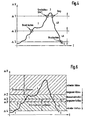
- FIG. 3 is a first embodiment of the braking force distribution control shown during cornering, its effect is illustrated by the timing diagram of Figure 4.
- a second embodiment for the brake force distribution control during a cornering is shown in Figure 5, its effect according to the time diagram Figure 6 is shown.
- FIG. 7 shows a flow chart, which the conventional brake force distribution control during describes a straight-ahead drive.
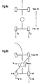
- Figure 8 are the forces and moments acting on the vehicle when and cornering.
- FIG. 1 is a control device for controlling the Brake system of a vehicle shown.
- the control unit 10 comprises an input circuit 12, at least one microcomputer 14 and an output circuit 16. These elements are via a bus system 18 for mutual data exchange connected with each other.
- the input circuit 12 are the Input lines 20, 22, 24 and 26 of wheel speed sensors 28, 30, 32 and 34 fed. You will also receive input lines 36 to 38 supplied by measuring devices 40 to 42. The latter record further operating parameters of the vehicle, the Brake system or the drive unit used to control the Brake system can be evaluated.
- Via output lines 44 to 46 which emanate from the output circuit 16 the control unit 10 via corresponding control devices 48 the wheel brakes 50, 52, 54 and 56.
- the actuators 48 those known from conventional ABS or ABSR systems Include valve devices. Is corresponding in another Embodiment provided a pneumatic brake system, the actuators 48 also here ABS or ABSR systems or electro-pneumatic brake systems known valve devices include.
- the invention Solution is also advantageous in Brake systems with electrical application used. In this Case, the actuators include 48 electric motors, that of the control unit 10 as part of individual wheel Control circuits (current, braking force, braking torque, etc.) are controlled become.
- the control device 10, there the microcomputer 14, comprises Programs that, in addition to conventional functions such as ABS, ASR etc. also the brake force distribution between the front and Regulate the rear axle of the vehicle. This is between driving straight ahead and cornering.
- the curve detection takes place with known from the prior art Procedures.
- cornering can be done by evaluating a steering angle sensor, a lateral acceleration sensor and / or a yaw rate sensor are determined, on the other hand through known measures from the speed difference the vehicle wheels. If straight-ahead driving is recognized, then the regulation of the rear axle known from the art the select-low principle. This means that the Rear axle brake pressure according to the difference between the fastest front wheel and slowest rear wheel becomes.
- the invention Solution implemented as part of programs of the microcomputer 14.
- Figure 2 shows a flow chart showing the basic Structure of the program for regulating the brake force distribution outlined between the front and rear axles.
- the first step 100 checks whether whether the vehicle speed VFZG is a predetermined one Limit value V_EBV (e.g. 3 km / h) has exceeded. exceeds the driving speed the predetermined threshold V_EBV not, the program is terminated and at a predetermined Run through time again.
- Step 100 has shown that the vehicle speed is greater than the minimum control speed V_EBV is in the subsequent step 102 Checks whether a rear wheel is in the ABS control.
- V_EBV Limit value
- Step 104 queries whether both front wheels are in ABS control are located. If this is the case, step 106 Pressure on the rear axle through a given pulse train built up to the pressure on the rear wheels that on the front wheels equalize. After step 106, the program finished and run through again at the specified time. are not both front wheels in the ABS control, are in the Step 108 the necessary to carry out the control Values read in: driving speed VFZG, speed of the right front wheel VVR, speed of the left front wheel VVL, speed of the left rear wheel VHL, Speed of the right rear wheel VHR as well as the information whether there is a cornering.
- Step 110 becomes the fastest front wheel speed VmaxVA as the maximum value selection of the speeds of the right and left front wheel determined.
- Step 112 checks whether the vehicle is cornering located. If this is not the case, the control the rear axle brake pressure when driving straight ahead in FIG. 7 outlined program part initiated. The vehicle is located when cornering, that shown in Figure 3 or 5 Program part initiated. After controlling the Rear axle brake pressure according to the program parts according to the figures 3, 5 or 7 the program is terminated and at a predetermined Run through time again.
- the control of the brake pressure in the rear axle brakes at cornering is part of a first embodiment shown in Figures 3 and 4.
- the rear axle brakes are regulated individually in relation to the front wheels. Exceeds the difference between the speed of one Rear wheel and the fastest front wheel a certain Limit, the pressure in this rear wheel is limited. If a second limit is above the first limit a degradation pulse series occurs. The breakdown pulse series runs until the second limit again is undercut. Pressure builds up after falling below the first limit minus a hysteresis.
- step 200 the differential speed ⁇ VL between the speed of the fastest Front wheel VmaxVA and the speed VHL of the left Rear wheel formed.
- step 202 it is checked whether the differential speed is greater than is a limit value ⁇ 2. If this is not the case, the Step 204 checks whether the EV flag is set. The meaning this flag is described below. is the flag is not set, i.e. the system is in ascending part of the curve of Figure 4 below the Threshold ⁇ 3 (area 1), is continuous according to step 206 pressure built up. This is done in the preferred embodiment a hydraulic brake system in that the inlet valve of the corresponding wheel brake is open. After step 206, the procedure continues in accordance with FIG. 2.
- Step 208 queries whether the differential speed is greater than ⁇ 3, the amount is smaller than ⁇ 2. If the differential speed is less than or equal to ⁇ 3, i.e. has it fallen below this value (area 5 in FIG. 4), is applied according to step 210 for pressure adjustment the brake pressure on the front wheels through pulsed control of the intake valve with a predetermined pulse train Pressure built up and the flag reset in the following step 212. After step 212, the procedure continues in accordance with FIG. 2.
- step 214 If the differential speed is greater than ⁇ 3 (area 4A in Figure 4) according to step 214 by closing the inlet valve the pressure held. After step 214, according to Figure 2 continued.
- Step 202 has shown that the difference exceeds the limit value ⁇ 2 exceeds, the flag is set in step 216. thereupon it is checked in query step 218 whether the difference exceeds a larger limit ⁇ 1.
- Step 220 brake pressure released This is preferably done Embodiment by driving the corresponding exhaust valve with pulses of a given length. After the step 220 is continued according to FIG. 2.
- the procedure described separates each wheel the braking pressures on the rear axle brakes during cornering according to the difference between the speeds of the respective rear wheel and the fastest Front wheel set.
- Threshold values a dynamic regulation in a hatching band used.
- the speed difference is in a given band the wheel pressure kept. Below this volume is built up, above it is dismantled. construction and degradation are dynamic, i.e. the further the controlled variable (Speed difference) in the pressure build-up - or is in the pressure reduction, the faster the corresponding takes place Pressure build-up or reduction.
- FIG. 5 shows a flow diagram which shows a Realization of the second embodiment as a computer program describes.
- the flow chart in FIG. 5 is based on the example shown a right rear wheel. A corresponding one Program part also exists for the left rear wheel.
- the speed difference becomes ⁇ VR between the fastest front wheel VmaxVA and the speed of the right rear wheel VHR calculated.
- the first step of the query 302 it is checked whether the speed difference exceeds the smallest limit ⁇ 4. If this is not the case (area 1 in FIG. 6), then a flag described below is reset in accordance with step 304 and continuously pressurize at step 306 the open inlet valve is built. Then with the program continued according to Figure 2.
- step 308 checks whether it is greater than the limit value ⁇ 3. Is this not the case, i.e. there is the speed difference between the limit values ⁇ 3 and ⁇ 4, in step 310 checks whether the flag is set. If it’s not set, the system is in the area of increasing difference (see area 2 in Figure 6), so that pressure according to step 306 is built.
- Step 312 queries whether the speed difference is greater than the threshold value ⁇ 3 ', which is slightly below of the threshold value ⁇ 3. is if this is not the case (area 6 in FIG. 6), step 314 Pressure built up by pulsed actuation of the inlet valve. The pulse lengths depend on the value of the speed difference. They take with increasing speed difference from. This means that the pressure build-up slows down, the greater the speed difference and the closer the speed difference is fed to the setpoint range becomes. The program according to FIG. 2 is then continued.
- step 312 the speed difference is greater as the threshold value ⁇ 3 '(area 5 in FIG. 6), the Step 316 kept the wheel pressure. Inlet and outlet valve are closed. Then the program follows Figure 2 continued.
- the speed difference also has the limit value ⁇ 3 exceeded (step 308, areas 3 and 4 in FIG. 6), the flag is set in accordance with step 318. It is in Step 320 checks whether the speed difference is the Limit value exceeds ⁇ 2. If not, it is located the speed difference in the specified setpoint range (Area 3 in FIG. 6), then according to step 316 the pressure held. Has the speed difference Threshold value ⁇ 2 is exceeded in the following Step 322 pressure released. This is done in that a Exhaust valve is driven with pulses of a predetermined length. Here too the pulse lengths depend on the value of the speed difference, here with increasing speed difference the pulse lengths become longer. This means that with increasing speed difference the brake pressure release occurs faster while nearby of the setpoint band is carried out more slowly. After that is continued with the program of Figure 2.
- the limit values ⁇ 2 and ⁇ 3 fall in one exemplary embodiment together, so that there is no setpoint band, but a fixed one Setpoint is specified.
- the limit value ⁇ 3 ' forms a hysteresis between increasing and decreasing difference. In one Embodiment is dispensed with this hysteresis, so that the limit value ⁇ 3 'coincides with the value ⁇ 3.
- Step 400 there becomes the slowest rear wheel through a minimum value selection of the speeds of the left and the right rear wheel selected.
- Step 402 becomes the difference ⁇ V between the speed the fastest front wheel VmaxVA and the speed of the slowest rear wheel VminHA and im then step 404 the pressure on both rear wheel brakes controlled depending on the size of the difference ⁇ V. If the value falls below a setpoint range for the Difference or a setpoint pressure built up when exceeded removed, pressure maintained within the setpoint range.
- FIG. 8a shows the straight-ahead drive, at which the speed difference between the slowest rear wheel by brake pressure control in both Rear wheels is adjusted to a target value. This leads to at equal braking forces on both sides.
- FIG. 8b shows the cornering, according to the invention an individual regulation of the rear wheel brakes in relation to the fastest front wheel.
- Due to the resulting larger Braking force FBKA on the wheel on the outside of the curve creates a reversing Moment MBrems, which counteracts the yaw moment MGier.
- the thresholds ⁇ 1 to ⁇ 4 depending on the direction of the curve, the target band (or hysteresis) for the outside wheel, in which the brake pressure is maintained is smaller, than for the inside of the curve. Brake pressure build-up or decrease therefore more sensitive on the outside wheel (construction at larger difference, degradation with smaller difference) than on inside wheel.
- the solution according to the invention was based on the example of a pressure brake system described.
- the appropriate solution will be also in connection with a brake system with electromechanical Tensioning used. Instead of brake pressure Braking force or braking torque by controlling electric motors built, dismantled or held.
- the difference to another Front wheel speed e.g. to an average of the speeds of the front wheels.
Landscapes
- Engineering & Computer Science (AREA)
- Transportation (AREA)
- Mechanical Engineering (AREA)
- Regulating Braking Force (AREA)
- Hydraulic Control Valves For Brake Systems (AREA)
Applications Claiming Priority (3)
| Application Number | Priority Date | Filing Date | Title |
|---|---|---|---|
| DE19651460A DE19651460A1 (de) | 1996-12-11 | 1996-12-11 | Verfahren und Vorrichtung zur Steuerung der Bremskraftverteilung bei einem Fahrzeug |
| DE19651460 | 1996-12-11 | ||
| PCT/DE1997/001940 WO1998025805A1 (de) | 1996-12-11 | 1997-09-04 | Verfahren und vorrichtung zur steuerung der bremskraftverteilung bei einem fahrzeug |
Publications (2)
| Publication Number | Publication Date |
|---|---|
| EP0881974A1 EP0881974A1 (de) | 1998-12-09 |
| EP0881974B1 true EP0881974B1 (de) | 2002-06-19 |
Family
ID=7814348
Family Applications (1)
| Application Number | Title | Priority Date | Filing Date |
|---|---|---|---|
| EP97941866A Expired - Lifetime EP0881974B1 (de) | 1996-12-11 | 1997-09-04 | Verfahren und vorrichtung zur steuerung der bremskraftverteilung bei einem fahrzeug |
Country Status (7)
| Country | Link |
|---|---|
| US (1) | US6322167B1 (ko) |
| EP (1) | EP0881974B1 (ko) |
| JP (1) | JP4233116B2 (ko) |
| KR (1) | KR100514531B1 (ko) |
| CZ (1) | CZ292790B6 (ko) |
| DE (2) | DE19651460A1 (ko) |
| WO (1) | WO1998025805A1 (ko) |
Families Citing this family (19)
| Publication number | Priority date | Publication date | Assignee | Title |
|---|---|---|---|---|
| JP2000095086A (ja) * | 1998-09-22 | 2000-04-04 | Unisia Jecs Corp | ブレーキ制御装置 |
| DE19955094A1 (de) * | 1999-11-16 | 2001-05-23 | Siemens Ag | Verfahren zur Bremsregelung eines Kraftfahrzeugs und Bremsvorrichtung für ein Kraftfahrzeug |
| US6974195B2 (en) | 2000-01-13 | 2005-12-13 | Continental Teves Ag & Co. Ohg | Method for increasing the maneuverability or driving stability of a vehicle during cornering |
| JP2001310721A (ja) * | 2000-04-26 | 2001-11-06 | Fuji Heavy Ind Ltd | 車両の制動力制御装置 |
| DE10022557B4 (de) * | 2000-05-10 | 2012-06-21 | Continental Teves Ag & Co. Ohg | Verfahren zur Bremskraftregelung an einem Kraftfahrzeug |
| FR2818219B1 (fr) * | 2000-12-18 | 2003-02-28 | Delphi Tech Inc | Procede de commande ameliore pour le freinage d'un vehicule automobile en virage et systeme pour sa mise en oeuvre |
| DE10137148A1 (de) * | 2001-07-30 | 2003-02-13 | Knorr Bremse Systeme | Bremsanlage für Nutzfahrzeuganhänger |
| DE10154425A1 (de) * | 2001-11-06 | 2003-05-15 | Continental Teves Ag & Co Ohg | Verfahren zur Bremskraftregelung von Fahrzeugbremsanlagen vom Typ brake-by-wire |
| DE10244557A1 (de) * | 2002-09-25 | 2004-04-08 | Continental Teves Ag & Co. Ohg | Verfahren zur Verbesserung der Fahreigenschaft eines Fahrzeugs |
| JP4374899B2 (ja) * | 2003-05-14 | 2009-12-02 | 日産自動車株式会社 | 車両の制動力制御装置 |
| JP2005047437A (ja) * | 2003-07-30 | 2005-02-24 | Advics:Kk | 車両の運動制御装置 |
| ATE345252T1 (de) * | 2004-07-26 | 2006-12-15 | Delphi Tech Inc | Vorrichtung und verfahren zur bremssteuerung der innen- bzw. aussenräder bei einer kurvenbremsung |
| DE102004040140A1 (de) * | 2004-08-19 | 2006-02-23 | Robert Bosch Gmbh | Verfahren und Vorrichtung zur Behebung einer Umkippgefahr eines Kraftfahrzeugs |
| JP5195871B2 (ja) * | 2010-10-29 | 2013-05-15 | トヨタ自動車株式会社 | 車両用制動力制御装置 |
| JP5196203B2 (ja) * | 2010-11-30 | 2013-05-15 | トヨタ自動車株式会社 | 車両用制動力制御装置 |
| JP5962906B2 (ja) * | 2012-06-22 | 2016-08-03 | 株式会社アドヴィックス | 車両の制動力制御装置 |
| DE102014215306A1 (de) | 2014-08-04 | 2016-02-04 | Robert Bosch Gmbh | Verfahren und Vorrichtung zum Betreiben eines Fahrzeugs |
| FR3054987A1 (fr) * | 2016-08-09 | 2018-02-16 | Peugeot Citroen Automobiles Sa | Dispositif de controle des pressions des liquides de frein pour les deux roues d'un train arriere de vehicule automobile |
| DE102021209920A1 (de) | 2021-09-08 | 2023-03-09 | Robert Bosch Gesellschaft mit beschränkter Haftung | Verfahren zum Abbremsen eines Kraftfahrzeugs |
Family Cites Families (12)
| Publication number | Priority date | Publication date | Assignee | Title |
|---|---|---|---|---|
| US4494801A (en) * | 1982-03-08 | 1985-01-22 | Honda Giken Kogyo Kabushiki Kaisha | Antilock brake system with separate front- and rear-wheel safety means |
| DE3301948A1 (de) * | 1983-01-21 | 1984-07-26 | Alfred Teves Gmbh, 6000 Frankfurt | Verfahren und vorrichtung zur steuerung der bremskraftverteilung |
| DE3306611A1 (de) * | 1983-02-25 | 1984-08-30 | Alfred Teves Gmbh, 6000 Frankfurt | Verfahren und vorrichtung zur steuerung der bremskraftverteilung |
| JPS6141657A (ja) * | 1984-07-31 | 1986-02-28 | Nippon Ee B S Kk | アンチスキッド装置用液圧制御装置 |
| DE3829951A1 (de) * | 1988-09-03 | 1990-03-15 | Daimler Benz Ag | Verfahren zur lastabhaengigen regelung des bremsdruckes an fahrzeugen und vorrichtung zur durchfuehrung des verfahrens |
| JP2679416B2 (ja) * | 1990-12-21 | 1997-11-19 | 日産自動車株式会社 | 車両の制動力前後配分制御装置 |
| DE4112388A1 (de) * | 1991-04-16 | 1992-10-22 | Bosch Gmbh Robert | Bremsdruckregelanlage fuer ein fahrzeug |
| DE4200046C2 (de) * | 1992-01-03 | 1995-08-24 | Daimler Benz Ag | Bremsanlage mit einstellbar veränderbarer Vorderachs-/Hinterachs-Bremskraftverteilung |
| JP3496266B2 (ja) * | 1994-03-15 | 2004-02-09 | トヨタ自動車株式会社 | ブレーキシステム |
| US5803678A (en) * | 1995-06-20 | 1998-09-08 | American Saw & Mfg. Company | Hole cutting tools |
| DE19522632A1 (de) * | 1995-06-22 | 1997-01-02 | Teves Gmbh Alfred | Verfahren zur Verbesserung des Regelverhaltens eines Blockierschutzregelungssystems |
| JP3116787B2 (ja) * | 1995-10-06 | 2000-12-11 | トヨタ自動車株式会社 | 車輌の挙動制御装置 |
-
1996
- 1996-12-11 DE DE19651460A patent/DE19651460A1/de not_active Withdrawn
-
1997
- 1997-09-04 WO PCT/DE1997/001940 patent/WO1998025805A1/de active IP Right Grant
- 1997-09-04 US US09/117,759 patent/US6322167B1/en not_active Expired - Lifetime
- 1997-09-04 DE DE59707560T patent/DE59707560D1/de not_active Expired - Lifetime
- 1997-09-04 JP JP52606598A patent/JP4233116B2/ja not_active Expired - Lifetime
- 1997-09-04 EP EP97941866A patent/EP0881974B1/de not_active Expired - Lifetime
- 1997-09-04 CZ CZ19981703A patent/CZ292790B6/cs not_active IP Right Cessation
- 1997-09-04 KR KR1019980705562A patent/KR100514531B1/ko not_active IP Right Cessation
Also Published As
| Publication number | Publication date |
|---|---|
| WO1998025805A1 (de) | 1998-06-18 |
| JP2000505760A (ja) | 2000-05-16 |
| KR100514531B1 (ko) | 2006-03-20 |
| JP4233116B2 (ja) | 2009-03-04 |
| EP0881974A1 (de) | 1998-12-09 |
| DE59707560D1 (de) | 2002-07-25 |
| CZ292790B6 (cs) | 2003-12-17 |
| US6322167B1 (en) | 2001-11-27 |
| KR19990081851A (ko) | 1999-11-15 |
| DE19651460A1 (de) | 1998-06-18 |
| CZ170398A3 (cs) | 1999-01-13 |
Similar Documents
| Publication | Publication Date | Title |
|---|---|---|
| EP0881974B1 (de) | Verfahren und vorrichtung zur steuerung der bremskraftverteilung bei einem fahrzeug | |
| DE60311566T2 (de) | Fahrzeugbremssystem und Verfahren zu dessen Regelung | |
| EP1016572B1 (de) | Vorrichtung und Verfahren zur Stabilisierung eines aus einem Zugfahrzeug und einem Anhänger bzw. Auflieger bestehenden Fahrzeuggespannes | |
| WO2002100696A1 (de) | Verfahren zur regelung der fahrstabilität | |
| DE19616732B4 (de) | Verfahren und Vorrichtung zur Steuerung der Bremsanlage eines Fahrzeugs | |
| EP0844155B1 (de) | Verfahren zur Giermoment-Abschwächung in einem Fahrzeug mit Antiblockiersystem | |
| DE19545001B4 (de) | Verfahren zur Giermoment-Abschwächung bei einem Antiblockiersystem | |
| DE4433459C2 (de) | Antriebsschlupfregelsystem | |
| EP1131235B1 (de) | Verfahren und vorrichtung zur stabilisierung eines mit einer schlupfgeregelten bremsanlage ausgestatteten fahrzeugs | |
| EP1545950B1 (de) | Verfahren zur verbesserung der fahreigenschaft eines fahrzeugs bei teilgebremster fahrt | |
| EP1156952B1 (de) | Vorrichtung und verfahren zur regelung des radschlupfes nach einer schleudererkennung | |
| EP0780275A2 (de) | Verfahren und Vorrichtung zur Antriebsschlupfregelung | |
| DE19713252A1 (de) | Verfahren und Vorrichtung zur Ermittlung einer die Fahrzeuggeschwindigkeit beschreibenden Größe | |
| DE10234606A1 (de) | Verfahren und Vorrichtung zur Stabilisierung eines Fahrzeugs | |
| EP1070623B1 (de) | Verfahren zur Antriebsschlupfregelung | |
| DE102010039823A1 (de) | Verfahren und Vorrichtung zur Antriebsschlupfregelung eines Einspurfahrzeugs | |
| DE10203422A1 (de) | Verfahren zur Traktionsregelung schlupfbehafteter Räder wenigstens einer Antriebsachse | |
| DE19542295B4 (de) | Bremssystem für ein Fahrzeug | |
| DE19919969B4 (de) | Antriebsschlupfregelverfahren | |
| DE19933085A1 (de) | Verfahren und Vorrichtung zur Antriebsschlupfregelung | |
| EP1514755B1 (de) | Verfahren zur Steuerung des Eingangsdrucks eines ABS-Regelventils | |
| DE102006038512A1 (de) | Vorrichtung zum Verkürzen des Bremsweges eines Fahrzeugs | |
| DE10127828A1 (de) | Verfahren und Vorrichtung zur Einstellung der Bremswirkung bei einem Fahrzeug | |
| EP0980781B1 (de) | Verfahren und Vorrichtung zur Antriebsschlupfregelung bei Kraftfahrzeugen | |
| DE69933685T2 (de) | Verfahren und Vorrichtung zur Kraftfahrzeug -Antischlupfregelung |
Legal Events
| Date | Code | Title | Description |
|---|---|---|---|
| PUAI | Public reference made under article 153(3) epc to a published international application that has entered the european phase |
Free format text: ORIGINAL CODE: 0009012 |
|
| AK | Designated contracting states |
Kind code of ref document: A1 Designated state(s): DE FR GB IT |
|
| 17P | Request for examination filed |
Effective date: 19981218 |
|
| 17Q | First examination report despatched |
Effective date: 20010412 |
|
| GRAG | Despatch of communication of intention to grant |
Free format text: ORIGINAL CODE: EPIDOS AGRA |
|
| GRAG | Despatch of communication of intention to grant |
Free format text: ORIGINAL CODE: EPIDOS AGRA |
|
| GRAH | Despatch of communication of intention to grant a patent |
Free format text: ORIGINAL CODE: EPIDOS IGRA |
|
| GRAH | Despatch of communication of intention to grant a patent |
Free format text: ORIGINAL CODE: EPIDOS IGRA |
|
| GRAA | (expected) grant |
Free format text: ORIGINAL CODE: 0009210 |
|
| AK | Designated contracting states |
Kind code of ref document: B1 Designated state(s): DE FR GB IT |
|
| REG | Reference to a national code |
Ref country code: GB Ref legal event code: FG4D Free format text: NOT ENGLISH |
|
| REF | Corresponds to: |
Ref document number: 59707560 Country of ref document: DE Date of ref document: 20020725 |
|
| PGFP | Annual fee paid to national office [announced via postgrant information from national office to epo] |
Ref country code: GB Payment date: 20020814 Year of fee payment: 6 |
|
| GBT | Gb: translation of ep patent filed (gb section 77(6)(a)/1977) |
Effective date: 20020917 |
|
| ET | Fr: translation filed | ||
| PLBE | No opposition filed within time limit |
Free format text: ORIGINAL CODE: 0009261 |
|
| STAA | Information on the status of an ep patent application or granted ep patent |
Free format text: STATUS: NO OPPOSITION FILED WITHIN TIME LIMIT |
|
| 26N | No opposition filed |
Effective date: 20030320 |
|
| PG25 | Lapsed in a contracting state [announced via postgrant information from national office to epo] |
Ref country code: GB Free format text: LAPSE BECAUSE OF NON-PAYMENT OF DUE FEES Effective date: 20030904 |
|
| GBPC | Gb: european patent ceased through non-payment of renewal fee | ||
| REG | Reference to a national code |
Ref country code: FR Ref legal event code: PLFP Year of fee payment: 20 |
|
| PGFP | Annual fee paid to national office [announced via postgrant information from national office to epo] |
Ref country code: FR Payment date: 20160922 Year of fee payment: 20 |
|
| PGFP | Annual fee paid to national office [announced via postgrant information from national office to epo] |
Ref country code: DE Payment date: 20161125 Year of fee payment: 20 |
|
| PGFP | Annual fee paid to national office [announced via postgrant information from national office to epo] |
Ref country code: IT Payment date: 20160922 Year of fee payment: 20 |
|
| REG | Reference to a national code |
Ref country code: DE Ref legal event code: R071 Ref document number: 59707560 Country of ref document: DE |