EP0881974B1 - Process and device for controlling the braking force distribution in a vehicle - Google Patents
Process and device for controlling the braking force distribution in a vehicle Download PDFInfo
- Publication number
- EP0881974B1 EP0881974B1 EP97941866A EP97941866A EP0881974B1 EP 0881974 B1 EP0881974 B1 EP 0881974B1 EP 97941866 A EP97941866 A EP 97941866A EP 97941866 A EP97941866 A EP 97941866A EP 0881974 B1 EP0881974 B1 EP 0881974B1
- Authority
- EP
- European Patent Office
- Prior art keywords
- speed
- wheel
- braking force
- difference
- speed difference
- Prior art date
- Legal status (The legal status is an assumption and is not a legal conclusion. Google has not performed a legal analysis and makes no representation as to the accuracy of the status listed.)
- Expired - Lifetime
Links
Images


Classifications
-
- B—PERFORMING OPERATIONS; TRANSPORTING
- B60—VEHICLES IN GENERAL
- B60T—VEHICLE BRAKE CONTROL SYSTEMS OR PARTS THEREOF; BRAKE CONTROL SYSTEMS OR PARTS THEREOF, IN GENERAL; ARRANGEMENT OF BRAKING ELEMENTS ON VEHICLES IN GENERAL; PORTABLE DEVICES FOR PREVENTING UNWANTED MOVEMENT OF VEHICLES; VEHICLE MODIFICATIONS TO FACILITATE COOLING OF BRAKES
- B60T8/00—Arrangements for adjusting wheel-braking force to meet varying vehicular or ground-surface conditions, e.g. limiting or varying distribution of braking force
- B60T8/17—Using electrical or electronic regulation means to control braking
- B60T8/176—Brake regulation specially adapted to prevent excessive wheel slip during vehicle deceleration, e.g. ABS
- B60T8/1766—Proportioning of brake forces according to vehicle axle loads, e.g. front to rear of vehicle
-
- B—PERFORMING OPERATIONS; TRANSPORTING
- B60—VEHICLES IN GENERAL
- B60T—VEHICLE BRAKE CONTROL SYSTEMS OR PARTS THEREOF; BRAKE CONTROL SYSTEMS OR PARTS THEREOF, IN GENERAL; ARRANGEMENT OF BRAKING ELEMENTS ON VEHICLES IN GENERAL; PORTABLE DEVICES FOR PREVENTING UNWANTED MOVEMENT OF VEHICLES; VEHICLE MODIFICATIONS TO FACILITATE COOLING OF BRAKES
- B60T8/00—Arrangements for adjusting wheel-braking force to meet varying vehicular or ground-surface conditions, e.g. limiting or varying distribution of braking force
- B60T8/17—Using electrical or electronic regulation means to control braking
- B60T8/176—Brake regulation specially adapted to prevent excessive wheel slip during vehicle deceleration, e.g. ABS
- B60T8/1764—Regulation during travel on surface with different coefficients of friction, e.g. between left and right sides, mu-split or between front and rear
-
- B—PERFORMING OPERATIONS; TRANSPORTING
- B60—VEHICLES IN GENERAL
- B60T—VEHICLE BRAKE CONTROL SYSTEMS OR PARTS THEREOF; BRAKE CONTROL SYSTEMS OR PARTS THEREOF, IN GENERAL; ARRANGEMENT OF BRAKING ELEMENTS ON VEHICLES IN GENERAL; PORTABLE DEVICES FOR PREVENTING UNWANTED MOVEMENT OF VEHICLES; VEHICLE MODIFICATIONS TO FACILITATE COOLING OF BRAKES
- B60T2201/00—Particular use of vehicle brake systems; Special systems using also the brakes; Special software modules within the brake system controller
- B60T2201/16—Curve braking control, e.g. turn control within ABS control algorithm
Definitions
- the invention relates to a method and a device to control the braking force distribution in a vehicle according to the preambles of the independent claims.
- Such a method or device is for example from EP-B1 509 237 (US Pat. No. 5,281,012) known.
- EP-B1 509 237 US Pat. No. 5,281,012
- the speed difference between the fastest front wheel and the slowest rear wheel is essentially a predetermined one Takes value.
- the rear axle brake pressure can because of the increasing speed difference be reduced to zero. Therefore at the known solution provided the rear axle brake pressure limit to a minimum value dependent on the curve radius and the predetermined value for the speed difference to adapt to the vehicle speed.
- the solution according to the invention improves an electronic one Brake force distribution control for corner braking.
- the brake force distribution control according to the invention also in the area of critical driving dynamics at high cornering speeds (greater than 60 to 120 km / h) is maintained.
- the solution according to the invention is advantageous very adaptable to different vehicles (Sports cars, limousines, vans, etc.) because after the Brake force distribution diagram (adaptive behavior) regulated becomes.
- the individual regulation of Rear axle only compared to the known select-low control shifted half the print volume. This does one for the Driver noticeably increased comfort in the pressure build-up over the entire speed range.
- ABS systems (4-channel) is necessary.
- the inventive method is particularly advantageous Solution not only for hydraulic brake systems, but also also with pneumatic, with electrically controlled hydraulic and pneumatic brake systems as well as brake systems applied with electromotive clamping.
- FIG. 1 is an overview block diagram of a control device to control the wheel brakes.
- FIG. 2 shows a flow chart, which is a realization example of an electronic Brake force distribution control according to the invention Procedure outlined as a computer program.
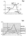
- FIG. 3 is a first embodiment of the braking force distribution control shown during cornering, its effect is illustrated by the timing diagram of Figure 4.
- a second embodiment for the brake force distribution control during a cornering is shown in Figure 5, its effect according to the time diagram Figure 6 is shown.
- FIG. 7 shows a flow chart, which the conventional brake force distribution control during describes a straight-ahead drive.
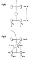
- Figure 8 are the forces and moments acting on the vehicle when and cornering.
- FIG. 1 is a control device for controlling the Brake system of a vehicle shown.
- the control unit 10 comprises an input circuit 12, at least one microcomputer 14 and an output circuit 16. These elements are via a bus system 18 for mutual data exchange connected with each other.
- the input circuit 12 are the Input lines 20, 22, 24 and 26 of wheel speed sensors 28, 30, 32 and 34 fed. You will also receive input lines 36 to 38 supplied by measuring devices 40 to 42. The latter record further operating parameters of the vehicle, the Brake system or the drive unit used to control the Brake system can be evaluated.
- Via output lines 44 to 46 which emanate from the output circuit 16 the control unit 10 via corresponding control devices 48 the wheel brakes 50, 52, 54 and 56.
- the actuators 48 those known from conventional ABS or ABSR systems Include valve devices. Is corresponding in another Embodiment provided a pneumatic brake system, the actuators 48 also here ABS or ABSR systems or electro-pneumatic brake systems known valve devices include.
- the invention Solution is also advantageous in Brake systems with electrical application used. In this Case, the actuators include 48 electric motors, that of the control unit 10 as part of individual wheel Control circuits (current, braking force, braking torque, etc.) are controlled become.
- the control device 10, there the microcomputer 14, comprises Programs that, in addition to conventional functions such as ABS, ASR etc. also the brake force distribution between the front and Regulate the rear axle of the vehicle. This is between driving straight ahead and cornering.
- the curve detection takes place with known from the prior art Procedures.
- cornering can be done by evaluating a steering angle sensor, a lateral acceleration sensor and / or a yaw rate sensor are determined, on the other hand through known measures from the speed difference the vehicle wheels. If straight-ahead driving is recognized, then the regulation of the rear axle known from the art the select-low principle. This means that the Rear axle brake pressure according to the difference between the fastest front wheel and slowest rear wheel becomes.
- the invention Solution implemented as part of programs of the microcomputer 14.
- Figure 2 shows a flow chart showing the basic Structure of the program for regulating the brake force distribution outlined between the front and rear axles.
- the first step 100 checks whether whether the vehicle speed VFZG is a predetermined one Limit value V_EBV (e.g. 3 km / h) has exceeded. exceeds the driving speed the predetermined threshold V_EBV not, the program is terminated and at a predetermined Run through time again.
- Step 100 has shown that the vehicle speed is greater than the minimum control speed V_EBV is in the subsequent step 102 Checks whether a rear wheel is in the ABS control.
- V_EBV Limit value
- Step 104 queries whether both front wheels are in ABS control are located. If this is the case, step 106 Pressure on the rear axle through a given pulse train built up to the pressure on the rear wheels that on the front wheels equalize. After step 106, the program finished and run through again at the specified time. are not both front wheels in the ABS control, are in the Step 108 the necessary to carry out the control Values read in: driving speed VFZG, speed of the right front wheel VVR, speed of the left front wheel VVL, speed of the left rear wheel VHL, Speed of the right rear wheel VHR as well as the information whether there is a cornering.
- Step 110 becomes the fastest front wheel speed VmaxVA as the maximum value selection of the speeds of the right and left front wheel determined.
- Step 112 checks whether the vehicle is cornering located. If this is not the case, the control the rear axle brake pressure when driving straight ahead in FIG. 7 outlined program part initiated. The vehicle is located when cornering, that shown in Figure 3 or 5 Program part initiated. After controlling the Rear axle brake pressure according to the program parts according to the figures 3, 5 or 7 the program is terminated and at a predetermined Run through time again.
- the control of the brake pressure in the rear axle brakes at cornering is part of a first embodiment shown in Figures 3 and 4.
- the rear axle brakes are regulated individually in relation to the front wheels. Exceeds the difference between the speed of one Rear wheel and the fastest front wheel a certain Limit, the pressure in this rear wheel is limited. If a second limit is above the first limit a degradation pulse series occurs. The breakdown pulse series runs until the second limit again is undercut. Pressure builds up after falling below the first limit minus a hysteresis.
- step 200 the differential speed ⁇ VL between the speed of the fastest Front wheel VmaxVA and the speed VHL of the left Rear wheel formed.
- step 202 it is checked whether the differential speed is greater than is a limit value ⁇ 2. If this is not the case, the Step 204 checks whether the EV flag is set. The meaning this flag is described below. is the flag is not set, i.e. the system is in ascending part of the curve of Figure 4 below the Threshold ⁇ 3 (area 1), is continuous according to step 206 pressure built up. This is done in the preferred embodiment a hydraulic brake system in that the inlet valve of the corresponding wheel brake is open. After step 206, the procedure continues in accordance with FIG. 2.
- Step 208 queries whether the differential speed is greater than ⁇ 3, the amount is smaller than ⁇ 2. If the differential speed is less than or equal to ⁇ 3, i.e. has it fallen below this value (area 5 in FIG. 4), is applied according to step 210 for pressure adjustment the brake pressure on the front wheels through pulsed control of the intake valve with a predetermined pulse train Pressure built up and the flag reset in the following step 212. After step 212, the procedure continues in accordance with FIG. 2.
- step 214 If the differential speed is greater than ⁇ 3 (area 4A in Figure 4) according to step 214 by closing the inlet valve the pressure held. After step 214, according to Figure 2 continued.
- Step 202 has shown that the difference exceeds the limit value ⁇ 2 exceeds, the flag is set in step 216. thereupon it is checked in query step 218 whether the difference exceeds a larger limit ⁇ 1.
- Step 220 brake pressure released This is preferably done Embodiment by driving the corresponding exhaust valve with pulses of a given length. After the step 220 is continued according to FIG. 2.
- the procedure described separates each wheel the braking pressures on the rear axle brakes during cornering according to the difference between the speeds of the respective rear wheel and the fastest Front wheel set.
- Threshold values a dynamic regulation in a hatching band used.
- the speed difference is in a given band the wheel pressure kept. Below this volume is built up, above it is dismantled. construction and degradation are dynamic, i.e. the further the controlled variable (Speed difference) in the pressure build-up - or is in the pressure reduction, the faster the corresponding takes place Pressure build-up or reduction.
- FIG. 5 shows a flow diagram which shows a Realization of the second embodiment as a computer program describes.
- the flow chart in FIG. 5 is based on the example shown a right rear wheel. A corresponding one Program part also exists for the left rear wheel.
- the speed difference becomes ⁇ VR between the fastest front wheel VmaxVA and the speed of the right rear wheel VHR calculated.
- the first step of the query 302 it is checked whether the speed difference exceeds the smallest limit ⁇ 4. If this is not the case (area 1 in FIG. 6), then a flag described below is reset in accordance with step 304 and continuously pressurize at step 306 the open inlet valve is built. Then with the program continued according to Figure 2.
- step 308 checks whether it is greater than the limit value ⁇ 3. Is this not the case, i.e. there is the speed difference between the limit values ⁇ 3 and ⁇ 4, in step 310 checks whether the flag is set. If it’s not set, the system is in the area of increasing difference (see area 2 in Figure 6), so that pressure according to step 306 is built.
- Step 312 queries whether the speed difference is greater than the threshold value ⁇ 3 ', which is slightly below of the threshold value ⁇ 3. is if this is not the case (area 6 in FIG. 6), step 314 Pressure built up by pulsed actuation of the inlet valve. The pulse lengths depend on the value of the speed difference. They take with increasing speed difference from. This means that the pressure build-up slows down, the greater the speed difference and the closer the speed difference is fed to the setpoint range becomes. The program according to FIG. 2 is then continued.
- step 312 the speed difference is greater as the threshold value ⁇ 3 '(area 5 in FIG. 6), the Step 316 kept the wheel pressure. Inlet and outlet valve are closed. Then the program follows Figure 2 continued.
- the speed difference also has the limit value ⁇ 3 exceeded (step 308, areas 3 and 4 in FIG. 6), the flag is set in accordance with step 318. It is in Step 320 checks whether the speed difference is the Limit value exceeds ⁇ 2. If not, it is located the speed difference in the specified setpoint range (Area 3 in FIG. 6), then according to step 316 the pressure held. Has the speed difference Threshold value ⁇ 2 is exceeded in the following Step 322 pressure released. This is done in that a Exhaust valve is driven with pulses of a predetermined length. Here too the pulse lengths depend on the value of the speed difference, here with increasing speed difference the pulse lengths become longer. This means that with increasing speed difference the brake pressure release occurs faster while nearby of the setpoint band is carried out more slowly. After that is continued with the program of Figure 2.
- the limit values ⁇ 2 and ⁇ 3 fall in one exemplary embodiment together, so that there is no setpoint band, but a fixed one Setpoint is specified.
- the limit value ⁇ 3 ' forms a hysteresis between increasing and decreasing difference. In one Embodiment is dispensed with this hysteresis, so that the limit value ⁇ 3 'coincides with the value ⁇ 3.
- Step 400 there becomes the slowest rear wheel through a minimum value selection of the speeds of the left and the right rear wheel selected.
- Step 402 becomes the difference ⁇ V between the speed the fastest front wheel VmaxVA and the speed of the slowest rear wheel VminHA and im then step 404 the pressure on both rear wheel brakes controlled depending on the size of the difference ⁇ V. If the value falls below a setpoint range for the Difference or a setpoint pressure built up when exceeded removed, pressure maintained within the setpoint range.
- FIG. 8a shows the straight-ahead drive, at which the speed difference between the slowest rear wheel by brake pressure control in both Rear wheels is adjusted to a target value. This leads to at equal braking forces on both sides.
- FIG. 8b shows the cornering, according to the invention an individual regulation of the rear wheel brakes in relation to the fastest front wheel.
- Due to the resulting larger Braking force FBKA on the wheel on the outside of the curve creates a reversing Moment MBrems, which counteracts the yaw moment MGier.
- the thresholds ⁇ 1 to ⁇ 4 depending on the direction of the curve, the target band (or hysteresis) for the outside wheel, in which the brake pressure is maintained is smaller, than for the inside of the curve. Brake pressure build-up or decrease therefore more sensitive on the outside wheel (construction at larger difference, degradation with smaller difference) than on inside wheel.
- the solution according to the invention was based on the example of a pressure brake system described.
- the appropriate solution will be also in connection with a brake system with electromechanical Tensioning used. Instead of brake pressure Braking force or braking torque by controlling electric motors built, dismantled or held.
- the difference to another Front wheel speed e.g. to an average of the speeds of the front wheels.
Abstract
Description
Die Erfindung betrifft ein Verfahren und eine Vorrichtung zur Steuerung der Bremskraftverteilung bei einem Fahrzeug gemäß den Oberbegriffen der unabhängigen Patentansprüche.The invention relates to a method and a device to control the braking force distribution in a vehicle according to the preambles of the independent claims.
Ein derartiges Verfahren bzw. eine derartige Vorrichtung ist beispielsweise aus der EP-B1 509 237 (US-Patent 5 281 012) bekannt. Dort wird die Differenz zwischen dem schnellsten Vorderrad und dem langsamsten Hinterrad gebildet und der Bremsdruck an den Hinterrädern derart eingestellt, daß die Geschwindigkeitsdifferenz zwischen dem schnellsten Vorderrad und dem langsamsten Hinterrad im wesentlichen einen vorgegebenen Wert einnimmt. Bei Bremsungen in Kurven kann der Hinterachsbremsdruck wegen der größer werdenden Geschwindigkeitsdifferenz bis auf Null reduziert werden. Daher ist bei der bekannten Lösung vorgesehen, den Hinterachsbremsdruck auf einen vom Kurvenradius abhängigen Minimalwert zu begrenzen und den vorgegebenen Wert für die Geschwindigkeitsdifferenz an die Fahrzeuggeschwindigkeit anzupassen. Such a method or device is for example from EP-B1 509 237 (US Pat. No. 5,281,012) known. There is the difference between the fastest Front wheel and the slowest rear wheel formed and the Brake pressure set on the rear wheels so that the Speed difference between the fastest front wheel and the slowest rear wheel is essentially a predetermined one Takes value. When braking in curves, the rear axle brake pressure can because of the increasing speed difference be reduced to zero. Therefore at the known solution provided the rear axle brake pressure limit to a minimum value dependent on the curve radius and the predetermined value for the speed difference to adapt to the vehicle speed.
Obwohl diese Lösung die Problematik der Kurvenbremsung zufriedenstellend löst, hat es sich gezeigt, daß sie in einigen Fällen, insbesondere bei hohen Kurvengeschwindigkeiten Einschränkungen im Fahrverhalten aufweist, da kein zum Fahrzeuggiermoment gegendrehendes Bremsmoment erzeugt wird.Although this solution satisfies the problem of corner braking solves, it has been shown that in some Cases, especially at high cornering speeds Has restrictions in driving behavior, since none to the vehicle yaw moment counter-rotating braking torque is generated.
Es ist daher Aufgabe der Erfindung, eine elektronische Bremskraftverteilungsregelung bei Kurvenbremsungen zu verbessern.It is therefore an object of the invention to provide an electronic Improve braking force distribution control when cornering.
Dies wird durch die kennzeichnenden Merkmale der unabhängigen Patentansprüche erreicht.This is due to the distinctive features of the independent Claims reached.
Die erfindungsgemäße Lösung verbessert eine elektronische Bremskraftverteilungsregelung bei Kurvenbremsungen.The solution according to the invention improves an electronic one Brake force distribution control for corner braking.
Besonders vorteilhaft ist, daß im Teilbremsgebiet die Neigung zum Übersteuern bei Bremsungen nahe an der Kurvengrenzgeschwindigkeit außerhalb des ABS-Regelbereichs durch das durch die erfindungsgemäße Lösung dem Giermoment entgegengerichtete Bremsmoment abnimmt.It is particularly advantageous that the slope in the partial braking area for oversteering when braking close to the cornering limit speed outside the ABS control range by the directed against the yaw moment by the solution according to the invention Braking torque decreases.
Vorteilhaft ist ferner, daß die erfindungsgemäße Bremskraftverteilungsregelung auch im fahrdynamisch kritischen Bereich bei hohen Kurvengeschwindigkeiten (größer als 60 bis 120 km/h) aufrechterhalten wird.It is also advantageous that the brake force distribution control according to the invention also in the area of critical driving dynamics at high cornering speeds (greater than 60 to 120 km / h) is maintained.
Vorteilhaft ist ferner, daß das durch die Bremsensteuerung erzeugte gegendrehende Moment nicht ruckartig aufgebaut wird, sondern mit Anwachsen des vom Fahrer vorgegebenen Bremsdrucks zur Verfügung steht. Das Fahrzeug wird bei erheblichen Vorteilen im Komfort dennoch ausreichend stabilisiert. It is also advantageous that the brake control generated counter-rotating moment not jerky but with the growth of what the driver specified Brake pressure is available. The vehicle gets substantial Advantages in comfort are nevertheless sufficiently stabilized.
Ferner ist in vorteilhafter Weise die erfindungsgemäße Lösung sehr anpassungsfähig an unterschiedliche Fahrzeuge (Sportwagen, Limousinen, Transporter, etc.), da nach dem Bremskraftverteilungsdiagramm (adaptives Verhalten) geregelt wird.Furthermore, the solution according to the invention is advantageous very adaptable to different vehicles (Sports cars, limousines, vans, etc.) because after the Brake force distribution diagram (adaptive behavior) regulated becomes.
In vorteilhafter Weise wird durch die Individualregelung der Hinterachse gegenüber der bekannten Select-Low-Regelung nur das halbe Druckvolumen verschoben. Dies bewirkt eine für den Fahrer deutlich spürbare Komforterhöhung bei den Druckaufbauten über den gesamten Geschwindigkeitsbereich.Advantageously, the individual regulation of Rear axle only compared to the known select-low control shifted half the print volume. This does one for the Driver noticeably increased comfort in the pressure build-up over the entire speed range.
Ferner ist vorteilhaft, daß keine zusätzliche Hardware zu den bekannten ABS-Systemen (4-Kanal) notwendig ist.It is also advantageous that no additional hardware is required the known ABS systems (4-channel) is necessary.
In besonders vorteilhafter Weise wird die erfindungsgemäße Lösung nicht nur bei hydraulischen Bremsanlagen, sondern auch bei pneumatischen, bei elektrisch gesteuerten hydraulischen und pneumatischen Bremsanlagen sowie bei Bremsanlagen mit elektromotorischer Zuspannung angewendet.The inventive method is particularly advantageous Solution not only for hydraulic brake systems, but also also with pneumatic, with electrically controlled hydraulic and pneumatic brake systems as well as brake systems applied with electromotive clamping.
Weitere Vorteile ergeben sich aus der nachfolgenden Beschreibung von Ausführungsbeispielen bzw. aus den abhängigen Patentansprüchen.Further advantages result from the description below from exemplary embodiments or from the dependent ones Claims.
Die Erfindung wird nachstehend anhand der in der Zeichnung dargestellten Ausführungsformen näher erläutert. Dabei zeigt Figur 1 ein Übersichtsblockschaltbild einer Steuereinrichtung zur Steuerung der Radbremsen. Figur 2 zeigt ein Flußdiagramm, welches ein Realisierungsbeispiel einer elektronischen Bremskraftverteilungsregelung gemäß der erfindungsgemäßen Vorgehensweise als Rechnerprogramm skizziert. In Figur 3 ist ein erstes Ausführungsbeispiel der Bremskraftverteilungsregelung während Kurvenfahrt dargestellt, dessen Wirkung anhand des Zeitdiagramms nach Figur 4 verdeutlicht ist. Ein zweites Ausführungsbeispiel für die Bremskraftverteilungsregelung während einer Kurvenfahrt ist in Figur 5 dargestellt, dessen Wirkung entsprechend im Zeitdiagramm nach Figur 6 dargestellt ist. Figur 7 zeigt ein Flußdiagramm, welches die herkömmliche Bremskraftverteilungsregelung während einer Geradeausfahrt beschreibt. In Figur 8 schließlich sind die am Fahrzeug angreifenden Kräfte und Momente bei Geradeaus- und Kurvenfahrt dargestellt.The invention is described below with reference to the drawing illustrated embodiments explained in more detail. It shows Figure 1 is an overview block diagram of a control device to control the wheel brakes. FIG. 2 shows a flow chart, which is a realization example of an electronic Brake force distribution control according to the invention Procedure outlined as a computer program. In figure 3 is a first embodiment of the braking force distribution control shown during cornering, its effect is illustrated by the timing diagram of Figure 4. A second embodiment for the brake force distribution control during a cornering is shown in Figure 5, its effect according to the time diagram Figure 6 is shown. FIG. 7 shows a flow chart, which the conventional brake force distribution control during describes a straight-ahead drive. Finally in Figure 8 are the forces and moments acting on the vehicle when and cornering.
In Figur 1 ist eine Steuereinrichtung zur Steuerung der
Bremsanlage eines Fahrzeugs dargestellt. Die Steuereinheit
10 umfaßt eine Eingangsschaltung 12, wenigstens einen Mikrocomputer
14 und eine Ausgangsschaltung 16. Diese Elemente
sind über ein Bussystem 18 zum gegenseitigen Datenaustausch
miteinander verbunden. Der Eingangsschaltung 12 werden die
Eingangsleitungen 20, 22, 24 und 26 von Raddrehzahlsensoren
28, 30, 32 und 34 zugeführt. Ferner werden ihr Eingangsleitungen
36 bis 38 von Meßeinrichtungen 40 bis 42 zugeführt.
Letztere erfassen weitere Betriebsgrößen des Fahrzeugs, der
Bremsanlage oder der Antriebseinheit, die zur Steuerung der
Bremsanlage ausgewertet werden. Über Ausgangsleitungen 44
bis 46, die von der Ausgangsschaltung 16 ausgehen, beeinflußt
die Steuereinheit 10 über entsprechende Stelleinrichtungen
48 die Radbremsen 50, 52, 54 und 56. Im bevorzugten
Ausführungsbeispiel handelt es sich bei der Bremsanlage um
eine hydraulische Bremsanlage, wobei die Stelleinrichtungen
48 die aus herkömmlichen ABS- oder ABSR-Systemen bekannten
Ventileinrichtungen umfassen. Entsprechend ist in einem anderen
Ausführungsbeispiel eine pneumatische Bremsanlage vorgesehen,
wobei die Stelleinrichtungen 48 auch hier die aus
ABS- bzw. ABSR-Systemen oder elektro-pneumatischen Bremsanlagen
bekannten Ventileinrichtungen umfassen. Die erfindungsgemäße
Lösung wird in vorteilhafter Weise auch bei
Bremsanlagen mit elektrischer Zuspannung eingesetzt. In diesem
Fall umfassen die Stelleinrichtungen 48 Elektromotoren,
die von der Steuereinheit 10 im Rahmen von radindividuellen
Regelkreisen (Strom, Bremskraft, Bremsmoment, etc.) angesteuert
werden.In Figure 1 is a control device for controlling the
Brake system of a vehicle shown. The
Die Steuereinrichtung 10, dort der Mikrocomputer 14, umfaßt
Programme, die neben den herkömmlichen Funktionen wie ABS,
ASR etc. auch die Bremskraftverteilung zwischen Vorder- und
Hinterachse des Fahrzeugs regeln. Dabei wird zwischen Geradeausfahrt
und Kurvenfahrt unterschieden. Die Kurvenerkennung
erfolgt dabei mit aus dem Stand der Technik bekannten
Vorgehensweisen. Zum einen kann eine Kurvenfahrt durch Auswerten
eines Lenkwinkelsensors, eines Querbeschleunigungssensors
und/oder eines Gierratesensors ermittelt werden, andererseits
durch bekannte Maßnahmen aus der Drehzahldifferenz
der Fahrzeugräder. Wird Geradeausfahrt erkannt, so wird
die aus dem Technik bekannte Regelung der Hinterachse nach
dem Select-Low-Prinzip durchgeführt. Dies bedeutet, daß der
Hinterachsbremsdruck nach Maßgabe der Differenz zwischen dem
schnellsten Vorderrad und dem langsamsten Hinterrad beeinflußt
wird. Dadurch werden beispielsweise durch Bodenstörungen
hervorgerufene, einseitige Druckabbauten in der Hinterachse
verhindert. Das durch einseitige Druckabbauten entstehende
Giermoment, welches zu einer Destabilisierung des
Fahrzeugs führen kann, wird somit verhindert. Im Gegensatz
dazu wird bei erkannter Kurvenfahrt eine andere Regelstrategie
verfolgt, indem die Hinterräder radindividuell geregelt
werden. Es wird die Differenzgeschwindigkeit zwischen jeder
Hinterraddrehzahl und der Geschwindigkeit des schnellsten
Vorderrades gebildet und die Hinterachsbremsdrücke derart
eingestellt, daß ein bestimmter Grenzwert eingehalten wird. The
Durch die radindividuelle Regelung an der Hinterachse während einer Kurvenfahrt werden die eingangs genannten Vorteile, insbesondere das dem Giermoment entgegendrehende Bremsmoment, erreicht. Die Kombination dieser Maßnahmen führt zu einem verbesserten Bremsverhalten und zu einem Gewinn an Stabilität bei Geradeausfahrt und bei Kurvenfahrt.Through the wheel-specific regulation on the rear axle during when cornering, the advantages mentioned at the beginning especially the one that counteracts the yaw moment Braking torque reached. The combination of these measures leads to improved braking behavior and a profit stability when driving straight ahead and when cornering.
Im bevorzugten Ausführungsbeispiel wird die erfindungsgemäße
Lösung im Rahmen von Programmen des Mikrocomputers 14 realisiert.
Figur 2 zeigt ein Flußdiagramm, welches die grundsätzliche
Struktur des Programms zur Regelung der Bremskraftverteilung
zwischen Vorder- und Hinterachse skizziert.
Nach Start des Programms wird im ersten Schritt 100 überprüft,
ob die Fahrzeuggeschwindigkeit VFZG einen vorbestimmten
Grenzwert V_EBV (z.B. 3 km/h) überschritten hat. Überschreitet
die Fahrgeschwindigkeit den vorgegebenen Schwellwert
V_EBV nicht, wird das Programm beendet und zu vorgegebener
Zeit erneut durchlaufen. Hat Schritt 100 ergeben, daß
die Fahrzeuggeschwindigkeit größer als die Mindestregelgeschwindigkeit
V_EBV ist, wird im darauffolgenden Schritt 102
anhand gesetzter Marken überprüft, ob ein Hinterrad sich in
der ABS-Regelung befindet. Ist dies der Fall, wird die Regelung
der Bremskraftverteilung nicht durchgeführt, das Programm
beendet und zu vorgegebener Zeit erneut durchlaufen.
Befindet sich kein Hinterrad in der ABS-Regelung, wird im
Schritt 104 abgefragt, ob beide Vorderräder sich in ABS-Regelung
befinden. Ist dies der Fall, wird im Schritt 106
Druck an der Hinterachse durch eine vorgegebene Pulsreihe
aufgebaut, um den Druck an den Hinterrädern den an den Vorderrädern
anzugleichen. Nach Schritt 106 wird das Programm
beendet und zu vorgegebener Zeit erneut durchlaufen. Sind
nicht beide Vorderräder in der ABS-Regelung, werden im
Schritt 108 die zur Durchführung der Regelung notwendigen
Größen eingelesen: Fahrgeschwindigkeit VFZG, Geschwindigkeit
des rechten Vorderrades VVR, Geschwindigkeit des linken Vorderrades
VVL, Geschwindigkeit des linken Hinterrades VHL,
Geschwindigkeit des rechten Hinterrades VHR sowie die Information,
ob eine Kurvenfahrt vorliegt. Im darauffolgenden
Schritt 110 wird die schnellste Vorderradgeschwindigkeit
VmaxVA als Maximalwertauswahl der Geschwindigkeiten des
rechten und linken Vorderrades ermittelt. Daraufhin wird im
Schritt 112 überprüft, ob sich das Fahrzeug in einer Kurvenfahrt
befindet. Ist dies nicht der Fall, wird zur Steuerung
des Hinterachsbremsdrucks bei Geradeausfahrt der in Figur 7
skizzierte Programmteil eingeleitet. Befindet sich das Fahrzeug
auf einer Kurvenfahrt, wird der in Figur 3 oder 5 dargestellte
Programmteil eingeleitet. Nach der Steuerung des
Hinterachsbremsdruck gemäß den Programmteilen nach den Figuren
3, 5 oder 7 wird das Programm beendet und zu vorgegebener
Zeit erneut durchlaufen.In the preferred embodiment, the invention
Solution implemented as part of programs of the
Die Steuerung des Bremsdrucks in den Hinterachsbremsen bei einer Kurvenfahrt ist im Rahmen eines ersten Ausführungsbeispiels in Figur 3 und 4 dargestellt. Die Hinterachsbremsen werden einzeln im Verhältnis zu den Vorderrädern geregelt. Überschreitet die Differenz zwischen der Geschwindigkeit eines Hinterrads und dem schnellsten Vorderrad einen bestimmten Grenzwert, wird der Druck in diesem Hinterrad begrenzt. Wird ein zweiter Grenzwert oberhalb des ersten Grenzwertes überschritten, so erfolgt eine Abbaupulsreihe. Die Abbaupulsreihe läuft so lange, bis der zweite Grenzwert wieder unterschritten wird. Ein Druckaufbau erfolgt nach Unterschreiten des ersten Grenzwertes abzüglich einer Hysterese.The control of the brake pressure in the rear axle brakes at cornering is part of a first embodiment shown in Figures 3 and 4. The rear axle brakes are regulated individually in relation to the front wheels. Exceeds the difference between the speed of one Rear wheel and the fastest front wheel a certain Limit, the pressure in this rear wheel is limited. If a second limit is above the first limit a degradation pulse series occurs. The breakdown pulse series runs until the second limit again is undercut. Pressure builds up after falling below the first limit minus a hysteresis.
Eine bevorzugte Realisierungsform dieser Vorgehensweise ist am Beispiel des linken Hinterrades in Figur 3 skizziert. Ein entsprechender Programmteil wird für das rechte Hinterrad durchlaufen. Im ersten Schritt 200 wird die Differenzgeschwindigkeit ΔVL zwischen der Geschwindigkeit des schnellsten Vorderrades VmaxVA und der Geschwindigkeit VHL des linken Hinterrades gebildet. Im darauffolgenden Schritt 202 wird überprüft, ob die Differenzgeschwindigkeit größer als ein Grenzwert Δ2 ist. Ist dies nicht der Fall, wird im Schritt 204 überprüft, ob der EV-Merker gesetzt ist. Die Bedeutung dieses Merkers wird weiter unten beschrieben. Ist der Merker nicht gesetzt, d.h. befindet sich das System im aufsteigenden Teil der Kurve nach Figur 4 unterhalb der Schwelle Δ3 (Bereich 1), wird kontinuierlich gemäß Schritt 206 Druck aufgebaut. Dies erfolgt im bevorzugten Ausführungsbeispiel einer hydraulischen Bremsanlage dadurch, daß das Einlaßventil der entsprechenden Radbremse offen ist. Nach Schritt 206 wird gemäß Figur 2 fortgefahren.A preferred form of implementation of this procedure is sketched using the example of the left rear wheel in Figure 3. On corresponding program part is for the right rear wheel run through. In the first step 200, the differential speed ΔVL between the speed of the fastest Front wheel VmaxVA and the speed VHL of the left Rear wheel formed. In the subsequent step 202 it is checked whether the differential speed is greater than is a limit value Δ2. If this is not the case, the Step 204 checks whether the EV flag is set. The meaning this flag is described below. is the flag is not set, i.e. the system is in ascending part of the curve of Figure 4 below the Threshold Δ3 (area 1), is continuous according to step 206 pressure built up. This is done in the preferred embodiment a hydraulic brake system in that the inlet valve of the corresponding wheel brake is open. After step 206, the procedure continues in accordance with FIG. 2.
Hat Schritt 204 ergeben, daß der Merker gesetzt ist, d.h.
daß die Schwelle Δ2 bereits überschritten war, wird im darauffolgenden
Schritt 208 abgefragt, ob die Differenzgeschwindigkeit
größer als Δ3 ist, der betragsmäßig kleiner
als Δ2 ist. Ist die Differenzgeschwindigkeit kleiner oder
gleich Δ3, d.h. ist sie unter diesen Wert gefallen (Bereich
5 in Figur 4), wird gemäß Schritt 210 zum Druckangleich an
den Bremsdruck an den Vorderrädern durch gepulste Ansteuerung
des Einlaßventils mit einer vorgegebenen Pulsreihe
Druck aufgebaut und im folgenden Schritt 212 der Merker zurückgesetzt.
Nach Schritt 212 wird gemäß Figur 2 fortgefahren.Did step 204 show that the flag is set, i.e.
that the threshold Δ2 was already exceeded will be shown in the following
Step 208 queries whether the differential speed
is greater than Δ3, the amount is smaller
than Δ2. If the differential speed is less than or
equal to Δ3, i.e. has it fallen below this value (
Ist die Differenzgeschwindigkeit größer als Δ3 (Bereich 4A
in Figur 4) wird gemäß Schritt 214 durch Schließen des Einlaßventils
der Druck gehalten. Nach Schritt 214 wird gemäß
Figur 2 fortgefahren.If the differential speed is greater than Δ3 (
Hat Schritt 202 ergeben, daß die Differenz den Grenzwert Δ2 überschreitet, wird im Schritt 216 der Merker gesetzt. Daraufhin wird im Abfrageschritt 218 überprüft, ob die Differenz einen betragsmäßig größeren Grenzwert Δ1 überschreitet. Step 202 has shown that the difference exceeds the limit value Δ2 exceeds, the flag is set in step 216. thereupon it is checked in query step 218 whether the difference exceeds a larger limit Δ1.
Ist dies nicht der Fall (Bereich 2 oder 4B in Figur 4), wird
der Bremsdruck gemäß Schritt 214 gehalten. Wurde im Schritt
218 festgestellt, daß die Differenz größer als der Grenzwert
Δ1 ist (Bereich 3 in Figur 4), wird im darauffolgenden
Schritt 220 Bremsdruck abgebaut. Dies erfolgt in bevorzugtem
Ausführungsbeispiel durch Ansteuern des entsprechenden Auslaßventils
mit Pulsen vorgegebener Länge. Nach den Schritt
220 wird gemäß Figur 2 fortgefahren.If this is not the case (
Die Wirkungsweise des in Figur 3 dargestellten Ausführungsbeispieles ist im Zeitdiagramm nach Figur 4 verdeutlicht. Dabei wird der Verlauf der Geschwindigkeitsdifferenz ΔV über der Zeit dargestellt. Zunächst befindet sich die Geschwindigkeitsdifferenz unterhalb des Grenzwertes Δ3. Dies bedeutet, daß durch das offene Einlaßventil Druck aufgebaut wird. Entsprechend erhöht sich die Geschwindigkeitsdifferenz, bis der zweite Schwellwert Δ2 überschritten wird. In diesem Fall wird gemäß der vorstehend dargestellten Beschreibung der Bremsdruck gehalten, indem Einlaß- und Auslaßventil geschlossen sind. In dem in Figur 4 dargestellten Beispiel steigt die Differenz weiter an. Zu einem bestimmten Zeitpunkt überschreitet die Differenz den obersten Grenzwert Δ1. Dies führt zu einem gepulsten Druckabbau durch Ansteuern des Auslaßventils. Die Geschwindigkeitsdifferenz nimmt ab. Bei erneutem Unterschreiten des Grenzwertes Δ1 wird der Druckabbau gestoppt und der Bremsdruck gehalten. Die Haltephase des Bremsdrucks dauert bis zum erneuten Unterschreiten des Schwellwertes Δ3. Wird dieser Schwellwert unterschritten, so wird durch Öffnen des Einlaßventils Druck wieder aufgebaut.The operation of the embodiment shown in Figure 3 is illustrated in the timing diagram of Figure 4. The course of the speed difference ΔV is over of time. First there is the speed difference below the limit value Δ3. This means, that pressure is built up through the open inlet valve. The speed difference increases accordingly the second threshold value Δ2 is exceeded. In this case is according to the description of the Brake pressure maintained by closing intake and exhaust valves are. In the example shown in Figure 4 the difference continues to increase. At some point the difference exceeds the upper limit Δ1. This leads to a pulsed pressure reduction by driving the Outlet valve. The speed difference decreases. at If the pressure drops below the limit value Δ1 again, stopped and the brake pressure held. The holding phase of the Brake pressure lasts until the pressure falls below the Threshold value Δ3. If this threshold is undershot, then pressure is restored by opening the inlet valve.
Durch die beschriebene Vorgehensweise wird für jedes Rad getrennt während einer Kurvenfahrt die Bremsdrücke an den Hinterachsbremsen nach Maßgabe der Differenz zwischen der Geschwindigkeit des jeweiligen Hinterrades und des schnellsten Vorderrades eingestellt. The procedure described separates each wheel the braking pressures on the rear axle brakes during cornering according to the difference between the speeds of the respective rear wheel and the fastest Front wheel set.
Im Rahmen eines zweiten Ausführungsbeispiels, welches in den Figuren 5 und 6 dargestellt ist, werden statt festen Schwellwerten eine dynamische Regelung in einem Schlupfband eingesetzt. Dazu wird in einem vorgegebenen Band der Geschwindigkeitsdifferenz der Raddruck gehalten. Unterhalb dieses Bandes erfolgt ein Aufbau, oberhalb ein Abbau. Aufbau und Abbau sind dabei dynamisch, d.h. je weiter sich die Regelgröße (Geschwindigkeitsdifferenz) im Druckaufbau - oder im Druckabbau befindet, desto schneller erfolgt der entsprechende Druckaufbau bzw. - abbau.In the context of a second embodiment, which in the Figures 5 and 6 are shown instead of being fixed Threshold values a dynamic regulation in a hatching band used. For this purpose, the speed difference is in a given band the wheel pressure kept. Below this volume is built up, above it is dismantled. construction and degradation are dynamic, i.e. the further the controlled variable (Speed difference) in the pressure build-up - or is in the pressure reduction, the faster the corresponding takes place Pressure build-up or reduction.
In Figur 5 ist ein Flußdiagramm dargestellt, welches eine
Realisierung des zweiten Ausführungsbeispiels als Rechnerprogramm
beschreibt. Das Flußdiagramm in Figur 5 ist am Beispiel
eines rechten Hinterrades dargestellt. Ein entsprechender
Programmteil existiert auch für das linke Hinterrad.
Im ersten Schritt 300 wird die Geschwindigkeitsdifferenz ΔVR
zwischen dem schnellsten Vorderrad VmaxVA und der Geschwindigkeit
des rechten Hinterrades VHR berechnet. Im ersten Abfrageschritt
302 wird überprüft, ob die Geschwindigkeitsdifferenz
den betragsmäßig kleinsten Grenzwert Δ4 überschreitet.
Ist dies nicht der Fall (Bereich 1 in Figur 6), wird
gemäß Schritt 304 ein nachfolgend beschriebener Merker zurückgesetzt
und im Schritt 306 kontinuierlich Druck durch
das offene Einlaßventil aufgebaut. Danach mit dem Programm
nach Figur 2 fortgefahren. Ist die Geschwindigkeitsdifferenz
größer als der Grenzwert Δ4, wird im Abfrageschritt 308
überprüft, ob sie größer als der Grenzwert Δ3 ist. Ist dies
nicht der Fall, d.h. befindet sich die Geschwindigkeitsdifferenz
zwischen den Grenzwerten Δ3 und Δ4, wird im Schritt
310 überprüft ob der Merker gesetzt ist. Ist er nicht gesetzt,
befindet sich das System im Bereich steigender Differenz
(vgl. Bereich 2 in Figur 6), so daß Druck gemäß Schritt
306 aufgebaut wird. FIG. 5 shows a flow diagram which shows a
Realization of the second embodiment as a computer program
describes. The flow chart in FIG. 5 is based on the example
shown a right rear wheel. A corresponding one
Program part also exists for the left rear wheel.
In the
Ist der Merker gesetzt, d.h. fällt die Differenz ab, wird im
Schritt 312 abgefragt, ob die Geschwindigkeitdifferenz größer als der Schwellwert Δ3', der etwas unterhalb
des Schwellwerts Δ3 liegt, ist. Ist
dies nicht der Fall (Bereich 6 in Figur 6), wird im Schritt 314
Druck durch gepulstes Ansteuern des Einlaßventils aufgebaut.
Die Pulslängen sind abhängig vom Wert der Geschwindigkeitsdifferenz.
Sie nehmen mit steigender Geschwindigkeitsdifferenz
ab. Dies bedeutet, daß der Druckaufbau langsamer wird,
je größer die Geschwindigkeitsdifferenz wird und je näher
die Geschwindigkeitsdifferenz an das Sollwertband geführt
wird. Danach wird mit dem Programm nach Figur 2 fortgefahren.If the flag is set, i.e. if the difference falls,
Step 312 queries whether the speed difference is greater than the threshold value Δ3 ', which is slightly below
of the threshold value Δ3. is
if this is not the case (
Ist die Geschwindigkeitdifferenz gemäß Schritt 312 größer
als der Schwellwert Δ3' (Bereich 5 in Figur 6), wird im
Schritt 316 der Raddruck gehalten. Einlaß- und Auslaßventil
sind dabei geschlossen. Danach wird mit dem Programm nach
Figur 2 fortgefahren.According to step 312, the speed difference is greater
as the threshold value Δ3 '(
Hat die Geschwindigkeitsdifferenz auch den Grenzwert Δ3
überschritten (Schritt 308, Bereiche 3 und 4 in Figur 6),
wird gemäß Schritt 318 der Merker gesetzt. Darauf wird im
Schritt 320 überprüft, ob die Geschwindigkeitsdifferenz den
Grenzwert Δ2 überschreitet. Ist dies nicht der Fall, befindet
sich die Geschwindigkeitsdifferenz im vorgegebenen Sollwertband
(Bereich 3 in Figur 6), so wird gemäß Schritt 316
der Druck gehalten. Hat die Geschwindigkeitsdifferenz den
Schwellwert Δ2 überschritten, wird im darauffolgenden
Schritt 322 Druck abgebaut. Dies erfolgt dadurch, daß ein
Auslaßventil mit Pulsen vorgegebener Länge angesteuert wird.
Auch hier sind die Pulslängen abhängig vom Wert der Geschwindigkeitsdifferenz,
wobei hier mit größer werdender Geschwindigkeitsdifferenz
die Pulslängen größer werden. Dies
bedeutet, daß mit größer werdender Geschwindigkeitsdifferenz
der Bremsdruckabbau schneller erfolgt, während er in der Nähe
des Sollwertbandes langsamer durchgeführt wird. Danach
wird mit dem Programm nach Figur 2 fortgefahren.The speed difference also has the limit value Δ3
exceeded (
Die Grenzwert Δ2 und Δ3 fallen in einem Ausführungsbeispiel zusammen, so daß dort kein Sollwertband, sondern ein fester Sollwert vorgegeben wird. Der Grenzwert Δ3' bildet eine Hysterese zwischen an- und absteigender Differenz. In einem Ausführungsbeispiel wird auf diese Hysterese verzichtet, so daß der Grenzwert Δ3' mit dem Wert Δ3 zusammenfällt.The limit values Δ2 and Δ3 fall in one exemplary embodiment together, so that there is no setpoint band, but a fixed one Setpoint is specified. The limit value Δ3 'forms a hysteresis between increasing and decreasing difference. In one Embodiment is dispensed with this hysteresis, so that the limit value Δ3 'coincides with the value Δ3.
Die Wirkungsweise des zweiten Ausführungbeispiels der erfindungsgemäßen Lösung ist im Zeitdiagramm nach Figur 6 verdeutlicht. Auch hier ist der Verlauf der Geschwindigkeitsdifferenz über der Zeit aufgetragen. Zunächst sei die Geschwindigkeitsdifferenz unterhalb des Grenzwertes Δ3. Der Bremsdruckaufbau erfolgt dabei schnellstmöglich, indem das Einlaßventil vollständig geöffnet ist. Dadurch nimmt die Geschwindigkeitsdifferenz zwischen Vorder- und Hinterrad zu. Nach Überschreiten des Grenzwertes Δ3 tritt die Geschwindigkeitsdifferenz in den Sollbereich ein, so daß durch Schließen von Einlaß- und Auslaßventil der Bremsdruck gehalten wird. Überschreitet die Geschwindigkeitsdifferenz den oberen Grenzwert Δ2 des Sollbandes, wird Bremsdruck abgebaut. Durch gepulstes Ansteuern des Auslaßventils wird der Bremsdruckabbau mit zunehmender Radgeschwindigkeitsdifferenz schneller. Dabei kann die Pausenzeit zwischen den Pulsen nahezu Null werden, so daß das Auslaßventil ständig geöffnet sein kann. Bei erneutem Unterschreiten des Grenzwertes Δ2 nach Absinken der Geschwindigkeitsdifferenz wird der Druck gehalten. Bei Unterschreiten des Grenzwertes Δ3' wird Druck wieder aufgebaut. Der Druckaufbau wird mit abnehmender Geschwindigkeitsdifferenz schneller. Bei Unterschreiten des Grenzwertes Δ4 wird bei offnem Einlaßventil der Bremsdruckaufbau schnellstmöglich vorgenommen. The operation of the second embodiment of the invention The solution is illustrated in the time diagram according to FIG. 6. Here too is the course of the speed difference plotted over time. First, the speed difference below the limit value Δ3. The Brake pressure builds up as quickly as possible by Inlet valve is fully open. This causes the speed difference to decrease between front and rear wheel too. After exceeding the limit value Δ3, the speed difference occurs in the target range, so that by closing the brake pressure is maintained by the inlet and outlet valves becomes. If the speed difference exceeds the upper one Limit value Δ2 of the target band, brake pressure is reduced. By pulsed activation of the exhaust valve is the brake pressure reduction faster with increasing wheel speed difference. The pause time between the pulses can be almost zero be so that the outlet valve can be opened continuously. If the value falls below the limit value Δ2 again after falling the speed difference, the pressure is maintained. at If the pressure drops below the limit value Δ3 ', the pressure is restored. The pressure build-up increases with decreasing speed difference more quickly. If the limit Δ4 is undershot the brake pressure build-up when the intake valve is open made as soon as possible.
Die aus dem Stand der Technik bekannte Vorgehensweise bei
Geradeausfahrt ist als Flußdiagramm in Figur 7 dargestellt.
Dort wird im ersten Schritt 400 das langsamste Hinterrad
durch eine Minimalwertauswahl der Geschwindigkeiten des linken
und des rechten Hinterrades ausgewählt. Im darauffolgenden
Schritt 402 wird die Differenz ΔV zwischen der Geschwindigkeit
des schnellsten Vorderrades VmaxVA und der Geschwindigkeit
des langsamsten Hinterrades VminHA gebildet und im
darauffolgenden Schritt 404 der Druck an beiden Hinterradbremsen
abhängig von der Größe der Differenz ΔV gesteuert.
Dabei wird bei Unterschreiten eines Sollwertbandes für die
Differenz oder eines Sollwerts Druck aufgebaut, bei Überschreiten
abgebaut, innerhalb des Sollwertbandes Druck gehalten.The procedure known from the prior art for
Driving straight ahead is shown as a flow chart in FIG.
In the
Figur 8a zeigt die Geradeausfahrt, bei der die Geschwindigkeitsdifferenz zwischen dem langsamsten Hinterrad durch Bremsdrucksteuerung in beiden Hinterrädern auf einen Sollwert eingeregelt wird. Dies führt zu gleichen Bremskräften auf beiden Seiten.FIG. 8a shows the straight-ahead drive, at which the speed difference between the slowest rear wheel by brake pressure control in both Rear wheels is adjusted to a target value. this leads to at equal braking forces on both sides.
In Figur 8b ist die Kurvenfahrt dargestellt, bei welcher erfindungsgemäß eine Individualregelung der Hinterradbremsen in Bezug auf das schnellste Vorderrad durchgeführt wird. Dabei stellt sich automatisch eine Druckdifferenz vom Kurvenaußenrad zum Kurveninnenrad ein und dabei unterschiedliche Bremskräfte FBKI und FBKA. Durch die daraus entstehende größere Bremskraft FBKA am kurvenäußeren Rad entsteht ein rückdrehendes Moment MBrems, welches dem Giermoment MGier entgegenwirkt.FIG. 8b shows the cornering, according to the invention an individual regulation of the rear wheel brakes in relation to the fastest front wheel. there there is automatically a pressure difference from the curve outer wheel to the curve inner wheel and thereby different Braking forces FBKI and FBKA. Due to the resulting larger Braking force FBKA on the wheel on the outside of the curve creates a reversing Moment MBrems, which counteracts the yaw moment MGier.
Da das kurvenäußere Rad die Seitenführung übernimmt, muß dieses empfindlicher als das kurveninnere Rad auf einen Grenzwert der Geschwindigkeitsdifferenz zum schnellsten Vorderrad hin überwacht werden. Dies bedeutet, daß die Schwellwerte Δ1 bis Δ4 (bzw. Δ1 bis Δ3 im ersten Ausführungsbeispiel) abhängig von der Richtung der Kurve gewählt werden, wobei für das kurvenäußere Rad das Sollband (bzw. die Hysterese), in welchem der Bremsdruck gehalten wird, kleiner ist, als für das Kurveninnere. Bremsdruckaufbau bzw. -abbau erfolgt daher am kurvenäußeren Rad empfindlicher (Aufbau bei größerer Differenz, Abbau bei kleinerer Differenz) als am kurveninneren Rad.Since the outer wheel takes the cornering, must this is more sensitive than the inside wheel on you Limit value of the speed difference to the fastest front wheel be monitored. This means that the thresholds Δ1 to Δ4 (or Δ1 to Δ3 in the first embodiment) depending on the direction of the curve, the target band (or hysteresis) for the outside wheel, in which the brake pressure is maintained is smaller, than for the inside of the curve. Brake pressure build-up or decrease therefore more sensitive on the outside wheel (construction at larger difference, degradation with smaller difference) than on inside wheel.
Die erfindungsgemäße Lösung wurde am Beispiel einer Druckmittelbremsanlage beschrieben. Die entsprechende Lösung wird auch im Zusammenhang mit einer Bremsanlage mit elektromechanischer Zuspannung eingesetzt. Dabei wird statt Bremsdruck Bremskraft oder Bremsmoment durch Ansteuern von Elektromotoren aufgebaut, abgebaut oder gehalten.The solution according to the invention was based on the example of a pressure brake system described. The appropriate solution will be also in connection with a brake system with electromechanical Tensioning used. Instead of brake pressure Braking force or braking torque by controlling electric motors built, dismantled or held.
Neben der Differenzbildung zwischen den Geschwindigkeiten der Hinterräder und dem schnellsten Vorderrad wird in einem anderen Ausführungsbeispiel die Differenz zu einer anderen Vorderradgeschwindigkeit, z.B. zu einem Mittelwert der Geschwindigkeiten der Vorderrädern, gebildet.In addition to the difference between the speeds the rear wheels and the fastest front wheel are in one another embodiment, the difference to another Front wheel speed, e.g. to an average of the speeds of the front wheels.
Claims (8)
- Method for controlling the proportioning of braking force in a vehicle between the front and rear axles, the braking force occurring at the rear wheels being changed as a function of the speed (VmaxVA) of at least one front wheel, characterized in that, during cornering, the difference (ΔVL, ΔVR) between the speed (VHL, VHR) of the rear wheel and the front wheel speed (VmaxVA) is compared with limiting values (Δ1-Δ4) individually for each rear wheel, and the braking force at the rear wheel is maintained, decreased or increased as a function of these limiting values being exceeded or undershot by the speed difference (ΔVR, ΔVL).
- Method according to Claim 1, characterized in that, during cornering, the limiting values for the wheel on the outside of the bend and the wheel on the inside of the bend are different, a decrease in braking force at the wheel on the outside of the bend taking place at a smaller speed difference than at the wheel on the inside of the bend.
- Method according to one of the preceding claims, characterized in that, for each rear wheel, the speed difference (ΔVL, ΔVR) is the difference between the speed (VHL, VHR) of the respective rear wheel and the fastest front wheel (VmaxVA).
- Method according to Claim 3, characterized in that value ranges for the speed difference are predefined as a function of the speed difference, braking force being increased in a first value range (Δ2-Δ3; Δ3-Δ4) and being maintained in a second value range (Δ2-Δ1; Δ3-Δ2) and the braking force being decreased above the second value range.
- Method according to Claim 4, characterized in that, in the case of speed differences lower than the second range, a slow increase in braking force takes place in a first speed difference range (Δ3-Δ3'), and a faster increase takes place in a second speed difference range (Δ3'-Δ4).
- Method according to Claim 4, characterized in that the increase in braking pressure takes place as quickly as possible in a value range when there are speed differences smaller than the limiting value (Δ4) for the first value range.
- Device for controlling the proportioning of braking force in a vehicle between the front and rear axles, having a control unit (10) which changes the braking force occurring at the rear wheels as a function of the speed (VmaxVA) of at least one front wheel, characterized in that the control unit (10) comprises means which compare the difference (ΔVL, ΔVR) between the speed (VHL, VHR) of the rear wheel and a front wheel speed (VmaxVA) with limiting values (Δ1-Δ4) individually for each rear wheel and maintain, decrease or increase the braking force at the rear wheel as a function of these limiting values being exceeded or undershot by the speed difference (ΔVR, ΔVL).
- Device according to Claim 7, characterized in that the brake system is a hydraulic, pneumatic or electrically controlled brake system or a brake system with electromotive application of the brakes.
Applications Claiming Priority (3)
| Application Number | Priority Date | Filing Date | Title |
|---|---|---|---|
| DE19651460 | 1996-12-11 | ||
| DE19651460A DE19651460A1 (en) | 1996-12-11 | 1996-12-11 | Method and device for controlling the brake force distribution in a vehicle |
| PCT/DE1997/001940 WO1998025805A1 (en) | 1996-12-11 | 1997-09-04 | Process and device for controlling the braking force distribution in a vehicle |
Publications (2)
| Publication Number | Publication Date |
|---|---|
| EP0881974A1 EP0881974A1 (en) | 1998-12-09 |
| EP0881974B1 true EP0881974B1 (en) | 2002-06-19 |
Family
ID=7814348
Family Applications (1)
| Application Number | Title | Priority Date | Filing Date |
|---|---|---|---|
| EP97941866A Expired - Lifetime EP0881974B1 (en) | 1996-12-11 | 1997-09-04 | Process and device for controlling the braking force distribution in a vehicle |
Country Status (7)
| Country | Link |
|---|---|
| US (1) | US6322167B1 (en) |
| EP (1) | EP0881974B1 (en) |
| JP (1) | JP4233116B2 (en) |
| KR (1) | KR100514531B1 (en) |
| CZ (1) | CZ292790B6 (en) |
| DE (2) | DE19651460A1 (en) |
| WO (1) | WO1998025805A1 (en) |
Families Citing this family (19)
| Publication number | Priority date | Publication date | Assignee | Title |
|---|---|---|---|---|
| JP2000095086A (en) * | 1998-09-22 | 2000-04-04 | Unisia Jecs Corp | Brake control device |
| DE19955094A1 (en) * | 1999-11-16 | 2001-05-23 | Siemens Ag | Motor vehicle braking control method |
| US6974195B2 (en) | 2000-01-13 | 2005-12-13 | Continental Teves Ag & Co. Ohg | Method for increasing the maneuverability or driving stability of a vehicle during cornering |
| JP2001310721A (en) | 2000-04-26 | 2001-11-06 | Fuji Heavy Ind Ltd | Braking force control device of vehicle |
| DE10022557B4 (en) * | 2000-05-10 | 2012-06-21 | Continental Teves Ag & Co. Ohg | Method for braking force control on a motor vehicle |
| FR2818219B1 (en) * | 2000-12-18 | 2003-02-28 | Delphi Tech Inc | IMPROVED CONTROL METHOD FOR BRAKING A TURNED MOTOR VEHICLE AND SYSTEM FOR IMPLEMENTING IT |
| DE10137148A1 (en) * | 2001-07-30 | 2003-02-13 | Knorr Bremse Systeme | Braking circuit for commercial vehicle trailer with steered front axle has anti-blocking braking valve for rear braking cylinders controlled in dependence on differential slip |
| DE10154425A1 (en) * | 2001-11-06 | 2003-05-15 | Continental Teves Ag & Co Ohg | Process for controlling the braking force of vehicle brake systems of the brake-by-wire type |
| DE10244557A1 (en) * | 2002-09-25 | 2004-04-08 | Continental Teves Ag & Co. Ohg | Method for improving the driving properties of a vehicle |
| JP4374899B2 (en) * | 2003-05-14 | 2009-12-02 | 日産自動車株式会社 | Vehicle braking force control device |
| JP2005047437A (en) * | 2003-07-30 | 2005-02-24 | Advics:Kk | Movement control device for vehicle |
| EP1621432B1 (en) * | 2004-07-26 | 2006-11-15 | Delphi Technologies, Inc. | Apparatus and method for right/left braking force distribution at cornering |
| DE102004040140A1 (en) * | 2004-08-19 | 2006-02-23 | Robert Bosch Gmbh | Method and device for eliminating a risk of tipping over of a motor vehicle |
| JP5195871B2 (en) * | 2010-10-29 | 2013-05-15 | トヨタ自動車株式会社 | Braking force control device for vehicle |
| JP5196203B2 (en) | 2010-11-30 | 2013-05-15 | トヨタ自動車株式会社 | Braking force control device for vehicle |
| JP5962906B2 (en) * | 2012-06-22 | 2016-08-03 | 株式会社アドヴィックス | Vehicle braking force control device |
| DE102014215306A1 (en) * | 2014-08-04 | 2016-02-04 | Robert Bosch Gmbh | Method and device for operating a vehicle |
| FR3054987A1 (en) * | 2016-08-09 | 2018-02-16 | Peugeot Citroen Automobiles Sa | BRAKE FLUID PRESSURE CONTROL DEVICE FOR BOTH WHEELS OF A MOTOR VEHICLE REAR AXLE |
| DE102021209920A1 (en) | 2021-09-08 | 2023-03-09 | Robert Bosch Gesellschaft mit beschränkter Haftung | Method for braking a motor vehicle |
Family Cites Families (12)
| Publication number | Priority date | Publication date | Assignee | Title |
|---|---|---|---|---|
| US4494801A (en) * | 1982-03-08 | 1985-01-22 | Honda Giken Kogyo Kabushiki Kaisha | Antilock brake system with separate front- and rear-wheel safety means |
| DE3301948A1 (en) * | 1983-01-21 | 1984-07-26 | Alfred Teves Gmbh, 6000 Frankfurt | METHOD AND DEVICE FOR CONTROLLING THE BRAKING DISTRIBUTION |
| DE3306611A1 (en) * | 1983-02-25 | 1984-08-30 | Alfred Teves Gmbh, 6000 Frankfurt | METHOD AND DEVICE FOR CONTROLLING THE BRAKING DISTRIBUTION |
| JPS6141657A (en) * | 1984-07-31 | 1986-02-28 | Nippon Ee B S Kk | Hydraulic pressure controller for antiskid device |
| DE3829951A1 (en) * | 1988-09-03 | 1990-03-15 | Daimler Benz Ag | METHOD FOR CONTROLLING THE BRAKE PRESSURE ON VEHICLES WITH LOADS AND DEVICE FOR IMPLEMENTING THE METHOD |
| JP2679416B2 (en) * | 1990-12-21 | 1997-11-19 | 日産自動車株式会社 | Front / rear distribution control device for vehicle braking force |
| DE4112388A1 (en) * | 1991-04-16 | 1992-10-22 | Bosch Gmbh Robert | BRAKE PRESSURE CONTROL SYSTEM FOR A VEHICLE |
| DE4200046C2 (en) * | 1992-01-03 | 1995-08-24 | Daimler Benz Ag | Brake system with adjustable variable front / rear axle brake force distribution |
| JP3496266B2 (en) * | 1994-03-15 | 2004-02-09 | トヨタ自動車株式会社 | Brake system |
| US5803678A (en) * | 1995-06-20 | 1998-09-08 | American Saw & Mfg. Company | Hole cutting tools |
| DE19522632A1 (en) * | 1995-06-22 | 1997-01-02 | Teves Gmbh Alfred | Process for improving the control behavior of an anti-lock control system |
| JP3116787B2 (en) * | 1995-10-06 | 2000-12-11 | トヨタ自動車株式会社 | Vehicle behavior control device |
-
1996
- 1996-12-11 DE DE19651460A patent/DE19651460A1/en not_active Withdrawn
-
1997
- 1997-09-04 DE DE59707560T patent/DE59707560D1/en not_active Expired - Lifetime
- 1997-09-04 WO PCT/DE1997/001940 patent/WO1998025805A1/en active IP Right Grant
- 1997-09-04 KR KR1019980705562A patent/KR100514531B1/en not_active IP Right Cessation
- 1997-09-04 JP JP52606598A patent/JP4233116B2/en not_active Expired - Lifetime
- 1997-09-04 EP EP97941866A patent/EP0881974B1/en not_active Expired - Lifetime
- 1997-09-04 CZ CZ19981703A patent/CZ292790B6/en not_active IP Right Cessation
- 1997-09-04 US US09/117,759 patent/US6322167B1/en not_active Expired - Lifetime
Also Published As
| Publication number | Publication date |
|---|---|
| DE59707560D1 (en) | 2002-07-25 |
| KR100514531B1 (en) | 2006-03-20 |
| WO1998025805A1 (en) | 1998-06-18 |
| JP2000505760A (en) | 2000-05-16 |
| CZ292790B6 (en) | 2003-12-17 |
| EP0881974A1 (en) | 1998-12-09 |
| US6322167B1 (en) | 2001-11-27 |
| JP4233116B2 (en) | 2009-03-04 |
| CZ170398A3 (en) | 1999-01-13 |
| DE19651460A1 (en) | 1998-06-18 |
| KR19990081851A (en) | 1999-11-15 |
Similar Documents
| Publication | Publication Date | Title |
|---|---|---|
| EP0881974B1 (en) | Process and device for controlling the braking force distribution in a vehicle | |
| DE60311566T2 (en) | Vehicle braking system and method for its regulation | |
| EP1016572B1 (en) | Device and procedure for stabilising a vehicle coupling consisting of a tractor and a trailer | |
| WO2002100696A1 (en) | Method for controlling driving stability | |
| DE19616732B4 (en) | Method and device for controlling the brake system of a vehicle | |
| EP0844155B1 (en) | Yaw rate reduction procedure in a vehicle with an anti-lock bracking system | |
| DE19545001B4 (en) | Method for yaw moment attenuation in an anti-lock braking system | |
| DE4433459C2 (en) | Traction control system | |
| EP1131235B1 (en) | Method and device for stabilising a vehicle equipped with a slip-controlled brake system | |
| EP1545950B1 (en) | Method for improving the handling characteristic of a vehicle during partially braked driving | |
| EP1156952B1 (en) | Device and method for controlling the wheel slip after swerving has been detected | |
| EP0780275A2 (en) | Method an apparatus for anti-skid control | |
| DE19713252A1 (en) | Method and device for determining a variable describing the vehicle speed | |
| DE10234606A1 (en) | Method and device for stabilizing a vehicle | |
| EP1070623B1 (en) | Method for anti-skid control | |
| DE102010039823A1 (en) | Method for drive slip controlling of e.g. scooter, involves providing reduction gradient for drive torque such that wheel is provided in stable area below wheel-track adhesion limit for longer time period than in unstable area above limit | |
| DE10203422A1 (en) | Method for controlling the traction of slipping wheels of at least one drive axle | |
| DE19542295B4 (en) | Braking system for a vehicle | |
| DE19919969B4 (en) | Traction control method | |
| DE19933085A1 (en) | Drive slip regulation method involves preventing or limiting engine output parameter reduction in situation where only short-term instability of second wheel on axle exists | |
| EP1514755B1 (en) | Method of controlling the inlet pressure of an anti-lock brake control valve | |
| DE102006038512A1 (en) | Device for shortening the braking distance of a vehicle | |
| DE10127828A1 (en) | Method for adjusting braking effect on wheels of vehicle moving on areas of road with different friction uses common adjusting systems allowing braking effect on both wheels to be applied in two modes, depending on speeds of wheels | |
| EP0980781B1 (en) | Method and device for traction control in motor vehicles | |
| DE69933685T2 (en) | Method and device for motor vehicle traction control |
Legal Events
| Date | Code | Title | Description |
|---|---|---|---|
| PUAI | Public reference made under article 153(3) epc to a published international application that has entered the european phase |
Free format text: ORIGINAL CODE: 0009012 |
|
| AK | Designated contracting states |
Kind code of ref document: A1 Designated state(s): DE FR GB IT |
|
| 17P | Request for examination filed |
Effective date: 19981218 |
|
| 17Q | First examination report despatched |
Effective date: 20010412 |
|
| GRAG | Despatch of communication of intention to grant |
Free format text: ORIGINAL CODE: EPIDOS AGRA |
|
| GRAG | Despatch of communication of intention to grant |
Free format text: ORIGINAL CODE: EPIDOS AGRA |
|
| GRAH | Despatch of communication of intention to grant a patent |
Free format text: ORIGINAL CODE: EPIDOS IGRA |
|
| GRAH | Despatch of communication of intention to grant a patent |
Free format text: ORIGINAL CODE: EPIDOS IGRA |
|
| GRAA | (expected) grant |
Free format text: ORIGINAL CODE: 0009210 |
|
| AK | Designated contracting states |
Kind code of ref document: B1 Designated state(s): DE FR GB IT |
|
| REG | Reference to a national code |
Ref country code: GB Ref legal event code: FG4D Free format text: NOT ENGLISH |
|
| REF | Corresponds to: |
Ref document number: 59707560 Country of ref document: DE Date of ref document: 20020725 |
|
| PGFP | Annual fee paid to national office [announced via postgrant information from national office to epo] |
Ref country code: GB Payment date: 20020814 Year of fee payment: 6 |
|
| GBT | Gb: translation of ep patent filed (gb section 77(6)(a)/1977) |
Effective date: 20020917 |
|
| ET | Fr: translation filed | ||
| PLBE | No opposition filed within time limit |
Free format text: ORIGINAL CODE: 0009261 |
|
| STAA | Information on the status of an ep patent application or granted ep patent |
Free format text: STATUS: NO OPPOSITION FILED WITHIN TIME LIMIT |
|
| 26N | No opposition filed |
Effective date: 20030320 |
|
| PG25 | Lapsed in a contracting state [announced via postgrant information from national office to epo] |
Ref country code: GB Free format text: LAPSE BECAUSE OF NON-PAYMENT OF DUE FEES Effective date: 20030904 |
|
| GBPC | Gb: european patent ceased through non-payment of renewal fee | ||
| REG | Reference to a national code |
Ref country code: FR Ref legal event code: PLFP Year of fee payment: 20 |
|
| PGFP | Annual fee paid to national office [announced via postgrant information from national office to epo] |
Ref country code: FR Payment date: 20160922 Year of fee payment: 20 |
|
| PGFP | Annual fee paid to national office [announced via postgrant information from national office to epo] |
Ref country code: DE Payment date: 20161125 Year of fee payment: 20 |
|
| PGFP | Annual fee paid to national office [announced via postgrant information from national office to epo] |
Ref country code: IT Payment date: 20160922 Year of fee payment: 20 |
|
| REG | Reference to a national code |
Ref country code: DE Ref legal event code: R071 Ref document number: 59707560 Country of ref document: DE |