EP1621432B1 - Apparatus and method for right/left braking force distribution at cornering - Google Patents
Apparatus and method for right/left braking force distribution at cornering Download PDFInfo
- Publication number
- EP1621432B1 EP1621432B1 EP04291895A EP04291895A EP1621432B1 EP 1621432 B1 EP1621432 B1 EP 1621432B1 EP 04291895 A EP04291895 A EP 04291895A EP 04291895 A EP04291895 A EP 04291895A EP 1621432 B1 EP1621432 B1 EP 1621432B1
- Authority
- EP
- European Patent Office
- Prior art keywords
- braking force
- braking
- corrected
- vehicle
- force
- Prior art date
- Legal status (The legal status is an assumption and is not a legal conclusion. Google has not performed a legal analysis and makes no representation as to the accuracy of the status listed.)
- Not-in-force
Links
Images


Classifications
-
- B—PERFORMING OPERATIONS; TRANSPORTING
- B60—VEHICLES IN GENERAL
- B60T—VEHICLE BRAKE CONTROL SYSTEMS OR PARTS THEREOF; BRAKE CONTROL SYSTEMS OR PARTS THEREOF, IN GENERAL; ARRANGEMENT OF BRAKING ELEMENTS ON VEHICLES IN GENERAL; PORTABLE DEVICES FOR PREVENTING UNWANTED MOVEMENT OF VEHICLES; VEHICLE MODIFICATIONS TO FACILITATE COOLING OF BRAKES
- B60T8/00—Arrangements for adjusting wheel-braking force to meet varying vehicular or ground-surface conditions, e.g. limiting or varying distribution of braking force
- B60T8/24—Arrangements for adjusting wheel-braking force to meet varying vehicular or ground-surface conditions, e.g. limiting or varying distribution of braking force responsive to vehicle inclination or change of direction, e.g. negotiating bends
- B60T8/246—Change of direction
-
- B—PERFORMING OPERATIONS; TRANSPORTING
- B60—VEHICLES IN GENERAL
- B60T—VEHICLE BRAKE CONTROL SYSTEMS OR PARTS THEREOF; BRAKE CONTROL SYSTEMS OR PARTS THEREOF, IN GENERAL; ARRANGEMENT OF BRAKING ELEMENTS ON VEHICLES IN GENERAL; PORTABLE DEVICES FOR PREVENTING UNWANTED MOVEMENT OF VEHICLES; VEHICLE MODIFICATIONS TO FACILITATE COOLING OF BRAKES
- B60T8/00—Arrangements for adjusting wheel-braking force to meet varying vehicular or ground-surface conditions, e.g. limiting or varying distribution of braking force
- B60T8/17—Using electrical or electronic regulation means to control braking
- B60T8/1755—Brake regulation specially adapted to control the stability of the vehicle, e.g. taking into account yaw rate or transverse acceleration in a curve
-
- B—PERFORMING OPERATIONS; TRANSPORTING
- B60—VEHICLES IN GENERAL
- B60T—VEHICLE BRAKE CONTROL SYSTEMS OR PARTS THEREOF; BRAKE CONTROL SYSTEMS OR PARTS THEREOF, IN GENERAL; ARRANGEMENT OF BRAKING ELEMENTS ON VEHICLES IN GENERAL; PORTABLE DEVICES FOR PREVENTING UNWANTED MOVEMENT OF VEHICLES; VEHICLE MODIFICATIONS TO FACILITATE COOLING OF BRAKES
- B60T8/00—Arrangements for adjusting wheel-braking force to meet varying vehicular or ground-surface conditions, e.g. limiting or varying distribution of braking force
- B60T8/26—Arrangements for adjusting wheel-braking force to meet varying vehicular or ground-surface conditions, e.g. limiting or varying distribution of braking force characterised by producing differential braking between front and rear wheels
- B60T8/266—Arrangements for adjusting wheel-braking force to meet varying vehicular or ground-surface conditions, e.g. limiting or varying distribution of braking force characterised by producing differential braking between front and rear wheels using valves or actuators with external control means
- B60T8/267—Arrangements for adjusting wheel-braking force to meet varying vehicular or ground-surface conditions, e.g. limiting or varying distribution of braking force characterised by producing differential braking between front and rear wheels using valves or actuators with external control means for hybrid systems with different kind of brakes on different axles
-
- B—PERFORMING OPERATIONS; TRANSPORTING
- B60—VEHICLES IN GENERAL
- B60T—VEHICLE BRAKE CONTROL SYSTEMS OR PARTS THEREOF; BRAKE CONTROL SYSTEMS OR PARTS THEREOF, IN GENERAL; ARRANGEMENT OF BRAKING ELEMENTS ON VEHICLES IN GENERAL; PORTABLE DEVICES FOR PREVENTING UNWANTED MOVEMENT OF VEHICLES; VEHICLE MODIFICATIONS TO FACILITATE COOLING OF BRAKES
- B60T2201/00—Particular use of vehicle brake systems; Special systems using also the brakes; Special software modules within the brake system controller
- B60T2201/16—Curve braking control, e.g. turn control within ABS control algorithm
Definitions
- the subject of the invention is that of brake management functions of a vehicle equipped with a braking system in which the actuation of the brake calipers is decoupled from the effective depression of the brake pedal by the driver. More particularly, the invention relates to that of functions intended to increase the stability of the vehicle approaching a curve or engaged in a curve.
- the centrifugal acceleration is the cause of a lateral load transfer of the suspended masses of the vehicle from the inside of the turn to the outer side, leading to a rolling movement of the body.
- the weight distribution of the vehicle on the wheels is changed and the reaction of the road on the wheels on the inner side to the turn, or inner wheels, tends to decrease while the reaction of the road on the wheels on the side outside the turn, or outer wheels, tends to increase.
- the braking force a magnitude correlated to the reaction of the road, which it is necessary to apply to an inner wheel to stop its rotational movement is reduced compared to the braking force that is necessary to apply to an outer wheel.
- the load transfer is such that the inner wheel leaves the contact with the road and it only takes a braking force of a few Newtons to stop its rotational movement.
- the yaw angle is the angle between the longitudinal axis of the vehicle and the tangent to the path desired by the driver. The latter is determined inter alia by the steering angle of the steering wheel.
- the stability control function triggers either the application of additional engine torque or additional braking. This additional braking applied on one of the wheels creates a moment around the yaw axis, vertical axis passing through the center of gravity of the vehicle. This additional moment has the effect of turning the vehicle around the yaw axis and reduce the yaw angle so as to find a stable path.
- the stability control function which is a safety function, is a function that is triggered under extreme conditions. Trigger thresholds have high values. In addition, the mode of action of strongly braking on one of the wheels to put the vehicle on the correct path is abrupt. The passenger of the vehicle feels the power of the ESP function which affects their comfort.
- the braking test is checked as soon as the brake pedal is depressed.
- the base braking force is multiplied by a gain from which the corrected braking force results.
- the base gain is an increasing function of an instantaneous vehicle speed. More preferably, the base gain is a decreasing function of a lateral acceleration of the vehicle.
- the invention also relates to a brake management software containing instructions that can be read and stored on a medium, said instructions being executable by a host computer, characterized in that said software implements a method as described above.
- the invention also relates to a vehicle braking system comprising a brake controller, brake caliper actuating units, and at least electromechanical brake calipers fitted to the rear wheels of the vehicle, characterized in that the braking controller is a programmable braking controller as described above.
- the subject of the invention is a vehicle comprising a braking system, characterized in that the braking system is a braking system as described above.
- the method according to the invention can be implemented only in a vehicle comprising a braking system decoupled from the actuation. of the brake pedal, at least for the actuation of the brake calipers fitted to the rear wheels.
- the vehicle in which the invention is implemented is preferably a vehicle comprising a hybrid braking system, but could also be a vehicle with a braking system fully electronically managed.
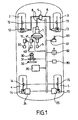
- a vehicle 1 comprises two front wheels 2 and 3 and two rear wheels 4 and 5.
- the hybrid braking system comprises a brake pedal 6 connected to a master cylinder 7.
- the brake pedal 5 When the brake pedal 5 is depressed by the driver wishing that the vehicle is braked, the master cylinder 7 generates a hydraulic overpressure which is propagated via the hydraulic unit 9 and the pipes 8 to the hydraulic brake calipers 12 and 13 fitted respectively to the front wheels 2 and 3.
- the rear wheels 4 and 5 are respectively equipped with electromechanical calipers 14 and 15.
- the hydraulic unit 9 When the driver presses on the brake pedal 6, the hydraulic unit 9 also emits an electric signal S corresponding to the overpressure generated by the master cylinder 7, indicating the value of the longitudinal deceleration D L desired by the driver.
- the electrical signal S is applied to an input of a braking controller 20.
- the braking controller 20 comprises at least one computer and a memory.
- the memory is able to store the instructions of different programs.
- the calculator is able to execute these instructions.
- the controller 20 comprises an input / output interface allowing as input the acquisition of signals coming from different sensors and the storage of the corresponding values in predefined memory spaces, and allowing the output of signals as a function of values read in predefined memory spaces.
- the controller 20 determines whether the brake pedal is depressed (eg S different from the null value). Then, if this is the case, the controller 20 periodically calculates the internal and external target braking forces to be respectively applied by the inner 14 and outer 15 calipers. The controller 20 outputs control signals corresponding to the target braking forces. towards the remote actuators 24 and 25 regulating the actuation of the rear calipers.
- the calculation by the controller 20 of a target braking force consists first of all in determining a basic braking force from the deceleration desired by the driver and corresponding to the depression of the braking force.
- brake pedal then apply different functions to modulate the braking value of based.
- a wheel anti-slip function corrects the basic braking force according to the instantaneous slip value of the wheels.
- a stability control function can increase the basic braking force on one of the wheels to increase the stability of the vehicle engaged in a curve.
- an arbitration device assigns the value of the reference braking force having the highest priority to the target braking force to be transmitted towards the corresponding yoke.
- the vehicle 1 is equipped with a plurality of sensors for measuring the instantaneous value of different variables, so as to define an instantaneous state of the vehicle.
- the steering column 30 is, for example, equipped with a sensor 31 for measuring the steering angle that the driver gives the steering wheel 32.
- the steering angle is zero when the driver wants to go straight and follow a trajectory straight.
- the steering angle is by negative (positive) convention when the driver wishes to turn to the left (right). In the remainder of this document, the turn is to the right and the wheels inside the turn are therefore the wheels 3 and 5.
- the accelerator pedal 40 comprises a sensor 41 for measuring the degree of depression of the pedal. acceleration.
- the clutch pedal 50 comprises a sensor 51 making it possible to determine the state of the clutch: disengaged state in which the engine is coupled to the driving wheels, engaged state in which the engine is decoupled from the driving wheels, and intermediate skid condition wherein the engine torque is only partially applied to the drive wheels.
- the vehicle 1, if it comprises a manual gearbox 60, may be equipped with a sensor 61 to know the position of the gear lever.
- the vehicle 1 further comprises sensors for determining the kinematic state of the vehicle.
- Each of the wheels 2-5 is equipped with a wheel speed sensor 72-75 for measuring the instantaneous speed of rotation of the wheel. This information allows the controller 20 to calculate an instantaneous speed V of the vehicle.
- the vehicle comprises for example a lateral acceleration sensor 80 and a longitudinal acceleration sensor 82.
- the various sensors described are connected to the controller 20 via a network supporting for example the CAN-Bus protocol.
- the method is implemented by the controller 20 executing the instructions of a software for the purpose of managing the braking, the software instructions being stored in the memory of the controller 20.
- the execution of the software starts with the execution of a module A for detecting an input logic condition.
- the instantaneous state of the vehicle is compatible with braking management by means of the method according to the invention.
- Module A begins with a turn test: either the vehicle is already engaged in the turn when the driver is braking, or the vehicle is in a straight line and entering a turn. These two situations are indicated by the instantaneous lateral acceleration measured by the sensor 80.
- the turning test therefore comprises a comparison 110 of comparing the value of the lateral acceleration a 1 with a lateral acceleration threshold of 10, for example 0, 1 g. If the comparison 110 is not verified, the execution of the module A assigns in step 130 the value 0 to a flag FLAG20 thus indicating that the instantaneous state of the vehicle is not compatible with the brake management function according to the invention.
- the turning test is followed by a braking test 140 making it possible to detect whether the driver depresses the brake pedal 6 in order to see the braked vehicle.
- the braking test 140 consists in comparing the current value of the pressure signal S with the zero value. When the pressure signal is other than zero this means that the driver actuates the brake pedal 6. When this braking test is not verified, the execution of the module A goes to step 130. On the other hand, if this braking test 140 is checked while the lateral acceleration condition is also verified, the value 1 is assigned to the FLAG20 variable in step 150.
- Module A is periodically executed to determine whether the instantaneous state of the vehicle is in hand of the braking system by the braking function curve according to the invention.
- Module B is shown in flowchart form in FIG. 2B. It is run periodically. It starts with a step 210 of testing the value of FLAG20 flag read from a memory space whose address is predetermined. If the flag FLAG20 indicates a state compatible with the activation of the brake management according to the invention, the execution of the module B proceeds to step 220.
- step 220 the value of the pressure signal S makes it possible to determine the value of the longitudinal deceleration D L desired by the driver. From the value of the deceleration D L , a base braking force F B is determined in step 230.
- the determination of F B involves the characteristics of the vehicle such as the mass of the body, the stiffness of the body. suspension, etc.
- the base braking force F B was directly applied as the target braking force on the rear wheels, and in particular on the inner rear wheel, the probability would be high that the latter would slip away. This is why a base gain G 0 is applied to the basic braking force F B in step 250 to obtain a corrected braking force F C.
- the amplitude of the corrected braking force F C is smaller than the amplitude of the basic braking force F B.
- the corrected braking force is the same for both rear wheels.
- Step 240 makes it possible to determine the value of the basic gain G 0 as a function of the longitudinal speed V and of the lateral acceleration a 1 of the vehicle. In the preferred embodiment, this determination is made by means of calibration curves stored in the memory of the controller 20. In the case of a controller with more computing capabilities Importantly, the base gain G 0 could be calculated using a function of velocity V and acceleration a 1 .
- FIG. 3 represents a family of calibration curves indexed by values of the lateral acceleration a 1 . These curves give the value of the base gain G 0 as a function of the instantaneous speed V. Below a lower threshold speed V 1 , for example 20 kilometers per hour (km / h), at low speed, the gain of base is weak. Beyond an upper threshold speed V 2 , for example 50 km / h, the base gain G 0 is constant and is a maximum gain dependent on the lateral acceleration a 1 , but always less than unity. The base gain G 0 is both an increasing function of the speed V and decreasing of the acceleration a 1 .
- the corrected braking force F C is a braking force that could be applied directly as the target braking forces on the inner rear wheel and the outer rear wheel.
- a modulation function is used to calculate the internal target braking force from the value of the corrected braking force F C.
- Such a modulation function is shown in FIG. 2C as a flowchart.
- the modulation function uses the temporal variation of the lateral acceleration a 1 given by the sensor 80.
- the lateral acceleration variation a ' 1 is calculated at step 310.
- the instantaneous value of the lateral acceleration variation a 1 is compared in step 320 with a reference acceleration variation which is here the null value. If the lateral acceleration variation a ' 1 is negative, the value of a modulation gain G is brought to unity (step 340).
- the variation of the lateral acceleration a ' 1 is strictly positive, the value of the modulation gain G is calculated in step 330 as a decreasing function of the lateral acceleration variation a' 1 .
- the modulation gain G tends to unity when the lateral acceleration variation a ' 1 tends to zero.
- the modulation gain G tends to zero when the lateral acceleration variation a ' 1 tends towards important values.
- the corrected braking force F C is multiplied by the value of the modulation gain G to determine an internal reference braking force F Rint .
- this reference brake force F Rint is assigned to the braking force Target F target emitted towards the inner rear wheel. It is obvious to those skilled in the art that other ways of modulating the corrected braking force are conceivable and are within the scope of the present invention.
- FIG. 4 reproduces curves representing the time evolution of kinematic magnitudes measured during a test carried out on a vehicle implementing the method according to the invention.
- the curve C 1 represents the speed of the inner rear wheel (speed close to the longitudinal speed of the vehicle if the slip and the angle of the wheel are not taken into account).
- Curve C 2 represents the speed of the outer rear wheel.
- the curve C 3 represents the braking force actually applied to the inner rear wheel.
- the curve C 4 represents the braking force actually applied to the outer rear wheel and which corresponds to the corrected braking force F C.
- Curves C 5 and C 7 (C 6 and C 8 ) correspond to the same physical quantities for the inner front wheel (for the outer front wheel).
- the effect of the modulation of the braking force on the inner wheel is manifested by the fact that the curve C 3 is below the curve C 4 , and this as long as the lateral acceleration variation is positive.
- the braking management is identical in the case where the vehicle is in a turn then the driver brakes and in the case where the driver brakes then turns the steering wheel to approach a turn;
- a different braking management can be considered for both situations.
Abstract
Description
L'invention a pour domaine celui des fonctions de gestion du freinage d'un véhicule équipé d'un système de freinage dans lequel l'actionnement des étriers de frein est découplé de l'enfoncement effectif de la pédale de frein par le conducteur. Plus particulièrement, l'invention a pour domaine celui des fonctions destinées à augmenter la stabilité du véhicule abordant une courbe ou engagé dans une courbe.The subject of the invention is that of brake management functions of a vehicle equipped with a braking system in which the actuation of the brake calipers is decoupled from the effective depression of the brake pedal by the driver. More particularly, the invention relates to that of functions intended to increase the stability of the vehicle approaching a curve or engaged in a curve.
Dans un virage, l'accélération centrifuge est la cause d'un transfert de charge latéral des masses suspendues du véhicule du côté intérieur du virage vers le côté extérieur, conduisant à un mouvement de roulis de la caisse. En conséquence, la répartition du poids du véhicule sur les roues est modifiée et la réaction de la route sur les roues situées du côté intérieur au virage, ou roues intérieures, tend à diminuer alors que la réaction de la route sur les roues situées du côté extérieur au virage, ou roues extérieures, tend à augmenter. La force de freinage, grandeur corrélée à la réaction de la route, qu'il est nécessaire d'appliquer sur une roue intérieure pour stopper son mouvement de rotation est réduite par rapport à la force de freinage qu'il est nécessaire d'appliquer sur une roue extérieure. Dans un cas limite, le transfert de charge est tel que la roue intérieure quitte le contact avec la route et il suffit d'une force de freinage de quelques Newtons pour stopper son mouvement de rotation.In a turn, the centrifugal acceleration is the cause of a lateral load transfer of the suspended masses of the vehicle from the inside of the turn to the outer side, leading to a rolling movement of the body. As a result, the weight distribution of the vehicle on the wheels is changed and the reaction of the road on the wheels on the inner side to the turn, or inner wheels, tends to decrease while the reaction of the road on the wheels on the side outside the turn, or outer wheels, tends to increase. The braking force, a magnitude correlated to the reaction of the road, which it is necessary to apply to an inner wheel to stop its rotational movement is reduced compared to the braking force that is necessary to apply to an outer wheel. In a limited case, the load transfer is such that the inner wheel leaves the contact with the road and it only takes a braking force of a few Newtons to stop its rotational movement.
Lorsque le conducteur freine en virage, si la force de freinage souhaitée par le conducteur était appliquée directement aux roues intérieures, cela augmenterait le glissement de celles-ci, avec la forte probabilité de conduire au blocage de celles-ci.When the driver brakes in a turn, if the braking force desired by the driver was applied directly to the inner wheels, this would increase the sliding of the latter, with the high probability of leading to the blocking thereof.
Par ailleurs, si la roue est en contact glissant avec la route, la composante tangentielle latérale de la réaction du sol sur la roue s'annule. Or c'est précisément cette composante qui permet au véhicule de tourner et de suivre une trajectoire courbe. Le pneumatique perd alors son pouvoir latéral par rapport au sol, et ceci d'autant plus qu'une force de freinage, qui est une force tangentielle longitudinale, est appliquée sur le pneumatique de manière à augmenter le glissement de la roue. En d'autres termes, un véhicule peut soit freiner beaucoup soit tourner beaucoup. Donc le glissement de la roue intérieure lors du freinage entraîne une perte du pouvoir latérale du pneumatique et donc l'instabilité du véhicule qui a tendance à ouvrir sa trajectoire.On the other hand, if the wheel is in sliding contact with the road, the lateral tangential component of the ground reaction on the wheel is canceled. But it is precisely this component that allows the vehicle to turn and follow a curved path. The tire then loses its lateral power relative to the ground, and this especially as a braking force, which is a longitudinal tangential force, is applied to the tire so as to increase the sliding of the wheel. In other words, a vehicle can either brake a lot or turn a lot. Thus the slippage of the inner wheel during braking causes a loss of the lateral power of the tire and therefore the instability of the vehicle which tends to open its trajectory.
Il est connu d'équiper les véhicules avec une fonction dite de contrôle de stabilité (ESP pour « Electronic Stability Program ») contrôlant la stabilité du véhicule dans les courbes. L'angle de lacet est l'angle entre l'axe longitudinal du véhicule et la tangente à la trajectoire souhaitée par le conducteur. Cette dernière est déterminée entre autre par l'angle de braquage du volant de direction. Lorsque l'angle de lacet est trop important, la fonction de contrôle de stabilité déclenche soit l'application d'un couple moteur supplémentaire soit un freinage supplémentaire. Ce freinage supplémentaire appliqué sur l'une des roues crée un moment autour de l'axe de lacet, axe vertical passant par le centre de gravité du véhicule. Ce moment supplémentaire a pour effet de faire tourner le véhicule autour de l'axe de lacet et de réduire l'angle de lacet de manière à retrouver une trajectoire stable.It is known to equip vehicles with a function called stability control (ESP for "Electronic Stability Program") controlling the stability of the vehicle in the curves. The yaw angle is the angle between the longitudinal axis of the vehicle and the tangent to the path desired by the driver. The latter is determined inter alia by the steering angle of the steering wheel. When the yaw angle is too great, the stability control function triggers either the application of additional engine torque or additional braking. This additional braking applied on one of the wheels creates a moment around the yaw axis, vertical axis passing through the center of gravity of the vehicle. This additional moment has the effect of turning the vehicle around the yaw axis and reduce the yaw angle so as to find a stable path.
La fonction de contrôle de stabilité, qui est une fonction de sécurité, est une fonction qui se déclenche dans des conditions extrêmes. Les seuils de déclenchement possèdent des valeurs élevées. De plus, le mode d'action consistant à freiner fortement sur l'une des roues pour remettre le véhicule sur la trajectoire correcte est brusque. Les passager du véhicule ressentent l'actionneme nt de la fonction ESP ce qui nuit à leur confort.The stability control function, which is a safety function, is a function that is triggered under extreme conditions. Trigger thresholds have high values. In addition, the mode of action of strongly braking on one of the wheels to put the vehicle on the correct path is abrupt. The passenger of the vehicle feels the power of the ESP function which affects their comfort.
Il y a donc un besoin pour un système de freinage mettant en oeuvre un procédé permettant d'augment er à moindre coût la stabilité du véhicule en virage, alors que le conducteur freine, avant que les conditions pour le déclenchement d' une fonction ESP ne soient réunies. Un tel sytème est décrit dans le document US6406104. L'invention a pour objet un procédé de gestion du freinage pour augmenter la stabilité d'un véhicule en virage alors que le conducteur enfonce une pédale de frein pour atteindre une décélération souhaitée, le véhicule étant équipé d'un système de freinage comportant des étriers de frein actionnables en fonction d'une force de freinage cible et dans lequel au moins l'actionnement des étriers de frein équipant les roues arrière est découplé de l'enfoncement de la pédale de frein, caractérisé en ce qu'il comporte les étapes consistant à :
- Détecter une condition logique d'entrée comportant au moins un test de virage et un test de freinage; et tant que la condition logique d'entrée est vérifiée,
- Déterminer une force de freinage de base à partir de la décélération souhaitée ;
- Calculer, pour les roues intérieure et extérieure, une force de freinage corrigée à partir de la force de freinage de base pour que la force de freinage corrigée soit réduite par rapport à la force de freinage de base ;
- Moduler, pour la roue intérieure, la force de freinage corrigée pour obtenir une force de freinage de référence intérieure qui soit réduite par rapport à la force de freinage corrigée ; et,
- Appliquer la force de freinage corrigée en tant que force de freinage cible pour la roue arrière extérieure et la force de freinage de référence intérieure en tant que force de freinage cible sur la roue intérieure.
- Detecting an input logic condition including at least one cornering test and a braking test; and as long as the logical input condition is verified,
- Determine a basic braking force from the desired deceleration;
- Calculating, for the inner and outer wheels, a corrected braking force from the base braking force so that the corrected braking force is reduced with respect to the base braking force;
- Modulating, for the inner wheel, the corrected braking force to obtain an internal reference braking force which is reduced relative to the corrected braking force; and,
- Apply the corrected braking force as the target braking force for the outer rear wheel and the internal reference braking force as the target braking force on the inner wheel.
Cette étape de modulation consistant à déterminer la variation temporelle d'accélération latérale ; à comparer la variation d'accélération latérale à une variation seuil ; et, lorsque la variation d'accélération latérale est supérieure à ladite variation seuil, à calculer un gain de modulation qui est inférieur à l'unité et qui est une fonction décroissante de la variation d'accélération latérale ; et, à multiplier la force de freinage corrigée par le gain de modulation pour obtenir la force de freinage de référence intérieure.This modulation step of determining the temporal variation of lateral acceleration; comparing the variation in lateral acceleration with a threshold variation; and, when the lateral acceleration variation is greater than said threshold variation, calculating a modulation gain which is less than unity and which is a decreasing function of the lateral acceleration variation; and, multiplying the braking force corrected by the modulation gain to obtain the internal reference braking force.
De préférence, à l'étape de détection d'une condition logique d'entrée, le test de freinage est vérifié dès que la pédale de frein est enfoncée.Preferably, at the step of detecting an input logic condition, the braking test is checked as soon as the brake pedal is depressed.
De préférence, à l'étape de calcul d'une force de freinage de base corrigée, la force de freinage de base est multipliée par un gain d'où résulte la force de freinage corrigée.Preferably, at the step of calculating a corrected basic braking force, the base braking force is multiplied by a gain from which the corrected braking force results.
De préférence, le gain de base est une fonction croissante d'une vitesse instantanée du véhicule. De préférence encore, le gain de base est une fonction décroissante d'une accélération latérale du véhicule.Preferably, the base gain is an increasing function of an instantaneous vehicle speed. More preferably, the base gain is a decreasing function of a lateral acceleration of the vehicle.
L'invention a également pour objet un logiciel de gestion du freinage contenant des instructions propres à être lues et stockées sur un support, lesdites instructions étant exécutables par un ordinateur hôte, caractérisé en ce que ledit logiciel met en oeuvre un procédé tel décrit ci-dessus.The invention also relates to a brake management software containing instructions that can be read and stored on a medium, said instructions being executable by a host computer, characterized in that said software implements a method as described above.
L'invention a pour objet un contrôleur de freinage programmable mettant en oeuvre un procédé tel décrit ci-dessus, dans un véhicule équipé d'un système de freinage comportant des étriers de frein aptes à être actionnés en fonction d'une force de freinage cible et dans lequel au moins l'actionnement des étriers de frein équipant les roues arrière est découplé de l'enfoncement d'une pédale de frein, enfoncement correspondant à une décélération souhaitée par le conducteur, le contrôleur comportant un espace mémoire apte à stocker des instructions d'un logiciel, un calculateur apte à exécuter les instructions et une interface d'entrée/sortie connectable en entrée à une pluralité de capteurs dont est équipé le véhicule et en sortie à des unités d'actionnement d'étrier de frein, caractérisé en ce que le contrôleur est programmé pour comporter :
- un moyen de détection d'une condition logique d'entrée comportant un moyen de test d'une condition de virage et un moyen de test d'une condition de freinage, le moyen de test d'une condition de virage permettant de vérifier qu'une accélération latérale mesurée par un capteur d'accélération est supérieure à une accélération latérale seuil, et le moyen de test d'une condition de freinage permettant de vérifier que la pédale de frein est enfoncée ;
- Un moyen de détermination d'une force de freinage de base à partir de ladite décélération souhaitée ;
- Un moyen de calcul d'une force de freinage corrigée apte à corriger la force de freinage de base de sorte que la valeur de la force de freinage corrigée soit réduite par rapport à la valeur de la force de freinage de base ;
- Un moyen de modulation apte à moduler la force de freinage corrigée en fonction d'une variation d'accélération latérale de manière à obtenir une force de freinage de référence intérieure qui soit réduite par rapport à la force de freinage corrigée ; et,
- Un moyen d'émission de la force de freinage corrigée en tant que force de freinage cible pour la roue arrière extérieure, et de la force de freinage de référence intérieure en tant que force de freinage cible pour la roue arrière intérieure
- means for detecting an input logic condition including means for testing a turning condition and means for testing a braking condition, means for testing a turning condition for verifying that a lateral acceleration measured by an acceleration sensor is greater than a threshold lateral acceleration, and the braking condition test means for verifying that the brake pedal is depressed;
- Means for determining a base braking force from said desired deceleration;
- Means for calculating a corrected braking force capable of correcting the base braking force so that the value of the corrected braking force is reduced with respect to the value of the basic braking force;
- Modulating means adapted to modulate the corrected braking force according to a lateral acceleration variation so as to obtain an internal reference braking force which is reduced with respect to the corrected braking force; and,
- A means for outputting the corrected braking force as the target braking force for the outer rear wheel, and the inner reference braking force as the target braking force for the inner rear wheel
L'invention a également pour objet un système de freinage pour véhicule comportant un contrôleur de freinage, des unités d'actionnement d'étriers de frein, et au moins des étriers de frein électromécaniques équipant des roues arrière du véhicule, caractérisé en ce que le contrôleur de freinage est un contrôleur de freinage programmable tel que décrit ci-dessus.The invention also relates to a vehicle braking system comprising a brake controller, brake caliper actuating units, and at least electromechanical brake calipers fitted to the rear wheels of the vehicle, characterized in that the braking controller is a programmable braking controller as described above.
L'invention a pour objet, un véhicule comportant un système de freinage caractérisé en ce que le système de freinage est un système de freinage tel que décrit ci-dessus.The subject of the invention is a vehicle comprising a braking system, characterized in that the braking system is a braking system as described above.
L'invention sera mieux comprise, et d'autres buts, détails, caractéristiques et avantages de celle-ci apparaîtront plus clairement au cours de la description suivante d'un mode de réalisation particulier de l'invention, donné uniquement à titre illustratif et non limitatif, en référence aux dessins annexés. Sur ces dessins :
- la figure 1 représente schématiquement un véhicule équipé d'un système de freinage hybride ;
- les figures 2A, 2B et 2C représentent, sous la forme d'organigrammes, les différentes étapes d'un mode de réalisation du procédé selon l'invention ;
- la figure 3 représente une famille de courbes, indexée par l'accélération latérale, donnant le gain de base en fonction de la vitesse du véhicule ;
- la figure 4 représente les forces de freinage et les vitesses des roues arrière intérieure et extérieure au cours d'un essai dans lequel le procédé selon l'invention est actif.
- Figure 1 shows schematically a vehicle equipped with a hybrid braking system;
- FIGS. 2A, 2B and 2C represent, in the form of flow charts, the various steps of an embodiment of the method according to the invention;
- FIG. 3 represents a family of curves, indexed by the lateral acceleration, giving the basic gain as a function of the speed of the vehicle;
- FIG. 4 represents the braking forces and the speeds of the inner and outer rear wheels during a test in which the method according to the invention is active.
L'augmentation de la stabilité en virage passe par la réduction de la valeur de la force de freinage effectivement appliquée aux roues intérieures. Ainsi, une roue intérieure sera moins sujette au glissement et le véhicule conservera au maximum sa faculté de virer et sa stabilité.Increasing cornering stability involves reducing the value of the braking force actually applied to the inner wheels. Thus, an inner wheel will be less prone to slip and the vehicle will retain maximum ability to turn and stability.
Puisque la force de freinage effectivement appliquée sur les roues intérieures ne correspond pas à la force de freinage souhaitée par le conducteur, le procédé selon l'invention ne peut être mis en oeuvre que dans un véhicule comportant un système de freinage découplé de l'actionnement de la pédale de frein, tout au moins pour l'actionnement des étriers de frein équipant les roues arrière. Le véhicule dans lequel l'invention est mise en oeuvre est de préférence un véhicule comportant un système de freinage hybride, mais pourrait également être un véhicule comportant un système de freinage entièrement géré électroniquement.Since the braking force actually applied to the inner wheels does not correspond to the braking force desired by the driver, the method according to the invention can be implemented only in a vehicle comprising a braking system decoupled from the actuation. of the brake pedal, at least for the actuation of the brake calipers fitted to the rear wheels. The vehicle in which the invention is implemented is preferably a vehicle comprising a hybrid braking system, but could also be a vehicle with a braking system fully electronically managed.
Un véhicule 1 comporte deux roues avant 2 et 3 et deux roues arrière 4 et 5. Le système de freinage hybride comporte une pédale de frein 6 reliée à un maître cylindre 7. Lorsque la pédale de frein 5 est enfoncée par le conducteur souhaitant que le véhicule soit freiné, le maître cylindre 7 génère une surpression hydraulique qui est propagée via l'unité hydraulique 9 et les canalisations 8 vers les étriers de frein hydrauliques 12 et 13 équipant respectivement les roues avant 2 et 3.A
Les roues arrière 4 et 5 sont respectivement équipées d'étriers électromécaniques 14 et 15. Lorsque le conducteur appuie sur la pédale de frein 6, l'unité hydraulique 9 émet également un signal électrique S correspondant à la surpression générée par le maître cylindre 7, indiquant la valeur de la décélération longitudinale DL souhaitée par le conducteur.The
Le signal électrique S est appliqué sur une entrée d'un contrôleur de freinage 20. Le contrôleur de freinage 20 comporte au moins un calculateur et une mémoire. La mémoire est apte à stocker les instructions de différents programmes. Le calculateur est apte à exécuter ces instructions. Le contrôleur 20 comporte une interface d'entrée/sortie permettant en entrée l'acquisition de signaux provenant de différents capteurs et le stockage des valeurs correspondantes dans des espaces mémoire prédéfinis, et permettant en sortie l'émission de signaux en fonction de valeurs lues dans des espaces mémoire prédéfinis.The electrical signal S is applied to an input of a
En réponse au signal S, le contrôleur 20 détermine si la pédale de frein est enfoncée (par exemple S différent de la valeur nulle). Puis, si tel est le cas, le contrôleur 20 calcule périodiquement les forces de freinage cibles intérieure et extérieure devant être respectivement appliquées par les étriers intérieur 14 et extérieur 15. Le contrôleur 20 émet en sortie des signaux de commande correspondant aux forces de freinage cibles en direction des actionneurs déportés 24 et 25 régulant l'actionnement des étriers arrière.In response to the signal S, the
Plus précisément et de manière connue, le calcul par le contrôleur 20 d'une force de freinage cible consiste d'abord à déterminer une force de freinage de base à partir de la décélération souhaitée par le conducteur et qui correspond à l'enfoncement de la pédale de frein, puis à appliquer différentes fonctions afin de moduler la valeur du freinage de base. Par exemple une fonction d'anti-patinage des roues corrige la force de freinage de base en fonction de la valeur du glissement instantané des roues. Par exemple encore une fonction de contrôle de stabilité peut augmenter la force de freinage de base sur une des roues pour augmenter la stabilité du véhicule engagé dans une courbe. Chacune des ces fonctions, déclenchées en fonction de conditions d'entrée particulières, conduisent au calcul d'une force de freinage de référence ainsi que d'un drapeau indiquant le niveau de priorité de la force de freinage de référence ainsi calculée. Finalement, un dispositif d'arbitrage affecte la valeur de la force de freinage de référence ayant la priorité la plus élevée à la force de freinage cible à émettre en direction de l'étrier correspondant.More specifically and in a known manner, the calculation by the
Par ailleurs, le véhicule 1 est équipé d'une pluralité de capteurs permettant de mesurer la valeur instantanée de différentes variables, de manière à définir un état instantané du véhicule. La colonne de direction 30 est, par exemple, équipée d'un capteur 31 permettant de mesurer l'angle de braquage que le conducteur donne au volant 32. L'angle de braquage est nul lorsque le conducteur souhaite aller tout droit et suivre une trajectoire rectiligne. L'angle braquage est par convention négatif (positif) lorsque le conducteur souhaite tourner vers a gauche (droite). Dans la suite de ce document, le virage est à droite est les roues intérieures au virage sont par conséquent les roues 3 et 5. La pédale d'accélération 40 comporte un capteur 41 permettant de mesurer le degré d'enfoncement de la pédale d'accélération. La pédale d'embrayage 50 comporte un capteur 51 permettant de déterminer l'état de l'embrayage : état débrayé dans lequel le moteur est couplé aux roues motrices, état embrayé dans lequel le moteur est découplé des roues motrices, et état de patinage intermédiaire dans lequel le couple moteur n'est que partiellement appliqué aux roues motrices. Enfin, le véhicule 1, s'il comporte une boîte de vitesses manuelle 60, peut être équipé d'un capteur 61 permettant de connaître la position du levier de vitesses.Furthermore, the
Le véhicule 1 comporte, en outre, des capteurs permettant de déterminer l'état cinématique du véhicule. Chacune des roues 2-5 est équipée d'un capteur de vitesse de roue 72-75 permettant de mesurer la vitesse instantanée de rotation de la roue. Cette information permet au contrôleur 20 de calculer une vitesse instantanée V du véhicule. Pour mesurer l'accélération, le véhicule comporte par exemple un capteur d'accélération latérale 80 et un capteur d'accélération longitudinale 82. Les différents capteurs décrits sont connectés au contrôleur 20, via un réseau supportant par exemple le protocole CAN-Bus.The
En se référant maintenant aux figures 2A, 2B et 2C, les différentes étapes du procédé selon l'invention vont être décrites. De préférence, le procédé est mis en oeuvre par le contrôleur 20 exécutant les instructions d'un logiciel dans le but de gérer le freinage, les instructions du logiciel étant stockées dans la mémoire du contrôleur 20.Referring now to FIGS. 2A, 2B and 2C, the various steps of the method according to the invention will be described. Preferably, the method is implemented by the
Sur la figure 2A, l'exécution du logiciel débute par l'exécution d'un module A de détection d'une condition logique d'entrée. Lorsque cette condition logique d'entrée est vérifiée, l'état instantané du véhicule est compatible avec une gestion du freinage au moyen du procédé selon l'invention. Le module A débute par un test de virage : soit le véhicule est déjà engagé dans le virage au moment où le conducteur freine, soit le véhicule est en ligne droite et aborde un virage. Ces deux situations sont indiquées par l'accélération latérale instantanée mesurée par le capteur 80. Le test de virage comporte donc une comparaison 110 consistant à comparer la valeur de l'accélération latérale a1 avec une accélération latérale seuil a10 par exemple de 0,1 g. Si la comparaison 110 n'est pas vérifiée, l'exécution du module A affecte à l'étape 130 la valeur 0 à un drapeau FLAG20 indiquant ainsi que l'état instantané du véhicule n'est pas compatible avec la fonction de gestion du freinage selon l'invention.In FIG. 2A, the execution of the software starts with the execution of a module A for detecting an input logic condition. When this input logic condition is verified, the instantaneous state of the vehicle is compatible with braking management by means of the method according to the invention. Module A begins with a turn test: either the vehicle is already engaged in the turn when the driver is braking, or the vehicle is in a straight line and entering a turn. These two situations are indicated by the instantaneous lateral acceleration measured by the
En revanche, si la condition est vérifiée, le test de virage est suivi par un test de freinage 140 permettant de détecter si le conducteur enfonce la pédale de frein 6 dans le but de voir le véhicule freiné. Le test de freinage 140 consiste à comparer la valeur actuel du signal de pression S avec la valeur nulle. Lorsque le signal de pression est différent de zéro cela signifie que le conducteur actionne la pédale de frein 6. Lorsque ce test de freinage n'est pas vérifié, l'exécution du module A passe à l'étape 130. En revanche, si ce test de freinage 140 est vérifié alors que la condition d'accélération latérale est également vérifiée, la valeur 1 est affectée à la variable FLAG20 à l'étape 150.On the other hand, if the condition is verified, the turning test is followed by a
Le module A est exécuté périodiquement de manière à déterminer si l'état instantané du véhicule est compatible par une prise en main du système de freinage par la fonction de freinage en courbe selon l'invention.Module A is periodically executed to determine whether the instantaneous state of the vehicle is in hand of the braking system by the braking function curve according to the invention.
Il est à noter que si le conducteur freine alors que le véhicule est déjà engagé dans une courbe la gestion du freinage est déclenchée de manière à augmenter la stabilité du véhicule. La gestion du freinage est également déclenchée lorsqu'il a été anticipé que le véhicule va entrer dans une courbe. Dans le mode de réalisation actuellement préféré, l'anticipation du virage est faite au moyen de l'accélération latérale, mais d'autres variables peuvent être prises en compte pour anticiper cette situation.It should be noted that if the driver brakes while the vehicle is already engaged in a curve braking management is triggered so as to increase the stability of the vehicle. Braking management is also triggered when it is anticipated that the vehicle will enter a curve. In the presently preferred embodiment, the anticipation of the turn is made by means of lateral acceleration, but other variables may be taken into account to anticipate this situation.
Le module B est représenté sous forme d'organigramme sur la figure 2B. Il est exécuté périodiquement. Il débute par une étape 210 consistant à tester la valeur du drapeau FLAG20 lue à partir d'un espace mémoire dont l'adresse est prédéterminée. Si le drapeau FLAG20 indique un état compatible avec l'activation de la gestion des freins selon l'invention, l'exécution du module B passe à l'étape 220.Module B is shown in flowchart form in FIG. 2B. It is run periodically. It starts with a
A l'étape 220 la valeur du signal de pression S permet de déterminer la valeur de la décélération longitudinale DL souhaitée par le conducteur. A partir de la valeur de la décélération DL, une force de freinage de base FB est déterminée à l'étape 230. La détermination de FB fait intervenir les caractéristiques du véhicule telles que la masse de la caisse, la raideur de la suspension, etc.In
Si la force de freinage de base FB était directement appliquée comme force de freinage cible sur les roues arrière, et en particulier sur la roue arrière intérieure, la probabilité serait grande que cette dernière parte en glissement. C'est la raison pour laquelle un gain de base G0 est appliqué à la force de freinage de base FB à l'étape 250 pour obtenir une force de freinage corrigée FC. L'amplitude de la force de freinage corrigée FC est inférieure à l'amplitude de la force de freinage de base FB. Dans le mode de réalisation actuellement envisagé, la force de freinage corrigée est identique pour les deux roues arrière.If the base braking force F B was directly applied as the target braking force on the rear wheels, and in particular on the inner rear wheel, the probability would be high that the latter would slip away. This is why a base gain G 0 is applied to the basic braking force F B in
L'étape 240 permet de déterminer la valeur du gain de base G0 en fonction de la vitesse longitudinale V et de l'accélération latérale a1 du véhicule. Dans le mode de réalisation préféré, cette détermination se fait au moyen de courbes de calibration stockées dans la mémoire du contrôleur 20. Dans le cas d'un contrôleur aux capacités de calcul plus importantes, le gain de base G0 pourrait être calculé en utilisant une fonction de la vitesse V et de l'accélération a1.Step 240 makes it possible to determine the value of the basic gain G 0 as a function of the longitudinal speed V and of the lateral acceleration a 1 of the vehicle. In the preferred embodiment, this determination is made by means of calibration curves stored in the memory of the
La figure 3 représente une famille de courbes de calibration indexée par des valeurs de l'accélération latérale a1. Ces courbes donnent la valeur du gain de base G0 en fonction de la vitesse instantanée V. En deçà d'une vitesse seuil inférieure V1, par exemple de 20 kilomètres par heure (km/h), à basse vitesse, le gain de base est faible. Au delà d'une vitesse seuil supérieure V2, par exemple de 50 km/h, le gain de base G0 est constant et vaut un gain maximum dépendant de l'accélération latérale a1, mais toujours inférieur à l'unité. Le gain de base G0 est à la fois une fonction croissante de la vitesse V et décroissante de l'accélération a1.FIG. 3 represents a family of calibration curves indexed by values of the lateral acceleration a 1 . These curves give the value of the base gain G 0 as a function of the instantaneous speed V. Below a lower threshold speed V 1 , for example 20 kilometers per hour (km / h), at low speed, the gain of base is weak. Beyond an upper threshold speed V 2 , for example 50 km / h, the base gain G 0 is constant and is a maximum gain dependent on the lateral acceleration a 1 , but always less than unity. The base gain G 0 is both an increasing function of the speed V and decreasing of the acceleration a 1 .
La force de freinage corrigée FC est une force de freinage qui pourrait être appliquée directement en tant que forces de freinage cible sur la roue arrière intérieure et sur la roue arrière extérieure. De préférence, une fonction de modulation est utilisée pour calculer la force de freinage cible intérieure à partir de la valeur de la force de freinage corrigée FC. Une telle fonction de modulation est représentée à la figure 2C sous forme d'organigramme.The corrected braking force F C is a braking force that could be applied directly as the target braking forces on the inner rear wheel and the outer rear wheel. Preferably, a modulation function is used to calculate the internal target braking force from the value of the corrected braking force F C. Such a modulation function is shown in FIG. 2C as a flowchart.
La fonction de modulation utilise la variation temporelle de l'accélération latérale a1 donnée par le capteur 80. La variation d'accélération latérale a'1 est calculée à l'étape 310. Puis la valeur instantanée de la variation d'accélération latérale a'1 est comparée, à l'étape 320, à une variation d'accélération de référence qui est ici la valeur nulle. Si la variation d'accélération latérale a'1 est négative, la valeur d'un gain de modulation G est portée à l'unité (étape 340). En revanche si la variation de l'accélération latérale a'1 est strictement positive, la valeur du gain de modulation G est calculée à l'étape 330 en tant que fonction décroissante de la variation d'accélération latérale a'1. Le gain de modulation G tend vers l'unité lorsque la variation d'accélération latérale a'1 tend vers zéro. Le gain de modulation G tend vers zéro lorsque la variation d'accélération latérale a'1 tend vers des valeurs importantes. A l'étape 350 la force de freinage corrigée FC est multipliée par la valeur du gain de modulation G pour déterminer une force de freinage de référence intérieure FRint. A l'étape 360, cette force de freinage de référence intérieure FRint est affectée à la force de freinage cible Fcible émise vers la roue arrière intérieure. Il est évident pour l'homme du métier, que d'autres manières de moduler la force de freinage corrigée sont envisageables et entrent dans la portée de la présente invention.The modulation function uses the temporal variation of the lateral acceleration a 1 given by the
La figure 4 reproduit des courbes représentant l'évolution temporelle de grandeurs cinématiques mesurées au cours d'un essai effectué sur un véhicule mettant en oeuvre le procédé selon l'invention. Sur la figure 4, la courbe C1 représente la vitesse de la roue arrière intérieure (vitesse proche de la vitesse longitudinale du véhicule si le glissement et l'angle de la roue ne sont pas pris en compte). La courbe C2 représente la vitesse de la roue arrière extérieure. La courbe C3 représente la force de freinage effectivement appliquée sur la roue arrière intérieure. La courbe C4 représente la force de freinage effectivement appliquée sur la roue arrière extérieure et qui correspond à la force de freinage corrigée FC. Les courbes C5 et C7 (C6 et C8) correspondent aux mêmes grandeurs physiques pour la roue avant intérieure (pour la roue avant extérieure). L'effet de la modulation de la force de freinage sur la roue intérieure se manifeste par le fait que la courbe C3 est en dessous de la courbe C4, et ceci tant que la variation d'accélération latérale est positive.FIG. 4 reproduces curves representing the time evolution of kinematic magnitudes measured during a test carried out on a vehicle implementing the method according to the invention. In FIG. 4, the curve C 1 represents the speed of the inner rear wheel (speed close to the longitudinal speed of the vehicle if the slip and the angle of the wheel are not taken into account). Curve C 2 represents the speed of the outer rear wheel. The curve C 3 represents the braking force actually applied to the inner rear wheel. The curve C 4 represents the braking force actually applied to the outer rear wheel and which corresponds to the corrected braking force F C. Curves C 5 and C 7 (C 6 and C 8 ) correspond to the same physical quantities for the inner front wheel (for the outer front wheel). The effect of the modulation of the braking force on the inner wheel is manifested by the fact that the curve C 3 is below the curve C 4 , and this as long as the lateral acceleration variation is positive.
Dans le mode de réalisation actuellement préféré, la gestion du freinage est identique dans le cas où le véhicule est dans un virage puis que le conducteur freine et dans le cas où le conducteur freine puis tourne le volant pour aborder un virage ; En variante, une gestion du freinage différente peut être envisagée pour les deux situations.In the presently preferred embodiment, the braking management is identical in the case where the vehicle is in a turn then the driver brakes and in the case where the driver brakes then turns the steering wheel to approach a turn; Alternatively, a different braking management can be considered for both situations.
Bien que l'invention ait été décrite en liaison avec un mode de réalisation particulier, il est bien évident qu'elle n'y est nullement limitée à celui-ci et qu'elle comprend tous les équivalents techniques des moyens décrits ainsi que leurs combinaisons si ceux- et celles-ci entrent dans le cadre de l'invention, telle que définie dans les revendications.Although the invention has been described in connection with a particular embodiment, it is obvious that it is in no way limited to it and that it comprises all the technical equivalents of the means described and their combinations if these are within the scope of the invention as defined in the claims.
Claims (9)
- Braking management method for increasing the stability of a vehicle when cornering while the driver presses a brake pedal (6) to achieve a desired deceleration (DL), the vehicle being fitted with a braking system comprising brake callipers (14, 15) that can be actuated as a function of a target braking force (Ftarget) and in which at least the actuation of the brake callipers fitted to the rear wheels (4, 5) is decoupled from the pressing of the said brake pedal, the said method comprising the steps consisting in:- detecting an input logic condition comprising at least a cornering test (110, 120) and a braking test (140); and provided that the said input logic condition is verified (210),- determining (220, 230) a base braking force (FB) from the desired deceleration;- computing (240, 250), for the inside and outside wheels, a corrected braking force (FC) from the said base braking force so that the corrected braking force is less than the base braking force;- modulating (350), for the said inside wheel, the said corrected braking force to obtain an inside reference braking force (FRint) that is less than the corrected braking force; and,- applying the said corrected braking force as the target braking force for the outside rear wheel and the said inside reference braking force as the target braking force on the inside wheel,characterized in that the said modulation step consists in:- determining the temporal variation of lateral acceleration (a'1);- comparing the variation of lateral acceleration with a threshold variation; and, when the variation of lateral acceleration is greater than the said threshold variation,- computing a modulation gain (G) that is less than unity and that is a decreasing function of the variation of lateral acceleration; and,- multiplying the said corrected braking force by the said modulation gain to obtain the said inside reference braking force.
- Method according to Claim 1, characterized in that, at the step of detecting an input logic condition, the said cornering test is verified when an instantaneous lateral acceleration (a1) of the said vehicle is greater than a threshold lateral acceleration (a10).
- Method according to Claim 1, characterized in that, at the step of detecting an input logic condition, the said braking test is verified as soon as the said brake pedal is pressed.
- Method according to one of Claims 1 to 3, characterized in that, at the step of computing a corrected base braking force, the said base braking force (FB) is multiplied by a gain (G0) from which the said corrected braking force (FC) is derived.
- Method according to Claim 4, characterized in that the said base gain (G0) is an increasing function of a longitudinal velocity (V) of the said vehicle and a decreasing function of a lateral acceleration (a1) of the said vehicle.
- Braking management software containing instructions suitable for being read and stored on a medium, the said instructions being executable by a host computer, characterized in that the said software uses a method according to one of Claims 1 to 5.
- Programmable braking controller using a method according to one of Claims 1 to 5 in a vehicle fitted with a braking system comprising brake callipers (14, 15) capable of being actuated as a function of a target braking force (Ftarget) and in which at least the actuation of the brake callipers fitted to the rear wheels (4, 5) is decoupled from the pressing of a brake pedal (6), a pressing corresponding to a deceleration (DL) desired by the driver, the said controller (20) comprising a memory space capable of storing software instructions, a computer capable of executing the said instructions and an input/output interface that can be connected at the input to a plurality of sensors with which the said vehicle is fitted and at the output to brake calliper actuation units, the said controller being programmed to comprise:- a means (A) for detecting an input logic condition comprising a means of testing a cornering condition (110, 120) and a means of testing a braking condition (140), the said means of testing a cornering condition making it possible to verify that a lateral acceleration measured by an acceleration sensor is greater than a threshold lateral acceleration, and the said means of testing a braking condition making it possible to verify that the said brake pedal is pressed;- a means (220, 230) of determining a base braking force (FB) from the said desired deceleration;- a means (240, 250) of computing a corrected braking force (FC) capable of correcting the said base braking force so that the value of the corrected braking force is less than the value of the base braking force;- a modulation means capable of modulating the said corrected braking force so as to obtain an inside reference braking force (FRint) that is less than the corrected braking force; and- a means of transmitting the said corrected braking force as a target braking force for the outside rear wheel, and of the said inside reference braking force as the target braking force for the inside rear wheel,characterized in that the said modulation means is capable of modulating the said corrected braking force as a function of a variation of lateral acceleration (a'1).
- Vehicle braking system comprising a braking controller (20), brake calliper actuation units (24, 25) and at least electromechanical brake callipers (14, 15) fitted to the rear wheels (4, 5) of the said vehicle, characterized in that the said braking controller is a programmable braking controller according to Claim 7.
- Vehicle comprising a braking system, characterized in that the said braking system is a braking system according to Claim 8.
Priority Applications (5)
| Application Number | Priority Date | Filing Date | Title |
|---|---|---|---|
| EP04291895A EP1621432B1 (en) | 2004-07-26 | 2004-07-26 | Apparatus and method for right/left braking force distribution at cornering |
| DE602004003235T DE602004003235T2 (en) | 2004-07-26 | 2004-07-26 | Device and method for brake control of the inner and outer wheels in a curve braking |
| AT04291895T ATE345252T1 (en) | 2004-07-26 | 2004-07-26 | DEVICE AND METHOD FOR BRAKE CONTROL OF THE INDOOR OR OUTER WHEELS DURING CURVING BRAKES |
| JP2005213009A JP4328746B2 (en) | 2004-07-26 | 2005-07-22 | Method and apparatus for managing inner and outer brakes for deceleration vehicle during bend running |
| US11/188,573 US20060163940A1 (en) | 2004-07-26 | 2005-07-25 | Process and device for management of inside and outside braking for a decelerating vehicle taking a bend |
Applications Claiming Priority (1)
| Application Number | Priority Date | Filing Date | Title |
|---|---|---|---|
| EP04291895A EP1621432B1 (en) | 2004-07-26 | 2004-07-26 | Apparatus and method for right/left braking force distribution at cornering |
Publications (2)
| Publication Number | Publication Date |
|---|---|
| EP1621432A1 EP1621432A1 (en) | 2006-02-01 |
| EP1621432B1 true EP1621432B1 (en) | 2006-11-15 |
Family
ID=34931284
Family Applications (1)
| Application Number | Title | Priority Date | Filing Date |
|---|---|---|---|
| EP04291895A Not-in-force EP1621432B1 (en) | 2004-07-26 | 2004-07-26 | Apparatus and method for right/left braking force distribution at cornering |
Country Status (5)
| Country | Link |
|---|---|
| US (1) | US20060163940A1 (en) |
| EP (1) | EP1621432B1 (en) |
| JP (1) | JP4328746B2 (en) |
| AT (1) | ATE345252T1 (en) |
| DE (1) | DE602004003235T2 (en) |
Families Citing this family (5)
| Publication number | Priority date | Publication date | Assignee | Title |
|---|---|---|---|---|
| JP4909790B2 (en) * | 2007-04-04 | 2012-04-04 | 本田技研工業株式会社 | Vehicle travel control device |
| DE102007044396A1 (en) * | 2007-09-18 | 2009-03-26 | Continental Automotive Gmbh | Method and device for assigning a wheel of a motor vehicle |
| FR2925004B1 (en) * | 2007-12-14 | 2010-05-21 | Peugeot Citroen Automobiles Sa | BRAKE CONTROL METHOD AND DEVICE |
| KR101350845B1 (en) * | 2009-09-15 | 2014-01-14 | 주식회사 만도 | Apparatus And Method For Adjusting Clearance Of Electronic Brake |
| DE102015009160A1 (en) | 2015-07-14 | 2017-01-19 | Wabco Gmbh | Method and device for electronically controlling a vehicle deceleration of a vehicle with brake slip control |
Family Cites Families (6)
| Publication number | Priority date | Publication date | Assignee | Title |
|---|---|---|---|---|
| DE3413738C2 (en) * | 1984-04-12 | 1993-11-04 | Teves Gmbh Alfred | SLIP CONTROL BRAKE SYSTEM FOR ROAD VEHICLES |
| JP2753793B2 (en) * | 1993-06-03 | 1998-05-20 | 本田技研工業株式会社 | Method for controlling front and rear force of vehicle wheels |
| DE19539345A1 (en) * | 1995-10-23 | 1997-04-24 | Bayerische Motoren Werke Ag | ABS and / or ASC control system for motor vehicles |
| DE19651460A1 (en) * | 1996-12-11 | 1998-06-18 | Bosch Gmbh Robert | Method and device for controlling the brake force distribution in a vehicle |
| DE19732998A1 (en) * | 1997-07-31 | 1999-02-04 | Itt Mfg Enterprises Inc | Method and device for detecting a braking situation |
| FR2775237B1 (en) * | 1998-02-26 | 2000-04-07 | Renault | METHOD FOR CONTROLLING THE BRAKING SETPOINT ON THE WHEELS OF A VEHICLE |
-
2004
- 2004-07-26 EP EP04291895A patent/EP1621432B1/en not_active Not-in-force
- 2004-07-26 DE DE602004003235T patent/DE602004003235T2/en active Active
- 2004-07-26 AT AT04291895T patent/ATE345252T1/en not_active IP Right Cessation
-
2005
- 2005-07-22 JP JP2005213009A patent/JP4328746B2/en active Active
- 2005-07-25 US US11/188,573 patent/US20060163940A1/en not_active Abandoned
Also Published As
| Publication number | Publication date |
|---|---|
| DE602004003235T2 (en) | 2007-09-06 |
| DE602004003235D1 (en) | 2006-12-28 |
| US20060163940A1 (en) | 2006-07-27 |
| JP2006036196A (en) | 2006-02-09 |
| EP1621432A1 (en) | 2006-02-01 |
| JP4328746B2 (en) | 2009-09-09 |
| ATE345252T1 (en) | 2006-12-15 |
Similar Documents
| Publication | Publication Date | Title |
|---|---|---|
| EP2137043B1 (en) | Hill start assistance method for motor vehicles | |
| EP3145783B1 (en) | Method for controlling a power train of a vehicle, and corresponding device and vehicle | |
| FR2624070A1 (en) | METHOD FOR DETERMINING SLIDING THRESHOLDS FOR A DRIVING SLIDER CONTROL SYSTEM OF A MOTOR VEHICLE AND DEVICE FOR IMPLEMENTING SAME | |
| EP2555939B1 (en) | System and method for limiting the engine torque of a four-wheel-drive vehicle | |
| EP1593566A1 (en) | Aiding function for the pulling away of a vehicle on a slope | |
| EP1584530A1 (en) | Method and device for assisted vehicle hill descent | |
| EP1621432B1 (en) | Apparatus and method for right/left braking force distribution at cornering | |
| JP2002525241A (en) | Apparatus and method for limiting backward rolling speed of automobile | |
| EP1621431B1 (en) | Method and system for front/rear brake force distribution for a motor vehicle | |
| EP2558320B1 (en) | System and method of controlling a torque transfer actuator in multiple function modes | |
| FR2858032A1 (en) | Motor vehicle starting assistance method, involves increasing effective engine torque up to level of consigned engine torque when drivers behavior is detected and when effective torque is less than consigned torque | |
| EP2307253B1 (en) | Device for evaluating the transverse acceleration of a motor vehicle and corresponding method | |
| EP1659042B1 (en) | Vehicle driving assistance, method and system | |
| EP1593567B1 (en) | Driving aid function when following a line of vehicles | |
| FR2915802A1 (en) | Wheel's adhesion determining method for motor vehicle, involves applying braking action on one of wheels of vehicle, measuring parameter varying according to brake, and determining value of adhesion coefficient from measured parameter | |
| FR2857925A1 (en) | Surface slope estimating method for motor vehicle, involves producing quantitative estimation signal of slope when frost condition for slope measurement is verified and congealing estimation signal when frost condition is verified | |
| JP4551039B2 (en) | Braking force control device | |
| WO2004031011A2 (en) | Braking system and method for producing a deceleration setpoint for motor vehicle brake actuators | |
| FR2892081A1 (en) | DEVICE FOR MAINTAINING A MOTOR VEHICLE IN PLACE IN A SLOPE, METHOD FOR OPERATING SUCH A DEVICE AND MOTOR VEHICLE EQUIPPED WITH SUCH A DEVICE | |
| WO2011138548A2 (en) | Transmission system with neutral-shaft-type differential comprising regenerative braking device | |
| FR3138095A1 (en) | Motor vehicle braking curve mapping | |
| EP2555938A1 (en) | Method for controlling the operation of a means for mechanically coupling first and second axles of a motor vehicle | |
| FR2936984A1 (en) | Automatic regulation system i.e. anti-skid regulation system, for regulating driveability of motor vehicle, has storage unit to storing engine overspeed regulation torque, and selection unit selecting torque to be applied to output | |
| WO2018007695A1 (en) | Motor vehicle parking brake control device | |
| EP1136335A1 (en) | Adaptive braking torque modulation method |
Legal Events
| Date | Code | Title | Description |
|---|---|---|---|
| PUAI | Public reference made under article 153(3) epc to a published international application that has entered the european phase |
Free format text: ORIGINAL CODE: 0009012 |
|
| 17P | Request for examination filed |
Effective date: 20050430 |
|
| AK | Designated contracting states |
Kind code of ref document: A1 Designated state(s): AT BE BG CH CY CZ DE DK EE ES FI FR GB GR HU IE IT LI LU MC NL PL PT RO SE SI SK TR |
|
| AX | Request for extension of the european patent |
Extension state: AL HR LT LV MK |
|
| GRAP | Despatch of communication of intention to grant a patent |
Free format text: ORIGINAL CODE: EPIDOSNIGR1 |
|
| GRAS | Grant fee paid |
Free format text: ORIGINAL CODE: EPIDOSNIGR3 |
|
| AKX | Designation fees paid |
Designated state(s): AT BE BG CH CY CZ DE DK EE ES FI FR GB GR HU IE IT LI LU MC NL PL PT RO SE SI SK TR |
|
| GRAA | (expected) grant |
Free format text: ORIGINAL CODE: 0009210 |
|
| AK | Designated contracting states |
Kind code of ref document: B1 Designated state(s): AT BE BG CH CY CZ DE DK EE ES FI FR GB GR HU IE IT LI LU MC NL PL PT RO SE SI SK TR |
|
| PG25 | Lapsed in a contracting state [announced via postgrant information from national office to epo] |
Ref country code: SI Free format text: LAPSE BECAUSE OF FAILURE TO SUBMIT A TRANSLATION OF THE DESCRIPTION OR TO PAY THE FEE WITHIN THE PRESCRIBED TIME-LIMIT Effective date: 20061115 Ref country code: RO Free format text: LAPSE BECAUSE OF FAILURE TO SUBMIT A TRANSLATION OF THE DESCRIPTION OR TO PAY THE FEE WITHIN THE PRESCRIBED TIME-LIMIT Effective date: 20061115 Ref country code: NL Free format text: LAPSE BECAUSE OF FAILURE TO SUBMIT A TRANSLATION OF THE DESCRIPTION OR TO PAY THE FEE WITHIN THE PRESCRIBED TIME-LIMIT Effective date: 20061115 Ref country code: CZ Free format text: LAPSE BECAUSE OF FAILURE TO SUBMIT A TRANSLATION OF THE DESCRIPTION OR TO PAY THE FEE WITHIN THE PRESCRIBED TIME-LIMIT Effective date: 20061115 Ref country code: FI Free format text: LAPSE BECAUSE OF FAILURE TO SUBMIT A TRANSLATION OF THE DESCRIPTION OR TO PAY THE FEE WITHIN THE PRESCRIBED TIME-LIMIT Effective date: 20061115 Ref country code: PL Free format text: LAPSE BECAUSE OF FAILURE TO SUBMIT A TRANSLATION OF THE DESCRIPTION OR TO PAY THE FEE WITHIN THE PRESCRIBED TIME-LIMIT Effective date: 20061115 Ref country code: AT Free format text: LAPSE BECAUSE OF FAILURE TO SUBMIT A TRANSLATION OF THE DESCRIPTION OR TO PAY THE FEE WITHIN THE PRESCRIBED TIME-LIMIT Effective date: 20061115 Ref country code: SK Free format text: LAPSE BECAUSE OF FAILURE TO SUBMIT A TRANSLATION OF THE DESCRIPTION OR TO PAY THE FEE WITHIN THE PRESCRIBED TIME-LIMIT Effective date: 20061115 Ref country code: IE Free format text: LAPSE BECAUSE OF FAILURE TO SUBMIT A TRANSLATION OF THE DESCRIPTION OR TO PAY THE FEE WITHIN THE PRESCRIBED TIME-LIMIT Effective date: 20061115 |
|
| REG | Reference to a national code |
Ref country code: GB Ref legal event code: FG4D Free format text: NOT ENGLISH |
|
| REG | Reference to a national code |
Ref country code: CH Ref legal event code: EP |
|
| REF | Corresponds to: |
Ref document number: 602004003235 Country of ref document: DE Date of ref document: 20061228 Kind code of ref document: P |
|
| REG | Reference to a national code |
Ref country code: IE Ref legal event code: FG4D Free format text: LANGUAGE OF EP DOCUMENT: FRENCH |
|
| PG25 | Lapsed in a contracting state [announced via postgrant information from national office to epo] |
Ref country code: BG Free format text: LAPSE BECAUSE OF FAILURE TO SUBMIT A TRANSLATION OF THE DESCRIPTION OR TO PAY THE FEE WITHIN THE PRESCRIBED TIME-LIMIT Effective date: 20070215 Ref country code: SE Free format text: LAPSE BECAUSE OF FAILURE TO SUBMIT A TRANSLATION OF THE DESCRIPTION OR TO PAY THE FEE WITHIN THE PRESCRIBED TIME-LIMIT Effective date: 20070215 Ref country code: DK Free format text: LAPSE BECAUSE OF FAILURE TO SUBMIT A TRANSLATION OF THE DESCRIPTION OR TO PAY THE FEE WITHIN THE PRESCRIBED TIME-LIMIT Effective date: 20070215 |
|
| PG25 | Lapsed in a contracting state [announced via postgrant information from national office to epo] |
Ref country code: ES Free format text: LAPSE BECAUSE OF FAILURE TO SUBMIT A TRANSLATION OF THE DESCRIPTION OR TO PAY THE FEE WITHIN THE PRESCRIBED TIME-LIMIT Effective date: 20070226 |
|
| PG25 | Lapsed in a contracting state [announced via postgrant information from national office to epo] |
Ref country code: PT Free format text: LAPSE BECAUSE OF FAILURE TO SUBMIT A TRANSLATION OF THE DESCRIPTION OR TO PAY THE FEE WITHIN THE PRESCRIBED TIME-LIMIT Effective date: 20070416 |
|
| NLV1 | Nl: lapsed or annulled due to failure to fulfill the requirements of art. 29p and 29m of the patents act | ||
| GBV | Gb: ep patent (uk) treated as always having been void in accordance with gb section 77(7)/1977 [no translation filed] |
Effective date: 20061115 |
|
| REG | Reference to a national code |
Ref country code: IE Ref legal event code: FD4D |
|
| PLBE | No opposition filed within time limit |
Free format text: ORIGINAL CODE: 0009261 |
|
| STAA | Information on the status of an ep patent application or granted ep patent |
Free format text: STATUS: NO OPPOSITION FILED WITHIN TIME LIMIT |
|
| 26N | No opposition filed |
Effective date: 20070817 |
|
| PG25 | Lapsed in a contracting state [announced via postgrant information from national office to epo] |
Ref country code: GB Free format text: LAPSE BECAUSE OF FAILURE TO SUBMIT A TRANSLATION OF THE DESCRIPTION OR TO PAY THE FEE WITHIN THE PRESCRIBED TIME-LIMIT Effective date: 20061115 |
|
| BERE | Be: lapsed |
Owner name: DELPHI TECHNOLOGIES, INC. Effective date: 20070731 Owner name: PEUGEOT CITROEN AUTOMOBILES SA Effective date: 20070731 |
|
| PG25 | Lapsed in a contracting state [announced via postgrant information from national office to epo] |
Ref country code: MC Free format text: LAPSE BECAUSE OF NON-PAYMENT OF DUE FEES Effective date: 20070731 Ref country code: GR Free format text: LAPSE BECAUSE OF FAILURE TO SUBMIT A TRANSLATION OF THE DESCRIPTION OR TO PAY THE FEE WITHIN THE PRESCRIBED TIME-LIMIT Effective date: 20070216 |
|
| PG25 | Lapsed in a contracting state [announced via postgrant information from national office to epo] |
Ref country code: BE Free format text: LAPSE BECAUSE OF NON-PAYMENT OF DUE FEES Effective date: 20070731 |
|
| PG25 | Lapsed in a contracting state [announced via postgrant information from national office to epo] |
Ref country code: EE Free format text: LAPSE BECAUSE OF FAILURE TO SUBMIT A TRANSLATION OF THE DESCRIPTION OR TO PAY THE FEE WITHIN THE PRESCRIBED TIME-LIMIT Effective date: 20061115 |
|
| REG | Reference to a national code |
Ref country code: CH Ref legal event code: PL |
|
| PG25 | Lapsed in a contracting state [announced via postgrant information from national office to epo] |
Ref country code: CH Free format text: LAPSE BECAUSE OF NON-PAYMENT OF DUE FEES Effective date: 20080731 Ref country code: LI Free format text: LAPSE BECAUSE OF NON-PAYMENT OF DUE FEES Effective date: 20080731 |
|
| PG25 | Lapsed in a contracting state [announced via postgrant information from national office to epo] |
Ref country code: LU Free format text: LAPSE BECAUSE OF NON-PAYMENT OF DUE FEES Effective date: 20070726 Ref country code: CY Free format text: LAPSE BECAUSE OF FAILURE TO SUBMIT A TRANSLATION OF THE DESCRIPTION OR TO PAY THE FEE WITHIN THE PRESCRIBED TIME-LIMIT Effective date: 20061115 |
|
| PG25 | Lapsed in a contracting state [announced via postgrant information from national office to epo] |
Ref country code: TR Free format text: LAPSE BECAUSE OF FAILURE TO SUBMIT A TRANSLATION OF THE DESCRIPTION OR TO PAY THE FEE WITHIN THE PRESCRIBED TIME-LIMIT Effective date: 20061115 Ref country code: HU Free format text: LAPSE BECAUSE OF FAILURE TO SUBMIT A TRANSLATION OF THE DESCRIPTION OR TO PAY THE FEE WITHIN THE PRESCRIBED TIME-LIMIT Effective date: 20070516 |
|
| PGFP | Annual fee paid to national office [announced via postgrant information from national office to epo] |
Ref country code: IT Payment date: 20120719 Year of fee payment: 9 Ref country code: FR Payment date: 20120719 Year of fee payment: 9 |
|
| REG | Reference to a national code |
Ref country code: FR Ref legal event code: ST Effective date: 20140331 |
|
| PG25 | Lapsed in a contracting state [announced via postgrant information from national office to epo] |
Ref country code: FR Free format text: LAPSE BECAUSE OF NON-PAYMENT OF DUE FEES Effective date: 20130731 Ref country code: IT Free format text: LAPSE BECAUSE OF NON-PAYMENT OF DUE FEES Effective date: 20130726 |
|
| REG | Reference to a national code |
Ref country code: FR Ref legal event code: CA Effective date: 20180312 Ref country code: FR Ref legal event code: CD Owner name: DELPHI TECHNOLOGIES, INC. Effective date: 20180312 Ref country code: FR Ref legal event code: CD Owner name: PEUGEOT CITROEN AUTOMOBILES SA, FR Effective date: 20180312 |
|
| PGFP | Annual fee paid to national office [announced via postgrant information from national office to epo] |
Ref country code: DE Payment date: 20180710 Year of fee payment: 15 |
|
| REG | Reference to a national code |
Ref country code: DE Ref legal event code: R119 Ref document number: 602004003235 Country of ref document: DE |
|
| PG25 | Lapsed in a contracting state [announced via postgrant information from national office to epo] |
Ref country code: DE Free format text: LAPSE BECAUSE OF NON-PAYMENT OF DUE FEES Effective date: 20200201 |