EP0879024B1 - Abdrucksystem für einen aus der menschlichen gewebestruktur austretenden implantatabschluss - Google Patents
Abdrucksystem für einen aus der menschlichen gewebestruktur austretenden implantatabschluss Download PDFInfo
- Publication number
- EP0879024B1 EP0879024B1 EP97900923A EP97900923A EP0879024B1 EP 0879024 B1 EP0879024 B1 EP 0879024B1 EP 97900923 A EP97900923 A EP 97900923A EP 97900923 A EP97900923 A EP 97900923A EP 0879024 B1 EP0879024 B1 EP 0879024B1
- Authority
- EP
- European Patent Office
- Prior art keywords
- impression
- implant
- shoulder
- cap
- manipulation
- Prior art date
- Legal status (The legal status is an assumption and is not a legal conclusion. Google has not performed a legal analysis and makes no representation as to the accuracy of the status listed.)
- Expired - Lifetime
Links
- 239000007943 implant Substances 0.000 title claims description 83
- 230000014759 maintenance of location Effects 0.000 claims description 9
- 230000000284 resting effect Effects 0.000 claims description 2
- 239000007787 solid Substances 0.000 description 12
- 230000000295 complement effect Effects 0.000 description 7
- 239000000463 material Substances 0.000 description 6
- 238000004519 manufacturing process Methods 0.000 description 5
- 150000001875 compounds Chemical class 0.000 description 3
- 239000004053 dental implant Substances 0.000 description 2
- 230000004048 modification Effects 0.000 description 2
- 238000012986 modification Methods 0.000 description 2
- 238000004873 anchoring Methods 0.000 description 1
- 210000000078 claw Anatomy 0.000 description 1
- 238000010276 construction Methods 0.000 description 1
- 238000006073 displacement reaction Methods 0.000 description 1
- 238000004880 explosion Methods 0.000 description 1
- 239000004744 fabric Substances 0.000 description 1
- 210000004195 gingiva Anatomy 0.000 description 1
- 238000000034 method Methods 0.000 description 1
- 238000000465 moulding Methods 0.000 description 1
- 210000000056 organ Anatomy 0.000 description 1
- 230000035515 penetration Effects 0.000 description 1
Images




Classifications
-
- A—HUMAN NECESSITIES
- A61—MEDICAL OR VETERINARY SCIENCE; HYGIENE
- A61C—DENTISTRY; APPARATUS OR METHODS FOR ORAL OR DENTAL HYGIENE
- A61C9/00—Impression cups, i.e. impression trays; Impression methods
-
- A—HUMAN NECESSITIES
- A61—MEDICAL OR VETERINARY SCIENCE; HYGIENE
- A61C—DENTISTRY; APPARATUS OR METHODS FOR ORAL OR DENTAL HYGIENE
- A61C8/00—Means to be fixed to the jaw-bone for consolidating natural teeth or for fixing dental prostheses thereon; Dental implants; Implanting tools
- A61C8/0001—Impression means for implants, e.g. impression coping
Definitions
- the present invention relates to an impression system an impression cap for one inserted into the human body Implant for the transfer of the tissue structure emerging implant closure, including possible Abutments on this implant end, on a Master model.
- impression cap itself on the mouth Implant or on the later in the master model manufacture holds manipulation implant to be used.
- an impression cap is known, which on the open, end directed towards the implant, has resilient tabs, which, when attached, over the shoulder of the conical Abutment part - this is inserted into the implant - to grab.
- the impression cap described here is therefore for Impression of the material emerging from the gingiva in the mouth protruding implant end not usable, but only for molding the outer contour of the mounting part, while the Implant is positioned subgingivally.
- an impression system with an impression cap to create which is to transmit one from the human Tissue structure emerging implant termination - On this there can be a body part - on one Master model is suitable.
- the impression cap embedded in the impression mass in the impression tray, be removable from the inserted implant and the manipulation implant can also record firmly.
- the impression cap is intended for the most diverse types of implants be usable, even if it contains a wide variety of pillars, e.g. straight or angled, conical or a polygonal head showing, massive or with internal thread Pillars are used.
- the impression system contains an essential component an impression cap for transferring one from a human Fabric structure exiting one in the Human body inserted implant, including possible Superstructures, on a master model.
- the end of the implant has an undercut on the outside Contour on, and the impression cap has a complementary to the undercut contour Geometry.
- the undercut contour is either through a trumpet-shaped tapering towards the implant bed Implant geometry or through a recess, close the implant end.
- the engaging one provided on the impression cap is advantageous Geometry a snap element in the form of a circular Lip, or it is used by individual gripping organs educated.
- the implant end is in a special embodiment trumpet-shaped, and he has in the range of largest diameter an angled shoulder section in Shape of an implant shoulder.
- the cap shoulder provided on the impression cap is supported at least partially.
- the impression cap can be made on the outer circumference by radial grooving generated retention plates and / or radially directed Have breakthroughs.
- the impression cap is on one side closed, or it has an axial through channel on. Either the through channel of the impression cap remains free, or it is the pillar of a structural part and / or a slide sleeve can be used.
- the slide sleeve has an inner contour complementary to the pillar, and at least the lower extension of the sleeve piece of the slide sleeve sits between the pillar and the inner wall of the impression cap resting on the implant shoulder.
- the implant shoulder is covered by a manipulation shoulder sleeve with a manipulation shoulder on top and with a holding mechanism - possibly in the form of a locking edge - embodies and the manipulation shoulder is from Includes snap element of the impression cap.
- a master model is one that remains in the impression obtained Push-in impression cap and slide sleeve Pillar of a manipulation implant provided. This retractable
- the outer contour of the pillar is identical to the real used in the original situation Pier.
- the advantage is on the manipulation implant below the pillar an extension with retention plates and one for the holding mechanism Complementary fixing member arranged, wherein the holding mechanism of the manipulation shoulder sleeve with the Fixing element of the manipulation implant cooperates.
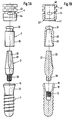
- the example further relates to taking an impression on an implant 1 inserted in the patient's mouth - here a dental implant as a full screw.
- the implant 1 has an implant head 10 which widens conically upwards and an implant shoulder 11 which narrows conically upwards.
- a mounting part - here a conical solid mounting part 2 - is screwed with its threaded part 20 into the internally threaded bore 12 of the implant 1 .
- the implant shoulder 11 outstanding pillar 21 of the conical solid body section 2 has externally a plurality of vertically extending grooves 22.
- the parts are known per se.
- a slide sleeve 3 is used to take the impression, which is divided into a sleeve piece 30 which is open at the bottom and a closed end piece 31 which closes at the top.
- the cylindrical sleeve piece 30 is smooth on the outside, while it has an inner contour 32 which is complementary to the pillar 21 and can be pushed onto it.
- the impression cap 4 is in principle cylindrical and open on both sides.
- the through-channel 40 running through the impression cap 4 is complementary to the outer shape of the sleeve piece 30 , so that the impression cap 4 can be slid over the slide sleeve 3 .
- the impression cap 4 has a cap shoulder 41 which is complementary to the implant shoulder 11 .
- the cap shoulder 41 runs around an inward-facing, elastic snap element 42 .
- the impression cap 4 is furrowed radially on the outer circumference, so that a plurality of retention plates 43 are created. Openings 44 in the impression cap 4 can be used for the escape of air and for the penetration or introduction of impression material.
- the retention plates 43 have the function of anchoring in the impression compound in order to avoid the displacement or twisting of the impression cap 4 .
- the sliding sleeve 3 pushed onto the pillar 21 with the sleeve piece 30 extends almost to the implant shoulder 11 .
- the impression cap 4 receives the sleeve piece 30 in its passage 40 , the end piece 31 protruding from the impression cap 4 at the top.
- the inner contour 32 of the slide sleeve 3 nestles against the outer contour of the pillar 21 .
- the lower outlet of the sleeve piece 30 acts as a jamming wedge between the pillar 21 and the impression cap 4 .
- the cap shoulder 41 sits practically seamless and under spring tension on the implant shoulder 11 , the snap element 42 encompassing the implant shoulder 11 in the downward direction towards the implant head 10 and virtually pulling the impression cap 4 onto the implant 1 .
- This drawing sequence is part of the production of the master model after the impression of the mouth situation has been obtained.
- the slide sleeve 3 and impression cap 4 described above are again present, which remain embedded in the impression.
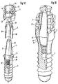
- a manipulation implant 5 - here with a solid, conical pillar 51 - and a manipulation shoulder sleeve 6 are added.
- the manipulation implant 5 has an extension 50 at the bottom and a pillar 51 identical to the pillar 21 at the top.
- the manipulation implant 5 has a fixing plate 53 with a plate shoulder 54 above the extension 50 with a plurality of retention plates 52 .
- the cylindrical, hollow manipulating shoulder sleeve 6 has a radially circumferential, elastic, inwardly curved locking edge 60 at the bottom.
- the manipulation shoulder sleeve 6 closes at the top with a manipulation shoulder 61 which is identical to the implant shoulder 11 .
- extending expansion slots 62 are provided to the locking edge 60 to increase the elasticity.
- the manipulation shoulder sleeve 6 is pushed onto the manipulation implant 5 to such an extent that the latching edge 60 encompasses the fixing plate 53 , while the snap element 42 of the impression cap 4 elastically encompasses the manipulation shoulder 61 .
- the slide sleeve 3 continues to wedge in the impression cap 4th
- a conical structural part 102 with an internal thread 123 is shown here instead of the solid conical structural component 2 .
- the threaded part 120 engages in the internally threaded bore 12 of the implant 1 .
- the conical pillar 121 with the grooves 122 and, for example, a taper of 6 ° has a different outer geometry; Accordingly, an adapted slide sleeve 103 with an inner contour 132 complementary to the pillar 121 is provided. At the bottom, the sleeve piece 130 has an inner contour with a 6 ° taper; which then changes into an 8 ° taper.
- the snap element 42 engages again the implant shoulder 11 and the lower spur of the sleeve element 130 pushes wedge-shaped clamping between the pillar 121 and the impression cap. 4
- the end piece 131 of the slide sleeve 103 protrudes from the impression cap 4 at the top.
- the manipulation implant to be used here should have a pillar identical to pillar 121 .
- a modified cone component 202 is in use; this has, for example, a taper of 8 ° on the pillar 221 .
- the slide sleeve 103 can also be used here.
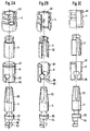
- a polygonal structural part 302 is now screwed with its threaded part 320 into the internally threaded bore 12 of the implant 1 .
- the multi-edged pillars 321 - here with an external octagon - protrudes beyond the implant shoulder 11, while the abutment 321 radially encircling, horizontal abutment shoulder 324 about - depending on tolerances - terminates with the upper edge of the implant shoulder.
- a blind hole-shaped internal threaded bore 323 extends axially into the polygonal structural part 302 .
- the lower extension of the sleeve piece 330 rests on the pillar shoulder 324 and the end piece 331 protrudes again out of the impression cap 4 at the top.
- the snap element 42 of the impression cap 4 engages around the implant shoulder 11 .
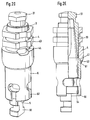
- FIG. 5A This sequence of figures outlines the work sequence from taking the impression - using the example of a solid cone component 2 - to the finished master model.
- the oral situation (FIG. 5A) is given with an implant 1 seated in the jawbone and a solid conical component 2 screwed into it.
- the slide sleeve 3 is first pushed onto the conical solid construction part 2 (FIG. 5B).
- the impression cap 4 is pushed on (FIG. 5C).
- the sequence between pushing on the slide sleeve 3 and the impression cap 4 could also be done in reverse order.
- the impression spoon 70 filled with impression material 7 is pressed onto the implant 1 equipped so far against the jawbone (FIG. 5D).
- the impression cap 4 and the slide sleeve 3 remain embedded in the impression compound 7 , and the impression AD is obtained (FIG. 5E).
- FIG. 6A This sequence of figures outlines the work sequence using the example of an angled cone mounting part 402 with an internal thread 423 , the threaded part 420 being screwed into the internal thread bore 12 in the implant 1 ; this is the mouth situation (Fig. 6A).
- An impression cylinder 8 is screwed into the internal thread 423 (FIG. 6B) and a laterally open impression cap 4 is pushed onto it, which claws against the implant shoulder 11 (FIG. 6C).
- the impression AD is taken (FIG. 6D), which is obtained after the impression tray 70 has been pulled off, in which the impression cap 4 and a cavity according to the impression cylinder 8 and the cone mounting part 402 now remain (FIG 6E).
Landscapes
- Health & Medical Sciences (AREA)
- Oral & Maxillofacial Surgery (AREA)
- Dentistry (AREA)
- Epidemiology (AREA)
- Life Sciences & Earth Sciences (AREA)
- Animal Behavior & Ethology (AREA)
- General Health & Medical Sciences (AREA)
- Public Health (AREA)
- Veterinary Medicine (AREA)
- Orthopedic Medicine & Surgery (AREA)
- Dental Prosthetics (AREA)
- Prostheses (AREA)
Description
- Figur 1A:
- ein Vollschraubenimplantat mit einem Konus-Massivaufbauteil, eine Schieberhülse und die Abdruckkappe in der Explosivdarstellung;
- Figur 1B:
- die Darstellung gemäss Figur 1A im Vertikalschnitt;
- Figur 1C:
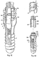
- die Darstellung gemäss Figur 1A mit eingeschraubtem Konus-Massivaufbauteil im Teilschnitt;
- Figur 1D:
- die Elemente gemäss Figur 1A im zusammengefügten Zustand als Teilschnitt;
- Figur 1E:
- die Darstellung gemäss Figur 1D in einem anderen Teilschnitt;
- Figur 1F:
- die Darstellung gemäss Figur 1E als Schnitt auf der Linie A-A;
- Figur 1G:
- als Detail den Bereich mit dem um die Implantatschulter greifenden Schnappelement im Teilschnitt;
- Figur 2A:
- ein Manipulierimplantat mit Konus-Massivteil, eine Manipulierschulterhülse, eine Schieberhülse und die Abdruckkappe in der Explosivdarstellung;
- Figur 2B:
- die Darstellung gemäss Figur 2A im vertikalen Teilschnitt;
- Figur 2C:
- die Darstellung gemäss Figur 2B in einem anderen vertikalen Teilschnitt;
- Figur 2D:
- die Elemente gemäss Figur 2A im zusammengefügten Zustand;
- Figur 2E:
- die Darstellung gemäss Figur 2D im vertikalen Teilschnitt;
- Figur 3A:
- ein Vollschraubenimplantat mit einem Konus-Aufbauteil (6°) mit Innengewinde, eine Schieberhülse und die Abdruckkappe in der Explosivdarstellung;
- Figur 3B:
- die Elemente gemäss Figur 3A im zusammengefügten Zustand, im vertikalen Teilschnitt;
- Figur 3C:
- die Darstellung gemäss Figur 3B mit einem Konus-Aufbauteil (8°);
- Figur 4A:
- ein Vollschraubenimplantat mit einem VielkantAufbauteil, eine Schieberhülse und die Abdruckkappe als Explosivdarstellung im vertikalen Teilschnitt;
- Figur 4B:
- die Elemente gemäss Figur 4A im zusammengefügten Zustand, im vertikalen Teilschnitt;
- Figur 4C:
- die Darstellung gemäss Figur 4B in einem anderen vertikalen Teilschnitt;
- Figur 4D:
- die Darstellung gemäss Figur 4C als Schnitt auf der Linie B-B;
- Figur 5A:
- Mundsituation mit im Kieferknochen sitzenden Vollschraubenimplantat und eingesetztem Konus-Massivaufbauteil;
- Figur 5B:
- die Darstellung gemäss Figur 5A mit aufgeschobener Schieberhülse;
- Figur 5C:
- die Darstellung gemäss Figur 5B mit aufgeschobener Abdruckkappe;
- Figur 5D:
- die Darstellung gemäss Figur 5C mit aufgesetztem Abdrucklöffel;
- Figur 5E:
- der gemäss Figur 5D gewonnene Abdruck;
- Figur 5F:
- das an den Abdruck gemäss Figur 5E angesetzte Konus-Massivaufbauteil;
- Figur 5G:
- die Darstellung gemäss Figur 5F mit angesetzter Manipulierschulterhülse;
- Figur 5H:
- die Darstellung gemäss Figur 5G mit abgezogenem Abdrucklöffel;
- Figur 6A:
- die Darstellung gemäss Figur 5A mit abgewinkeltem Konus-Aufbauteil;
- Figur 6B:
- die Darstellung gemäss Figur 6A mit aufgeschraubtem Abformzylinder;
- Figur 6C:
- die Darstellung gemäss Figur 6B mit aufgeschobener, lateral offener Abdruckkappe;
- Figur 6D:
- die Darstellung gemäss Figur 6C mit aufgesetztem Abdrucklöffel;
- Figur 6E:
- den Abdruck gemäss Figur 6D;
- Figur 6F:
- die Darstellung gemäss Figur 6E mit angesetzter Manipulierschulterhülse;
- Figur 6G:
- die Darstellung gemäss Figur 6F mit aufgefüllter Abdruckkappe und
- Figur 6H:
- die Darstellung gemäss Figur 6G als fertiges Meistermodell.
- Die Schieberhülse 3 kann gänzlich entfallen, wenn man den in der Abdruckkappe 4 verbliebenen Hohlraum, den der ausgewählte Pfeiler - z.B. 21 - innerhalb der Abdruckkappe 4 belässt, mit Abdruckmasse füllt. Das Einbringen der Abdruckmasse könnte durch die Durchbrüche 44 geschehen.
- Fertigungstechnisch kann es vorteilhaft sein, die Schieberhülse 3 und die Abdruckkappe 4 zu vereinen und einteilig zu gestalten.
- Es ist praktizierbar, das Manipulierimplantat 5 und die Manipulierschulterhülse 6 zu vereinen und einteilig zu gestalten.
- Die bisherige in der Beschreibung gemachte Aufzählung von Pfeilern 21,131,221,321,421 ist keinesfalls abschliessend. Auch darüber hinausgehende Pfeilerformen gelten als einbezogen.
- Die Manipulierschulterhülse 6 kann, wie die Abdruckkappe 4, am äusseren Umfang durch radiale Einfurchung erzeugte Retentionsteller und/oder radial gerichtete Durchbrüche aufweisen.
- Das Manipulierimplantat 5 und/oder die Manupulierschulterhülse 6 können gänzlich entfallen, wenn man den im Abdruck AD verbliebenen Hohlraum mit Modellmaterial auffüllt.
- Der Erfindungsgedanke lässt sich dahin generalisieren, dass die an der Abdruckkappe 4 vorgesehenen Schnappelemente 42 allgemein eine Eingriffsgeometrie haben können, welche in die am nach aussen gerichteten Implantatende, an seiner Aussenseite vorhandene, hinterschnittene Kontur, eingreifen. Die Kontur kann durch eine Trompetenform des Implantatendes oder durch eine eingearbeitete Hinterschneidung geschaffen werden.
Claims (13)
- Abdrucksystem mit einer Abdruckkappe (4) zur Übertragung eines aus einer menschlichen Gewebestruktur austretenden Abschlusses eines in den Humankörper eingesetzten Implantats (1), inklusive möglicher Aufbauten - nachstehend als Situation (S) bezeichnet -, auf ein Meistermodell (MM), wobeia) das nach aussen gerichtete Implantatende an seiner Aussenseite eine hinterschnittene Kontur aufweist, dadurch gekennzeichnet, dassb) die Abdruckkappe (4) eine zur hinterschnittenen Kontur komplementäre, darin eingreifende Geometrie aufweist.
- Abdrucksystem nach Anspruch 1, dadurch gekennzeichnet, dass die hinterschnittene Kontur entweder durch eine zum Implantatlager hin sich trompetenförmig verjüngende Implantatgeometrie oder durch eine Aussparung, nahe dem Implantatabschluss, gebildet wird.
- Abdrucksystem nach Anspruch 1 oder 2, dadurch gekennzeichnet , dass die an der Abdruckkappe (4) vorgesehene, eingreifende Geometrie ein Schnappelement (42) in Form einer zirkulären Lippe oder von einzelnen Greiforganen darstellt.
- Abdrucksystem nach Anspruch 2, dadurch gekennzeichnet, dass der trompetenförmige Implantatabschluss im Bereich des grössten Durchmessers eine abgewinkelte Schulterpartie - die Implantatschulter (11) - aufweist, auf welcher sich die an der Abdruckkappe (4) vorgesehene Kappenschulter (41) zumindest partiell abstützt.
- Abdrucksystem nach Anspruch 1, dadurch gekennzeichnet, dass die Abdruckkappe (4) am äusseren Umfang durch radiale Einfurchung erzeugte Retentionsteller (43) und/oder radial gerichtete Durchbrüche (44) aufweisen kann.
- Abdrucksystem nach Anspruch 1, dadurch gekennzeichnet, dass die Abdruckkappe (4) auf einer Seite geschlossen ist oder einen axialen Durchgangskanal (40) aufweist.
- Abdrucksystem nach Anspruch 6, dadurch gekennzeichnet, dass der Durchgangskanal (40) der Abdruckkappe (4) frei bleibt oder darin ein Pfeiler (21, 121,221,321) und/oder eine Schieberhülse (3,103,303) eingesetzt wird.
- Abdrucksystem nach Anspruch 7, dadurch gekennzeichnet, dass die Schieberhülse (3,103,303) eine zum Pfeiler (21,121,221,321) komplementäre Innenkontur (32,132, 332) besitzt und zumindest der untere Ausläufer des Hülsenstücks (30,130,330) der Schieberhülse (3,103,303) zwischen dem Pfeiler (21,121,221,321) und der Innenwandung der auf der Implantatschulter (11) ruhenden Abdruckkappe (4) sitzt.
- Abdrucksystem nach Anspruch 1, dadurch gekennzeichnet, dass für die Übertragung des von der Situation (S) gewonnenen Abdrucks (AD) auf ein Meistermodell (MM) zu dieser Situation (S) analoge, vorgefertigte Teile vorgesehen sind.
- Abdrucksystem nach Anspruch 4, dadurch gekennzeichnet, dass die Implantatschulter (11) durch eine Manipulierschulterhülse (6) mit einer oben gelegenen Manipulierschulter (61) und mit einem Haltemechanismus - möglicherweise in Form einer Rastkante (60) - verkörpert wird, wobei die Manipulierschulter (61) von dem Schnappelement (42) der Abdruckkappe (4) umfasst wird.
- Abdrucksystem nach Anspruch 1, dadurch gekennzeichnet, dass für die Übertragung des von der Situation (S) gewonnenen Abdrucks (AD) auf ein Meistermodell (MM) ein in die im gewonnenen Abdruck (AD) verbliebene Abdruckkappe (4) und Schieberhülse (3,103,303) einschiebbarer Pfeiler (51) eines Manipulierimplantats (5) vorgesehen ist, welcher in seiner äusseren Kontur formidentisch zu dem in der Situation (S) real verwendeten Pfeiler (21,121,221,321) ist.
- Abdrucksystem nach Anspruch 11, dadurch gekennzeichnet, dass am Manipulierimplantat (5) unterhalb des Pfeilers (51) ein Fortsatz (50) mit Retentionstellern (52) und einem zum Haltemechanismus (60) komplementären Fixierorgan (53) angeordnet ist.
- Abdrucksystem nach Anspruch 12, dadurch gekennzeichnet, dass der Haltemechanismus (60) der Manipulierschulterhülse (6) mit dem Fixierorgan (53) des Manipulierimplantats (5) zusammenwirkt.
Applications Claiming Priority (4)
| Application Number | Priority Date | Filing Date | Title |
|---|---|---|---|
| CH32696 | 1996-02-08 | ||
| CH326/96 | 1996-02-08 | ||
| CH32696 | 1996-02-08 | ||
| PCT/CH1997/000031 WO1997028755A1 (de) | 1996-02-08 | 1997-01-31 | Abdrucksystem für einen aus der menschlichen gewebestruktur austretenden implantatabschluss |
Publications (2)
| Publication Number | Publication Date |
|---|---|
| EP0879024A1 EP0879024A1 (de) | 1998-11-25 |
| EP0879024B1 true EP0879024B1 (de) | 1999-09-29 |
Family
ID=4184473
Family Applications (1)
| Application Number | Title | Priority Date | Filing Date |
|---|---|---|---|
| EP97900923A Expired - Lifetime EP0879024B1 (de) | 1996-02-08 | 1997-01-31 | Abdrucksystem für einen aus der menschlichen gewebestruktur austretenden implantatabschluss |
Country Status (16)
| Country | Link |
|---|---|
| US (1) | US6068478A (de) |
| EP (1) | EP0879024B1 (de) |
| JP (1) | JP3290995B2 (de) |
| KR (1) | KR100453761B1 (de) |
| AR (1) | AR005757A1 (de) |
| AT (1) | ATE185060T1 (de) |
| AU (1) | AU708386B2 (de) |
| BR (1) | BR9706645A (de) |
| CA (1) | CA2230615C (de) |
| DE (1) | DE59700503D1 (de) |
| DK (1) | DK0879024T3 (de) |
| ES (1) | ES2137046T3 (de) |
| ID (1) | ID15902A (de) |
| IL (1) | IL123396A0 (de) |
| TW (1) | TW332774B (de) |
| WO (1) | WO1997028755A1 (de) |
Cited By (8)
| Publication number | Priority date | Publication date | Assignee | Title |
|---|---|---|---|---|
| EP1252866A1 (de) | 2001-04-27 | 2002-10-30 | Straumann Holding AG | Anordnung für das Handling eines Implantats |
| USD582041S1 (en) | 2006-04-27 | 2008-12-02 | Zimmer Dental, Inc. | Impression coping |
| WO2009009910A1 (de) | 2007-07-16 | 2009-01-22 | Dentalpoint Ag | Zahnimplantat |
| DE102004053434B4 (de) * | 2004-11-05 | 2010-01-28 | Markus Dold | Implantatsystem |
| US8007279B2 (en) | 2005-06-17 | 2011-08-30 | Zimmer Dental, Inc. | Dental restorative system and components |
| WO2012101135A1 (de) | 2011-01-25 | 2012-08-02 | Dentalpoint Ag | Zahnersatz-system |
| US8430668B2 (en) | 2005-06-17 | 2013-04-30 | Zimmer Dental, Inc. | Dental restorative system and components |
| US8506296B2 (en) | 2005-06-17 | 2013-08-13 | Zimmer Dental, Inc. | Dental restorative system and components |
Families Citing this family (84)
| Publication number | Priority date | Publication date | Assignee | Title |
|---|---|---|---|---|
| US5904483A (en) | 1995-11-17 | 1999-05-18 | Wade; Curtis K. | Dental implant systems and methods |
| BR9809079A (pt) * | 1997-04-09 | 2002-01-15 | Implant Innovations Inc | Sistema de entrega de implante |
| US6203323B1 (en) | 1998-04-08 | 2001-03-20 | Implant Innovations, Inc. | Implant delivery system |
| US6619958B2 (en) | 1997-04-09 | 2003-09-16 | Implant Innovations, Inc. | Implant delivery system |
| DE69834115T2 (de) * | 1997-07-25 | 2006-10-26 | Nobel Biocare Ab (Publ) | Abdruckkappensystem für knochenintegrierte implantate |
| US6217331B1 (en) | 1997-10-03 | 2001-04-17 | Implant Innovations, Inc. | Single-stage implant system |
| EP1649825A3 (de) * | 1997-10-03 | 2006-06-07 | Implant Innovations, Inc. | Einstufiges Implantatsystem |
| US6540514B1 (en) | 1998-02-26 | 2003-04-01 | Theodore S. Falk | Method for isolating a dental implant |
| US6159010A (en) * | 1998-04-23 | 2000-12-12 | Implant Innovations, Inc. | Fenestrated dental coping |
| GB9811869D0 (en) | 1998-06-02 | 1998-07-29 | Osteo Ti Limited | A method for making a model for a dental prosthesis for mounting in an implant & a dental formation mounting arrangement |
| US6758672B2 (en) * | 2000-01-18 | 2004-07-06 | Implant Innovations, Inc. | Preparation coping for creating an accurate permanent post to support a final prosthesis and method for creating the same |
| US6382977B1 (en) | 2000-03-02 | 2002-05-07 | Nobel Biocare Usa, Inc. | Snap-in impression coping |
| DE10019332B4 (de) * | 2000-04-19 | 2005-08-25 | Heraeus Kulzer Gmbh | Pfostenförmiges Element |
| USD441448S1 (en) | 2000-05-08 | 2001-05-01 | Nobel Biocare Usa, Inc | Snap-in impression coping |
| FR2808992B1 (fr) * | 2000-05-17 | 2002-08-30 | Jean Claude Yeung | Analogue de laboratoire pour prothese dentaire |
| US6769913B2 (en) | 2000-08-30 | 2004-08-03 | Nobel Biocare Ab | Impression cap |
| US6592370B2 (en) * | 2000-09-14 | 2003-07-15 | Diro, Inc. | Abutment for dental implant and associated components for use therewith |
| FR2811883B1 (fr) * | 2001-03-07 | 2005-04-08 | Gilbert Ouaknine | Piece de transfert pour implantologie dentaire |
| US7059856B2 (en) * | 2001-08-31 | 2006-06-13 | Leonard Marotta | Stable dental analog |
| US7887327B2 (en) * | 2001-08-31 | 2011-02-15 | Leonard Marotta | Accurate analogs for prostheses using computer generated anatomical models |
| US8790408B2 (en) | 2001-08-31 | 2014-07-29 | Leonard Marotta | Accurate analogs for bone graft prostheses using computer generated anatomical models |
| US6824386B2 (en) * | 2001-11-01 | 2004-11-30 | Astra Tech Ab | Components for improved impression making |
| USD469535S1 (en) | 2001-11-01 | 2003-01-28 | Astra Tech Ab | Abutment for dental implant |
| US6951460B2 (en) * | 2001-11-01 | 2005-10-04 | Astra Tech Ab | Components and method for improved impression making |
| DE10159683A1 (de) * | 2001-11-30 | 2003-06-18 | Michael Gahlert | Dantalimplantat |
| AU2002357086A1 (en) * | 2001-12-07 | 2003-06-23 | Nobel Biocare Ab | Healing abutment |
| US7204692B2 (en) * | 2002-03-13 | 2007-04-17 | Lifecore Biomedical, Inc. | Impression cap |
| US7163398B2 (en) * | 2002-03-13 | 2007-01-16 | Lifecore Biomedical, Inc. | Impression cap |
| US20050101961A1 (en) * | 2003-11-12 | 2005-05-12 | Huebner Randall J. | Bone screws |
| US7066736B2 (en) | 2002-09-12 | 2006-06-27 | Zimmer Dental, Inc. | Dental impression coping with retention |
| IL158789A (en) | 2002-11-13 | 2009-11-18 | Biomet 3I Llc | Dental implant system |
| AU2003300196B2 (en) * | 2003-01-03 | 2009-03-12 | Nobel Biocare Services Ag | Dental implant system |
| ES2274172T3 (es) * | 2003-02-05 | 2007-05-16 | Straumann Holding Ag | Pieza de prolongacion para un implante dental, ayuda de transferencia y procedimiento para establecer una base para un elemento de retencion. |
| KR100564096B1 (ko) * | 2003-04-22 | 2006-03-24 | 이성복 | 치과용 핀 임플란트 |
| US20060003290A1 (en) * | 2004-07-01 | 2006-01-05 | Niznick Gerald A | Endosseous one-piece screw-type dental implants |
| US7632096B2 (en) * | 2004-10-18 | 2009-12-15 | Gittleman Neal B | Rotating winged low profile impression transfer cap |
| DE102005005402B4 (de) * | 2005-02-05 | 2011-02-17 | Friadent Gmbh | Dentalimplantat sowie Implantatsystem |
| US20060199150A1 (en) * | 2005-03-07 | 2006-09-07 | Niznick Gerald A | Externally-threaded, one-piece endosseous dental implant with angled abutment |
| US20080008981A1 (en) * | 2005-03-21 | 2008-01-10 | Friadent Gmbh | Abutment set for a dental implant |
| KR100646771B1 (ko) * | 2005-05-09 | 2006-11-23 | 김만용 | 치과용 임플란트 장치 및 이에 사용되는 보정장치 |
| EP1985256A1 (de) | 2006-02-16 | 2008-10-29 | Francisco Javier Garcia Saban | Zahnimplantatanordnung und vorrichtung zur vornahme eines zahnabdrucks |
| CA2670224C (en) * | 2006-11-22 | 2014-07-22 | Philippe Dacremont | Supraosseous dental implant |
| JP4321637B2 (ja) * | 2007-07-27 | 2009-08-26 | セイコーエプソン株式会社 | 歯科用インプラントの製造方法 |
| JP4321636B2 (ja) | 2007-07-27 | 2009-08-26 | セイコーエプソン株式会社 | 歯科用インプラントの製造方法 |
| JP4321635B2 (ja) * | 2007-07-27 | 2009-08-26 | セイコーエプソン株式会社 | 歯科用インプラントの製造方法 |
| US7632095B2 (en) | 2007-08-13 | 2009-12-15 | Biomet 3I, Inc. | Method for forming a dental prosthesis |
| ITNA20070102A1 (it) * | 2007-10-18 | 2009-04-19 | Pio Donnarumma | Dispositivo medicale odontoiatrico (moncone scomponibile)per la realizzazione di impronte e successiva costruzione di manufatti implanto-protesici con connessione amovibile e personalizzabile per qualunque tipologia d'impianti. |
| WO2009137545A1 (en) * | 2008-05-06 | 2009-11-12 | Keystone Dental, Inc. | Coping-analogue kit |
| US20090298014A1 (en) * | 2008-05-28 | 2009-12-03 | Global Implant Solutions, Llc | Dental Implant |
| EP2130513A1 (de) * | 2008-06-06 | 2009-12-09 | Straumann Holding AG | Vorrichtung zum Anbringen einer Abformkappe an einem Zahnimplantat |
| US20100015571A1 (en) * | 2008-07-15 | 2010-01-21 | Global Implant Solutions, Llc | Flexible Abutment For Use With A Dental Implant |
| US20100112521A1 (en) * | 2008-11-02 | 2010-05-06 | Timothy Dow Chapel | Dental abutment analog for implant-secured restoration |
| RU2391938C1 (ru) * | 2008-12-04 | 2010-06-20 | Вадим Александрович Луганский | Способ переноса позиции имплантата с оттиска на гипсовую модель |
| US20100151420A1 (en) * | 2008-12-11 | 2010-06-17 | Ranck Roger S | Fixtures for dental implants |
| US20100151423A1 (en) * | 2008-12-11 | 2010-06-17 | Ranck Roger S | Temporary restorations and related methods |
| US20100209877A1 (en) | 2009-02-13 | 2010-08-19 | Stephen Hogan | Components for use with implants and related methods |
| US20100159417A1 (en) * | 2008-12-18 | 2010-06-24 | Dale Whipple | Dental impression cap with engagement feature |
| WO2010075993A1 (de) * | 2009-01-02 | 2010-07-08 | Robert Laux | Abdruckkappe mit abdruckpfosten für ein zahnimplantat |
| US8075313B2 (en) * | 2009-01-19 | 2011-12-13 | Aeton Medical Llc | Transfer copings and related methods for taking implant impressions |
| US8827704B2 (en) * | 2009-02-04 | 2014-09-09 | Mid Corp | System, method and apparatus for implementing dental implants |
| KR100948074B1 (ko) * | 2009-03-23 | 2010-03-16 | 주식회사 이노바이오써지 | 임플란트 보철 부품세트 및 상기 부품세트를 이용하여 지대주가 포함된 복제 석고모델의 제작방법 |
| RU2425652C2 (ru) * | 2009-05-22 | 2011-08-10 | Елена Владимировна Мамчиц | Способ фиксации зубных протезов на имплантатах |
| US20110086327A1 (en) * | 2009-10-09 | 2011-04-14 | Sheldon Lerner | Combination UCLA Impression Coping and Installation Procedure |
| US20130260339A1 (en) * | 2009-11-17 | 2013-10-03 | Uab Research Foundation | High torque dental implant system |
| US20110229850A1 (en) * | 2010-03-18 | 2011-09-22 | Bretton Joseph N | Dental coping and assembly with aligning anti-rotation feature |
| ES2566758T3 (es) | 2010-03-25 | 2016-04-15 | Straumann Holding Ag | Cofia de impresión para un implante dental |
| BR112013019637A2 (pt) | 2011-02-02 | 2018-07-17 | Mid Corp | sistemas, aparelho e métodos para implantação de implantes |
| WO2012115969A2 (en) | 2011-02-21 | 2012-08-30 | Aeton Medical Llc | Abutment and abutment systems for use with implants |
| US9925024B2 (en) | 2011-06-28 | 2018-03-27 | Biomet 3I, Llc | Dental implant and abutment tools |
| US8827702B2 (en) * | 2011-09-12 | 2014-09-09 | Cortex Dental Implant Industries, Ltd. | Driver and method |
| US9381112B1 (en) | 2011-10-06 | 2016-07-05 | William Eric Sponsell | Bleb drainage device, ophthalmological product and methods |
| DE202011052393U1 (de) | 2011-12-21 | 2012-01-10 | Bredent Medical Gmbh & Co. Kg | Zahnprothetisches Abutment und Klebebasis hierfür |
| US8632489B1 (en) | 2011-12-22 | 2014-01-21 | A. Mateen Ahmed | Implantable medical assembly and methods |
| GB201212125D0 (en) | 2012-07-09 | 2012-08-22 | Nobel Biocare Services Ag | Abutment system and dental methods |
| DE102013004175B4 (de) * | 2013-03-12 | 2017-01-26 | Bruno Spindler | Implantatanalog und Analoglagerkörper |
| WO2014195955A1 (en) * | 2013-06-06 | 2014-12-11 | Honig Iulian | Dental implant device, system and method of use |
| US9861455B2 (en) | 2013-07-30 | 2018-01-09 | TI Intellectual Property Inc. | Dental implant system |
| WO2015030289A1 (ko) * | 2013-08-28 | 2015-03-05 | 라파바이오 주식회사 | 힐링 어버트먼트와 그에 체결이 가능한 임프레션 캡을 이용한 치아보철물 제조방법 |
| CN103976800B (zh) * | 2014-04-16 | 2016-05-04 | 玄龙培 | 种植牙手术用印模辅助帽及印模方法 |
| ES2884974T3 (es) | 2017-03-20 | 2021-12-13 | Straumann Holding Ag | Análogo de implante |
| US11311354B2 (en) | 2018-10-09 | 2022-04-26 | Smart Denture Conversions, Llc | Screw-attached pick-up dental coping system and methods |
| KR102357622B1 (ko) * | 2021-05-21 | 2022-02-08 | 장현성 | 치과용 솔리드 어버트먼트 |
| US11957538B2 (en) | 2021-12-23 | 2024-04-16 | Smart Denture Conversions, Llc | Screw-attached pick-up dental coping system, methods and accessories |
| CA224683S (en) * | 2023-02-20 | 2025-06-05 | Straumann Inst Ag | Dental abutment |
Family Cites Families (1)
| Publication number | Priority date | Publication date | Assignee | Title |
|---|---|---|---|---|
| DE4415670A1 (de) * | 1994-05-04 | 1995-11-09 | Degussa | Abformkappe für Dentalimplantate |
-
1997
- 1997-01-31 DE DE59700503T patent/DE59700503D1/de not_active Expired - Lifetime
- 1997-01-31 AT AT97900923T patent/ATE185060T1/de active
- 1997-01-31 IL IL12339697A patent/IL123396A0/xx not_active IP Right Cessation
- 1997-01-31 TW TW086101108A patent/TW332774B/zh not_active IP Right Cessation
- 1997-01-31 ES ES97900923T patent/ES2137046T3/es not_active Expired - Lifetime
- 1997-01-31 EP EP97900923A patent/EP0879024B1/de not_active Expired - Lifetime
- 1997-01-31 CA CA002230615A patent/CA2230615C/en not_active Expired - Lifetime
- 1997-01-31 JP JP52801797A patent/JP3290995B2/ja not_active Expired - Lifetime
- 1997-01-31 BR BR9706645A patent/BR9706645A/pt not_active IP Right Cessation
- 1997-01-31 KR KR10-1998-0702621A patent/KR100453761B1/ko not_active Expired - Fee Related
- 1997-01-31 US US09/066,321 patent/US6068478A/en not_active Expired - Lifetime
- 1997-01-31 WO PCT/CH1997/000031 patent/WO1997028755A1/de not_active Ceased
- 1997-01-31 AU AU14354/97A patent/AU708386B2/en not_active Expired
- 1997-01-31 DK DK97900923T patent/DK0879024T3/da active
- 1997-02-07 AR ARP970100502A patent/AR005757A1/es active IP Right Grant
- 1997-02-07 ID IDP970388A patent/ID15902A/id unknown
Cited By (10)
| Publication number | Priority date | Publication date | Assignee | Title |
|---|---|---|---|---|
| EP1252866A1 (de) | 2001-04-27 | 2002-10-30 | Straumann Holding AG | Anordnung für das Handling eines Implantats |
| WO2002087461A1 (de) | 2001-04-27 | 2002-11-07 | Straumann Holding Ag | Anordnung für das handling eines implantats |
| DE102004053434B4 (de) * | 2004-11-05 | 2010-01-28 | Markus Dold | Implantatsystem |
| US8007279B2 (en) | 2005-06-17 | 2011-08-30 | Zimmer Dental, Inc. | Dental restorative system and components |
| US8430668B2 (en) | 2005-06-17 | 2013-04-30 | Zimmer Dental, Inc. | Dental restorative system and components |
| US8506296B2 (en) | 2005-06-17 | 2013-08-13 | Zimmer Dental, Inc. | Dental restorative system and components |
| US9125710B2 (en) | 2005-06-17 | 2015-09-08 | Zimmer Dental, Inc. | Dental restorative system and components |
| USD582041S1 (en) | 2006-04-27 | 2008-12-02 | Zimmer Dental, Inc. | Impression coping |
| WO2009009910A1 (de) | 2007-07-16 | 2009-01-22 | Dentalpoint Ag | Zahnimplantat |
| WO2012101135A1 (de) | 2011-01-25 | 2012-08-02 | Dentalpoint Ag | Zahnersatz-system |
Also Published As
| Publication number | Publication date |
|---|---|
| AU708386B2 (en) | 1999-08-05 |
| KR19990064140A (ko) | 1999-07-26 |
| AR005757A1 (es) | 1999-07-14 |
| DK0879024T3 (da) | 2000-03-27 |
| TW332774B (en) | 1998-06-01 |
| DE59700503D1 (de) | 1999-11-04 |
| WO1997028755A1 (de) | 1997-08-14 |
| IL123396A0 (en) | 1998-09-24 |
| ATE185060T1 (de) | 1999-10-15 |
| JPH11503655A (ja) | 1999-03-30 |
| ES2137046T3 (es) | 1999-12-01 |
| KR100453761B1 (ko) | 2004-12-17 |
| ID15902A (id) | 1997-08-14 |
| CA2230615C (en) | 2000-05-30 |
| US6068478A (en) | 2000-05-30 |
| EP0879024A1 (de) | 1998-11-25 |
| CA2230615A1 (en) | 1997-08-14 |
| BR9706645A (pt) | 1999-01-12 |
| JP3290995B2 (ja) | 2002-06-10 |
| AU1435497A (en) | 1997-08-28 |
Similar Documents
| Publication | Publication Date | Title |
|---|---|---|
| EP0879024A1 (de) | Abdrucksystem für einen aus der menschlichen gewebestruktur austretenden implantatabschluss | |
| EP0629384B1 (de) | Vorrichtung zur Befestigung eines künstlichen Zahnersatzes an einem Kieferknochen | |
| EP0986343B1 (de) | Vorrichtung zur bildung eines zahnersatzes | |
| DE69735934T2 (de) | Austrittsprofilsystem mit gemeinsamer einheil- und abdruckkappe | |
| DE69628461T2 (de) | Zahnärtzliche anordnung | |
| DE69832794T2 (de) | Zahn implantatsysteme | |
| DE60224942T2 (de) | Komponenten und verfahren für die verbesserte herstellung von abdrücken | |
| EP0801544B1 (de) | Verbindungsanordnung zwischen einem implantat und einem abutment | |
| DE3421056C2 (de) | Kieferimplantat mit einem Tragabschnitte aufweisenden Unterteil | |
| DE69520399T2 (de) | Zahnärztliche Restaurationsstruktur | |
| EP0814724B1 (de) | Verbindungsanordnung eines dentalimplantats mit einem konus-sekundärteil | |
| DE3515819C2 (de) | ||
| EP0879025B1 (de) | Abdrucksystem für implantate mit einer abdruckkappe | |
| DE2549114C3 (de) | Dentalimplantat aus Aluminiumoxid-Keramik zur Befestigung einer Suprastruktur | |
| DE69923685T2 (de) | Zahnmedizinische implantats-komponente | |
| EP0868889A1 (de) | Zahnimplantat | |
| EP2626035A1 (de) | Vorrichtungen und Verfahren zur Verbindung einer dentalen Prothesenkonstruktion mit einem Kieferknochen | |
| DE19705571A1 (de) | Kieferschraubenimplantat | |
| DE3811498A1 (de) | Dentales kieferimplantat | |
| EP1943979A1 (de) | Zahnmedizinisches Implantat und Einsatz für ein zahnmedizinisches Implantat | |
| EP0896812A1 (de) | Implantateinsatz zum Fördern des Wachstums der Gingiva | |
| DE2139683A1 (de) | Stiftzahn und seine befestigung im mund | |
| WO2015097024A1 (de) | Zahnprothetische anordnung | |
| WO1998042273A1 (de) | Zahnimplantat | |
| DE10009448A1 (de) | Aufbaupfosten und Befestigungseinrichtung zur Befestigung eines Zahn- oder Kiefersegments auf einem Basisträger |
Legal Events
| Date | Code | Title | Description |
|---|---|---|---|
| PUAI | Public reference made under article 153(3) epc to a published international application that has entered the european phase |
Free format text: ORIGINAL CODE: 0009012 |
|
| 17P | Request for examination filed |
Effective date: 19980220 |
|
| AK | Designated contracting states |
Kind code of ref document: A1 Designated state(s): AT BE CH DE DK ES FI FR GB IE IT LI LU NL PT SE |
|
| EL | Fr: translation of claims filed | ||
| GRAG | Despatch of communication of intention to grant |
Free format text: ORIGINAL CODE: EPIDOS AGRA |
|
| GRAG | Despatch of communication of intention to grant |
Free format text: ORIGINAL CODE: EPIDOS AGRA |
|
| GRAH | Despatch of communication of intention to grant a patent |
Free format text: ORIGINAL CODE: EPIDOS IGRA |
|
| 17Q | First examination report despatched |
Effective date: 19990226 |
|
| GRAH | Despatch of communication of intention to grant a patent |
Free format text: ORIGINAL CODE: EPIDOS IGRA |
|
| GRAA | (expected) grant |
Free format text: ORIGINAL CODE: 0009210 |
|
| AK | Designated contracting states |
Kind code of ref document: B1 Designated state(s): AT BE CH DE DK ES FI FR GB IE IT LI LU NL PT SE |
|
| PG25 | Lapsed in a contracting state [announced via postgrant information from national office to epo] |
Ref country code: GB Free format text: LAPSE BECAUSE OF FAILURE TO SUBMIT A TRANSLATION OF THE DESCRIPTION OR TO PAY THE FEE WITHIN THE PRESCRIBED TIME-LIMIT Effective date: 19990929 |
|
| REF | Corresponds to: |
Ref document number: 185060 Country of ref document: AT Date of ref document: 19991015 Kind code of ref document: T |
|
| REG | Reference to a national code |
Ref country code: CH Ref legal event code: EP |
|
| ITF | It: translation for a ep patent filed | ||
| REG | Reference to a national code |
Ref country code: CH Ref legal event code: NV Representative=s name: A. BRAUN, BRAUN, HERITIER, ESCHMANN AG PATENTANWAE |
|
| REF | Corresponds to: |
Ref document number: 59700503 Country of ref document: DE Date of ref document: 19991104 |
|
| REG | Reference to a national code |
Ref country code: IE Ref legal event code: FG4D Free format text: GERMAN Ref country code: ES Ref legal event code: FG2A Ref document number: 2137046 Country of ref document: ES Kind code of ref document: T3 |
|
| PG25 | Lapsed in a contracting state [announced via postgrant information from national office to epo] |
Ref country code: PT Free format text: LAPSE BECAUSE OF FAILURE TO SUBMIT A TRANSLATION OF THE DESCRIPTION OR TO PAY THE FEE WITHIN THE PRESCRIBED TIME-LIMIT Effective date: 19991229 |
|
| PG25 | Lapsed in a contracting state [announced via postgrant information from national office to epo] |
Ref country code: LU Free format text: LAPSE BECAUSE OF NON-PAYMENT OF DUE FEES Effective date: 20000131 Ref country code: BE Free format text: LAPSE BECAUSE OF NON-PAYMENT OF DUE FEES Effective date: 20000131 |
|
| ET | Fr: translation filed | ||
| REG | Reference to a national code |
Ref country code: DK Ref legal event code: T3 |
|
| GBV | Gb: ep patent (uk) treated as always having been void in accordance with gb section 77(7)/1977 [no translation filed] |
Effective date: 19990929 |
|
| PG25 | Lapsed in a contracting state [announced via postgrant information from national office to epo] |
Ref country code: IE Free format text: LAPSE BECAUSE OF NON-PAYMENT OF DUE FEES Effective date: 20000719 |
|
| PLBE | No opposition filed within time limit |
Free format text: ORIGINAL CODE: 0009261 |
|
| STAA | Information on the status of an ep patent application or granted ep patent |
Free format text: STATUS: NO OPPOSITION FILED WITHIN TIME LIMIT |
|
| BERE | Be: lapsed |
Owner name: INSTITUT STRAUMANN A.G. Effective date: 20000131 |
|
| REG | Reference to a national code |
Ref country code: IE Ref legal event code: FD4D |
|
| 26N | No opposition filed | ||
| REG | Reference to a national code |
Ref country code: CH Ref legal event code: NV Representative=s name: DR. GERHARD ULLRICH |
|
| REG | Reference to a national code |
Ref country code: CH Ref legal event code: NV Representative=s name: HEPP, WENGER & RYFFEL AG |
|
| REG | Reference to a national code |
Ref country code: CH Ref legal event code: NV Representative=s name: PATENTANWAELTE SCHAAD, BALASS, MENZL & PARTNER AG |
|
| PG25 | Lapsed in a contracting state [announced via postgrant information from national office to epo] |
Ref country code: IT Free format text: LAPSE BECAUSE OF NON-PAYMENT OF DUE FEES Effective date: 20050131 |
|
| REG | Reference to a national code |
Ref country code: CH Ref legal event code: PUE Owner name: STRAUMANN HOLDING AG Free format text: INSTITUT STRAUMANN AG#HAUPTSTRASSE 26D#4437 WALDENBURG (CH) -TRANSFER TO- STRAUMANN HOLDING AG#PETER MERIAN-WEG 12#4002 BASEL (CH) |
|
| NLS | Nl: assignments of ep-patents |
Owner name: STRAUMANN HOLDING AG Effective date: 20070205 |
|
| REG | Reference to a national code |
Ref country code: FR Ref legal event code: TP |
|
| PGRI | Patent reinstated in contracting state [announced from national office to epo] |
Ref country code: IT Effective date: 20091201 |
|
| REG | Reference to a national code |
Ref country code: FR Ref legal event code: PLFP Year of fee payment: 20 |
|
| PGFP | Annual fee paid to national office [announced via postgrant information from national office to epo] |
Ref country code: NL Payment date: 20160120 Year of fee payment: 20 |
|
| PGFP | Annual fee paid to national office [announced via postgrant information from national office to epo] |
Ref country code: CH Payment date: 20160120 Year of fee payment: 20 Ref country code: IT Payment date: 20160127 Year of fee payment: 20 Ref country code: DE Payment date: 20160120 Year of fee payment: 20 Ref country code: ES Payment date: 20160112 Year of fee payment: 20 Ref country code: DK Payment date: 20160120 Year of fee payment: 20 |
|
| PGFP | Annual fee paid to national office [announced via postgrant information from national office to epo] |
Ref country code: FI Payment date: 20160113 Year of fee payment: 20 Ref country code: SE Payment date: 20160120 Year of fee payment: 20 Ref country code: AT Payment date: 20160121 Year of fee payment: 20 Ref country code: FR Payment date: 20160121 Year of fee payment: 20 |
|
| REG | Reference to a national code |
Ref country code: DE Ref legal event code: R071 Ref document number: 59700503 Country of ref document: DE |
|
| REG | Reference to a national code |
Ref country code: NL Ref legal event code: MK Effective date: 20170130 |
|
| REG | Reference to a national code |
Ref country code: DK Ref legal event code: EUP Effective date: 20170131 |
|
| REG | Reference to a national code |
Ref country code: CH Ref legal event code: PL |
|
| REG | Reference to a national code |
Ref country code: AT Ref legal event code: MK07 Ref document number: 185060 Country of ref document: AT Kind code of ref document: T Effective date: 20170131 |
|
| REG | Reference to a national code |
Ref country code: SE Ref legal event code: EUG |
|
| REG | Reference to a national code |
Ref country code: ES Ref legal event code: FD2A Effective date: 20170526 |
|
| PG25 | Lapsed in a contracting state [announced via postgrant information from national office to epo] |
Ref country code: ES Free format text: LAPSE BECAUSE OF EXPIRATION OF PROTECTION Effective date: 20170201 |