EP0874717B1 - Backing plates for abrasive disks - Google Patents
Backing plates for abrasive disks Download PDFInfo
- Publication number
- EP0874717B1 EP0874717B1 EP96942067A EP96942067A EP0874717B1 EP 0874717 B1 EP0874717 B1 EP 0874717B1 EP 96942067 A EP96942067 A EP 96942067A EP 96942067 A EP96942067 A EP 96942067A EP 0874717 B1 EP0874717 B1 EP 0874717B1
- Authority
- EP
- European Patent Office
- Prior art keywords
- disk
- backing plate
- sanding
- apertures
- abrasive
- Prior art date
- Legal status (The legal status is an assumption and is not a legal conclusion. Google has not performed a legal analysis and makes no representation as to the accuracy of the status listed.)
- Expired - Lifetime
Links
- 239000000463 material Substances 0.000 claims description 57
- 239000003082 abrasive agent Substances 0.000 claims description 12
- 239000012858 resilient material Substances 0.000 claims description 6
- 239000004033 plastic Substances 0.000 claims description 5
- 229920003023 plastic Polymers 0.000 claims description 5
- 229920001971 elastomer Polymers 0.000 claims description 3
- 230000007246 mechanism Effects 0.000 claims description 3
- 238000001816 cooling Methods 0.000 abstract description 30
- 238000009987 spinning Methods 0.000 abstract description 19
- 230000000694 effects Effects 0.000 abstract description 17
- 238000000034 method Methods 0.000 abstract description 11
- 238000005299 abrasion Methods 0.000 abstract description 8
- 230000008569 process Effects 0.000 abstract description 6
- 238000009423 ventilation Methods 0.000 description 28
- 238000005520 cutting process Methods 0.000 description 27
- 239000007788 liquid Substances 0.000 description 13
- 230000008901 benefit Effects 0.000 description 10
- 238000004519 manufacturing process Methods 0.000 description 9
- 239000002184 metal Substances 0.000 description 8
- 229910052751 metal Inorganic materials 0.000 description 8
- 239000002699 waste material Substances 0.000 description 8
- 239000000428 dust Substances 0.000 description 7
- 238000003825 pressing Methods 0.000 description 7
- 230000009471 action Effects 0.000 description 6
- XLYOFNOQVPJJNP-UHFFFAOYSA-N water Substances O XLYOFNOQVPJJNP-UHFFFAOYSA-N 0.000 description 6
- 238000010008 shearing Methods 0.000 description 5
- 208000027418 Wounds and injury Diseases 0.000 description 4
- 230000015572 biosynthetic process Effects 0.000 description 4
- 230000006378 damage Effects 0.000 description 4
- 238000000605 extraction Methods 0.000 description 4
- 239000000835 fiber Substances 0.000 description 4
- 239000012530 fluid Substances 0.000 description 4
- 238000005755 formation reaction Methods 0.000 description 4
- 238000007373 indentation Methods 0.000 description 4
- 239000002245 particle Substances 0.000 description 4
- 239000007787 solid Substances 0.000 description 4
- 238000012360 testing method Methods 0.000 description 4
- 239000004821 Contact adhesive Substances 0.000 description 3
- 238000013461 design Methods 0.000 description 3
- 239000006260 foam Substances 0.000 description 3
- 238000000227 grinding Methods 0.000 description 3
- 210000003128 head Anatomy 0.000 description 3
- 208000014674 injury Diseases 0.000 description 3
- 230000004048 modification Effects 0.000 description 3
- 238000012986 modification Methods 0.000 description 3
- 230000002688 persistence Effects 0.000 description 3
- CURLTUGMZLYLDI-UHFFFAOYSA-N Carbon dioxide Chemical compound O=C=O CURLTUGMZLYLDI-UHFFFAOYSA-N 0.000 description 2
- XEEYBQQBJWHFJM-UHFFFAOYSA-N Iron Chemical compound [Fe] XEEYBQQBJWHFJM-UHFFFAOYSA-N 0.000 description 2
- 229910000831 Steel Inorganic materials 0.000 description 2
- 230000001464 adherent effect Effects 0.000 description 2
- 239000000853 adhesive Substances 0.000 description 2
- 230000001070 adhesive effect Effects 0.000 description 2
- 230000002411 adverse Effects 0.000 description 2
- 239000011230 binding agent Substances 0.000 description 2
- 238000010276 construction Methods 0.000 description 2
- 239000004744 fabric Substances 0.000 description 2
- 239000003292 glue Substances 0.000 description 2
- 238000007689 inspection Methods 0.000 description 2
- 238000005304 joining Methods 0.000 description 2
- 238000002844 melting Methods 0.000 description 2
- 230000008018 melting Effects 0.000 description 2
- 238000012856 packing Methods 0.000 description 2
- 229920002635 polyurethane Polymers 0.000 description 2
- 239000004814 polyurethane Substances 0.000 description 2
- 230000009467 reduction Effects 0.000 description 2
- 230000008439 repair process Effects 0.000 description 2
- 230000000717 retained effect Effects 0.000 description 2
- 239000000565 sealant Substances 0.000 description 2
- 239000010959 steel Substances 0.000 description 2
- 241000237503 Pectinidae Species 0.000 description 1
- 239000006061 abrasive grain Substances 0.000 description 1
- 230000001154 acute effect Effects 0.000 description 1
- 230000004075 alteration Effects 0.000 description 1
- 210000003484 anatomy Anatomy 0.000 description 1
- 238000010009 beating Methods 0.000 description 1
- 230000009286 beneficial effect Effects 0.000 description 1
- 229910002092 carbon dioxide Inorganic materials 0.000 description 1
- 239000001569 carbon dioxide Substances 0.000 description 1
- 238000005266 casting Methods 0.000 description 1
- 239000011248 coating agent Substances 0.000 description 1
- 238000000576 coating method Methods 0.000 description 1
- 150000001875 compounds Chemical class 0.000 description 1
- 230000006835 compression Effects 0.000 description 1
- 238000007906 compression Methods 0.000 description 1
- 238000010425 computer drawing Methods 0.000 description 1
- 230000036461 convulsion Effects 0.000 description 1
- 238000005336 cracking Methods 0.000 description 1
- 239000002173 cutting fluid Substances 0.000 description 1
- 230000001419 dependent effect Effects 0.000 description 1
- 230000006866 deterioration Effects 0.000 description 1
- 238000010586 diagram Methods 0.000 description 1
- 229910003460 diamond Inorganic materials 0.000 description 1
- 239000010432 diamond Substances 0.000 description 1
- 230000009977 dual effect Effects 0.000 description 1
- 239000000945 filler Substances 0.000 description 1
- 239000003517 fume Substances 0.000 description 1
- 230000006870 function Effects 0.000 description 1
- 239000008187 granular material Substances 0.000 description 1
- 238000010438 heat treatment Methods 0.000 description 1
- 238000009434 installation Methods 0.000 description 1
- 229910052742 iron Inorganic materials 0.000 description 1
- 230000001788 irregular Effects 0.000 description 1
- 238000003698 laser cutting Methods 0.000 description 1
- 239000000314 lubricant Substances 0.000 description 1
- 239000003550 marker Substances 0.000 description 1
- 230000013011 mating Effects 0.000 description 1
- 230000001473 noxious effect Effects 0.000 description 1
- 239000003973 paint Substances 0.000 description 1
- 238000010422 painting Methods 0.000 description 1
- 230000002093 peripheral effect Effects 0.000 description 1
- 238000002360 preparation method Methods 0.000 description 1
- 230000001737 promoting effect Effects 0.000 description 1
- 230000001681 protective effect Effects 0.000 description 1
- 230000005855 radiation Effects 0.000 description 1
- 239000002994 raw material Substances 0.000 description 1
- 210000001525 retina Anatomy 0.000 description 1
- 235000020637 scallop Nutrition 0.000 description 1
- 239000007921 spray Substances 0.000 description 1
- 238000003860 storage Methods 0.000 description 1
- 239000000126 substance Substances 0.000 description 1
- 229920002994 synthetic fiber Polymers 0.000 description 1
- 238000012546 transfer Methods 0.000 description 1
- 239000002966 varnish Substances 0.000 description 1
- 210000003462 vein Anatomy 0.000 description 1
- 230000000007 visual effect Effects 0.000 description 1
- 239000002023 wood Substances 0.000 description 1
Images


Classifications
-
- B—PERFORMING OPERATIONS; TRANSPORTING
- B24—GRINDING; POLISHING
- B24D—TOOLS FOR GRINDING, BUFFING OR SHARPENING
- B24D7/00—Bonded abrasive wheels, or wheels with inserted abrasive blocks, designed for acting otherwise than only by their periphery, e.g. by the front face; Bushings or mountings therefor
- B24D7/10—Bonded abrasive wheels, or wheels with inserted abrasive blocks, designed for acting otherwise than only by their periphery, e.g. by the front face; Bushings or mountings therefor with cooling provisions
-
- B—PERFORMING OPERATIONS; TRANSPORTING
- B24—GRINDING; POLISHING
- B24D—TOOLS FOR GRINDING, BUFFING OR SHARPENING
- B24D9/00—Wheels or drums supporting in exchangeable arrangement a layer of flexible abrasive material, e.g. sandpaper
- B24D9/08—Circular back-plates for carrying flexible material
-
- B—PERFORMING OPERATIONS; TRANSPORTING
- B24—GRINDING; POLISHING
- B24D—TOOLS FOR GRINDING, BUFFING OR SHARPENING
- B24D7/00—Bonded abrasive wheels, or wheels with inserted abrasive blocks, designed for acting otherwise than only by their periphery, e.g. by the front face; Bushings or mountings therefor
- B24D7/12—Bonded abrasive wheels, or wheels with inserted abrasive blocks, designed for acting otherwise than only by their periphery, e.g. by the front face; Bushings or mountings therefor with apertures for inspecting the surface to be abraded
Definitions
- This invention relates to the field of abrasive or sanding disks, and in particular this invention relates to backing plates for abrasive disks.
- Abrasive disks, or sanding disks are widely used on portable electric drills and (at a more professional level) on hand-held angle grinders. When used on these machines the disk is held by its centre against a backing plate and is rotated at generally a high speed while pressed in front of a backing plate against the work. The abrasive surface wears down the surface of the work by, in effect, a cutting action.
- Angle-grinder mounted sanding disks are commonly used (for example) in automotive panel beating, where body filler is to be sanded back to conform to the original contours of a remodelled car part. It is said that millions of sanding disks suitable for use with angle grinders are sold each year. There are some problems related to the use of sanding disks, such as:
- the invention is also applicable to sanding disks used in some other power tools, such as ordinary electric drills, even though the usual types of electric drills do not spin at such a high speed.
- aperture means a channel or hole passing completely through an object, and is surrounded on all sides by the material of the object. It is not limited to apertures having a circular profile. "Dished” means that a disk has been formed into a convex shape (like a saucer) and for this invention the abrasive would usually be found on the base, or convex side, of the saucer.
- Disk refers to a flat piece of relatively rigid material (though having some resilience) which is adapted for mounting on a rotatable spindle or arbor. It is not limited here to purely circular shapes and the materials used can be any of those known for use in the production of abrasive disks for rotary grinders.
- Gap means an indentation or invagination which is incompletely surrounded by the material of the object. It would include therefore configurations in which the circular periphery of a disk has had a segment, (defined below), removed or the configuration obtained by (notionally) moving an "aperture” until a portion extended beyond the periphery of the disk.
- “Sanding” is used herein to refer to any abrading or finishing operation in which the surface of a workpiece is treated to remove material or alter the roughness. "Segment” means that portion of a circle which lies between the perimeter and a chord.
- the invention is defined in claim 1. It relates to a backing plate for use as part of a sanding system for use with an angle grinder or the like, which sanding System comprises a backing plate and a "sanding" disk bearing at least one abrasive surface, the disk being adapted for mounting upon an arbor of the angle grinder in conjunction with a matching backing plate, and in which the sanding disk is modified by being provided with at least one non-concentric aperture adapted for viewing and ventilation which aperture is capable in use of being substantially in alignment with at least and in one similarly adapted viewing and ventilation gap or aperture constructed within the backing plate which is the subject-matter of the present invention, so that in use the work surface and the sanding disk are cooler as a result of air movement, abraded material is moved tangentially away, and the user can see the work through the at least one non-concentric apertures.
- non-concentric as applied to apertures in this Application means that the aperture is displaced from the axis of rotation along a radius of the disk or of the backing plate.
- a preferred number of non-concentric apertures adapted for viewing and ventilation is between one and nine.
- a more preferred number of non-concentric apertures is between three and five.
- non-concentric apertures adapted for viewing and ventilation are placed at varying distances from the centre of rotation of the disk or of the backing plate so that when the disk is rotated, a substantial proportion of the area beneath the disk can be seen.
- abrasive disk component or "sanding disk” of the sanding system is the subject of PCT/US96/19191 and is NOT part of the present invention but is described herein to assist in understanding the invention claimed herein which relates to the backing plate used in conjunction with such abrasive disks.
- the sanding disk as described previously, can be modified to provide that at least one edge of the or each non-concentric aperture adapted for viewing and ventilation is formed in order to serve as a cutting edge.
- viewing or ventilation apertures may also be regarded as means to intermittently interrupt the abrading action of the disk as it turns, thereby providing a "rest time" during which time the work surface may become cooler.
- the sanding disk may be provided with one or more apertures primarily intended for alignment with alignment features upon the backing plate, so that the sanding disk can on installation be aligned so that apertures within the sanding disk are matched with apertures within the backing plate.
- the one or more alignment apertures may also serve as engagement means to mate with drive pins extending from the backing plate.
- one or more apertures are provided in the sanding disk in positions capable of matching air extraction apertures within a backing plate.
- the perimeter of the sanding disk may be distorted from a circular shape by the provision of one or more gaps, most preferably in the form of segments, around from the circumference of the disk. Where a plurality of such gaps are provided it is preferred that they be symmetrically located to maintain balance in the disk. Preferably there are from three to eight gaps.
- the number of gaps matches the number of non-concentric apertures adapted for viewing and ventilation and are located on radii between those on which the apertures are located.
- each gap has the shape of a straight line joining one part of the circumference to another. Otherwise expressed, the gap is formed by removal of a segment of the disk. Preferably the dimensions of the or each gap are adjusted so that when the sanding disk is rotated, it is possible to see through the disk in the zone outside that of the viewing/ventilation apertures, and as far as the edge.
- this type of gap may be used advantageously in the procedure of cutting sanding disks from stock material, by bringing disk centres closer to each other and having common edges between adjacent disks, so as to minimise waste.
- some or all gaps may have a curved outline.
- a preferred curved outline is one that is drawn in towards the trailing edge of a viewing/ventilation aperture, thereby providing a narrowed or weakened zone capable of being torn should a projection engage with the viewing/ventilation aperture.
- the surface of the abrasive disk can have a number of configurations.
- the surface is provided by a coating of abrasive particles adhered to the surface of the disk by a binder material selected from cured resinous binders or metallic bonds.
- the surface of the disk comprises a non-woven layer of fibers having bonded to the fibers a plurality of abrasive particles. Such non-woven layers are conventionally bonded to a backing material imparting a higher degree of dimensional stability to the whole disk structure.
- the sanding disk may be provided with one or more peripheral folds - or "wing tips" - that are directed away from the abrasive surface, so that when the disk is rotated air is caused to move thereby further cooling the work area and directing the abraded material away.
- a skirt may be provided around the guard of the angle grinder so as to confine the air brought into motion by the wing tips.
- the sanding disk is also provided with one or more shearing sites, "tear zones" or deliberately provided points of weakness capable of disconnecting the disk from the drive means of the backing plate if the disk inadvertently engages with an object and attempts to transmit a high torque to the backing plate and to the angle grinder.
- a preferred shearing site comprises a weakened zone concentric with the mounting means or aperture.
- this weakened zone is formed from a series of apertures cut into or through the material of the sanding disk.
- this weakened zone is formed from a series of slits cut into or through the material of the sanding disk.
- a disk retaining nut tightened onto the arbor of the angle grinder is capable of retaining the torn-off sanding disk; preferably by means of a concentric, outwards-directed projection or the like provided towards the periphery of the disk retaining nut; the projection having a diameter large enough to include the weakened zone.
- the sanding disk should preferably remain substantially dynamically balanced about its axis of revolution.
- the abrasive disks described above are intended for use with a backing plate that is made of a resilient material, and, preferably, the material of the backing plate has a dark colour.
- the backing plate includes at least three gaps, positioned so as to be capable of alignment with the one or more non-concentric apertures adapted for viewing and ventilation provided within the sanding disk.
- each gap or aperture in the backing plate is similarly provided with slanted or raked surfaces, and optionally each aperture may be provided with an air scoop.
- the backing plate may be provided with further apertures substantially not capable of alignment with the non-concentric apertures adapted for viewing and ventilation in the sanding disk and one or more of the further apertures may be used for alignment purposes.
- One or more of the further apertures may be used for purpose of driving the sanding disk, by means of engagement means held within said further apertures.
- One or more of the further apertures may be used for air and material removal purposes; being connected to air extraction channels within the backing plate.
- extraction channels run outward from the removal aperture towards the periphery of the backing plate, so that in use air is moved through the channel by a centripetal force.
- apertures in the backing plate may be provided in order to give the backing plate a weakened zone that may be ruptured if a protruding object is caught in a viewing/ventilation aperture.
- the resilience of the combination of sanding disk and backing plate is sufficient to provide a significant flexibility of the actively abrading disk during use, so that more than just the edge of the disk can be in effective contact with a work surface.
- the backing plate itself is provided with clutch means capable of becoming disengaged from the drive shaft if the torque applied through the clutch means exceeds a preset limit - as for example if the backing plate inadvertently grips an object.
- clutch means capable of becoming disengaged from the drive shaft if the torque applied through the clutch means exceeds a preset limit - as for example if the backing plate inadvertently grips an object.
- Another preferred embodiment of a clutch means is an overload clutch built into the material of the backing plate. This may comprise a shear pin.
- Yet another preferred embodiment of a clutch means comprises a modification by lengthening of the shaft of a retaining nut and a modification by provision of a shaft for a thrust washer so that tightening the retaining nut against the thrust washer (when mounting a sanding disk and a backing plate forms an overload clutch acting in a manner analogous to a shear pin, allowing slippage in the event of excess torque, between the backing plate and the retaining nut/backing washer assembly.
- At least one hole in the backing plate and at least one hole in the sanding disk may be used in conjunction with a locating peg or pin to rotationally align the sanding disk on the backing plate so that the apertures are substantially in alignment.
- the locating peg or pin is removed after attachment of the sanding disk and before use.
- a locating pin or projection included in a sanding disk and for alignment purposes inserted into the backing plate may also act during use as a shear pin.
- an overload clutch may include serrations or the like capable of creating a vibration or noise against a projection when the clutch is slipping.
- a sanding system comprising the backing plate of the invention also includes a guard for an angle grinder, adapted to protect the user from injury resulting from the spinning sanding disk and/or the backing plate; the guard comprising a protective cover mounted at least one of the threaded sockets for the gripping handle and projecting forwards between the sanding disk and the operator.
- the guard is made of a tough clear plastics material; alternatively at least a part of it may be made of metal. Also preferably the guard is fixed in place. Alternatively however the guard may be adjustable and moved forwards or backwards from time to time, thereby acting as a gauge plate.
- the accessories to be described herein for use with an angle grinder include a disposable rotary sanding disk according to PCT/US 96/19191 (where "disk” is as defined above) having one or more relatively large viewing/ventilation apertures, and a resilient backing plate according to the present invention, also having similar viewing/ventilation apertures which has been developed particularly for use in conjunction with the disk.
- the large apertures allow the operator to see the work surface while it is being abraded. It appears that the large apertures are also of great benefit by allowing the work surface to stay significantly cooler than when a prior-art unperforated disk is used.
- PCT/US96/19191 uses a small number of large ventilation / viewing perforations in proportion to the sanding disk size, and with the exception of flapper disks, relies on a special relationship between a modified backing plate and modified fibre and fabric - based sanding disks.
- This PCT/US96/19191 also makes possible a more flexible and controllable sanding operation not normally associated with angle grinder usage.
- the sanding disk is preferably of the usual industry-standard diameter; usually between 4 and 7 inches (or a metric equivalent) and is made of the usual reinforced fibre base to which an abrasive surface has been made adherent.
- the disk has a central mounting or attachment aperture, and in addition has a number of apertures which have the combined purposes of (a) providing a flow of air over the work surface, (b) allowing the operator to see the work while actually abrading it and (c) making the disk backing material less rigid, and alleviating possible stresses within the disk material.
- a contact adhesive may be used to fix the disk to a backing plate (see Fig 15) or "Velcro" (TM) or the like may be used).
- Figs 1 and 2 The typical appearance of sanding disks which can with used in connection with the backing plates of the present invention is shown in Figs 1 and 2 - where three holes in Fig 1 are shown as 101 (the central mounting hole is 102) and Fig 2 illustrates that the invention 200 can have any reasonable number of holes such as the five ventilation/viewing apertures here illustrated as 201, or the ten hole version of Fig 14.
- a one-hole disk (with a balancing segment removed from an edge) is shown in Fig 22.
- the example of Fig 2 also includes an array of holes 203 used as a deliberately weakened region (see later) and also non-circular apertures 202, which are substantially radially oriented slots.
- Optional vacuum apertures are placed close to the centre of the sanding disks and are aligned with apertures in the backing plate.
- the centripetal force developed on air occupying the ducts will, when the disk is spun, create the required vacuum in the ducts. Dust can then be blown into a collection trap that then funnels dust into a collection bag.
- the periphery of a backing plate of the invention can have veins or scallops moulded into its edge (circumference).
- the sanding systems are adapted to be used with a conventional angle grinder of the widely used type having a typical no-load rotation speed of 11,000 rpm, driven usually by a universal (AC/DC) brush motor.
- Conventional angle grinders provide a drive shaft on to which various disks (normally of abrasive material) may be mounted and spun at a high speed.
- a typical angle grinder is the single-speed 115 mm grinder sold as the "AEG WSL115" (TM) (600 watts). This size of motor provides an acceptable power for the disks, which generally draw less power than "solid" prior-art disks though having an equivalent performance.
- TM AEG WSL115
- This size of motor provides an acceptable power for the disks, which generally draw less power than "solid" prior-art disks though having an equivalent performance.
- air-bearing effects, rest-time effects, and cooling may be responsible.
- Apertures or perforations (101, 201) in the sanding disk of PCT/US 96/19191 are provided in part so that the user can see the material to be abraded through the spinning disk as he/she is using the grinder, generally by drawing the tool towards himself/ herself.
- the apertures are circular or at least have no sharp or narrow corners because of the higher risk of propagation of cracks from stressed areas as opposed to circular holes. Nevertheless we show a diamond-shaped, raked hole in Fig 2 as one optional shape. Holes having a narrow end and a wide end (perhaps the narrow end is placed at the leading edge) can be used as one of many options.
- hole positions should preferably be selected so as to retain the balance of the cutter, and cutters may be balanced dynamically by removing material from hole edges.
- the job completion process is a kind of successive approximation, and there is a possibility that the abrading process will be taken too far.
- the operator can carry out an abrasion operation in one application of the tool to the work and there is little need for judgement as to the speed of wearing down, and the risk of going too far. It is perhaps surprising that the presence of substantial apertures in the disk of the above cited PCT and the backing plate of the invention does not (as one might expect) allow protruding objects to entangle with the hole and cause catastrophic disruption to the sanding process.
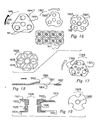
- Disks from Figs 1 to 15 have circular profiles. Therefore we have invented a disk 1600 having several segments 1603 removed, as shown in Fig 16. These segments may be straight (1603), or curved (1604) or even gap-like (1605).
- the centre of each disk may be brought slightly closer to adjoining disk centres, so that more disks can be cut one by one or in stacks (if the stock is multi-layered) from a given area of stock material, as shown at 1606 which is one example of closer packing of disks having segments cut off.
- the inner profile of one segment may comprise the circumference of a neighbouring disk. This inner profile may be a deeper indentation (and called a "throat") (and more than 5 throats may be a satisfactory number), or may be curved, with a sharper leading angle and a shallower trailing angle. Possibly the stamped-out portions can be recycled and used on flap disks.
- Fig 21 shows an example flap at 2114 and how 15 flaps (2115) can be cut at the same time as one disk is made, leaving very little waste material.
- air may be carried to the surface presumably as shown in Fig 6 and here it helps to cool the work, blow dust away from the site of abrasion, and remove broken-off abrasive particles (which being hard are likely items to cause abrasion of the tool itself) from the working area. This is most likely to occur using the air scoop illustrated in Fig 6 and this is worth explaining.
- the arrow 615 shows the direction of movement of the backing plate in relation to the air and the work surface. The portion of the backing plate leading the aperture 612 is cut away, and the trailing edge 613 may be brought upward as a kind of scoop, so that some air is rammed into the aperture 612.
- the contours of the back of the backing plate often generate a negative pressure within the aperture through the backing plate and this may give rise to an air flow within the aperture in the opposite direction, that is, away from the work surface. In either case there is turbulence generated at the work surface and this helps significantly in swarf removal. Careful contouring of the aperture openings in the backing plate can enhance this effect.
- a rake (or slant) of the leading and trailing edges of the holes that are made through the sanding disk itself might, in addition to providing snagging protection, somewhat enhance air flow, it is generally difficult to produce a substantial air turbulence effect in such a thin material and this function is preferably provided largely by building a rake effect into the backing plate, which may be 3-5 mm thick in the region of the holes. This is shown in Fig 6; a shaped sheet is shown in fig 5 or Fig 18. (Of course a thicker sanding disk will be capable of supporting fully functional raked holes and could show the claimed effect even in the absence of a backing plate.
- FIG 5 shows the preferred arrangement and in that drawing 500 is a cross section through a portion of a sanding disk or through a backing plate, including a gap or aperture.
- the preferred direction of rotation is indicated by the arrow 507 and the abrasive surface is downwards.
- the leading edge 505 of an aperture or gap 502 is slanted to leave an acute angle at the edge closest to the abrasive surface, while the trailing edge 504 is slanted so that an obtuse angle is closest.
- Fig 18 shows a raked hole 1801 within a sanding disk 1800, its capability enhanced by forming of the material of the sanding disk or backing plate, according to the invention.
- the leading edge 1803 is generally not deformed but the trailing edge 1802 is bent away from the work surface.
- the region 1804, though abrasive, is unlikely to catch on a projection even if the disk is turning slowly because it is at a gentle slant.
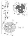
- Two backing plate outlines of the invention are shown 300 and 400 respectively in Figs 3 and 4; Fig 4 is "improved” in that the periphery of the disk is extended outwards from the position (shown by dotted lines 301) of Fig 3.
- These backing plates include gaps 303.
- the arrow 403 shows the direction of rotation. It is possible to produce a resilient backing plate that extends to substantially the full diameter of a sanding disk and in this case it may be preferable to provide apertures rather than gaps. Preferably the number and placing of holes in the sanding disk match those of the backing plate.
- a sanding disk on a grinder might visually align the ventilation/viewing holes 101 in the sanding disk with the gaps or holes 303 in the backing plate. Or he/she might use a locating peg or pin (that shown at 603 in fig 6 is one embodiment; fig 23 is another) in order to hold the disk in place during rotation of the tightening nut. This is a relatively precise way to align the disk. Preferably the locator peg is removed before use.
- Fig 9 shows at 900 a sanding disk 100 beneath a backing plate 401, with the holes of the sanding disk in good alignment with the gaps of the backing plate.
- Fig 9 also illustrates a sanding disk having locator holes 905 which substantially match holes 601 in the corresponding backing plate.
- the backing plates of this invention assist ordinary sanding disks - those that are solid disks - thanks to their resilience.
- Figs 6, 7, and 8 show some preferred backing plates from the side - elevation view. That of Fig 6 (600) is preferably made of a resilient compound such as a rubber or a plastics material and is relatively stiff because its profile remains thick relatively close to the edge. Note the locator hole 601 for use with a locator peg 603.
- the backing plate of Fig 8 (at 800) is more resilient (assuming similar materials) because the outer portion is relatively thin close to the edge.
- Fig 8 also shows a curved or dished shape which we have found preferable - it allows use of the resilience of the sanding disk itself (803 in Fig 8) alone when lightly sanding an object. A flat sanding disk may, after some use itself may take on a slightly dished appearance because of the way that force is applied about the edge of the disk. Perforated disks are more resilient than unperforated disks.
- Fig 6 also includes one means (of many possible methods) to conveniently set the orientation of the sanding disk in relation to the backing plate, when mounting a new disk on an angle grinder.
- Corresponding orientation holes 905 are provided in sanding disks, and as can be seen, these are preferably in a fixed relationship to the repeating structures of the sanding disk, so that for example three possible satisfactory orientations of the sanding disk results in three holes 905.
- a locating peg or pin (shaft 603 and head 604) through the disk and into the corresponding hole in the backing plate so that the disk is held in substantially the correct orientation while tightening the retaining nut.
- the locating pin which may be made of a plastics material, is then removed.
- a typical operator may use a nail or the like as a substitute for a locating pin, , and clearly it is useful to remove the nail before commencing use. (Locating pins may be cheap enough to pack with every sanding disk).
- locator peg structures may serve a dual purpose of shearing and giving way if too much torque exists between the sheet at the disk - if, for example, a protruding object is inadvertently gripped.
- Fig 17 shows the rear (non-sanding) face of a backing plate 1700 of a type with one or more segments 1701 removed, having increased edge visibility during use. Extra raked cooling holes 1702 are also provided.
- the segments 1701 which, like the larger viewing apertures, are intended to line up with corresponding voids in the sanding disk in order to provide visibility of the work during the actual sanding operation.
- the holes together with the preferred type of backing plate give the sanding disk more resilience than an ordinary disk used with an ordinary hard backing plate.
- the disk/plate movement can assist air to reach the rear of the disk and cool it.
- a backing plate having channels to circulate the air in the space between the backing plate and sanding disk.
- Fig 7 shows the principles.
- the disk 700 shows the rear (operator side) of a disk, with air holes shown at 703 and 705. Buried channels spiral out through the substance of the disk to reach the sanding side (see 701) where they may lead into the viewing/cooling apertures 702 or be made into channels 706 that lead out to the circumference. Centrifugal air movement occurs when the assembly rotates. This type of configuration is useful with thick backing plates - such as the foam ones favoured by auto refinishers.
- Backing plates are preferably coloured black, in order to enhance visual contrast for a person looking through a spinning disk and relying on persistence of vision to see the work behind. This colour is less obtrusive than white, which tends to result in a greying out of a view of a work surface seen through a white or other light-coloured disk.
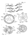
- Fig 10 shows some variations by means of which the sanding disk itself 1000 can be made frangible. It is provided with shearing/tearing points 1003 (sharp-cornered apertures) or alternatively circular apertures at 1004, or alternatively a series of tabs 1006 directed towards the centre so that the weakened zone gives way if an excessive torque is applied.
- a retaining nut 1001 for holding the sanding disk and the backing plate onto an arbor of an angle grinder is also drawn; its sectional view is at 1005.
- the disk 1000 remains captive beneath the periphery of the head of the nut after shearing, preferably provided with a raised portion 1002 to allow slippage, so that the disk does not fly free of the tool and possibly cause injury.
- Most nuts have a chamfer 1007, as shown in the example 1006, to aid in gripping the disk.
- the nut of 1011-1012 is designed to hold only the backing plate to the arbor, and assumes that the sanding disk is held onto the backing plate by other means, such as the projections 805 shown in Fig 8.
- the disk in Fig 10 shows raised portions trailing the holes, as at 1013.
- Fig 11 shows three examples in section; all of which can be made in a resilient material as a casting or forming operation.
- Feature 1102 illustrates a V-shaped tongue-and-groove formation while 1104 shows a more tongue-like variant and 1103 shows a slip ring (which may be embedded in either the inner or outer portion of the plate, or even both.
- the version shown at 1102 may be liable to give way if too great a side force is applied.
- Any of these clutches may be provided with a regular distortion of the sliding surfaces (such as a ratchet type of shape, or a shear pin 1106) so that slipping of the clutch is clearly evident during use as a kind of vibration, noise, chatter, or free spinning and the operator will know to reduce the pressure applied. Holes to engage with a tightening spanner may be provided as at 1107.
- An improved clutch or release mechanism for a backing plate for an angle grinder can be made from a modified retaining nut and thrust washer, as shown in Fig 19 which shows this assembly 1900 in section.
- the thrust washer 1904 differs from the type normally sold with backing plates by (a) having the spigots (that engage with depressions in the backing plate) deleted, and by having an extended shaft.
- This and the extended shaft of the retaining nut 1901 are made to be of such a length that, when screwed together by tightening the retaining nut about the backing plate 1907, the backing plate is gripped only tightly enough to hold it during normal working torque. When excess torque is applied, the backing plate can slow or stop while the nut/washer assembly 1901 + 1904 continues to be driven.
- a noise or cause vibration so that the operator is aware that slippage is occurring before friction-developed heat affects the equipment.
- This may comprise a toothed hub 1909 in the backing plate, which engages with a pawl 1905, or a spring and ball, or shear pin, or the like projection(s) from one or other of the thrust washer 1904 or the retaining nut 1901.
- the teeth may be included in the nut/washer assembly and the projection in the backing plate).
- the combination of teeth and pawl may themselves partially or completely define the torque at which the clutch gives way.
- Figure 12 illustrates a version 1200 of the sanding disk of the above cited PCT, bearing multiple flaps of abrasive material. These devices generally come with their own backing plate 1202. Flaps may be attached in radial lines as at 1201, or at a slant (as beside the marker 1202). A series of small holes 1203 provide a weakened zone in case the disk grips an object, but a preferred weak point is a slip ring 1303 and a shear pin 1304. The tangential flaps may tend to cause the wheel to become less dished when it spins.
- Fig 13 shows another (1300) sanding disk having flaps, where the flaps of abrasive material 1301 are interrupted by the apertures 1302. This gives the work surface a series of rest times and assists in cooling.
- Fig 14 is provided to show that holes may be placed at various distances from the centre of the flapper disk, and preferably they are arranged so that the innermost perimeter of an outer hole 1401 is closer to the centre than the outermost perimeter of an inner hole 1402, so that an operator can see through substantially all of the disk when using the tool.
- the holes 1403 (though not essential) are here provided for imposing a weakened zone. Generally though the flaps will be torn off if overstressed.
- a clutch or shear pin arrangement or the like can be provided (Fig 13). Similar holes could be used in the contact-adherent system of Fig 15, where a sticky (or "Velcro" fitted) disk 1501 is stuck down over its entire surface onto a disk 1502.
- Backing plates can be provided with a built-in thread matched to that of the arbor of the angle grinder. In that case they can also be provided with holes to engage with a tightening spanner. Backing plates can be provided with perhaps 3 to 7 stubby projecting pins that engage with alignment apertures stamped through sanding disks. Examples are shown in Fig 8 which shows a backing plate seen from the side, with projections 805 aligned with similar-sized apertures 806 in a sanding disk 803. (Fig 23 shows another system).
- the stubby pins which are not long enough to reach the work surface during use, also serve to lock the disk to the spinning packing plate during use. They transfer the torque from the arbor, via the backing plate, to the disk. In the event of excessive torque, the stubby projecting pins may break off, or the sandpaper, otherwise only retained on the arbor but not otherwise locked in rotation to it, may come out of alignment with the stubby projecting pins.
- backing plates include gaps to overlay sanding disk apertures, they can be made with gradual trailing edges so that if a projection gets through a sanding disk it can tear out the edge of the disk and escape from the backing plate, probably causing a jerk to the angle grinder but at least not continuing to be trapped.
- Fig 9 shows this, along with a raked edge 904.
- backing plate comprises a thick, foam-filled (so that it is soft and resilient) backing plate, typically 24 mm thick and 200 mm in diameter. This is used in conjunction with adhesive-backed disks of sandpaper, and the combination is widely available and generally used for automotive finishing work.
- Fig 7 shows one system for cooling channels.
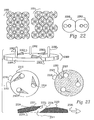
- Fig 22 shows relevant diagrams; a fitting plate 2301, a typical pre-cut sanding disk 2320, and the front surface of the backing plate 2310.
- a fitting plate for use with our modified foamy backing plate includes one or more locating pins 2302 placed so as to mate, when in the correct orientation, with locating holes 2312 constructed within the foamy backing plate 2310 and to be fed through holes 2322 in the sanding disk, which is placed, abrasive side down, upon the jig or fitting plate 2301 prior to the above mating of locating pins with holes.
- retaining clips may be used on the jig in order to hold flat any sheets which may tend to curl.
- trough-forming projections 2302 located upon the fitting plate 2301 at positions corresponding to the trailing edges of the larger viewing/cooling apertures in the disk 2321 and the backing plate 2311 (these holes preferably being raked as shown at 2316 and 2336).
- the projections push the covering parts of the sanding disk into recesses provided in the backing plate.
- the disk preferably has slits 2323 cut on the trailing side of the larger apertures to allow for this distortion).
- the sanding disk is provided with pressed-in abrasive material on the raised-from -the work trailing edge of the larger apertures, to assist in minimising the risk of catching a protruding object during use.
- air flow over the work originating from turbulence caused by the viewing/cooling apertures assists in keeping the cutting cool.
- These fittings 2334 may simply clip into place using inherent shape and resilience, or they may be held in place with fasteners, such as screws 2331.
- the fittings may also include projections 2332 which rise above the surface of the foamy backing plate 2330 on the operator's side and act during use may act to enhance airflow down the apertures and towards the work surface. Hence the abrasive surface 2333 is cooled, while the operator has some chance to see the work through the same holes. (These air scoop formations are concealed from the operator by remaining beneath the guard of the angle grinder).
- Fig 20 shows some designs.
- a preferred guard 2003 is mounted on the angle grinder body 2001, and comes forward over the sanding disk 2004 as far as is necessary to provide protection.
- a preferred mounting site employs the threaded holes provided for the handles 2002, for these tend to be standard features between different types of angle grinder. Generally holes are provided on each side (as shown) but the operator has only one handle to be put in one side or the other depending on handedness.
- the guard 2003 may be held between a handle and the body of the grinder, or it may be held in an un-used hole by a bolt. (The handle may be placed on the right or the left side according to the handedness of the operator).
- a guard may be made by pressing or forming so that lugs 2005 are bent upwards from the plane of the guard.
- a side view of two versions is shown at 2014; the lower one has at 2006 a slotted hole so that it can be moved forwards or backwards.
- Preferred guards are transparent, so that the operator can see through them and may be able to have the entire disk covered by the guard - yet still be able to see through the equipment to the work during abrasion.
- Another version is shown at 2015; this version is adjustable by means of a slot 2011, a wing nut 2012, and a pivot nut 2010, which allow the curved portion 2007 of the guard to move forwards and backwards relative to the angle grinder, onto which the guard is held by bolts 2008 and 2009 onto the brackets 2013 entering the handle mounting holes. (The handle may replace one of the bolts). 2016 is an optional trough on the other side, to allow more flexibility in adjustment.
- Preferred guards are also capable of adjustment to and from the edge of the sanding disk, so that the amount of exposed disk can be optimised according to various working conditions.
- an appropriately shaped guard will help channel air flow generated during grinding and ensure that swarf produced is ejected with the radially outwardly, even when the air turbulence generated by the viewing apertures, especially as sculpted in accordance with a preferred feature of the invention, tends to draw air from the grinding surface back towards the operator. Any such material is swept away by the swirling air currents generated between the rotating disk/backing plate and the guard itself.
- stamping cost per disk may be of the order of 5c plus wages for the workers attending the machine and possibly the expense of upgrading to heavier presses.
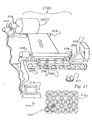
- a liquid cutting process as shown in Fig 21, in which a fine jet of water (or some other suitable liquid) forced out of a nozzle at a high pressure is used to make precise cuts in a sheet of stock sandpaper in order to prepare sanding disks.
- a fine jet of water or some other suitable liquid
- abrasive granules may be added to the water stream as is practised in the art (but see below).
- the liquid cutter would, as is customary in water cutting techniques used in other fabrication processes, use liquid raised (in the supply pump 2103) to a pressure of perhaps some 30,000 pounds per square inch pressure, brought by means of a flexible hose 2104 to ultimately emerge from a nozzle 2105 close to the material to be cut.
- Spray and waste is collected, preferably actively with the aid of air jets and vacuum cleaners (not shown), and the fluid may be filtered well and re-used.
- the nozzle is moved relative to the stock by computer control, preferably to a precision of ⁇ 0.1 mm over the width of a single sanding disk, although a precision of ⁇ 1 mm might be sufficient.
- the sheet of stock coming off a roll 2101 may be moved forward and backward by gripping rollers 2109, one steel and one (against the abrasive side) of rubber, to cause movement in one orthogonal axis, and the nozzle or nozzle array 2105 may be moved from side to side on a rail or some other suitable support, in the other orthogonal axis.
- Stepping motors ( 2106, 2107) coupled to rollers 2109, 2108 represent one preferred source of motive power since they are easily coupled to a computer-based controller 2110 by known interfaces.
- the HPGL plotter language (or similar) might be selected as a standardised way of instructing the stepping motor interfaces.
- the unit step size of the stepping motors in both axes is similarly related to relative work/cutter movement so that when a circle is intended, it is obtained.
- Software can compensate for constant errors of scale, so the above requirement is simply a preferred feature.
- a number of nozzles 2105 are held in a gang formation on a rigid beam or on a rigid plate 2113, so that a number of identical disks 2102 can be cut from the stock roll in one set of controlled movements.
- Fig 21 does not show the details of a practical machine.
- the lengthwise movement of the stock should preferably involve a low-resistance, low-momentum action and (as in reel-to-reel tape drives for computers) a loop of material may be drawn off and reduced or lengthened as forwards or backwards movement occurs.
- the roller 2118 could be relatively lightly springloaded so that it tends to push up. Motors such as 2117 driving the rolls are useful to reduce drag on the rollers 2109 at the cutting machine.
- abrasive may not be necessary if the machine is made so that the jet first hits the abrasive side - for then that abrasive acts as the cutting abrasive.
- Fig 21 shows an additional roll 2116 behind a first roll 2101 and possibly further rolls of stock can be added. Or the stock may be wound as a multi-ply single roll.
- laser cutting may be used as an alternative (wherein an infra-red transmitting lens for focusing radiation to a point; the lens being coupled to a carbon-dioxide continuous wave laser, replaces the liquid nozzle, but we understand that this is more expensive and takes more skill to use and maintain the laser(s), and there will be noxious fumes to dispose of, arising from the backing material and glues.
- Sanding disks tend to curl up when packed and they are prone to deterioration if water gets into the backing material, particularly during storage. It tends to do this from cut edges.
- the cutting liquid may also be provided with sealant properties. It may be a meltable solid, such as a wax - that is molten when it is used as a jet. Some that sets over the sanding disk, where it can then can act as a lubricant during use. Or it may be water or a watery liquid including some dissolved material that acts as a varnish, or as a sealant. Or it may be a polymerisable material such as a polyurethane paint.
- the illustration shows 15 flaps at 2115 made from the otherwise waste stock around a single example apertured and gapped sanding disk.
- Most sanding disk shapes occur in the libraries of typical computer drawing packages.
- economy in cutting strokes leads one to prefer those shapes of sanding disk that include straight (or other) edges common to more than one disk, as shown in the example set 2112 which would result in very little waste, especially if flaps 2115 are cut from the inter-disk diamond shapes and from the larger disk apertures also.
- the path of the cutters may be programmed so that all removed material is shredded finely. When gathered up and filtered, this material can be used in the manufacture of grinding wheels of various types. In any case there will always be some finely divided material recoverable from the fluid drains of the cutting machine.
- Fluid cutting is less likely than pressing to initiate stresses at the time of manufacture at a sharp corner or blind end of any cut other than a circular outline. (Cracks are expected to tend to propagate from stresses arising at corners).
- the preferred anti-snagging shapes to be provided about the trailing edges of the apertures cut through our type of sanding disk by creating a raised "hood" over each hole are preferably created in a separate pressing step to the cutting step, whether the cutting step uses dies or otherwise.
- the fluid cutting method of preparing sanding disks of the above PCT is also applicable to conventional sanding disks, that is, circular shapes with perhaps a central, concentric mounting hole and no other.
- Fig 22 shows some other possible layouts for sanding disks of the PCT though it is impossible to show all options. Presumably optimisation can be varied according to relative costs.
- Fig 22 shows, at 2202 a single aperture disk, having a balancing segment removed from its periphery, and a mirror image at 2203.
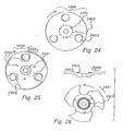
- the sanding disk 2400 of Fig 24 has (a) three viewing and principally anti-snagging apertures 2403 (which have been drawn to show the limits of the preferred recess made by pressing the material of the disk inward, and (b) three drive/alignment holes 2401, at about the same radius as a tear-out zone 2402.
- all three of the drive/alignment holes are driven by means of corresponding pins held in the backing plate.
- the sanding disk when connected to the drive pins, is in correct alignment on the backing plate of the invention. If the disk is, in use, exposed to too great a stress the drive pins will destroy the tear-out zone 2402, so that the disk will come free of the backing plate and the disk can no longer be driven.
- 2500 is the assembly
- 2501 is a central register plate on the backing plate of the invention
- 2502 is the sanding disk of the above cited PCT
- 2503 is a breakout zone on the sanding disk
- 2504 is a sanding disk to backing plate alignment aperture and/or pin.
- An additional enhancement to the backing plates of this invention is to provide a grip pad 2602 for gripping the sanding disk of the above cited PCT by means of a nut pressing the disk between itself and the grip pad, inside the concentric tear-out zone.
- the grip pad 2602 is like a ring of sandpaper placed concentrically around the aperture provided for the arbor of the angle grinder. (In our prototypes, it is a ring of sandpaper glued onto the backing plate, but some other durable material which digs into the back surface of the sanding disk may be used instead - such as an insert of a knurled or deeply etched metal, or a portion of a plastic surface incorporating projections. The projections or rough surface may not be necessary.
- Spigots on a metal washer are one preferred formation of a roughened surface.
- a simple metal washer may suffice, if the disk is tightened sufficiently against it.
- This concentric ring is intended to grip a sandpaper disk (such as Fig 24) inside its tear-out hole zone, so that if the disk in use is exposed to too great a stress it will come free of the backing plate which can no longer drive the disk.
- This ring (as shown in the section 2600) is that the slight elevation of the gripping surface 2602 provides further air movement between the sanding disk and the backing plate 2603 during use, so cooling the rear of the sanding disk.
- grip pad and the drive pins are preferably not used together; though this opinion depends on the relative effectiveness of each construction as it is implemented in a commercial embodiment.
- Figs 27 to 30 show a contact sanding disk of the above cited PCT and a backing plate suitable for use with such a contact disk.
- This type of disk is used particularly for finishing work on automobile bodies, for producing a smooth surface on or under painted layers.
- the user of this kind of disk is faced mainly with the problem of securing a long disk life before it gets clogged up, which requirement can also be expressed as the problem of keeping the disk and work surface cool during sanding.
- a good vacuum can be created within the relatively thick body of the backing plate during rotation, by making channels (see Fig 7; 706) which run substantially centrifugally, so that air is flung out from them and extracted from apertures (such as 2803 or 2905) passing through and near the centre of the contact adhesive disk. These apertures may also serve as locating or aligning holes. If the pins used projected right through the backing plate, it may be preferable to seal off those holes with a flap of a resilient material, so that the effects of the vacuum are concentrated on the abrasive surface. Preferably the channels are exposed when the sanding disk is removed, so that accumulated debris can be flushed out.
- Fig 27 simply shows the rear (operator's view) surface of an unmodified backing plate having a nut 2701. Air extraction (vacuum) channels are not shown.
- Fig 28 shows a three-hole version 2800 of a contact sanding disk with (a) vision/cooling apertures 2801 in three pairs of two, (b) indexing/alignment holes 2803, (c) fold lines 2805 about a cut 2804, and (d) vacuum and alignment apertures. Note that in this version the pairs of vision/cooling apertures 2801 are arranged to be not on radii of the disk.
- Fig 29 shows another version of a contact sanding disk with the 22 mm diameter vision/cooling apertures aligned along radii, (b) 8 mm diameter vacuum/ alignment holes, and (c) fold lines.
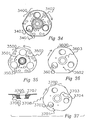
- Figs 30 to 33 show a four-sided sandpaper disk system.
- the disk 3000 - fig 30 has wing tips 3003 which help increase air flow between the disk and the material being abraded, as well as reducing the impact of rim contact, four 16 mm diameter viewing holes 3001 which are the primary source of ventilation, and a central tear-out hole zone 3002, inside an array of alignment holes 3004.
- Fig 31 shows at 3100 the four-sided sandpaper disk 3101 in position upon (behind) a backing plate 3102. Note the alignment (any one of 4 positions) of the viewing/ventilation holes in the sanding disk behind the raked holes of the backing plate.
- Fig 32 shows the work surface side of a backing plate 3200 compatible with the sanding disk of Fig 30.
- This plate has a grip pad 3203, four cooling channels (3201), four structurally weakened breakout zones (holes 3202) in case some object projects through the viewing/ventilation apertures, and four index alignment apertures.
- Fig 33 shows a backing plate 3304 in section and a matching four-sided sanding disk 3300, having four viewing/ventilation apertures with anti-snagging features 3303, thinned break-out zones 3301, and a concentric weakened or tear-out zone inside the alignment holes.
- the sanding disk also has wing tips 3302 (see above).
- Figs 34 to 37 show a three-sided sandpaper disk; similar to the above four-sided version.
- Fig 34 shows a disk in position upon a suitable backing plate 3400.
- holes 3401 give the backing plate a weakened zone so that it can let the object through. (We should say that we find it almost impossible to make an object catch in the holes of a spinning disk; the most likely circumstances are when the disk is spinning only very slowly).
- Fig 35 shows a backing plate 3500 compatible with the sanding disk 3600 of Fig 36, having a grip pad 3503, and index alignment holes 3502.
- Fig 36 shows a three-sided sandpaper disk 3600 with (a) wing tips (not labelled), (b) ventilation/viewing holes 3601 fitted with anti-snagging features, (c) a concentric tear-out hole zone near the central aperture, at 3603, and (d) alignment holes 3602.
- Fig 37 shows a backing plate in section (3705) and a matching three-sided sanding disk (3700), having ventilation holes 3702 with anti-snagging features, break-out zones 3701 on the trailing side of the ventilation holes, and a concentric weakened or tear-out zone 3703.
- Alignment holes are provided at 3704.
- the backing plate 3705 has a grip pad 3707 - like a ring of sandpaper - intended to grip the sandpaper disk concentrically inside its tear-out hole zone.
- the area 3706 is provided with apertures for promoting air circulation for cooling the working area during use. Wing tips are again provided and drawn, as at 3708.
- Wing tips or deliberately formed vanes may be used to entrap air about the circumference of the sanding disk.
- These may be used in conjunction with an air containment "skirt" around the guard of the angle grinder and projecting towards the work surface, the skirt being made of a soft and preferably transparent resilient material (such as polyurethane) and including a positioned gap placed so that dust is ejected in one direction rather than in all directions.
- a dust collecting device can then be installed so that a substantial proportion of the dust is retained.
- This type of guard is designed for use with the thick, resilient backing plates intended for use with contact sheets of sandpaper and for use in applications such as automobile bodywork finishing; in manufacture or repair.
Landscapes
- Engineering & Computer Science (AREA)
- Mechanical Engineering (AREA)
- Polishing Bodies And Polishing Tools (AREA)
- Grinding-Machine Dressing And Accessory Apparatuses (AREA)
- Power Steering Mechanism (AREA)
- Finish Polishing, Edge Sharpening, And Grinding By Specific Grinding Devices (AREA)
- Braking Arrangements (AREA)
- Cylinder Crankcases Of Internal Combustion Engines (AREA)
- Toys (AREA)
Applications Claiming Priority (11)
| Application Number | Priority Date | Filing Date | Title |
|---|---|---|---|
| NZ28063495 | 1995-12-08 | ||
| NZ28063495 | 1995-12-08 | ||
| NZ28071095 | 1995-12-19 | ||
| NZ28071095 | 1995-12-19 | ||
| NZ28078196 | 1996-01-04 | ||
| NZ28078196 | 1996-01-04 | ||
| NZ28087696 | 1996-01-23 | ||
| NZ28087696 | 1996-01-23 | ||
| NZ28096496 | 1996-02-09 | ||
| NZ28096496 | 1996-02-09 | ||
| PCT/US1996/018927 WO1997021520A1 (en) | 1995-12-08 | 1996-11-21 | Backing plates for abrasive disks |
Related Child Applications (1)
| Application Number | Title | Priority Date | Filing Date |
|---|---|---|---|
| EP98202730.2 Division-Into | 1998-08-14 |
Publications (2)
| Publication Number | Publication Date |
|---|---|
| EP0874717A1 EP0874717A1 (en) | 1998-11-04 |
| EP0874717B1 true EP0874717B1 (en) | 2005-08-31 |
Family
ID=27532644
Family Applications (3)
| Application Number | Title | Priority Date | Filing Date |
|---|---|---|---|
| EP96942067A Expired - Lifetime EP0874717B1 (en) | 1995-12-08 | 1996-11-21 | Backing plates for abrasive disks |
| EP98202730A Expired - Lifetime EP0882551B1 (en) | 1995-12-08 | 1996-12-02 | Sanding disks |
| EP96943551A Expired - Lifetime EP0868262B1 (en) | 1995-12-08 | 1996-12-02 | Improvements to sanding disks |
Family Applications After (2)
| Application Number | Title | Priority Date | Filing Date |
|---|---|---|---|
| EP98202730A Expired - Lifetime EP0882551B1 (en) | 1995-12-08 | 1996-12-02 | Sanding disks |
| EP96943551A Expired - Lifetime EP0868262B1 (en) | 1995-12-08 | 1996-12-02 | Improvements to sanding disks |
Country Status (14)
| Country | Link |
|---|---|
| US (1) | US6312325B1 (enExample) |
| EP (3) | EP0874717B1 (enExample) |
| JP (8) | JP3479083B2 (enExample) |
| KR (3) | KR100329307B1 (enExample) |
| AT (3) | ATE303232T1 (enExample) |
| AU (3) | AU699881B2 (enExample) |
| BR (2) | BR9611910B1 (enExample) |
| CA (3) | CA2238718C (enExample) |
| DE (3) | DE69635133T2 (enExample) |
| DK (3) | DK0874717T3 (enExample) |
| ES (3) | ES2248824T3 (enExample) |
| MX (2) | MX9804545A (enExample) |
| TW (2) | TW393385B (enExample) |
| WO (2) | WO1997021520A1 (enExample) |
Cited By (3)
| Publication number | Priority date | Publication date | Assignee | Title |
|---|---|---|---|---|
| US9744647B2 (en) | 2013-06-28 | 2017-08-29 | Saint-Gobain Abrasives, Inc. | Thin wheel reinforced by discontinuous fibers |
| US9776303B2 (en) | 2013-06-28 | 2017-10-03 | Saint-Gobain Abrasives, Inc. | Abrasive article reinforced by discontinuous fibers |
| US9855639B2 (en) | 2013-06-28 | 2018-01-02 | Saint-Gobain Abrasives, Inc. | Abrasive article |
Families Citing this family (87)
| Publication number | Priority date | Publication date | Assignee | Title |
|---|---|---|---|---|
| GB2332162B (en) * | 1997-12-12 | 2002-09-18 | Simon Henry Jordan | Grinding disc |
| US6277012B1 (en) * | 1998-01-14 | 2001-08-21 | Norton Company | Disk locking device |
| US6077156A (en) * | 1998-12-16 | 2000-06-20 | Norton Company | Grinding disc |
| US6159089A (en) * | 1998-12-16 | 2000-12-12 | Norton Company | Grinding system |
| RU2210490C2 (ru) * | 1999-04-23 | 2003-08-20 | Сент - Гобэн Абразивс, Инк. | Вращающийся абразивный инструмент |
| TW567116B (en) * | 1999-04-23 | 2003-12-21 | Saint Gobain Abrasives Inc | Rotary abrasive tool |
| US6062965A (en) * | 1999-06-03 | 2000-05-16 | Norton Company | Backup pad for rotary grinder |
| KR100314287B1 (ko) * | 1999-07-29 | 2001-11-23 | 김세광 | 연마 휠 |
| JP4817478B2 (ja) * | 2000-02-16 | 2011-11-16 | ケヰテック株式会社 | バフ研磨具 |
| JP2002046073A (ja) * | 2000-08-04 | 2002-02-12 | Kanto Seito Kk | 研磨用軟質孔あきディスク及びその製造方法 |
| US6722955B2 (en) * | 2001-01-10 | 2004-04-20 | 3M Innovative Properties Company | Buckup plate assembly for grinding system |
| US20040180618A1 (en) * | 2001-09-03 | 2004-09-16 | Kazuo Suzuki | Sheet-form abrasive with dimples or perforations |
| JP2003103469A (ja) * | 2001-09-27 | 2003-04-08 | Noritake Super Abrasive:Kk | カップ型砥石 |
| US6758732B1 (en) | 2001-12-01 | 2004-07-06 | Mark A. Hilton | Backing plate and disc configured for blowing angled grinding |
| US20030143926A1 (en) * | 2002-01-30 | 2003-07-31 | Raffi Piliguian | Grinding or polishing arrangement |
| DK174530B1 (da) * | 2002-02-23 | 2003-05-12 | Mostrup Holding Aps | Cirkulært skæreskive til håndholdt værktøj, håndholdt værktøj med cirkulær skæreskive og med beskyttelsesskærm samt anvendelse af sådan skæreskive |
| JP4331001B2 (ja) * | 2002-04-12 | 2009-09-16 | プレシメッド エス.アー. | 低侵襲外科用リーマと連結部 |
| WO2004045805A1 (ja) * | 2002-11-20 | 2004-06-03 | Yanase Kabushiki Kaisha | 回転研磨材 |
| US7220264B1 (en) | 2003-03-12 | 2007-05-22 | Biomet Manufacturing Corp. | Minimally invasive reamer |
| USD501857S1 (en) | 2003-04-24 | 2005-02-15 | 3M Innovative Properties Company | Abrasive member |
| USD513884S1 (en) | 2003-04-24 | 2006-01-31 | 3M Innovative Properties Company | Abrasive sheet |
| USD509667S1 (en) | 2003-04-24 | 2005-09-20 | 3M Innovative Properties Company | Abrasive sheet |
| US7094140B2 (en) * | 2003-06-03 | 2006-08-22 | Onfloor Technologies, L.L.C. | Abrasive sanding surface |
| JP3809158B2 (ja) * | 2003-09-02 | 2006-08-16 | 大宝ダイヤモンド工業株式会社 | 研削ディスク |
| US7275302B2 (en) * | 2003-12-09 | 2007-10-02 | Seagate Technology Llc | Method of forming a disc pack |
| US20060019218A1 (en) * | 2004-07-20 | 2006-01-26 | Kuo Eric E | Combined interproximal reduction (IPR) disc/measurement tool |
| US20060019579A1 (en) * | 2004-07-26 | 2006-01-26 | Braunschweig Ehrich J | Non-loading abrasive article |
| JP2008526529A (ja) * | 2004-12-30 | 2008-07-24 | スリーエム イノベイティブ プロパティズ カンパニー | 研磨物品およびその製造方法 |
| DE202005009665U1 (de) * | 2005-06-17 | 2006-11-02 | Rhodius Schleifwerkzeuge Gmbh & Co. Kg | Schleifscheibe mit Sichtaussparungen |
| US7258705B2 (en) * | 2005-08-05 | 2007-08-21 | 3M Innovative Properties Company | Abrasive article and methods of making same |
| US7252694B2 (en) * | 2005-08-05 | 2007-08-07 | 3M Innovative Properties Company | Abrasive article and methods of making same |
| US7883398B2 (en) * | 2005-08-11 | 2011-02-08 | Saint-Gobain Abrasives, Inc. | Abrasive tool |
| USD538313S1 (en) | 2005-09-16 | 2007-03-13 | 3M Innovative Properties Company | Abrasive article with holes |
| US7244170B2 (en) * | 2005-09-16 | 2007-07-17 | 3M Innovative Properties Co. | Abrasive article and methods of making same |
| US7390244B2 (en) * | 2005-09-16 | 2008-06-24 | 3M Innovative Properties Company | Abrasive article mounting assembly and methods of making same |
| US7393269B2 (en) * | 2005-09-16 | 2008-07-01 | 3M Innovative Properties Company | Abrasive filter assembly and methods of making same |
| USD538312S1 (en) | 2005-09-16 | 2007-03-13 | 3M Innovative Properties Company | Abrasive article with holes |
| USD536714S1 (en) | 2005-09-16 | 2007-02-13 | 3M Innovative Properties Company | Abrasive article with holes |
| DE102005054578A1 (de) * | 2005-11-16 | 2007-05-24 | Robert Bosch Gmbh | Trennscheibe |
| USD533200S1 (en) | 2006-02-01 | 2006-12-05 | 3M Innovative Properties Company | Abrasive article with holes |
| USD541317S1 (en) | 2006-02-01 | 2007-04-24 | 3M Innovative Properties Company | Abrasive article with holes |
| USD532800S1 (en) | 2006-02-01 | 2006-11-28 | 3M Innovative Properties Company | Abrasive article with holes |
| USD543562S1 (en) | 2006-02-01 | 2007-05-29 | 3M Innovative Properties Company | Abrasive article with holes |
| US20080096167A1 (en) * | 2006-08-22 | 2008-04-24 | Florman Michael J | Grinder disk |
| US7452265B2 (en) | 2006-12-21 | 2008-11-18 | 3M Innovative Properties Company | Abrasive article and methods of making same |
| USD586370S1 (en) | 2007-08-09 | 2009-02-10 | 3M Innovative Properties Company | Random hole abrasive disc |
| US8286291B2 (en) * | 2007-10-02 | 2012-10-16 | Dynabrade, Inc. | Eraser assembly for a rotary tool |
| DK178006B1 (da) * | 2007-12-04 | 2015-03-02 | Flex Trim As | Slibeværktøj samt apparat til slibning af en overflade på pladeformede emner |
| US20090233528A1 (en) | 2008-03-07 | 2009-09-17 | Saint-Gobain Abrasives, Inc. | Floor sanding sponge pads |
| USD645065S1 (en) | 2008-05-22 | 2011-09-13 | 3M Innovative Properties Company | Abrasive article with holes |
| DE102008055797A1 (de) * | 2008-11-04 | 2010-05-06 | Kai Roscher | Schleifmaschine |
| WO2010064380A1 (ja) * | 2008-12-02 | 2010-06-10 | 株式会社三信精機 | 爪研磨機 |
| US8397342B2 (en) | 2008-12-09 | 2013-03-19 | Credo Technology Corporation | Debris removal system for power tool |
| CN102333619A (zh) * | 2008-12-16 | 2012-01-25 | 戴纳布莱德公司 | 用于转动工具的擦除器组件 |
| US8360823B2 (en) * | 2010-06-15 | 2013-01-29 | 3M Innovative Properties Company | Splicing technique for fixed abrasives used in chemical mechanical planarization |
| DE102010052864A1 (de) * | 2010-12-01 | 2012-06-06 | Thyssenkrupp System Engineering Gmbh | Vorrichtung und System zur Herstellung einer Falz |
| US20120190279A1 (en) * | 2011-01-24 | 2012-07-26 | Giovanni Ficai | Ventilating insert for abrasive tools |
| ES2401775B1 (es) * | 2011-05-18 | 2014-09-05 | Herramientas De Diamante, S.A. | Muela en dos partes para mecanizado |
| BR112014016015B1 (pt) * | 2011-12-31 | 2020-12-29 | Saint-Gobain Abrasives, Inc. | artigo abrasivo com distribuição não uniforme de aberturas |
| DE102012220944A1 (de) * | 2012-11-16 | 2014-05-22 | Hilti Aktiengesellschaft | Bearbeitungsscheibe zur Bearbeitung eines Untergrundes |
| DE102013203116A1 (de) * | 2013-02-26 | 2014-08-28 | Robert Bosch Gmbh | Schleifmittelvorrichtung |
| CA2948299A1 (en) * | 2013-05-09 | 2014-11-13 | Lawrence Baker | Blade sharpening system for a log saw machine |
| CA2936432C (en) | 2013-11-11 | 2018-07-31 | Dipl.-Ing. Gunter Wendt Gmbh | Vulcanised fibre grinding tool |
| DE102013017962A1 (de) | 2013-11-11 | 2015-05-13 | Dipl.-Ing. Günter Wendt GmbH | Verbessertes Vulkanfiber-Schleifwerkzeug |
| DE202013010146U1 (de) | 2013-11-11 | 2013-11-26 | Dipl.-Ing. Günter Wendt GmbH | Verbessertes Vulkanfiber-Schleifwerkzeug |
| US9302369B2 (en) * | 2014-01-20 | 2016-04-05 | Pratt & Whitney Canada Corp. | Grinding wheel and method |
| US20160045207A1 (en) | 2014-08-14 | 2016-02-18 | Biomet Manufacturing, Llc | Flexible bone reamer |
| US20170274503A1 (en) * | 2014-08-14 | 2017-09-28 | August Rüggeberg Gmbh & Co. Kg | Grinding element, method for producing the grinding element and injection-molding tool for carrying out the method |
| WO2016065367A1 (en) * | 2014-10-24 | 2016-04-28 | Pitts James Edward | Improved, long-lasting blade holder |
| DE202015100548U1 (de) * | 2015-02-05 | 2015-02-26 | Industrias Tenazit, S.A. De C.V. | Trägerplatte für Lamellenschleifscheiben |
| WO2017032397A1 (de) * | 2015-08-21 | 2017-03-02 | August Rüggeberg Gmbh & Co. Kg | Schleif-werkzeug sowie verfahren zur herstellung eines derartigen schleif-werkzeugs |
| BR102016005744A2 (pt) * | 2016-03-16 | 2017-09-19 | Henrique Messias José | Rapid connection device for the sands applied on rotary axle |
| CH712558B1 (de) | 2016-06-01 | 2020-12-30 | Airtec Ag | Trägerscheibe für eine Bodenbearbeitungsmaschine und Verfahren zur Entfernung von Schmutz und Staub mit einer Bodenbearbeitungsmaschine. |
| TWI595965B (zh) * | 2016-12-30 | 2017-08-21 | Super Master Developing Co Ltd | Abrasive pieces |
| FI131389B1 (en) * | 2017-09-08 | 2025-03-21 | Mirka Ltd | Backing wheel arrangement for a grinding system and grinding system |
| DE202018005258U1 (de) | 2018-11-13 | 2019-01-10 | Hochschule Trier | Scheibenförmiges Werkzeug zur Bearbeitung von Werkstücken, Trennvorrichtung sowie Verwendung einer Trenn-, Schleif- und Polierscheibe zum Erzeugen einer Oberflächenstruktur auf einem Werkstück |
| RS63356B1 (sr) | 2018-11-13 | 2022-07-29 | Klingspor Ag | Disk za sečenje, brušenje i poliranje i postupak za obradu radnih komada |
| US11685016B2 (en) | 2019-08-26 | 2023-06-27 | Lake Country Tool, Llc | Cooling device for a rotating polishing disk |
| KR102182704B1 (ko) * | 2019-12-31 | 2020-11-25 | 주식회사 르본인터내셔널 | 정밀하고 신속한 래핑이 가능한 래핑방법 |
| USD978936S1 (en) | 2020-06-25 | 2023-02-21 | Saint-Gobain Abrasives, Inc. | Floor edger sanding disc |
| USD978934S1 (en) | 2020-06-25 | 2023-02-21 | Saint-Gobain Abrasives, Inc. | Floor edger sanding disc |
| USD978935S1 (en) | 2020-06-25 | 2023-02-21 | Saint-Gobain Abrasives, Inc. | Floor edger sanding disc |
| USD978937S1 (en) | 2020-06-25 | 2023-02-21 | Saint-Gobain Abrasives, Inc. | Floor edger sanding disc |
| CN114871938B (zh) * | 2022-05-09 | 2023-03-28 | 浙江工业大学 | 翼型自悬浮式研磨盘 |
| US12208486B1 (en) * | 2023-09-12 | 2025-01-28 | Daniel Nelson | Secure grinder blade and tapered tool—side locking hub for flush cutting concrete |
| CN117158826B (zh) * | 2023-09-27 | 2025-07-22 | 苏州市春菊电器有限公司 | 一种可旋转的吸尘器移动附件托盘结构 |
| CN119141354B (zh) * | 2024-11-18 | 2025-05-13 | 龙口市智兴机械制造有限公司 | 一种用于汽车底盘支架的打磨设备 |
Family Cites Families (42)
| Publication number | Priority date | Publication date | Assignee | Title |
|---|---|---|---|---|
| FR791127A (fr) * | 1937-01-22 | 1935-12-04 | Perfectionnements aux diffuseurs de télégraphie sans fil | |
| US2633680A (en) * | 1948-10-20 | 1953-04-07 | Goldberg Samuel | Self-cooling buffing wheel |
| US2749681A (en) * | 1952-12-31 | 1956-06-12 | Stephen U Sohne A | Grinding disc |
| US3191351A (en) * | 1963-04-29 | 1965-06-29 | Louis A Balz | Ice drill sharpener |
| US4021969A (en) * | 1976-03-01 | 1977-05-10 | Davis Jr James R | Observable workpiece abrading machine |
| US4188755A (en) * | 1978-04-19 | 1980-02-19 | Ex-Cell-O Corporation | Expandable abrading tool and abrasive insert and washers thereof |
| JPS5593457U (enExample) * | 1978-12-25 | 1980-06-28 | ||
| DE3136402A1 (de) * | 1981-09-14 | 1983-03-24 | Werner Gerhard 6113 Babenhausen Lang | Bohrungsschleifmaschine |
| JPS5844165U (ja) * | 1981-09-19 | 1983-03-24 | 小澤 嘉之 | のぞき穴を設けてある研磨具 |
| JPS5880164U (ja) * | 1981-11-21 | 1983-05-31 | 小澤 嘉之 | のぞき穴を設けて研磨個所を確認しながら研磨できる研磨盤 |
| JPS5942855U (ja) * | 1982-09-08 | 1984-03-21 | 株式会社三興技研 | 研摩用バフ |
| JPS59142059A (ja) * | 1983-01-28 | 1984-08-15 | Nec Corp | 平面研摩方法 |
| EP0175728A1 (de) * | 1984-04-03 | 1986-04-02 | Krohne Messtechnik Gmbh & Co. Kg | Absperr- und regelvorrichtung mit einem drehbaren verschlussteil |
| JPS61152375A (ja) * | 1984-12-26 | 1986-07-11 | Nippon Kouzou Kk | 回転切断刃 |
| JPS61192475A (ja) * | 1985-02-22 | 1986-08-27 | Nippon Telegr & Teleph Corp <Ntt> | 基板研摩用工具 |
| DE3516411A1 (de) * | 1985-05-07 | 1986-11-13 | Plasmainvent AG, Zug | Beschichtung eines implantatkoerpers |
| JPS6348811A (ja) * | 1986-08-19 | 1988-03-01 | Matsushita Electric Ind Co Ltd | 電力分配器 |
| US5605501A (en) * | 1986-09-08 | 1997-02-25 | Wiand; Ronald C. | Lens surfacing pad with improved attachment to tool |
| JPH078135Y2 (ja) * | 1988-06-28 | 1995-03-01 | 株式会社サンク理研工業 | 回転研摩砥石 |
| JPH0278252U (enExample) * | 1988-12-05 | 1990-06-15 | ||
| JP2711469B2 (ja) * | 1989-03-21 | 1998-02-10 | ロデール・ニッタ株式会社 | 研磨クロスとその養生方法 |
| JP2846358B2 (ja) * | 1989-09-05 | 1999-01-13 | 日本ミクロコーティング株式会社 | 研磨シートおよびその製造方法 |
| JPH049207A (ja) * | 1990-04-27 | 1992-01-14 | Kawasaki Steel Corp | 熱間粗圧延における圧延材の曲がり及びウエッジ制御方法並びに熱間粗圧延設備 |
| WO1993008955A1 (de) * | 1991-11-02 | 1993-05-13 | Fabritius Hans Josef | Arbeitsscheibenanordnung |
| JP2613147B2 (ja) * | 1991-12-15 | 1997-05-21 | 広海 西川 | 椀形研磨デイスク及びその製造法 |
| JPH05269672A (ja) * | 1992-03-23 | 1993-10-19 | Sony Corp | 可撓性研磨ディスク |
| JPH0667441A (ja) * | 1992-08-13 | 1994-03-11 | Fuji Xerox Co Ltd | 電子写真感光体およびその導電性基体として使用するための無切削アルミニウム管の処理法 |
| JPH0699360A (ja) * | 1992-09-18 | 1994-04-12 | T D R:Kk | 平面研削盤用砥石ホルダ及び砥石ホルダ組立体 |
| JPH0680552U (ja) * | 1993-04-23 | 1994-11-15 | セントラル硝子株式会社 | ガラス板の面取り用砥石 |
| JPH0724727A (ja) * | 1993-07-02 | 1995-01-27 | Asahi Kinzoku Kogyo Kk | 被研磨ピースセット治具およびセット方法 |
| US5429687A (en) * | 1994-01-03 | 1995-07-04 | Ateliers Thome-Genot | Process for manufacturing alternator pole piece |
| CN1074342C (zh) * | 1994-01-13 | 2001-11-07 | 美国3M公司 | 磨料制品及其制造方法以及研磨设备 |
| IT1273769B (it) * | 1994-02-15 | 1997-07-10 | Catalfer S N C Di Catalfamo Gi | Sistema per il fissaggio laterale ai piattelli delle levigatrici rotanti dei dischi abrasivi intercambiabili |
| AU1692495A (en) * | 1994-02-22 | 1995-09-04 | Minnesota Mining And Manufacturing Company | Coated abrasives and methods of making same |
| AU675753B2 (en) * | 1994-05-03 | 1997-02-13 | Norton Company | Accessory for an angle grinder |
| JPH07314302A (ja) * | 1994-05-23 | 1995-12-05 | Sumitomo Electric Ind Ltd | 硬質ウエハ−の研磨方法及び研磨装置 |
| KR0175176B1 (ko) * | 1994-09-16 | 1999-02-18 | 하라 데라오 | 브레이드 및 제조방법 |
| US6007415A (en) * | 1995-12-08 | 1999-12-28 | Norton Company | Sanding disks |
| US5807161A (en) * | 1996-03-15 | 1998-09-15 | Minnesota Mining And Manufacturing Company | Reversible back-up pad |
| US6203416B1 (en) * | 1998-09-10 | 2001-03-20 | Atock Co., Ltd. | Outer-diameter blade, inner-diameter blade, core drill and processing machines using same ones |
| US6077156A (en) * | 1998-12-16 | 2000-06-20 | Norton Company | Grinding disc |
| US6159089A (en) * | 1998-12-16 | 2000-12-12 | Norton Company | Grinding system |
-
1996
- 1996-11-21 CA CA002238718A patent/CA2238718C/en not_active Expired - Lifetime
- 1996-11-21 ES ES96942067T patent/ES2248824T3/es not_active Expired - Lifetime
- 1996-11-21 JP JP52205797A patent/JP3479083B2/ja not_active Expired - Fee Related
- 1996-11-21 WO PCT/US1996/018927 patent/WO1997021520A1/en not_active Ceased
- 1996-11-21 BR BRPI9611910-1A patent/BR9611910B1/pt not_active IP Right Cessation
- 1996-11-21 DE DE69635133T patent/DE69635133T2/de not_active Expired - Lifetime
- 1996-11-21 DK DK96942067T patent/DK0874717T3/da active
- 1996-11-21 AU AU11242/97A patent/AU699881B2/en not_active Expired
- 1996-11-21 AT AT96942067T patent/ATE303232T1/de active
- 1996-11-21 EP EP96942067A patent/EP0874717B1/en not_active Expired - Lifetime
- 1996-11-21 KR KR1019980704215A patent/KR100329307B1/ko not_active Expired - Lifetime
- 1996-12-02 EP EP98202730A patent/EP0882551B1/en not_active Expired - Lifetime
- 1996-12-02 KR KR1019980705670A patent/KR100329308B1/ko not_active Expired - Fee Related
- 1996-12-02 KR KR1019980704214A patent/KR100329306B1/ko not_active Expired - Lifetime
- 1996-12-02 DK DK98202730T patent/DK0882551T3/da active
- 1996-12-02 ES ES96943551T patent/ES2157480T3/es not_active Expired - Lifetime
- 1996-12-02 DK DK96943551T patent/DK0868262T3/da active
- 1996-12-02 JP JP9520781A patent/JPH11514590A/ja not_active Withdrawn
- 1996-12-02 DE DE69611764T patent/DE69611764T2/de not_active Expired - Lifetime
- 1996-12-02 AT AT96943551T patent/ATE199071T1/de not_active IP Right Cessation
- 1996-12-02 WO PCT/US1996/019191 patent/WO1997021521A1/en not_active Ceased
- 1996-12-02 DE DE69632154T patent/DE69632154T2/de not_active Expired - Lifetime
- 1996-12-02 AU AU12767/97A patent/AU699466B2/en not_active Ceased
- 1996-12-02 AT AT98202730T patent/ATE263658T1/de not_active IP Right Cessation
- 1996-12-02 CA CA002238714A patent/CA2238714C/en not_active Expired - Lifetime
- 1996-12-02 CA CA002368060A patent/CA2368060C/en not_active Expired - Fee Related
- 1996-12-02 EP EP96943551A patent/EP0868262B1/en not_active Expired - Lifetime
- 1996-12-02 ES ES98202730T patent/ES2218755T3/es not_active Expired - Lifetime
- 1996-12-02 BR BR9611924A patent/BR9611924A/pt not_active IP Right Cessation
-
1997
- 1997-06-17 TW TW086108439A patent/TW393385B/zh not_active IP Right Cessation
- 1997-06-17 TW TW086108437A patent/TW518268B/zh not_active IP Right Cessation
-
1998
- 1998-06-05 MX MX9804545A patent/MX9804545A/es unknown
- 1998-06-05 MX MX9804546A patent/MX9804546A/es unknown
- 1998-08-24 AU AU81843/98A patent/AU702959B2/en not_active Ceased
-
1999
- 1999-01-28 JP JP11019782A patent/JPH11267977A/ja active Pending
-
2000
- 2000-02-04 US US09/498,427 patent/US6312325B1/en not_active Expired - Lifetime
-
2002
- 2002-05-08 JP JP2002133142A patent/JP4287093B2/ja not_active Expired - Fee Related
- 2002-08-09 JP JP2002232904A patent/JP2003062760A/ja not_active Withdrawn
- 2002-10-15 JP JP2002299889A patent/JP2003159657A/ja active Pending
-
2003
- 2003-07-31 JP JP2003204833A patent/JP3866695B2/ja not_active Expired - Fee Related
-
2007
- 2007-10-03 JP JP2007259590A patent/JP4668969B2/ja not_active Expired - Fee Related
Cited By (3)
| Publication number | Priority date | Publication date | Assignee | Title |
|---|---|---|---|---|
| US9744647B2 (en) | 2013-06-28 | 2017-08-29 | Saint-Gobain Abrasives, Inc. | Thin wheel reinforced by discontinuous fibers |
| US9776303B2 (en) | 2013-06-28 | 2017-10-03 | Saint-Gobain Abrasives, Inc. | Abrasive article reinforced by discontinuous fibers |
| US9855639B2 (en) | 2013-06-28 | 2018-01-02 | Saint-Gobain Abrasives, Inc. | Abrasive article |
Also Published As
Similar Documents
| Publication | Publication Date | Title |
|---|---|---|
| EP0874717B1 (en) | Backing plates for abrasive disks | |
| US6368199B1 (en) | Backing plates for abrasive disks | |
| US6007415A (en) | Sanding disks | |
| JPH11510107A (ja) | 研削砥石ディスクの押え板 | |
| AU675753B2 (en) | Accessory for an angle grinder | |
| US6280309B1 (en) | Accessories and attachments for angle grinder | |
| WO1997014537A1 (en) | Accessories and attachments for angle grinder |
Legal Events
| Date | Code | Title | Description |
|---|---|---|---|
| PUAI | Public reference made under article 153(3) epc to a published international application that has entered the european phase |
Free format text: ORIGINAL CODE: 0009012 |
|
| 17P | Request for examination filed |
Effective date: 19980708 |
|
| AK | Designated contracting states |
Kind code of ref document: A1 Designated state(s): AT BE CH DE DK ES FR GB IT LI SE |
|
| 17Q | First examination report despatched |
Effective date: 19990201 |
|
| APAB | Appeal dossier modified |
Free format text: ORIGINAL CODE: EPIDOS NOAPE |
|
| APAB | Appeal dossier modified |
Free format text: ORIGINAL CODE: EPIDOS NOAPE |
|
| APAD | Appeal reference recorded |
Free format text: ORIGINAL CODE: EPIDOS REFNE |
|
| APAD | Appeal reference recorded |
Free format text: ORIGINAL CODE: EPIDOS REFNE |
|
| APBT | Appeal procedure closed |
Free format text: ORIGINAL CODE: EPIDOSNNOA9E |
|
| GRAP | Despatch of communication of intention to grant a patent |
Free format text: ORIGINAL CODE: EPIDOSNIGR1 |
|
| GRAS | Grant fee paid |
Free format text: ORIGINAL CODE: EPIDOSNIGR3 |
|
| GRAA | (expected) grant |
Free format text: ORIGINAL CODE: 0009210 |
|
| AK | Designated contracting states |
Kind code of ref document: B1 Designated state(s): AT BE CH DE DK ES FR GB IT LI SE |
|
| REG | Reference to a national code |
Ref country code: GB Ref legal event code: FG4D Ref country code: CH Ref legal event code: EP |
|
| APAH | Appeal reference modified |
Free format text: ORIGINAL CODE: EPIDOSCREFNO |
|
| REF | Corresponds to: |
Ref document number: 69635133 Country of ref document: DE Date of ref document: 20051006 Kind code of ref document: P |
|
| REG | Reference to a national code |
Ref country code: DK Ref legal event code: T3 |
|
| REG | Reference to a national code |
Ref country code: CH Ref legal event code: NV Representative=s name: BOVARD AG PATENTANWAELTE |
|
| REG | Reference to a national code |
Ref country code: SE Ref legal event code: TRGR |
|
| REG | Reference to a national code |
Ref country code: ES Ref legal event code: FG2A Ref document number: 2248824 Country of ref document: ES Kind code of ref document: T3 |
|
| ET | Fr: translation filed | ||
| PLBE | No opposition filed within time limit |
Free format text: ORIGINAL CODE: 0009261 |
|
| STAA | Information on the status of an ep patent application or granted ep patent |
Free format text: STATUS: NO OPPOSITION FILED WITHIN TIME LIMIT |
|
| 26N | No opposition filed |
Effective date: 20060601 |
|
| REG | Reference to a national code |
Ref country code: CH Ref legal event code: PFA Owner name: NORTON COMPANY Free format text: NORTON COMPANY#1 NEW BOND STREET, BOX NO. 15138 WORCESTER,#MASSACHUSETTS 01615-0138 (US) -TRANSFER TO- NORTON COMPANY#1 NEW BOND STREET, BOX NO. 15138 WORCESTER,#MASSACHUSETTS 01615-0138 (US) |
|
| PGFP | Annual fee paid to national office [announced via postgrant information from national office to epo] |
Ref country code: DK Payment date: 20131022 Year of fee payment: 18 |
|
| PGFP | Annual fee paid to national office [announced via postgrant information from national office to epo] |
Ref country code: SE Payment date: 20131023 Year of fee payment: 18 Ref country code: DE Payment date: 20131022 Year of fee payment: 18 Ref country code: GB Payment date: 20131025 Year of fee payment: 18 Ref country code: BE Payment date: 20131022 Year of fee payment: 18 Ref country code: FR Payment date: 20131121 Year of fee payment: 18 Ref country code: AT Payment date: 20131022 Year of fee payment: 18 |
|
| PGFP | Annual fee paid to national office [announced via postgrant information from national office to epo] |
Ref country code: ES Payment date: 20131107 Year of fee payment: 18 Ref country code: IT Payment date: 20131025 Year of fee payment: 18 |
|
| REG | Reference to a national code |
Ref country code: DE Ref legal event code: R119 Ref document number: 69635133 Country of ref document: DE |
|
| REG | Reference to a national code |
Ref country code: DK Ref legal event code: EBP Effective date: 20141130 |
|
| PG25 | Lapsed in a contracting state [announced via postgrant information from national office to epo] |
Ref country code: BE Free format text: LAPSE BECAUSE OF NON-PAYMENT OF DUE FEES Effective date: 20141130 |
|
| REG | Reference to a national code |
Ref country code: SE Ref legal event code: EUG |
|
| REG | Reference to a national code |
Ref country code: AT Ref legal event code: MM01 Ref document number: 303232 Country of ref document: AT Kind code of ref document: T Effective date: 20141121 |
|
| GBPC | Gb: european patent ceased through non-payment of renewal fee |
Effective date: 20141121 |
|
| PG25 | Lapsed in a contracting state [announced via postgrant information from national office to epo] |
Ref country code: SE Free format text: LAPSE BECAUSE OF NON-PAYMENT OF DUE FEES Effective date: 20141122 |
|
| REG | Reference to a national code |
Ref country code: FR Ref legal event code: ST Effective date: 20150731 |
|
| PG25 | Lapsed in a contracting state [announced via postgrant information from national office to epo] |
Ref country code: AT Free format text: LAPSE BECAUSE OF NON-PAYMENT OF DUE FEES Effective date: 20141121 |
|
| PG25 | Lapsed in a contracting state [announced via postgrant information from national office to epo] |
Ref country code: DK Free format text: LAPSE BECAUSE OF NON-PAYMENT OF DUE FEES Effective date: 20141130 Ref country code: GB Free format text: LAPSE BECAUSE OF NON-PAYMENT OF DUE FEES Effective date: 20141121 Ref country code: DE Free format text: LAPSE BECAUSE OF NON-PAYMENT OF DUE FEES Effective date: 20150602 |
|
| PG25 | Lapsed in a contracting state [announced via postgrant information from national office to epo] |
Ref country code: FR Free format text: LAPSE BECAUSE OF NON-PAYMENT OF DUE FEES Effective date: 20141201 |
|
| REG | Reference to a national code |
Ref country code: ES Ref legal event code: FD2A Effective date: 20151229 |
|
| PG25 | Lapsed in a contracting state [announced via postgrant information from national office to epo] |
Ref country code: IT Free format text: LAPSE BECAUSE OF NON-PAYMENT OF DUE FEES Effective date: 20141121 |
|
| PGFP | Annual fee paid to national office [announced via postgrant information from national office to epo] |
Ref country code: CH Payment date: 20151021 Year of fee payment: 20 |
|
| PG25 | Lapsed in a contracting state [announced via postgrant information from national office to epo] |
Ref country code: ES Free format text: LAPSE BECAUSE OF NON-PAYMENT OF DUE FEES Effective date: 20141122 |
|
| REG | Reference to a national code |
Ref country code: CH Ref legal event code: PL |