EP0873836B1 - Dispositif pour nettoyer d'orifices de décharge des mélangeurs - Google Patents
Dispositif pour nettoyer d'orifices de décharge des mélangeurs Download PDFInfo
- Publication number
- EP0873836B1 EP0873836B1 EP98106763A EP98106763A EP0873836B1 EP 0873836 B1 EP0873836 B1 EP 0873836B1 EP 98106763 A EP98106763 A EP 98106763A EP 98106763 A EP98106763 A EP 98106763A EP 0873836 B1 EP0873836 B1 EP 0873836B1
- Authority
- EP
- European Patent Office
- Prior art keywords
- mortar
- stripping
- cleaning
- face
- ram
- Prior art date
- Legal status (The legal status is an assumption and is not a legal conclusion. Google has not performed a legal analysis and makes no representation as to the accuracy of the status listed.)
- Expired - Lifetime
Links
- 229920002994 synthetic fiber Polymers 0.000 title 1
- 238000004140 cleaning Methods 0.000 claims description 31
- 239000004570 mortar (masonry) Substances 0.000 claims description 22
- 239000004033 plastic Substances 0.000 claims description 11
- 229920003023 plastic Polymers 0.000 claims description 11
- 229920002635 polyurethane Polymers 0.000 claims description 6
- 239000004814 polyurethane Substances 0.000 claims description 6
- 238000002347 injection Methods 0.000 claims description 3
- 239000007924 injection Substances 0.000 claims description 3
- 230000002093 peripheral effect Effects 0.000 claims 1
- 239000000203 mixture Substances 0.000 description 3
- 238000006073 displacement reaction Methods 0.000 description 1
- 230000008020 evaporation Effects 0.000 description 1
- 238000001704 evaporation Methods 0.000 description 1
- 239000000945 filler Substances 0.000 description 1
- 238000005429 filling process Methods 0.000 description 1
- 239000012530 fluid Substances 0.000 description 1
- 239000007789 gas Substances 0.000 description 1
- 238000000227 grinding Methods 0.000 description 1
- 238000010438 heat treatment Methods 0.000 description 1
- 239000012948 isocyanate Substances 0.000 description 1
- 150000002513 isocyanates Chemical class 0.000 description 1
- 238000004519 manufacturing process Methods 0.000 description 1
- 238000000034 method Methods 0.000 description 1
- 229920005862 polyol Polymers 0.000 description 1
- 150000003077 polyols Chemical class 0.000 description 1
- 239000000243 solution Substances 0.000 description 1
Images

Classifications
-
- B—PERFORMING OPERATIONS; TRANSPORTING
- B29—WORKING OF PLASTICS; WORKING OF SUBSTANCES IN A PLASTIC STATE IN GENERAL
- B29B—PREPARATION OR PRETREATMENT OF THE MATERIAL TO BE SHAPED; MAKING GRANULES OR PREFORMS; RECOVERY OF PLASTICS OR OTHER CONSTITUENTS OF WASTE MATERIAL CONTAINING PLASTICS
- B29B7/00—Mixing; Kneading
- B29B7/80—Component parts, details or accessories; Auxiliary operations
- B29B7/802—Constructions or methods for cleaning the mixing or kneading device
-
- B—PERFORMING OPERATIONS; TRANSPORTING
- B29—WORKING OF PLASTICS; WORKING OF SUBSTANCES IN A PLASTIC STATE IN GENERAL
- B29B—PREPARATION OR PRETREATMENT OF THE MATERIAL TO BE SHAPED; MAKING GRANULES OR PREFORMS; RECOVERY OF PLASTICS OR OTHER CONSTITUENTS OF WASTE MATERIAL CONTAINING PLASTICS
- B29B7/00—Mixing; Kneading
- B29B7/74—Mixing; Kneading using other mixers or combinations of mixers, e.g. of dissimilar mixers ; Plant
- B29B7/76—Mixers with stream-impingement mixing head
- B29B7/7663—Mixers with stream-impingement mixing head the mixing head having an outlet tube with a reciprocating plunger, e.g. with the jets impinging in the tube
- B29B7/7684—Parts; Accessories
-
- B—PERFORMING OPERATIONS; TRANSPORTING
- B01—PHYSICAL OR CHEMICAL PROCESSES OR APPARATUS IN GENERAL
- B01F—MIXING, e.g. DISSOLVING, EMULSIFYING OR DISPERSING
- B01F35/00—Accessories for mixers; Auxiliary operations or auxiliary devices; Parts or details of general application
- B01F35/10—Maintenance of mixers
- B01F35/145—Washing or cleaning mixers not provided for in other groups in this subclass; Inhibiting build-up of material on machine parts using other means
-
- B—PERFORMING OPERATIONS; TRANSPORTING
- B29—WORKING OF PLASTICS; WORKING OF SUBSTANCES IN A PLASTIC STATE IN GENERAL
- B29B—PREPARATION OR PRETREATMENT OF THE MATERIAL TO BE SHAPED; MAKING GRANULES OR PREFORMS; RECOVERY OF PLASTICS OR OTHER CONSTITUENTS OF WASTE MATERIAL CONTAINING PLASTICS
- B29B7/00—Mixing; Kneading
- B29B7/80—Component parts, details or accessories; Auxiliary operations
- B29B7/802—Constructions or methods for cleaning the mixing or kneading device
- B29B7/803—Cleaning of mixers of the gun type, stream-impigement type, mixing heads
- B29B7/808—Cleaning of the plunger tip
-
- B—PERFORMING OPERATIONS; TRANSPORTING
- B29—WORKING OF PLASTICS; WORKING OF SUBSTANCES IN A PLASTIC STATE IN GENERAL
- B29B—PREPARATION OR PRETREATMENT OF THE MATERIAL TO BE SHAPED; MAKING GRANULES OR PREFORMS; RECOVERY OF PLASTICS OR OTHER CONSTITUENTS OF WASTE MATERIAL CONTAINING PLASTICS
- B29B7/00—Mixing; Kneading
- B29B7/80—Component parts, details or accessories; Auxiliary operations
- B29B7/88—Adding charges, i.e. additives
- B29B7/90—Fillers or reinforcements, e.g. fibres
-
- B—PERFORMING OPERATIONS; TRANSPORTING
- B29—WORKING OF PLASTICS; WORKING OF SUBSTANCES IN A PLASTIC STATE IN GENERAL
- B29K—INDEXING SCHEME ASSOCIATED WITH SUBCLASSES B29B, B29C OR B29D, RELATING TO MOULDING MATERIALS OR TO MATERIALS FOR MOULDS, REINFORCEMENTS, FILLERS OR PREFORMED PARTS, e.g. INSERTS
- B29K2275/00—Use of PU, i.e. polyureas or polyurethanes or derivatives thereof, as reinforcement
Definitions
- the present invention relates to a device for removing plastic residue, especially polyurethane residue, from the cleaning piston and outlet pipe a mixing head, in particular a countercurrent injection mixing head for Manufacture of reactive polyurethane mixtures.
- a device according to the preamble of claim 1 is known from the DE-A-43 40 559 which has been proposed, adhering to the side of the outlet pipe Residues first by means of a scraper ring in the outlet level of the outlet pipe to push and then using a cleaning belt running over rollers from the outlet pipe and cleaning piston.
- the removal of Residue after this suggestion is problematic if it is before removal of the residue to a substantial hardening of the polyurethane reactive mixture is coming.
- the object of the present invention is that the device according to the characterizing part of claim 1 a scraper, a mortar to hold the scraper with an angle to the impact surface of the mortar arranged outlet opening for the plastic residue, means for Moving the mixing head and scraper to each other in the cleaning position, in the the scraper edge of the scraper with the end face of the cleaning piston is aligned, with the axis of the cleaning piston between mortar and scraper lies, and means for moving the scraper parallel to the end face of the Has cleaning pistons in the mortar and against the abutment surface of the mortar.
- the scraper With the scraper, firmly adhering and possibly already hardened plastic residues can be safely removed from the end face of the cleaning piston and the mixing head outlet pipe.
- the plastic residues are then conveyed with the scraper into a mortar adapted to the cross-sectional shape of the pestle, where they are pounded against the mortar face and ground.
- the ground plastic residues fall into a collecting and collecting container through an outlet opening provided in the mortar and aligned with its abutting surface. They can then be recycled.
- the scraper is preferably moved by means of a hydraulic system and pushed into the mortar, the hydraulic fluid being able to have a pressure of 150 to 180 bar.
- a surface force of 10 to 500 N / mm 2 can be exerted on the mortar joint surface, which is sufficient for grinding even hardened polyurethane residues, even if they contain fillers.
- the surface force is preferably between 30 and 100 N / mm 2 .
- an additional Scraper ring should be provided, the the adhering residues in front of the Wiping by means of a scraper into the plane of the outlet opening.
- the Scraper ring can, as shown in DE-A 43 40 559, Fig. 6, with the mixing head be connected, or be connected to the cleaning device, wherein in in the latter case the scraper ring is designed to be divisible and by moving the mixing head is closed in the cleaning position so that he the outlet pipe encloses.
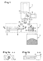
- Fig. 1 shows the device according to the invention in an embodiment for a Mixing head 1 with outlet pipe 12 and cleaning piston 11 with a substantially circular Cross-section.
- the cleaning piston 11 is at the end of the shot by means of hydraulic pistons 13 brought into a position in which it closes the outlet pipe 12.
- the known mixing head also has a mixing chamber 14, in the opposite Injection nozzles 15 for the main components polyol and isocyanate Polyurethane reactive mixture open.
- In the operating position shown after The end of the shot is the mixing chamber 14 through the locking piston 17 by means of hydraulic pistons 18 closed, so that the reactive components via grooves 19 with return lines 16 are connected.
- the cleaning device 2 consists of a Scraper plunger 21, which is perpendicular to the axis of the hydraulic piston 22 Cleaning piston 11 can be moved, and the mortar 23, which is a thrust surface 24 and has an outlet opening 25. Below the outlet opening 25 can a collecting container 3 can be provided for the residues ground in the mortar 23.
- Fig. 1b shows a view B-B of the scraper.
- Mortar 23 and the guide for the scraper plunger 21 are in a common frame, not shown held.
- Residues two half rings 27 and 28 may be provided, which are suitable, not Mechanics shown can be closed so that they include the outlet pipe.
- Figure 1a shows a view A-A of the wiper rings.
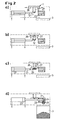
- the mixing head 1 is first after the shot brought into a position in which the outlet pipe 12 brings between the scraper 27 and 28 lies (phase a). Then the scraper half rings 27 and 28 are closed, so that they enclose the outlet pipe 12 (phase b). After that, the residues adhering laterally due to axial displacement of the scraper ring 27, 28 in the level of the outlet opening is promoted (phase c). Then through Actuation of the hydraulic piston 22 of the scraper plunger 21 with the scraper edge 26 guided along the underside of the cleaning piston, outlet pipe and scraper ring, the residues taken away and conveyed into the mortar 23 and at the Thrust edge 24 crushed and driven out through the opening 25.
- Fig. 3 shows the cleaning device according to the invention for a slit-shaped Outlet pipe 12 with a correspondingly shaped cleaning piston 11.
- the cleaning plunger 21 is adapted to the contour of the outlet pipe 12 (Fig. 3a).
- The is accordingly Mortar 23 opening shaped.
- Figure 3c shows view C-C of Figure 3b, i.e. the end face of the cleaning plunger 21. Otherwise, the same numerals designate comparable elements in the different figures.
Claims (5)
- Dispositif de protection sur des presses à imprimer comprenant un écran (10) de protection de forme plane qui est monté basculant par rapport à un axe (11) de basculement dans un bâti (G) de la presse et qui protège de l'accès par le personnel de service, une paire de cylindres comprenant un cylindre (1) porte-blanchet et un cylindre (2) porte-plaque, et après basculement, en s'éloignant de la paire (1, 2) de cylindre dégage l'accès à cette paire (1, 2) de cylindres
caractérisé en ce quea) il est prévu pour chaque paire (1, 2 ; 3, 4) de cylindres d'une tour d'impression ayant des éléments de pont en "U" et en "N" superposés en alternance respectivement un propre écran (10 ; 20) de protection etb) les axes (11 ; 21) de basculement des écrans (10 ; 20) de protection sont disposés dans la région de la tour d'impression délimitée par le pourtour extérieur des cylindres (2, 4) porte-plaque et à proximité de la ligne médiane imaginaire passant entre deux éléments de pont superposés de la tour d'impression. - Dispositif de protection suivant la revendication 1, caractérisé en ce qu'il est monté entre les paires de cylindres comprenant chacune un cylindre (1, 3) porte-blanchet et un cylindre (2, 4) porte-plaque de deux éléments de pont superposés dans la tour d'impression, un dispositif (30 ; 45) faisant écran.
- Dispositif de protection suivant la revendication 2, caractérisé en ce que le dispositif formant écran est formé par une surface(30) de séparation interposée de manière amovible entre deux cylindres porte-blanchet superposés.
- Dispositif de protection suivant la revendication 2, caractérisé en ce que le dispositif formant écran est formé par un dispositif (45) de lavage.
- Dispositif de protection suivant l'une des revendications précédentes, caractérisé en ce que les écrans (10, 20) de protection sont fixés sur des manivelles (13) de manière excentrée par rapport au palier de rotation des manivelles (13) et en faisant un angle avec la ligne imaginaire passant par les paliers de rotation des manivelles (13) et les axes (11, 21) de basculement.
Applications Claiming Priority (2)
| Application Number | Priority Date | Filing Date | Title |
|---|---|---|---|
| DE19716982A DE19716982A1 (de) | 1997-04-23 | 1997-04-23 | Vorrichtung zur Entfernung von Kunststoffrückständen von Mischkopf-Auslaufrohren |
| DE19716982 | 1997-04-23 |
Publications (2)
| Publication Number | Publication Date |
|---|---|
| EP0873836A1 EP0873836A1 (fr) | 1998-10-28 |
| EP0873836B1 true EP0873836B1 (fr) | 2001-03-14 |
Family
ID=7827392
Family Applications (1)
| Application Number | Title | Priority Date | Filing Date |
|---|---|---|---|
| EP98106763A Expired - Lifetime EP0873836B1 (fr) | 1997-04-23 | 1998-04-14 | Dispositif pour nettoyer d'orifices de décharge des mélangeurs |
Country Status (5)
| Country | Link |
|---|---|
| US (1) | US6033104A (fr) |
| EP (1) | EP0873836B1 (fr) |
| JP (1) | JPH10296721A (fr) |
| KR (1) | KR19980081613A (fr) |
| DE (2) | DE19716982A1 (fr) |
Families Citing this family (4)
| Publication number | Priority date | Publication date | Assignee | Title |
|---|---|---|---|---|
| DE102005007979A1 (de) * | 2005-02-22 | 2006-08-24 | Kraus-Maffei Kunststofftechnik Gmbh | Mischkopf für hochviskoses Ausgangsmaterial |
| US7566165B2 (en) * | 2006-04-17 | 2009-07-28 | Milliken & Company | Valved manifold and system suitable for introducing one or more additives into a fluid stream |
| DE102006054622B4 (de) * | 2006-11-17 | 2014-01-09 | Grammer Aktiengesellschaft | Vorrichtung zum Reinigen eines Mischkopfes einer Anlage zum Befüllen von Kunststoffformen |
| US8511047B2 (en) * | 2007-08-07 | 2013-08-20 | Sealed Air Corporation (Us) | Device for mixing and dispensing fluids |
Family Cites Families (9)
| Publication number | Priority date | Publication date | Assignee | Title |
|---|---|---|---|---|
| DE3111957A1 (de) * | 1981-03-26 | 1982-10-07 | Maschinenfabrik Hennecke Gmbh, 5090 Leverkusen | Einrichtung zum herstellen eines schaumstoff oder massivstoff bildenden fliessfaehigen reaktionsgemisches aus mindestens zwei fliessfaehigen komponenten |
| DE3231795A1 (de) * | 1982-08-26 | 1984-03-01 | Elastogran Maschinenbau GmbH, 2844 Lemförde | Verfahren zum entfernen von kunststoffrueckstaenden an mischvorrichtungen und formwerkzeugen |
| DE3521236A1 (de) * | 1985-06-13 | 1986-12-18 | IBW Ingenieur-Büro Woitzel GmbH, 4530 Ibbenbüren | Mischkopf zum vermischen zumindest zweier kunststoff bildender komponenten |
| DE8616880U1 (fr) * | 1986-06-25 | 1986-11-20 | Elastogran Maschinenbau Gmbh, 2844 Lemfoerde, De | |
| DE3626990A1 (de) * | 1986-08-08 | 1988-02-18 | Krauss Maffei Ag | Vorrichtung zum mischen von wenigstens zwei reaktiven kunststoffkomponenten |
| DE3907015A1 (de) * | 1989-03-04 | 1990-09-06 | Elastogran Polyurethane Gmbh | Vorrichtung zum mischen von mehrkomponenten-kunststoffen |
| DE4340559A1 (de) * | 1993-11-29 | 1995-06-01 | Hennecke Gmbh Maschf | Verfahren und Vorrichtung zur Entfernung von Kunststoffrückständen von Mischkopf-Auslaufrohren |
| DE4411901C2 (de) * | 1994-04-07 | 1997-03-27 | Bayerische Motoren Werke Ag | Abstreifvorrichtung für einen Mischkopf |
| DE19515039C2 (de) * | 1995-04-24 | 1998-10-01 | Krauss Maffei Ag | Vorrichtung zum Mischen von wenigstens zwei chemisch reaktiven Kunststoffkomponenten |
-
1997
- 1997-04-23 DE DE19716982A patent/DE19716982A1/de not_active Withdrawn
-
1998
- 1998-04-14 DE DE59800516T patent/DE59800516D1/de not_active Expired - Fee Related
- 1998-04-14 EP EP98106763A patent/EP0873836B1/fr not_active Expired - Lifetime
- 1998-04-15 US US09/060,714 patent/US6033104A/en not_active Expired - Fee Related
- 1998-04-20 JP JP10123875A patent/JPH10296721A/ja active Pending
- 1998-04-22 KR KR1019980014323A patent/KR19980081613A/ko not_active Application Discontinuation
Also Published As
| Publication number | Publication date |
|---|---|
| DE59800516D1 (de) | 2001-04-19 |
| JPH10296721A (ja) | 1998-11-10 |
| DE19716982A1 (de) | 1998-10-29 |
| EP0873836A1 (fr) | 1998-10-28 |
| KR19980081613A (ko) | 1998-11-25 |
| US6033104A (en) | 2000-03-07 |
Similar Documents
| Publication | Publication Date | Title |
|---|---|---|
| DE2407674A1 (de) | Fahrbare vorrichtung zum schleifen und reinigen von boeden | |
| EP0753387A1 (fr) | Procédé pour la fabrication de blocs de construction moulés | |
| EP0873836B1 (fr) | Dispositif pour nettoyer d'orifices de décharge des mélangeurs | |
| EP0603647B1 (fr) | Dispositif pour la fabrication en continu de bandes en mousse plastique, notamment de plaques de mousse à haute résistance | |
| DE2608437C2 (de) | Verfahren zum Verfestigen des Kantenbereiches einer Platte aus einem porösem Werkstoff mittels eines Verfestigungsmittels | |
| DE1467709B2 (fr) | ||
| DE4304489A1 (en) | Flow control valve for injection moulding machine - has valve head with central flow to outer edge of valve and onto front chamber walls | |
| DE3623935C1 (fr) | ||
| DE3444532A1 (de) | Verfahren und vorrichtung zum herstellen eines reissrandfreien formlings durch spritzgiessen, insbesondere von dichtscheiben aus gummi mit metalleinlage fuer waelzlager | |
| DE2942270C2 (de) | Entzunderungsanlage zum Entzundern von Warmband | |
| DE102006054622A1 (de) | Vorrichtung zum Reinigen eines Mischkopfes einer Anlage zum Befüllen von Kunststoffformen | |
| EP0532136B1 (fr) | Séparateur magnétique à chaînes | |
| DE2142979A1 (de) | Vorrichtung zum abtrennen des materials eines kraftfahrzeugreifens von der eingebetteten armierung und zum gleichzeitigen pulverisieren des materials | |
| DE3413648C1 (de) | Verfahren und Einrichtung zum Entfernen abgenutzter Gipseinlagen aus Preßformen für Dachziegel | |
| DE19535474C1 (de) | Vorrichtung zum Austragen eines aus chemisch reaktiven Kunststoffkomponenten gebildeten Kunststoffgemisches | |
| DE3119087A1 (de) | Strahlgeraet fuer feinmechanische werkstuecke, insbesondere gussteile in der dentaltechnik | |
| EP0361129A2 (fr) | Méthode et dispositif pour le nettoyage des bouteilles | |
| DE102005040966B4 (de) | Vorrichtung und Verfahren für die Behandlung und Handhabung von Zubehörteilen in einer Giesserei | |
| DE2305873A1 (de) | Vorrichtung zur kontinuierlichen herstellung von verbundprofilen aus metall und kunststoff | |
| DE4211803C2 (de) | Meißelartiges Abschälwerkzeug | |
| DE3807780A1 (de) | Anlage zum saeubern des fusses bzw. der unterseite keramischer produkte | |
| DE3338743C2 (de) | Vorrichtung zum Verdichten von körnigen Formstoffen | |
| DE4010963A1 (de) | Vorrichtung zur beseitigung von zunder und/oder schlacke an den oberflaechen eines metallgiessstranges | |
| DE2258451C3 (de) | Vorrichtung zum Anformen einer aus zwei Schichten bestehenden Sohle aus Gummi an das Oberteil eines Schuhes, Stiefels oder dgl | |
| DE4340559A1 (de) | Verfahren und Vorrichtung zur Entfernung von Kunststoffrückständen von Mischkopf-Auslaufrohren |
Legal Events
| Date | Code | Title | Description |
|---|---|---|---|
| PUAI | Public reference made under article 153(3) epc to a published international application that has entered the european phase |
Free format text: ORIGINAL CODE: 0009012 |
|
| AK | Designated contracting states |
Kind code of ref document: A1 Designated state(s): DE FR GB IT |
|
| AX | Request for extension of the european patent |
Free format text: AL;LT;LV;MK;RO;SI |
|
| 17P | Request for examination filed |
Effective date: 19990428 |
|
| AKX | Designation fees paid |
Free format text: DE FR GB IT |
|
| GRAG | Despatch of communication of intention to grant |
Free format text: ORIGINAL CODE: EPIDOS AGRA |
|
| RTI1 | Title (correction) |
Free format text: DEVICE FOR REMOVING SYNTHETIC MATERIAL RESIDUES FROM MIXHEAD OUTLETS |
|
| RTI1 | Title (correction) |
Free format text: DEVICE FOR REMOVING SYNTHETIC MATERIAL RESIDUES FROM MIXHEAD OUTLETS |
|
| 17Q | First examination report despatched |
Effective date: 20000427 |
|
| GRAG | Despatch of communication of intention to grant |
Free format text: ORIGINAL CODE: EPIDOS AGRA |
|
| GRAH | Despatch of communication of intention to grant a patent |
Free format text: ORIGINAL CODE: EPIDOS IGRA |
|
| GRAH | Despatch of communication of intention to grant a patent |
Free format text: ORIGINAL CODE: EPIDOS IGRA |
|
| GRAA | (expected) grant |
Free format text: ORIGINAL CODE: 0009210 |
|
| AK | Designated contracting states |
Kind code of ref document: B1 Designated state(s): DE FR GB IT |
|
| PGFP | Annual fee paid to national office [announced via postgrant information from national office to epo] |
Ref country code: DE Payment date: 20010317 Year of fee payment: 4 |
|
| GBT | Gb: translation of ep patent filed (gb section 77(6)(a)/1977) |
Effective date: 20010314 |
|
| PGFP | Annual fee paid to national office [announced via postgrant information from national office to epo] |
Ref country code: FR Payment date: 20010418 Year of fee payment: 4 |
|
| REF | Corresponds to: |
Ref document number: 59800516 Country of ref document: DE Date of ref document: 20010419 |
|
| ITF | It: translation for a ep patent filed |
Owner name: ING. C. GREGORJ S.P.A. |
|
| ET | Fr: translation filed | ||
| REG | Reference to a national code |
Ref country code: GB Ref legal event code: IF02 |
|
| PLBE | No opposition filed within time limit |
Free format text: ORIGINAL CODE: 0009261 |
|
| STAA | Information on the status of an ep patent application or granted ep patent |
Free format text: STATUS: NO OPPOSITION FILED WITHIN TIME LIMIT |
|
| 26N | No opposition filed | ||
| PG25 | Lapsed in a contracting state [announced via postgrant information from national office to epo] |
Ref country code: GB Free format text: LAPSE BECAUSE OF NON-PAYMENT OF DUE FEES Effective date: 20020414 |
|
| PG25 | Lapsed in a contracting state [announced via postgrant information from national office to epo] |
Ref country code: DE Free format text: LAPSE BECAUSE OF NON-PAYMENT OF DUE FEES Effective date: 20021101 |
|
| GBPC | Gb: european patent ceased through non-payment of renewal fee |
Effective date: 20020414 |
|
| PG25 | Lapsed in a contracting state [announced via postgrant information from national office to epo] |
Ref country code: FR Free format text: LAPSE BECAUSE OF NON-PAYMENT OF DUE FEES Effective date: 20021231 |
|
| REG | Reference to a national code |
Ref country code: FR Ref legal event code: ST |
|
| PG25 | Lapsed in a contracting state [announced via postgrant information from national office to epo] |
Ref country code: IT Free format text: LAPSE BECAUSE OF NON-PAYMENT OF DUE FEES Effective date: 20050414 |