EP0873836B1 - Device for removing synthetic material residues from mixhead outlets - Google Patents
Device for removing synthetic material residues from mixhead outlets Download PDFInfo
- Publication number
- EP0873836B1 EP0873836B1 EP98106763A EP98106763A EP0873836B1 EP 0873836 B1 EP0873836 B1 EP 0873836B1 EP 98106763 A EP98106763 A EP 98106763A EP 98106763 A EP98106763 A EP 98106763A EP 0873836 B1 EP0873836 B1 EP 0873836B1
- Authority
- EP
- European Patent Office
- Prior art keywords
- mortar
- stripping
- cleaning
- face
- ram
- Prior art date
- Legal status (The legal status is an assumption and is not a legal conclusion. Google has not performed a legal analysis and makes no representation as to the accuracy of the status listed.)
- Expired - Lifetime
Links
- 229920002994 synthetic fiber Polymers 0.000 title 1
- 238000004140 cleaning Methods 0.000 claims description 31
- 239000004570 mortar (masonry) Substances 0.000 claims description 22
- 239000004033 plastic Substances 0.000 claims description 11
- 229920003023 plastic Polymers 0.000 claims description 11
- 229920002635 polyurethane Polymers 0.000 claims description 6
- 239000004814 polyurethane Substances 0.000 claims description 6
- 238000002347 injection Methods 0.000 claims description 3
- 239000007924 injection Substances 0.000 claims description 3
- 230000002093 peripheral effect Effects 0.000 claims 1
- 239000000203 mixture Substances 0.000 description 3
- 238000006073 displacement reaction Methods 0.000 description 1
- 230000008020 evaporation Effects 0.000 description 1
- 238000001704 evaporation Methods 0.000 description 1
- 239000000945 filler Substances 0.000 description 1
- 238000005429 filling process Methods 0.000 description 1
- 239000012530 fluid Substances 0.000 description 1
- 239000007789 gas Substances 0.000 description 1
- 238000000227 grinding Methods 0.000 description 1
- 238000010438 heat treatment Methods 0.000 description 1
- 239000012948 isocyanate Substances 0.000 description 1
- 150000002513 isocyanates Chemical class 0.000 description 1
- 238000004519 manufacturing process Methods 0.000 description 1
- 238000000034 method Methods 0.000 description 1
- 229920005862 polyol Polymers 0.000 description 1
- 150000003077 polyols Chemical class 0.000 description 1
- 239000000243 solution Substances 0.000 description 1
Images

Classifications
-
- B—PERFORMING OPERATIONS; TRANSPORTING
- B29—WORKING OF PLASTICS; WORKING OF SUBSTANCES IN A PLASTIC STATE IN GENERAL
- B29B—PREPARATION OR PRETREATMENT OF THE MATERIAL TO BE SHAPED; MAKING GRANULES OR PREFORMS; RECOVERY OF PLASTICS OR OTHER CONSTITUENTS OF WASTE MATERIAL CONTAINING PLASTICS
- B29B7/00—Mixing; Kneading
- B29B7/80—Component parts, details or accessories; Auxiliary operations
- B29B7/802—Constructions or methods for cleaning the mixing or kneading device
-
- B—PERFORMING OPERATIONS; TRANSPORTING
- B29—WORKING OF PLASTICS; WORKING OF SUBSTANCES IN A PLASTIC STATE IN GENERAL
- B29B—PREPARATION OR PRETREATMENT OF THE MATERIAL TO BE SHAPED; MAKING GRANULES OR PREFORMS; RECOVERY OF PLASTICS OR OTHER CONSTITUENTS OF WASTE MATERIAL CONTAINING PLASTICS
- B29B7/00—Mixing; Kneading
- B29B7/74—Mixing; Kneading using other mixers or combinations of mixers, e.g. of dissimilar mixers ; Plant
- B29B7/76—Mixers with stream-impingement mixing head
- B29B7/7663—Mixers with stream-impingement mixing head the mixing head having an outlet tube with a reciprocating plunger, e.g. with the jets impinging in the tube
- B29B7/7684—Parts; Accessories
-
- B—PERFORMING OPERATIONS; TRANSPORTING
- B01—PHYSICAL OR CHEMICAL PROCESSES OR APPARATUS IN GENERAL
- B01F—MIXING, e.g. DISSOLVING, EMULSIFYING OR DISPERSING
- B01F35/00—Accessories for mixers; Auxiliary operations or auxiliary devices; Parts or details of general application
- B01F35/10—Maintenance of mixers
- B01F35/145—Washing or cleaning mixers not provided for in other groups in this subclass; Inhibiting build-up of material on machine parts using other means
-
- B—PERFORMING OPERATIONS; TRANSPORTING
- B29—WORKING OF PLASTICS; WORKING OF SUBSTANCES IN A PLASTIC STATE IN GENERAL
- B29B—PREPARATION OR PRETREATMENT OF THE MATERIAL TO BE SHAPED; MAKING GRANULES OR PREFORMS; RECOVERY OF PLASTICS OR OTHER CONSTITUENTS OF WASTE MATERIAL CONTAINING PLASTICS
- B29B7/00—Mixing; Kneading
- B29B7/80—Component parts, details or accessories; Auxiliary operations
- B29B7/802—Constructions or methods for cleaning the mixing or kneading device
- B29B7/803—Cleaning of mixers of the gun type, stream-impigement type, mixing heads
- B29B7/808—Cleaning of the plunger tip
-
- B—PERFORMING OPERATIONS; TRANSPORTING
- B29—WORKING OF PLASTICS; WORKING OF SUBSTANCES IN A PLASTIC STATE IN GENERAL
- B29B—PREPARATION OR PRETREATMENT OF THE MATERIAL TO BE SHAPED; MAKING GRANULES OR PREFORMS; RECOVERY OF PLASTICS OR OTHER CONSTITUENTS OF WASTE MATERIAL CONTAINING PLASTICS
- B29B7/00—Mixing; Kneading
- B29B7/80—Component parts, details or accessories; Auxiliary operations
- B29B7/88—Adding charges, i.e. additives
- B29B7/90—Fillers or reinforcements, e.g. fibres
-
- B—PERFORMING OPERATIONS; TRANSPORTING
- B29—WORKING OF PLASTICS; WORKING OF SUBSTANCES IN A PLASTIC STATE IN GENERAL
- B29K—INDEXING SCHEME ASSOCIATED WITH SUBCLASSES B29B, B29C OR B29D, RELATING TO MOULDING MATERIALS OR TO MATERIALS FOR MOULDS, REINFORCEMENTS, FILLERS OR PREFORMED PARTS, e.g. INSERTS
- B29K2275/00—Use of PU, i.e. polyureas or polyurethanes or derivatives thereof, as reinforcement
Definitions
- the present invention relates to a device for removing plastic residue, especially polyurethane residue, from the cleaning piston and outlet pipe a mixing head, in particular a countercurrent injection mixing head for Manufacture of reactive polyurethane mixtures.
- a device according to the preamble of claim 1 is known from the DE-A-43 40 559 which has been proposed, adhering to the side of the outlet pipe Residues first by means of a scraper ring in the outlet level of the outlet pipe to push and then using a cleaning belt running over rollers from the outlet pipe and cleaning piston.
- the removal of Residue after this suggestion is problematic if it is before removal of the residue to a substantial hardening of the polyurethane reactive mixture is coming.
- the object of the present invention is that the device according to the characterizing part of claim 1 a scraper, a mortar to hold the scraper with an angle to the impact surface of the mortar arranged outlet opening for the plastic residue, means for Moving the mixing head and scraper to each other in the cleaning position, in the the scraper edge of the scraper with the end face of the cleaning piston is aligned, with the axis of the cleaning piston between mortar and scraper lies, and means for moving the scraper parallel to the end face of the Has cleaning pistons in the mortar and against the abutment surface of the mortar.
- the scraper With the scraper, firmly adhering and possibly already hardened plastic residues can be safely removed from the end face of the cleaning piston and the mixing head outlet pipe.
- the plastic residues are then conveyed with the scraper into a mortar adapted to the cross-sectional shape of the pestle, where they are pounded against the mortar face and ground.
- the ground plastic residues fall into a collecting and collecting container through an outlet opening provided in the mortar and aligned with its abutting surface. They can then be recycled.
- the scraper is preferably moved by means of a hydraulic system and pushed into the mortar, the hydraulic fluid being able to have a pressure of 150 to 180 bar.
- a surface force of 10 to 500 N / mm 2 can be exerted on the mortar joint surface, which is sufficient for grinding even hardened polyurethane residues, even if they contain fillers.
- the surface force is preferably between 30 and 100 N / mm 2 .
- an additional Scraper ring should be provided, the the adhering residues in front of the Wiping by means of a scraper into the plane of the outlet opening.
- the Scraper ring can, as shown in DE-A 43 40 559, Fig. 6, with the mixing head be connected, or be connected to the cleaning device, wherein in in the latter case the scraper ring is designed to be divisible and by moving the mixing head is closed in the cleaning position so that he the outlet pipe encloses.
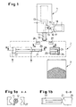
- Fig. 1 shows the device according to the invention in an embodiment for a Mixing head 1 with outlet pipe 12 and cleaning piston 11 with a substantially circular Cross-section.
- the cleaning piston 11 is at the end of the shot by means of hydraulic pistons 13 brought into a position in which it closes the outlet pipe 12.
- the known mixing head also has a mixing chamber 14, in the opposite Injection nozzles 15 for the main components polyol and isocyanate Polyurethane reactive mixture open.
- In the operating position shown after The end of the shot is the mixing chamber 14 through the locking piston 17 by means of hydraulic pistons 18 closed, so that the reactive components via grooves 19 with return lines 16 are connected.
- the cleaning device 2 consists of a Scraper plunger 21, which is perpendicular to the axis of the hydraulic piston 22 Cleaning piston 11 can be moved, and the mortar 23, which is a thrust surface 24 and has an outlet opening 25. Below the outlet opening 25 can a collecting container 3 can be provided for the residues ground in the mortar 23.
- Fig. 1b shows a view B-B of the scraper.
- Mortar 23 and the guide for the scraper plunger 21 are in a common frame, not shown held.
- Residues two half rings 27 and 28 may be provided, which are suitable, not Mechanics shown can be closed so that they include the outlet pipe.
- Figure 1a shows a view A-A of the wiper rings.
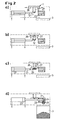
- the mixing head 1 is first after the shot brought into a position in which the outlet pipe 12 brings between the scraper 27 and 28 lies (phase a). Then the scraper half rings 27 and 28 are closed, so that they enclose the outlet pipe 12 (phase b). After that, the residues adhering laterally due to axial displacement of the scraper ring 27, 28 in the level of the outlet opening is promoted (phase c). Then through Actuation of the hydraulic piston 22 of the scraper plunger 21 with the scraper edge 26 guided along the underside of the cleaning piston, outlet pipe and scraper ring, the residues taken away and conveyed into the mortar 23 and at the Thrust edge 24 crushed and driven out through the opening 25.
- Fig. 3 shows the cleaning device according to the invention for a slit-shaped Outlet pipe 12 with a correspondingly shaped cleaning piston 11.
- the cleaning plunger 21 is adapted to the contour of the outlet pipe 12 (Fig. 3a).
- The is accordingly Mortar 23 opening shaped.
- Figure 3c shows view C-C of Figure 3b, i.e. the end face of the cleaning plunger 21. Otherwise, the same numerals designate comparable elements in the different figures.
Description
Die vorliegende Erfindung betrifft eine Vorrichtung zur Entfernung von Kunststoffrückstand, insbesondere Polyurethanrückstand, vom Reinigungskolben und Auslaufrohr eines Mischkopfes, insbesondere eines Gegenstrominjektionsmischkopfes zur Herstellung von Polyurethan-Reaktivmischungen.The present invention relates to a device for removing plastic residue, especially polyurethane residue, from the cleaning piston and outlet pipe a mixing head, in particular a countercurrent injection mixing head for Manufacture of reactive polyurethane mixtures.
Das der vorliegenden Erfindung zugrundeliegende Problem wird bereits in der EP-A-0 101 988 behandelt. Danach wird vorgeschlagen, das Auslaufrohr und den Reinigungskolben nach jeder Befüllung einer Form (Schuß) zu erhitzen, so daß der Kunststoffrückstand, der nach Befüllung der Form am Auslaufrohr und Reinigungskolben haften geblieben ist, verdampft. Die in der EP-A-0 101 988 vorgeschlagene Lösung ist jedoch bei schnellem Arbeitszyklus, d.h. bei hoher Schußfolge, wegen der Trägheit der Erhitzung nicht oder nur mit großem Aufwand anwendbar. Zum Beispiel werden bei den heute weitgehend automatisierten Formfüllvorgängen Kunststoff-Formen mit Taktzeiten von 10 bis 30 Sekunden gefüllt. Ferner entsteht das Problem, die bei der Verdampfung der Kunststoffrückstände entstehenden Gase sicher aufzufangen und zu entsorgen.The problem underlying the present invention is already in the EP-A-0 101 988 treated. Then it is proposed the outlet pipe and the Heat the cleaning flask after filling a mold (shot) so that the Plastic residue, which after filling the mold on the outlet pipe and cleaning piston stuck, evaporated. The one proposed in EP-A-0 101 988 However, the solution is for a fast work cycle, i.e. with a high shot sequence, because of the Inertia of the heating cannot be used or can only be used with great effort. For example plastic molds are used in today's largely automated mold filling processes filled with cycle times of 10 to 30 seconds. Furthermore, the problem arises to safely collect the gases generated during the evaporation of the plastic residues and dispose of.
Eine Vorrichtung gemäß dem Oberbegriff des Anspruchs 1 ist bekannt aus dem DE-A-43 40 559 wonach vorgeschlagen wurde, seitlich am Auslaufrohr anhaftende Rückstände zunächst mittels eines Abstreifringes in die Auslaufebene des Auslaufrohres zu schieben und anschließend mittels eines über Walzen laufenden Reinigungsbandes vom Auslaufrohr und Reinigungskolben abzunehmen. Die Entfernung von Rückständen nach diesem Vorschlag ist dann problematisch, wenn es vor der Entfernung des Rückstands bereits zu einer wesentlichen Aushärtung der Polyurethanreaktivmischung kommt.A device according to the preamble of claim 1 is known from the DE-A-43 40 559 which has been proposed, adhering to the side of the outlet pipe Residues first by means of a scraper ring in the outlet level of the outlet pipe to push and then using a cleaning belt running over rollers from the outlet pipe and cleaning piston. The removal of Residue after this suggestion is problematic if it is before removal of the residue to a substantial hardening of the polyurethane reactive mixture is coming.
Gegenstand der vorliegenden Erfindung ist, daß die Vorrichtung gemäß dem kennzeichnenden Teil des Anspruchs 1 einen Abstreifstößel, einen Mörser zur Aufnahme des Abstreifstößels mit einer im Winkel zu der Stoßfläche des Mörsers angeordneten Auslaßöffhung für den Kunststoffrückstand, Mittel zur Verbringung von Mischkopf und Abstreifstößel in Reinigungsstellung zueinander, in der die Abstreifkante des Abstreifstößels mit der Stirnfläche des Reinigungskolbens fluchtet, wobei die Achse des Reinigungskolbens zwischen Mörser und Abstreifstößel liegt, und Mittel zur Bewegung des Abstreifstößels parallel zur Stirnfläche des Reinigungskolbens in den Mörser und gegen die Stoßfläche des Mörsers aufweist.The object of the present invention is that the device according to the characterizing part of claim 1 a scraper, a mortar to hold the scraper with an angle to the impact surface of the mortar arranged outlet opening for the plastic residue, means for Moving the mixing head and scraper to each other in the cleaning position, in the the scraper edge of the scraper with the end face of the cleaning piston is aligned, with the axis of the cleaning piston between mortar and scraper lies, and means for moving the scraper parallel to the end face of the Has cleaning pistons in the mortar and against the abutment surface of the mortar.
Mit dem Abstreifstößel können auch fest anhaftende und gegebenenfalls bereits ausgehärtete Kunststoffrückstände sicher von der Stirnfläche des Reinigungskolbens und des Mischkopfauslaufrohres entfernt werden. Die Kunststoffrückstände werden anschließend mit dem Abstreifstößel in einen der Querschnittsform des Stößels angepaßten Mörser gefördert und dort gegen die Stoßfläche des Mörsers gestampft und dabei zermahlen. Die zermahlenen Kunststoffrückstände fallen durch eine im Mörser vorgesehene, mit dessen Stoßfläche fluchtende Auslaßöffnung in einen Auffang- und Sammelbehälter. Sie können anschließend recycled werden. Vorzugsweise wird der Abstreifstößel mittels einer Hydraulik bewegt und in den Mörser hineingestoßen, wobei die Hydraulikflüssigkeit einen Druck von 150 bis 180 bar aufweisen kann. Durch entsprechende Querschnittsgestaltung von Abstreifstößel und Hydraulikkolben kann auf die Stoßfläche des Mörsers eine Flächenkraft von 10 bis 500 N/mm2 ausgeübt werden, die für die Zermahlung auch ausgehärteter Polyurethanrückstände, selbst wenn diese Füllstoffe enthalten, ausreichen. Bevorzugt liegt die Flächenkraft zwischen 30 und 100 N/mm2.With the scraper, firmly adhering and possibly already hardened plastic residues can be safely removed from the end face of the cleaning piston and the mixing head outlet pipe. The plastic residues are then conveyed with the scraper into a mortar adapted to the cross-sectional shape of the pestle, where they are pounded against the mortar face and ground. The ground plastic residues fall into a collecting and collecting container through an outlet opening provided in the mortar and aligned with its abutting surface. They can then be recycled. The scraper is preferably moved by means of a hydraulic system and pushed into the mortar, the hydraulic fluid being able to have a pressure of 150 to 180 bar. With a corresponding cross-sectional design of the scraper and hydraulic piston, a surface force of 10 to 500 N / mm 2 can be exerted on the mortar joint surface, which is sufficient for grinding even hardened polyurethane residues, even if they contain fillers. The surface force is preferably between 30 and 100 N / mm 2 .
Zur Entfernung seitlich am Auslaufrohr anhaftender Rückstände kann zusätzlich ein Abstreifring vorgesehen sein, der die seitlich anhaftenden Rückstände vor der Abstreifung mittels Abstreifstößel in die Ebene der Auslauföffnung fördert. Der Abstreifring kann, wie in DE-A 43 40 559, Fig. 6 dargestellt, mit dem Mischkopf verbunden sein, oder mit der Reinigungsvorrichtung verbunden sein, wobei im letzteren Fall der Abstreifring teilbar ausgebildet ist und nach Verfahren des Mischkopfes in die Reinigungsstellung geschlossen wird, so daß er das Auslaufrohr umschließt. To remove residues adhering to the side of the outlet pipe, an additional Scraper ring should be provided, the the adhering residues in front of the Wiping by means of a scraper into the plane of the outlet opening. The Scraper ring can, as shown in DE-A 43 40 559, Fig. 6, with the mixing head be connected, or be connected to the cleaning device, wherein in in the latter case the scraper ring is designed to be divisible and by moving the mixing head is closed in the cleaning position so that he the outlet pipe encloses.
Die Erfindung wird nachfolgend anhand der Figuren 1 bis 3 näher erläutert.The invention is explained in more detail below with reference to FIGS. 1 to 3.
Fig. 1 zeigt die erfindungsgemäße Vorrichtung in einer Ausbildung für einen
Mischkopf 1 mit Auslaufrohr 12 und Reinigungskolben 11 mit im wesentlichem kreisrundem
Querschnitt. Der Reinigungskolben 11 ist nach Schußende mittels Hydraulikkolben
13 in eine Position gebracht, in der dieser das Auslaufrohr 12 verschließt. Der
an sich bekannte Mischkopf weist ferner eine Mischkammer 14 auf, in die gegenüberliegende
Injektionsdüsen 15 für die Hauptkomponenten Polyol und Isocyanat der
Polyurethanreaktivmischung münden. In der dargestellten Betriebsstellung nach
Schußende ist die Mischkammer 14 durch den Verschlußkolben 17 mittels Hydraulikkolben
18 verschlossen, so daß die Reaktivkomponenten über Nuten 19 mit Rückführleitungen
16 verbunden sind. Die Reinigungsvorrichtung 2 besteht aus einem
Abstreifstößel 21, der mittels Hydraulikkolben 22 senkrecht zur Achse des
Reinigungskolbens 11 bewegt werden kann, sowie dem Mörser 23, der eine Stoßfläche
24 und eine Auslaßöffhung 25 aufweist. Unterhalb der Auslaßöffhung 25 kann
ein Auffangbehälter 3 für die im Mörser 23 zermahlenen Rückstände vorgesehen sein.Fig. 1 shows the device according to the invention in an embodiment for a
Mixing head 1 with
Fig. 1b zeigt eine Ansicht B-B des Abstreifstößels. Mörser 23 und die Führung für
den Abstreifstößel 21 sind in einem gemeinsamen nicht dargestellten Rahmen
gehalten. Ferner können zur Entfernung seitlich am Auslaufrohr 12 anhaftende
Rückstände zwei Halbringe 27 und 28 vorgesehen sein, die über eine geeignete, nicht
dargestellte Mechanik geschlossen werden können, so daß sie das Auslaufrohr umfassen.Fig. 1b shows a view B-B of the scraper. Mortar 23 and the guide for
the
Fig. 1a zeigt eine Ansicht A-A der Abstreifringe.Figure 1a shows a view A-A of the wiper rings.
Fig. 2 zeigt verschiedene Phasen des Reinigungsvorgangs.2 shows different phases of the cleaning process.
Bei ortsfester Reinigungsvorrichtung wird zunächst der Mischkopf 1 nach dem Schuß
in eine Position gebracht, in der das Auslaufrohr 12 zwischen den Abstreifhalbringen
27 und 28 liegt (Phase a). Anschließend werden die Abstreifhalbringe 27 und 28 geschlossen,
so daß sie das Auslaufrohr 12 umschließen (Phase b). Danach werden die
seitlich anhaftenden Rückstände durch axiale Verschiebung des Abstreifrings 27, 28 in
die Ebene der Auslauföffnung gefördert (Phase c). Anschließend wird durch
Betätigung des Hydraulikkolbens 22 der Abstreifstößel 21 mit der Abstreifkante 26 an
der Unterseite von Reinigungskolben, Auslaufrohr und Abstreifring entlanggeführt,
wobei die Rückstände mitgenommen und in den Mörser 23 gefördert sowie an der
Stoßkante 24 zerkleinert und durch die Öffnung 25 ausgetrieben werden.In the case of a stationary cleaning device, the mixing head 1 is first after the shot
brought into a position in which the
Fig. 3 zeigt die erfindungsgemäße Reinigungsvorrichtung für ein schlitzförmiges
Auslaufrohr 12 mit entsprechend geformtem Reinigungskolben 11. Der Reinigungsstößel
21 ist der Kontur des Auslaufrohres 12 (Fig. 3a) angepaßt. Entsprechend ist die
Öffnung des Mörsers 23 geformt.Fig. 3 shows the cleaning device according to the invention for a slit-
Fig. 3c stellt die Ansicht C-C aus Fig. 3b dar, d.h. die Stirnfläche des Reinigungsstößels
21. Im übrigen bezeichnen gleiche Ziffern vergleichbare Elemente in den
unterschiedlichen Figuren.Figure 3c shows view C-C of Figure 3b, i.e. the end face of the
Claims (5)
- Device for removing plastic residue, in particular polyurethane residue, from the cleaning piston (11) and mixing-head discharge tube (12) of, in particular, a countercurrent-injection mixing head (1),
characterised in that the said device has a stripping ram (21); a mortar (23) for receiving the stripping ram (21), the said mortar having an outlet aperture (25) for the plastic residue, which outlet aperture is disposed at an angle to the impact face (24) of the said mortar (23); means for bringing the mixing head and stripping ram towards one another into a cleaning position in which the stripping edge (26) of the stripping ram (21) is in alignment with the end face of the cleaning piston (11), the axis of the said cleaning piston (11) being located between the mortar (23) and the stripping ram (21); and means (22) for moving the stripping ram, parallel to the end face of the cleaning piston (11), into the mortar (23) and against the impact face (24) of the latter. - Device according to claim 1, wherein the end face of the cleaning piston (11) is in alignment, when in the cleaning position, with the outlet of the discharge tube (12).
- Device according to claim 2, wherein a divisible stripping ring (27, 28) for the peripheral face of the discharge tube (12) is additionally provided, which stripping ring can be closed when in the cleaning position and is capable of travelling, in the axial direction of the tube, into a position in which it is in alignment with the stripping edge (26) of the stripping ram (21).
- Device according to one of claims 1 to 3, wherein the stripping ram (21) exerts a force of 10 to 500 N/mm2 on the impact face (24) of the mortar (23).
- Device according to one of claims 1 to 4, wherein a collecting container (3) for the plastic residues is disposed underneath the outlet aperture (25) of the mortar (23).
Applications Claiming Priority (2)
| Application Number | Priority Date | Filing Date | Title |
|---|---|---|---|
| DE19716982A DE19716982A1 (en) | 1997-04-23 | 1997-04-23 | Device for removing plastic residues from mixing head outlet pipes |
| DE19716982 | 1997-04-23 |
Publications (2)
| Publication Number | Publication Date |
|---|---|
| EP0873836A1 EP0873836A1 (en) | 1998-10-28 |
| EP0873836B1 true EP0873836B1 (en) | 2001-03-14 |
Family
ID=7827392
Family Applications (1)
| Application Number | Title | Priority Date | Filing Date |
|---|---|---|---|
| EP98106763A Expired - Lifetime EP0873836B1 (en) | 1997-04-23 | 1998-04-14 | Device for removing synthetic material residues from mixhead outlets |
Country Status (5)
| Country | Link |
|---|---|
| US (1) | US6033104A (en) |
| EP (1) | EP0873836B1 (en) |
| JP (1) | JPH10296721A (en) |
| KR (1) | KR19980081613A (en) |
| DE (2) | DE19716982A1 (en) |
Families Citing this family (4)
| Publication number | Priority date | Publication date | Assignee | Title |
|---|---|---|---|---|
| DE102005007979A1 (en) * | 2005-02-22 | 2006-08-24 | Kraus-Maffei Kunststofftechnik Gmbh | Mixing head for reaction injection molding process has high viscosity material recirculating valve which switches to feed mixing chamber and low viscosity component injection is between feed channel and mixing chamber |
| US7566165B2 (en) * | 2006-04-17 | 2009-07-28 | Milliken & Company | Valved manifold and system suitable for introducing one or more additives into a fluid stream |
| DE102006054622B4 (en) * | 2006-11-17 | 2014-01-09 | Grammer Aktiengesellschaft | Device for cleaning a mixing head of a plant for filling plastic molds |
| US8511047B2 (en) * | 2007-08-07 | 2013-08-20 | Sealed Air Corporation (Us) | Device for mixing and dispensing fluids |
Family Cites Families (9)
| Publication number | Priority date | Publication date | Assignee | Title |
|---|---|---|---|---|
| DE3111957A1 (en) * | 1981-03-26 | 1982-10-07 | Maschinenfabrik Hennecke Gmbh, 5090 Leverkusen | DEVICE FOR PRODUCING A FOAM OR SOLID-FLOWABLE REACTION MIXTURE FROM AT LEAST TWO FLOWABLE COMPONENTS |
| DE3231795A1 (en) * | 1982-08-26 | 1984-03-01 | Elastogran Maschinenbau GmbH, 2844 Lemförde | METHOD FOR REMOVING PLASTIC RESIDUES FROM MIXING DEVICES AND MOLDING TOOLS |
| DE3521236A1 (en) * | 1985-06-13 | 1986-12-18 | IBW Ingenieur-Büro Woitzel GmbH, 4530 Ibbenbüren | MIXING HEAD FOR MIXING AT LEAST TWO PLASTIC COMPONENTS |
| DE8616880U1 (en) * | 1986-06-25 | 1986-11-20 | Elastogran Maschinenbau Gmbh, 2844 Lemfoerde, De | |
| DE3626990A1 (en) * | 1986-08-08 | 1988-02-18 | Krauss Maffei Ag | DEVICE FOR MIXING AT LEAST TWO REACTIVE PLASTIC COMPONENTS |
| DE3907015A1 (en) * | 1989-03-04 | 1990-09-06 | Elastogran Polyurethane Gmbh | Apparatus for mixing multi-component plastics |
| DE4340559A1 (en) * | 1993-11-29 | 1995-06-01 | Hennecke Gmbh Maschf | Removal of hardening plastic resin |
| DE4411901C2 (en) * | 1994-04-07 | 1997-03-27 | Bayerische Motoren Werke Ag | Scraper for a mixing head |
| DE19515039C2 (en) * | 1995-04-24 | 1998-10-01 | Krauss Maffei Ag | Device for mixing at least two chemically reactive plastic components |
-
1997
- 1997-04-23 DE DE19716982A patent/DE19716982A1/en not_active Withdrawn
-
1998
- 1998-04-14 EP EP98106763A patent/EP0873836B1/en not_active Expired - Lifetime
- 1998-04-14 DE DE59800516T patent/DE59800516D1/en not_active Expired - Fee Related
- 1998-04-15 US US09/060,714 patent/US6033104A/en not_active Expired - Fee Related
- 1998-04-20 JP JP10123875A patent/JPH10296721A/en active Pending
- 1998-04-22 KR KR1019980014323A patent/KR19980081613A/en not_active Application Discontinuation
Also Published As
| Publication number | Publication date |
|---|---|
| DE59800516D1 (en) | 2001-04-19 |
| EP0873836A1 (en) | 1998-10-28 |
| JPH10296721A (en) | 1998-11-10 |
| DE19716982A1 (en) | 1998-10-29 |
| US6033104A (en) | 2000-03-07 |
| KR19980081613A (en) | 1998-11-25 |
Similar Documents
| Publication | Publication Date | Title |
|---|---|---|
| DE2407674A1 (en) | MOBILE DEVICE FOR GRINDING AND CLEANING FLOORS | |
| EP0873836B1 (en) | Device for removing synthetic material residues from mixhead outlets | |
| EP0603647B1 (en) | Apparatus for the continuous production of foam sheets, particularly hard foam panels | |
| DE2608437C2 (en) | Method for consolidating the edge area of a plate made of a porous material by means of a consolidating agent | |
| DE1467709B2 (en) | ||
| DE102006054622B4 (en) | Device for cleaning a mixing head of a plant for filling plastic molds | |
| DE3623935C1 (en) | ||
| DE3444532A1 (en) | Process and device for producing a flashface-free moulding by injection moulding, in particular of rubber gaskets with metal inserts for roller bearings | |
| DE2942270C2 (en) | Descaling plant for descaling hot strip | |
| EP0532136B1 (en) | Magnetic separator with chains | |
| DE2142979A1 (en) | DEVICE FOR SEPARATING THE MATERIAL OF A MOTOR VEHICLE TIRE FROM THE EMBEDDED REINFORCEMENT AND AT THE SAME TIME PULVERIZING THE MATERIAL | |
| DE3413648C1 (en) | Process and device for removing worn gypsum inserts from press moulds for roof tiles | |
| DE19535474C1 (en) | Equipment to clean e.g. polyurethane foam-forming droplets from nozzles | |
| DE3119087A1 (en) | Abrasive-blasting unit for precision-mechanical workpieces, in particular castings in dental technology | |
| EP0361129A2 (en) | Method and device for cleaning bottles | |
| DE102005040966B4 (en) | Apparatus and method for handling and handling accessories in a foundry | |
| DE2305873A1 (en) | Endless belt mould for polyurethane foam - with laterally closed moulds to resist foaming pressure | |
| DE4211803C2 (en) | Chisel-like peeling tool | |
| DE3807780A1 (en) | Installation for cleaning the foot or the underside of ceramic products | |
| DE3338743C2 (en) | Device for compacting granular molding materials | |
| DE4010963A1 (en) | Continuous cast metal cleaner - has scrapers on both sides of metal under the die to detach scale and slag | |
| DE2828534A1 (en) | METHOD AND DEVICE FOR CUTTING BRICK FORMS FROM A TONE STRING | |
| DE2258451C3 (en) | Device for molding a rubber sole consisting of two layers onto the upper part of a shoe, boot or the like | |
| DE102021108088A1 (en) | Device and method for cleaning a mixing head and reaction casting system | |
| DE4340559A1 (en) | Removal of hardening plastic resin |
Legal Events
| Date | Code | Title | Description |
|---|---|---|---|
| PUAI | Public reference made under article 153(3) epc to a published international application that has entered the european phase |
Free format text: ORIGINAL CODE: 0009012 |
|
| AK | Designated contracting states |
Kind code of ref document: A1 Designated state(s): DE FR GB IT |
|
| AX | Request for extension of the european patent |
Free format text: AL;LT;LV;MK;RO;SI |
|
| 17P | Request for examination filed |
Effective date: 19990428 |
|
| AKX | Designation fees paid |
Free format text: DE FR GB IT |
|
| GRAG | Despatch of communication of intention to grant |
Free format text: ORIGINAL CODE: EPIDOS AGRA |
|
| RTI1 | Title (correction) |
Free format text: DEVICE FOR REMOVING SYNTHETIC MATERIAL RESIDUES FROM MIXHEAD OUTLETS |
|
| RTI1 | Title (correction) |
Free format text: DEVICE FOR REMOVING SYNTHETIC MATERIAL RESIDUES FROM MIXHEAD OUTLETS |
|
| 17Q | First examination report despatched |
Effective date: 20000427 |
|
| GRAG | Despatch of communication of intention to grant |
Free format text: ORIGINAL CODE: EPIDOS AGRA |
|
| GRAH | Despatch of communication of intention to grant a patent |
Free format text: ORIGINAL CODE: EPIDOS IGRA |
|
| GRAH | Despatch of communication of intention to grant a patent |
Free format text: ORIGINAL CODE: EPIDOS IGRA |
|
| GRAA | (expected) grant |
Free format text: ORIGINAL CODE: 0009210 |
|
| AK | Designated contracting states |
Kind code of ref document: B1 Designated state(s): DE FR GB IT |
|
| PGFP | Annual fee paid to national office [announced via postgrant information from national office to epo] |
Ref country code: DE Payment date: 20010317 Year of fee payment: 4 |
|
| GBT | Gb: translation of ep patent filed (gb section 77(6)(a)/1977) |
Effective date: 20010314 |
|
| PGFP | Annual fee paid to national office [announced via postgrant information from national office to epo] |
Ref country code: FR Payment date: 20010418 Year of fee payment: 4 |
|
| REF | Corresponds to: |
Ref document number: 59800516 Country of ref document: DE Date of ref document: 20010419 |
|
| ITF | It: translation for a ep patent filed |
Owner name: ING. C. GREGORJ S.P.A. |
|
| ET | Fr: translation filed | ||
| REG | Reference to a national code |
Ref country code: GB Ref legal event code: IF02 |
|
| PLBE | No opposition filed within time limit |
Free format text: ORIGINAL CODE: 0009261 |
|
| STAA | Information on the status of an ep patent application or granted ep patent |
Free format text: STATUS: NO OPPOSITION FILED WITHIN TIME LIMIT |
|
| 26N | No opposition filed | ||
| PG25 | Lapsed in a contracting state [announced via postgrant information from national office to epo] |
Ref country code: GB Free format text: LAPSE BECAUSE OF NON-PAYMENT OF DUE FEES Effective date: 20020414 |
|
| PG25 | Lapsed in a contracting state [announced via postgrant information from national office to epo] |
Ref country code: DE Free format text: LAPSE BECAUSE OF NON-PAYMENT OF DUE FEES Effective date: 20021101 |
|
| GBPC | Gb: european patent ceased through non-payment of renewal fee |
Effective date: 20020414 |
|
| PG25 | Lapsed in a contracting state [announced via postgrant information from national office to epo] |
Ref country code: FR Free format text: LAPSE BECAUSE OF NON-PAYMENT OF DUE FEES Effective date: 20021231 |
|
| REG | Reference to a national code |
Ref country code: FR Ref legal event code: ST |
|
| PG25 | Lapsed in a contracting state [announced via postgrant information from national office to epo] |
Ref country code: IT Free format text: LAPSE BECAUSE OF NON-PAYMENT OF DUE FEES Effective date: 20050414 |