EP0861368B1 - Kühlkreislauf einer brennkraftmaschine sowie verfahren zum betrieb des kühlkreislaufes - Google Patents
Kühlkreislauf einer brennkraftmaschine sowie verfahren zum betrieb des kühlkreislaufes Download PDFInfo
- Publication number
- EP0861368B1 EP0861368B1 EP97940120A EP97940120A EP0861368B1 EP 0861368 B1 EP0861368 B1 EP 0861368B1 EP 97940120 A EP97940120 A EP 97940120A EP 97940120 A EP97940120 A EP 97940120A EP 0861368 B1 EP0861368 B1 EP 0861368B1
- Authority
- EP
- European Patent Office
- Prior art keywords
- coolant
- temperature
- cooling circuit
- heat exchanger
- cooling
- Prior art date
- Legal status (The legal status is an assumption and is not a legal conclusion. Google has not performed a legal analysis and makes no representation as to the accuracy of the status listed.)
- Expired - Lifetime
Links
- 238000001816 cooling Methods 0.000 title claims description 69
- 238000002485 combustion reaction Methods 0.000 title claims description 18
- 238000000034 method Methods 0.000 title claims description 10
- 239000002826 coolant Substances 0.000 claims description 110
- 230000005540 biological transmission Effects 0.000 claims description 11
- 239000000446 fuel Substances 0.000 claims description 3
- 238000006243 chemical reaction Methods 0.000 claims 2
- 238000001746 injection moulding Methods 0.000 claims 2
- 239000000284 extract Substances 0.000 claims 1
- 230000002093 peripheral effect Effects 0.000 claims 1
- 230000000630 rising effect Effects 0.000 claims 1
- 239000003921 oil Substances 0.000 description 34
- XLYOFNOQVPJJNP-UHFFFAOYSA-N water Substances O XLYOFNOQVPJJNP-UHFFFAOYSA-N 0.000 description 20
- 238000010438 heat treatment Methods 0.000 description 8
- 239000012208 gear oil Substances 0.000 description 5
- 239000000498 cooling water Substances 0.000 description 4
- 238000010586 diagram Methods 0.000 description 4
- 238000002347 injection Methods 0.000 description 4
- 239000007924 injection Substances 0.000 description 4
- 238000005192 partition Methods 0.000 description 4
- 230000007704 transition Effects 0.000 description 4
- 239000000243 solution Substances 0.000 description 3
- 230000002411 adverse Effects 0.000 description 1
- 230000000694 effects Effects 0.000 description 1
- 230000002349 favourable effect Effects 0.000 description 1
- 239000000463 material Substances 0.000 description 1
- 230000001105 regulatory effect Effects 0.000 description 1
- 238000000926 separation method Methods 0.000 description 1
Images


Classifications
-
- F—MECHANICAL ENGINEERING; LIGHTING; HEATING; WEAPONS; BLASTING
- F01—MACHINES OR ENGINES IN GENERAL; ENGINE PLANTS IN GENERAL; STEAM ENGINES
- F01P—COOLING OF MACHINES OR ENGINES IN GENERAL; COOLING OF INTERNAL-COMBUSTION ENGINES
- F01P3/00—Liquid cooling
- F01P3/20—Cooling circuits not specific to a single part of engine or machine
-
- F—MECHANICAL ENGINEERING; LIGHTING; HEATING; WEAPONS; BLASTING
- F01—MACHINES OR ENGINES IN GENERAL; ENGINE PLANTS IN GENERAL; STEAM ENGINES
- F01P—COOLING OF MACHINES OR ENGINES IN GENERAL; COOLING OF INTERNAL-COMBUSTION ENGINES
- F01P11/00—Component parts, details, or accessories not provided for in, or of interest apart from, groups F01P1/00 - F01P9/00
- F01P11/02—Liquid-coolant filling, overflow, venting, or draining devices
- F01P11/029—Expansion reservoirs
-
- F—MECHANICAL ENGINEERING; LIGHTING; HEATING; WEAPONS; BLASTING
- F01—MACHINES OR ENGINES IN GENERAL; ENGINE PLANTS IN GENERAL; STEAM ENGINES
- F01P—COOLING OF MACHINES OR ENGINES IN GENERAL; COOLING OF INTERNAL-COMBUSTION ENGINES
- F01P7/00—Controlling of coolant flow
- F01P7/14—Controlling of coolant flow the coolant being liquid
- F01P7/16—Controlling of coolant flow the coolant being liquid by thermostatic control
- F01P7/165—Controlling of coolant flow the coolant being liquid by thermostatic control characterised by systems with two or more loops
-
- F—MECHANICAL ENGINEERING; LIGHTING; HEATING; WEAPONS; BLASTING
- F01—MACHINES OR ENGINES IN GENERAL; ENGINE PLANTS IN GENERAL; STEAM ENGINES
- F01P—COOLING OF MACHINES OR ENGINES IN GENERAL; COOLING OF INTERNAL-COMBUSTION ENGINES
- F01P3/00—Liquid cooling
- F01P3/18—Arrangements or mounting of liquid-to-air heat-exchangers
- F01P2003/182—Arrangements or mounting of liquid-to-air heat-exchangers with multiple heat-exchangers
-
- F—MECHANICAL ENGINEERING; LIGHTING; HEATING; WEAPONS; BLASTING
- F01—MACHINES OR ENGINES IN GENERAL; ENGINE PLANTS IN GENERAL; STEAM ENGINES
- F01P—COOLING OF MACHINES OR ENGINES IN GENERAL; COOLING OF INTERNAL-COMBUSTION ENGINES
- F01P7/00—Controlling of coolant flow
- F01P7/14—Controlling of coolant flow the coolant being liquid
- F01P2007/146—Controlling of coolant flow the coolant being liquid using valves
-
- F—MECHANICAL ENGINEERING; LIGHTING; HEATING; WEAPONS; BLASTING
- F01—MACHINES OR ENGINES IN GENERAL; ENGINE PLANTS IN GENERAL; STEAM ENGINES
- F01P—COOLING OF MACHINES OR ENGINES IN GENERAL; COOLING OF INTERNAL-COMBUSTION ENGINES
- F01P2037/00—Controlling
- F01P2037/02—Controlling starting
-
- F—MECHANICAL ENGINEERING; LIGHTING; HEATING; WEAPONS; BLASTING
- F01—MACHINES OR ENGINES IN GENERAL; ENGINE PLANTS IN GENERAL; STEAM ENGINES
- F01P—COOLING OF MACHINES OR ENGINES IN GENERAL; COOLING OF INTERNAL-COMBUSTION ENGINES
- F01P2060/00—Cooling circuits using auxiliaries
- F01P2060/04—Lubricant cooler
- F01P2060/045—Lubricant cooler for transmissions
-
- F—MECHANICAL ENGINEERING; LIGHTING; HEATING; WEAPONS; BLASTING
- F28—HEAT EXCHANGE IN GENERAL
- F28F—DETAILS OF HEAT-EXCHANGE AND HEAT-TRANSFER APPARATUS, OF GENERAL APPLICATION
- F28F27/00—Control arrangements or safety devices specially adapted for heat-exchange or heat-transfer apparatus
- F28F27/02—Control arrangements or safety devices specially adapted for heat-exchange or heat-transfer apparatus for controlling the distribution of heat-exchange media between different channels
Definitions
- the invention relates to the cooling circuit of an internal combustion engine with the features of The preamble of claim 1 and a method for operating the cooling circuit, according to the preamble of claim 8.
- a cooling circuit corresponding to the preamble of claim 1 and the corresponding Procedures for operating the same are from Research Report No. 377, September 1 1995, Emsworth, GB, page 589, XP000536184, "Engine / Transmission Cooling System", known.
- the valve unit used there consists of a three-way valve, with which in Depending on the oil temperature, either cooled coolant from the second Cooler or preheated coolant taken directly in front of the internal combustion engine and can be supplied to the heat exchanger for preheating or cooling the oil.
- temperature ranges that are close to the The switching point of the three-way valve is not optimally covered. When errors occur it is envisaged that the heat exchanger only with coolant from the second Cooler is supplied. As a result, it could be too low in some operating situations Oil temperatures with their adverse consequences occur.
- the elements of the cooling circuit have not been given in this document.
- Oil cooling is often carried out by means of oil / air coolers using an appropriate one Thermostats responsive to oil temperatures. These solutions are for smaller ones Cooler sizes quite effective, but lead to more cooling capacity and demand Correspondingly larger coolers mean that the oil temperatures are too low in some operating states are present, the fuel consumption and the life of the internal combustion engine influence negatively.
- gearbox oil cooling is integrated into the normal water cycle Oil / water heat exchangers are used, often in a water box of the water cooler are arranged enclosed, but can also be provided separately. In this Solution group will only be cooling but not preheating or Heating achieved.
- the object of the invention is based on the prior art set out in an efficient, compact and inexpensive cooling circuit for Imagine internal combustion engines, with which both a rapid warm-up of the gear oil in the starting phase of the internal combustion engine without significantly affecting the Heating of the passenger compartment can be achieved as well as more efficient oil cooling is possible without having to use additional air or water-cooled oil coolers. Further an associated procedure for operating the cooling circuit is to be specified. This object is achieved according to the invention with those specified in the claims Features resolved.
- the cooling circuit according to the invention has only a single coolant / oil / heat exchanger which is used for both heating and cooling of operating materials, especially gear oil can be used.
- a valve unit is provided for this purpose Control flow of the heat exchanger mentioned.
- the Heat exchanger one from that quickly warmed up by the operation of the internal combustion engine Main cooling circuit branched coolant flow.
- this amount is so low that the heating of the internal combustion engine itself and the heating of the passenger compartment are hardly affected.
- the forward flow by means of the same valve unit in the coolant bypass essentially from the Low temperature coolant cooler formed.
- At least one additional low-temperature cooler can be provided be, which is downstream of the first-mentioned cooler in the secondary flow.
- the Low-temperature coolant cooler which in a first embodiment by means of a additional flow through a part of the coolant cooler is achieved, the The coolant / oil heat exchanger creates a coolant flow that is about 10 ° C lower the temperature difference oil to coolant increases and the cooling effect improves becomes.
- the separate low-temperature coolant cooler of a second embodiment higher temperature differences can be realized.
- here is the Possibility of a space-saving arrangement that is independent of the coolant cooler given.
- the oil temperature is optimized by minimizing the oil temperature Continuous current from the expansion tank, i.e. a stream of higher temperature Flow stream from the low-temperature coolant cooler is added. Too low Oil temperatures with their negative sequelae, as they are particularly common Oil / air cooling occurring over large driving areas are avoided.
- the low-temperature coolant cooler is, as is known per se, realized in that at least one partition of at least one water tank of the coolant cooler is that a part of the water flowing through the coolant cooler to a U-shaped or meandering flow through the coolant cooler.
- the water box inside the low-temperature coolant cooler, there is also an additional connection provided that with the flow channels to the oil-coolant heat exchanger a valve unit is connected.
- the valve unit is housed in a housing that is fluid-mechanically connected can be brought with the expansion tank and on the two flow channels for the Heat exchangers are molded, one of which in conjunction with the low-temperature coolant cooler is switchable and the other is connected to the expansion tank.
- the housing which encloses the valve unit, preferably consists of an upper one and a lower receptacle, which is assembled by means of a quick-plug connection are.
- the upper socket is directly in the bottom area of the expansion tank integrally formed and the lower receptacle forms with the flow channels of the heat exchanger a single injection molded part made of plastic.
- the return channel of the Heat exchanger and the return connection of the expansion tank and that to the coolant pump leading return nozzle also designed as a uniform injection molded component. All these features mean that a compact design is achieved, because the above Components are in the immediate vicinity, for example on the coolant cooler to fasten the enclosing fan hood. Lines requiring space are therefore unnecessary. All media connections are designed as quick-plug connections, that have a favorable effect on assembly and disassembly.
- Claims 8 to 11 are directed to a method for operating the cooling circuit which is to improve the efficiency of cooling and preheating. As particularly effective it turned out when the switching point of the valve unit is in cooling mode slightly, about 5 ° C, set below the switching point of the engine main thermostat becomes. Overall, it has been shown that the dynamic control process through the Add cooler or warmer coolant across the entire control range is influenced in the best way.
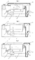
- the basic cooling circuit is shown as it is used to cool a Internal combustion engine 17 can be found in a vehicle.
- Components of the cycle are the coolant cooler 4, the expansion tank 2, the engine thermostat 9 and the coolant pump 8.
- the main cooling circuit 12 by means of the engine thermostat 9 on a short way, with the coolant cooler switched off 4, returned directly to the internal combustion engine 17.
- the internal combustion engine 17 heats the coolant in a short time.
- the Thermal energy of the coolant can be used, for example, to heat the passenger compartment are used, which should not be dealt with in the present case.
- a single oil / coolant heat exchanger 5 is in the circuit a gear oil cooler, whose flow 1 can be regulated by means of a valve unit 3 is.
- the valve unit 3 has a connection to the low-temperature coolant cooler 14 as part of the coolant cooler 4 and a further connection to the expansion tank 2.
- the engine thermostat 9 has already blocked the short way, so that the Main cooling circuit 12 through the coolant cooler 4 and back to the coolant pump 8 runs.
- the flow flow 1 of the heat exchanger 5 comes essentially from the low-temperature coolant cooler 14 of the water cooler 4.
- this Low-temperature coolant cooler 14 can, for example, reduce the coolant temperature 10 ° C can be cooled further, which is an advantage for the transmission oil cooling. 4 shows how this low-temperature coolant cooler 14 is part of the coolant cooler 4 is formed, which will be discussed in more detail below.
- FIG. 2 shows the pure preheating phase of the heat exchanger 5, in which the flow stream 1 is taken from the expansion tank 2, which is part of the main cooling circuit 12 is flowed through.
- the valve unit 3 has opened the inlet on the left and the right entrance leading to the low-temperature coolant cooler 14 is closed. Part of the coolant warmed up quickly by the internal combustion engine 17 becomes thus provided for rapid heating of the gear oil.
- FIG. 4 Another operating situation, not shown, arises when the temperature continues to rise on when the engine thermostat 9 is already partially open, the low-temperature coolant cooler 14 then only of a subset of the coolant cooler 4 flowing water is flowing through, as can be seen in principle from Fig. 1.
- the schematic coolant cooler 4 is shown in FIG. 4. With this coolant cooler 4, a low-temperature coolant cooler 14 is separated by 15 in the left water tank a partition 16 has been inserted, which causes the water or part of the water, to flow through the coolant cooler 4 in the opposite direction again cools down by an additional amount.
- the main cooling circuit 12 enters and leaves the coolant cooler 4 at the top left of the inlet connection 22 this after flowing through on the right-hand side at the outlet connection 23 in accordance with the drawing Arrow.
- the portion flowing through the low-temperature coolant cooler 14 forms the coolant bypass flow 13, which leaves this, bottom left, to in the designated 10 Enter flow channel that leads to the heat exchanger 5.
- the flow channel 10 is also shown in FIGS. 5 and 6, which is a surge tank 2 with the schematic valve unit 3 located in the bottom 21.
- the valve unit 3 is located in an insert housing 19, which consists of a lower 18 and an upper Receptacle 20 is made. These sockets are preferably made of plastic.
- the lower receptacle 18 forms a single component together with the flow channel 10, which comes from the low-temperature coolant cooler 14 and the flow channel 11, which leads from the receptacle 18 to the flow connection of the heat exchanger 5.
- the return channel 28 forms from the heat exchanger 5 with the return connection 29 of the expansion tank 2 and the return pipe 30, which is the connection to Return to the coolant pump 8 represents a single injection molded part made of plastic.
- FIG. 6 shows the essential details of the valve unit 3 already described receiving housing 19, the valve unit 3 itself, the better clarity half, not drawn, but was only indicated by reference number 3.
- the two parts of the housing 19, the lower receiving port 18 and the upper receiving port 20, which is part of the expansion tank 2, are outwards by means of a suitable seal 32 sealed.
- the connection is made through slots or groove 31 in the wall there is a spring clip that was not shown in the drawing.
- the arrows point the flow of water.
- the separate Conducting compact design in which the lower receptacle 18 and the flow channels 10 and 11 are formed as a single injection molded part. Because the top Receptacle 20, as already described, directly in the bottom 21 of the expansion tank 2 is molded on, the number of individual parts is extremely low, making it easy to install contributes.
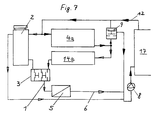
- FIG. 7 represents the represents pure cooling phase, in which the main cooling circuit 12 is passed through the coolant cooler 4a becomes.
- the arrows, drawn a little more strongly, show the predominant arrows in this phase Flow path of the cooling water.
- the low-temperature coolant cooler 14a is downstream of the coolant cooler 4a and is parallel to this. That in this cooler 14a inflowing water reaches the valve unit 3 and from there into the transmission oil cooler 5, where efficient oil cooling is possible due to the large temperature difference.
Landscapes
- Engineering & Computer Science (AREA)
- Chemical & Material Sciences (AREA)
- Combustion & Propulsion (AREA)
- Mechanical Engineering (AREA)
- General Engineering & Computer Science (AREA)
- Lubrication Of Internal Combustion Engines (AREA)
Description
- Fig. 1
- schematisches Schaltbild der Kühlphase eines Getriebeölkühlers;
- Fig. 2
- schematisches Schaltbild der Heiz-oder Vorwärmphase;
- Fig. 3
- schematisches Schaltbild in einer Übergangsphase;
- Fig. 4
- Kühlmittelkühler (schematisch) der in einem Wasserkasten eine Trennwand zur Bildung eines Niedertemperaturkühlmittelkühlers aufweist;
- Fig. 5
- Ausgleichsbehälter mit Aufnahmestutzen mit eingesetztem Thermostatventil und Kanälen zum angedeuteten Getriebeölkühler und zum Niedertemperaturkühlmittelkühler;
- Fig. 6
- Gehäuse bildende Aufnahmestutzen als Einzelheit;
- Fig. 7
- schematisiertes Schaltbild mit einem separaten Niedertemperaturkühlmittelkühler;
- 1
- Vorlaufstrom von 5
- 2
- Ausgleichsbehälter
- 3
- Ventileinheit
- 4
- Kühlmittelkühler
- 4a
- Kühlmittelkühler
- 5
- Wärmetauscher (Öl-Wasser-Kühler)
- 6
- Rücklaufstrom von 5
- 7
- Kühlmittelleitung
- 8
- Kühlmittelpumpe
- 9
- Motor-Haupthermostat
- 10
- Vorlaufkanal von 4 (14) nach 5
- 11
- Vorlaufkanal von 2 nach 5
- 12
- Hauptkühlkreislauf
- 13
- Kühlmittelnebenstrom
- 14
- Niedertemperaturkühlmittelkühler von 4
- 14a
- Niedertemperaturkühlmittelkühler bei 4a
- 15
- Wasserkasten von 4
- 16
- Trennwand in 15
- 17
- Brennkraftmaschine
- 18
- Aufnahmestutzen, unten
- 19
- Einsatzgehäuse für 3
- 20
- Aufnahmestutzen, oben am Ausgleichsbehälter 2
- 21
- Boden des Ausgleichsbehälters 2
- 22
- Einlaufstutzen an 4
- 23
- Auslaufstutzen an 4
- 24
- Anschlußstutzen an 14
- 25
- Flachrohre
- 26
- Lamellen
- 27
- Trennlinie für Niedertemperaturkühlmittelkühler 14
- 28
- Rücklaufkanal von 5
- 29
- Rücklaufanschluß an 2
- 30
- Rücklaufstutzen
- 31
- Nut für Federklammer
- 32
- Dichtung
Claims (11)
- Kühlkreislauf einer Brennkraftmaschine von Fahrzeugen, mit einem Hauptkühlkreislauf (12), bestehend aus einem Kühlmittelkühler (4;4a), einer Kühlmittelpumpe (8) und einem Motorthermostat (9), der den Kühlmittelkühler (4;4a) bei Erreichen einer vorbestimmten Temperatur des Kühlmittels in den die Kühlmittelpumpe (8) aufweisenden Kühlkreislauf einschaltet, sowie mit einem Niedertemperaturkühlmittelkühler (14;14a), einem Wärmetauscher (5) zum Vorwärmen und Kühlen von Betriebsstoffen, insbesonder Getriebeöl, mit Hilfe des Kühlmittels und einer Ventileinheit (3), die den Vorlaufstrom des Wärmetauschers (5) in der Vorwärmphase aus dem unter Umgehung des Kühlmittelskühlers (4,4a) zirkulierenden Kühlkreislauf der Brennkraftmaschine (17) und in der Kühlphase aus dem Niedertemperaturkühlmittelkühler (14;14a) abzweigt, wobei der Wärmetauscher (5) einen Vorlaufkanal (11) sowie einen Rücklaufkanal (28) in den Hauptkühlkreislauf (12) besitzt,
dadurch gekennzeichnet, daß
ein Ausgleichsbehälter (2) an dem Hauptkühlkreislauf (12) angeschlossen ist und die Ventileinheit (3) am Gehäuse des Ausgleichsbehälters angebracht ist, wobei die Ventileinheit (3) den Vorlaufstrom (1) des Wärmetauschers (5) in der Vorwärmphase aus dem Ausgleichsbehälter (2) zum Vorlaufkanal (11) abzweigt und in der Kühlphase aus dem Niedertemperaturkühlmittelkühler (14;14a) zum Vorlaufkanal (11) abzweigt, wobei die Ventileinheit (3) in einem Temperaturbereich des Kühlmittels zwischen der Vorwärmphase und der Kühlphase den Vorlaufstrom (1) des Wärmetauschers (5) aus Teilströmen aus dem Ausgleichsbehälter (2) und dem Niedertemperaturkühlmittelkühler (14;14a) mischt und daß der Rücklaufkanal (28) vom Wärmetauscher (5) mit einem Rücklaufanschluß (29) des Ausgleichsbehälters (2) in einen gemeinsamen Rücklaufstutzen (30) zum Hauptkühlkreislauf mündet. - Kühlkreislauf nach Anspruch 1, dadurch gekennzeichnet, daß die Reaktionstemperatur der Ventileinheit (3) unterhalb der Reaktionstemperatur des Motor-Hauptthermostaten (9) eingestellt ist.
- Kühlkreislauf nach den Ansprüchen 1 und 2, dadurch gekennzeichnet, daß sich die Ventileinheit (3) in einem Einsatzgehäuse (19) befindet, das in Verbindung zum Ausgleichsbehälter (2) steht und das zwei Vorlaufkanäle (10;11) zum Wärmetauscher (5) aufweist, von denen der eine Vorlaufkanal (10) in Verbindung mit dem Niedertemperaturkühlmittelkühler (14; 14a) und der andere Vorlaufkanal (11) in Verbindung mit dem Ausgleichsbehälter (2) ist.
- Kühlkreislauf nach Anspruch 3, dadurch gekennzeichnet, daß das Einsatzgehäuse (19) aus einem unteren (18) und einem oberen (20) Aufnahmestutzen gebildet ist, die abdichtend ineinandersteckbar sind, daß der obere Aufnahmestutzen (20) direkt am Boden (21) des Ausgleichsbehälters (2) angeformt ist und, daß der untere Aufnahmestutzen (18) gemeinsam mit den Vorlaufkanälen (10;11) ein einziges Bauteil, vorzugsweise ein Kunststoff-Spritzgußteil, darstellt.
- Kühlkreislauf nach Anspruch 4, dadurch gekennzeichnet, daß die die Ventileinheit (3) aufnehmenden unteren und oberen Aufnahmestutzen (18; 20) als ineinandersteckbare und abdichtende Schnell-Steck-Stutzen ausgebildet sind.
- Kühlkreislauf nach den Ansprüchen 4 und 5, dadurch gekennzeichnet, daß der Aufnahmestutzen (20) am Ausgleichsbehälter (2) innen eine einen O-Ring aufnehmende Nut aufweist und an seinem Umfang Schlitze (31) zur Aufnahme einer Federklammer besitzt und, daß der Aufnahmestutzen (18) eine konische Mantelfläche zeigt, die an dem O-Ring abdichtend anliegt sowie eine die Federklammer aufnehmende umlaufende Nut (31) besitzt.
- Kühlkreislauf nach einem der vorstehenden Ansprüche, dadurch gekennzeichnet, daß der Rücklaufkanal (28), der Rücklaufanschluß (29) und der Rücklaufstutzen (30) ein einziges Bauteil, vorzugsweise ein Kunststoff-Spritzgußteil, darstellen.
- Verfahren zum Betrieb des Kühlkreislaufes einer Brennkraftmaschine (17), mit dem das Vorwärmen und Kühlen von Betriebsstoffen, insbesondere Getriebeöl, mittels eines Wärmetauschers (5) durchgeführt wird, wobei ein Motorthermostat (9) den Kreislauf auf Kühlung mittels Kühlmittelkühler (4;4a) und Niedertemperaturkühlmittelkühler (14;14a) oder auf Vorwärmung schaltet, bei der die Kühler (4;4a;14;14a) nicht durchströmt werden und eine Ventileinheit (3) den Kühlmittelstrom durch den Wärmetauscher (5) regelt,
dadurch gekennzeichnet, daß der Vorlaufstrom (1) des Wärmetauschers (5) in der Vorwärmphase im wesentlichen aus dem Ausgleichsbehälter (2) entnommen wird, der von einem Teil des Hauptkühlkreislaufes (12) durchströmt wird, daß bei einer etwas unterhalb des Schaltpunktes des Motorthermostaten (9) liegenden Temperatur des Kühlmittels die Ventileinheit (3) auf Kühlphase umschaltet und in der Kühlphase der Vorlaufstrom (1) des Wärmetauschers (5) im wesentlichen aus dem Niedertemperaturkühlmittelkühler (14;14a) abgezweigt wird, daß der Vorlaufstrom (1) in einem Temperaturbereich zwischen Vorwärm-und Kühlphase gemischt wird und daß die Ventileinheit (3) einen Dauervorlaufstrom aus dem durch den Ausgleichsbehälter (2) geführten Kühlmittelstrom entnimmt und durch den Wärmetauscher (5) leitet. - Verfahren nach Anspruch 8, dadurch gekennzeichnet, daß dem minimalen Dauervorlaufstrom in der Kühlphase mit steigender Temperatur des Kühlmittels ein größer werdender Kühlmittelstrom aus dem Niedertemperaturkühlmittelkühler (14;14a) zugemischt wird.
- Verfahren nach den Ansprüchen 8, dadurch gekennzeichnet, daß nach Erreichen der Schalttemperatur bei weiter steigender Temperatur des Kühlmittels, der Anteil des den Vorlaufstrom (1) bildenden Kühlmittels aus dem Niedertemperaturkühlmittelkühler (14; 14a) erhöht und bei fallender Temperatur verringert wird.
- Verfahren nach einem der vorstehenden Ansprüche, dadurch gekennzeichnet, daß nach Erreichen der Schalttemperatur, bei weiter steigender Temperatur des Kühlmittels, der Anteil des den Vorlaufstrom (1) bildenden Kühlmittels aus dem Ausgleichsbehälter (2) bzw. aus dem den Kühlmittelkühler (4) nicht durchströmenden Kühlmittelstrom (12) verringert und bei fallender Temperatur erhöht wird.
Applications Claiming Priority (3)
| Application Number | Priority Date | Filing Date | Title |
|---|---|---|---|
| DE19637817A DE19637817A1 (de) | 1996-09-17 | 1996-09-17 | Einrichtung und Verfahren zum Kühlen und Vorwärmen |
| DE19637817 | 1996-09-17 | ||
| PCT/EP1997/004604 WO1998012425A1 (de) | 1996-09-17 | 1997-08-23 | Einrichtung und verfahren zum kühlen und vorwärmen |
Publications (2)
| Publication Number | Publication Date |
|---|---|
| EP0861368A1 EP0861368A1 (de) | 1998-09-02 |
| EP0861368B1 true EP0861368B1 (de) | 2000-04-12 |
Family
ID=7805856
Family Applications (1)
| Application Number | Title | Priority Date | Filing Date |
|---|---|---|---|
| EP97940120A Expired - Lifetime EP0861368B1 (de) | 1996-09-17 | 1997-08-23 | Kühlkreislauf einer brennkraftmaschine sowie verfahren zum betrieb des kühlkreislaufes |
Country Status (5)
| Country | Link |
|---|---|
| US (1) | US6196168B1 (de) |
| EP (1) | EP0861368B1 (de) |
| DE (2) | DE19637817A1 (de) |
| ES (1) | ES2146115T3 (de) |
| WO (1) | WO1998012425A1 (de) |
Cited By (6)
| Publication number | Priority date | Publication date | Assignee | Title |
|---|---|---|---|---|
| WO2004063543A2 (de) | 2003-01-16 | 2004-07-29 | Behr Gmbh & Co. Kg | Kühlkreislauf einer brennkraftmaschine mit niedertemperaturkühler |
| DE102006048527A1 (de) * | 2006-10-13 | 2008-04-17 | Volkswagen Ag | Kühlkreislauf für eine Brennkraftmaschine |
| DE102004004975B4 (de) * | 2004-01-31 | 2015-04-23 | Modine Manufacturing Co. | Plattenwärmeübertrager |
| DE102017219939A1 (de) | 2017-11-09 | 2019-05-09 | Volkswagen Aktiengesellschaft | Kühlkreislauf für eine Antriebseinheit eines Kraftfahrzeuges |
| DE102018202476A1 (de) | 2018-02-19 | 2019-08-22 | Volkswagen Aktiengesellschaft | Kühlkreislauf für eine Antriebseinheit eines Kraftfahrzeuges |
| US10844760B2 (en) | 2018-01-30 | 2020-11-24 | Cumming Power Generation IP, Inc. | Oil heater for a generator set |
Families Citing this family (75)
| Publication number | Priority date | Publication date | Assignee | Title |
|---|---|---|---|---|
| DE19715324A1 (de) | 1997-04-12 | 1998-10-15 | Bayerische Motoren Werke Ag | Wärmetauscher für flüssige Wärmetauschmittel |
| DE19942727A1 (de) * | 1999-09-08 | 2001-03-15 | Zahnradfabrik Friedrichshafen | Kühlkreislauf |
| DE10019029C5 (de) * | 2000-04-18 | 2017-11-23 | Mahle International Gmbh | Vorrichtung zum Kühlen und/oder Temperieren von Öl |
| US6427640B1 (en) * | 2000-10-11 | 2002-08-06 | Ford Global Tech., Inc. | System and method for heating vehicle fluids |
| FR2815402B1 (fr) * | 2000-10-13 | 2006-07-07 | Renault | Dispositif, systeme et procede de refroidissement d'un fluide caloporteur |
| FR2815299B1 (fr) * | 2000-10-13 | 2003-01-24 | Renault | Systeme et procede de refroidissement pour vehicule a propulsion hybride |
| FR2815401A1 (fr) * | 2000-10-13 | 2002-04-19 | Renault | Dispositif, systeme et procede de refroidissement d'un fluide caloporteur |
| DE10065002A1 (de) * | 2000-12-23 | 2002-07-11 | Bosch Gmbh Robert | Anordnung und Verfahren zum Kühlen |
| EP1362168B1 (de) * | 2001-01-05 | 2006-11-15 | Renault s.a.s. | Vorrichtung, system und verfahren zum kühlen eines kühlmittels |
| RU2202699C2 (ru) * | 2001-05-16 | 2003-04-20 | Общевойсковая Академия Вооруженных Сил Российской Федерации | Система охлаждения с автоматическим регулированием теплового состояния двигателя |
| DE10202613A1 (de) * | 2002-01-24 | 2003-07-31 | Zahnradfabrik Friedrichshafen | Vorrichtung zum Kühlen eines Getriebes |
| DE60325436D1 (de) * | 2002-03-27 | 2009-02-05 | Calsonic Kansei Corp | Kühlungseinrichtung einer wassergekühlten Brennkraftmascine und Getriebeölkühlermodul |
| DE10226928A1 (de) * | 2002-06-17 | 2004-01-08 | Siemens Ag | Verfahren zum Betrieb einer flüssigkeitsgekühlten Brennkraftmaschine |
| GB0220480D0 (en) * | 2002-09-04 | 2002-10-09 | Ford Global Tech Inc | A motor vehicle and a thermostatically controlled valve therefor |
| DE10241228B4 (de) * | 2002-09-06 | 2005-12-08 | Robert Bosch Gmbh | Kühlsystem für ein Kraftfahrzeug |
| DE10258504A1 (de) * | 2002-12-14 | 2004-07-08 | Zf Friedrichshafen Ag | Getriebe mit Getriebeölkanälen |
| DE10305914A1 (de) * | 2003-02-13 | 2004-08-26 | Zf Friedrichshafen Ag | Getriebe mit Getriebeölkanälen |
| US7082905B2 (en) * | 2003-02-24 | 2006-08-01 | Honda Motor Co., Ltd. | Cooling apparatus for hybrid vehicle |
| FR2852678B1 (fr) * | 2003-03-21 | 2005-07-15 | Valeo Thermique Moteur Sa | Systeme de refroidissement a basse temperature d'un equipement, notamment d'un equipement de vehicule automobile, et echangeurs de chaleur associes |
| GB0310120D0 (en) * | 2003-05-02 | 2003-06-04 | Ford Global Tech Llc | Engine cooling systems |
| GB0310122D0 (en) * | 2003-05-02 | 2003-06-04 | Ford Global Tech Llc | Temperature responsive flow control valves for engine cooling systems |
| DE10332949A1 (de) | 2003-07-19 | 2005-02-10 | Daimlerchrysler Ag | Vorrichtung zum Kühlen und Vorwärmen |
| EP1774148B1 (de) * | 2004-07-26 | 2013-02-27 | Behr GmbH & Co. KG | Kühlmittelkühler mit in einen der wasserkästen integriertem getriebeölkühler |
| FR2879044B1 (fr) | 2004-12-03 | 2007-03-02 | Renault Sas | Systeme de refroidissement pour chaine de traction hybride de vehicule automobile |
| FR2883806B1 (fr) * | 2005-03-31 | 2008-08-08 | Valeo Systemes Thermiques | Installation et procede de refroidissement d'un equipement de vehicule automobile |
| US8418487B2 (en) * | 2006-04-17 | 2013-04-16 | Martin P. King | Water chiller economizer system |
| SE530241C2 (sv) | 2006-10-03 | 2008-04-08 | Scania Cv Ab | Arrangemang för att kyla olja i en växellåda i ett fordon |
| DE102006054223A1 (de) * | 2006-11-15 | 2008-05-21 | Behr Gmbh & Co. Kg | Kühlsystem für ein Kraftfahrzeug |
| US8116953B2 (en) * | 2008-01-10 | 2012-02-14 | GM Global Technology Operations LLC | Active thermal management system and method for transmissions |
| US7669558B2 (en) * | 2007-07-16 | 2010-03-02 | Gm Global Technology Operations, Inc. | Integrated vehicle cooling system |
| SE531791C2 (sv) * | 2007-10-05 | 2009-08-04 | Scania Cv Ab | Arrangemang för att kyla olja i en växellåda i ett fordon |
| DE102007052926A1 (de) | 2007-11-07 | 2009-05-14 | Daimler Ag | Kühlmittelkreislauf für eine Brennkraftmaschine |
| DE102007052927A1 (de) * | 2007-11-07 | 2009-05-14 | Daimler Ag | Kühlmittelkreislauf für eine Brennkraftmaschine |
| SE532929C2 (sv) * | 2007-12-13 | 2010-05-11 | Scania Cv Abp | Kylsystem hos motorfordon |
| JP2011508851A (ja) * | 2008-01-03 | 2011-03-17 | マック トラックス インコーポレイテッド | 排気ガス再循環冷却回路 |
| FR2927416A1 (fr) * | 2008-02-11 | 2009-08-14 | Renault Sas | Echangeur thermique pour un vehicule automobile et vehicule associe |
| JP5191792B2 (ja) * | 2008-05-07 | 2013-05-08 | ヤンマー株式会社 | 定置式エンジンの冷却水回路 |
| DE102009000777A1 (de) | 2009-02-11 | 2010-08-12 | Zf Friedrichshafen Ag | Verfahren und Einrichtung zur Verbesserung des Wirkungsgrades von Getrieben in Landwirtschaftsfahrzeugen |
| US9187083B2 (en) | 2009-09-16 | 2015-11-17 | Polaris Industries Inc. | System and method for charging an on-board battery of an electric vehicle |
| EP2308708B1 (de) * | 2009-09-16 | 2016-08-17 | swissauto powersport llc | Elektrofahrzeug mit Reichweitenverlängerung |
| DE102010003146A1 (de) * | 2010-03-23 | 2011-09-29 | Ford Global Technologies, Llc | Verfahren zum Abkühlen einer Fahrzeugkabine |
| US8631772B2 (en) * | 2010-05-21 | 2014-01-21 | Ford Global Technologies, Llc | Transmission fluid warming and cooling method |
| US8205709B2 (en) | 2010-05-21 | 2012-06-26 | Ford Global Technologies, Llc. | Transmission fluid warming and cooling system |
| KR20120036134A (ko) * | 2010-10-07 | 2012-04-17 | 현대자동차주식회사 | 하이브리드 차량의 냉각시스템 |
| US8463495B2 (en) * | 2010-12-01 | 2013-06-11 | GM Global Technology Operations LLC | Method for controlling exhaust gas heat recovery systems in vehicles |
| US8485932B2 (en) * | 2011-01-06 | 2013-07-16 | Chrysler Group Llc | Axle system |
| FR2982935B1 (fr) * | 2011-11-22 | 2014-01-10 | Peugeot Citroen Automobiles Sa | Dispositif de gestion thermique d'une chaine de traction d'un vehicule hybride ou electrique |
| US8991339B2 (en) * | 2012-03-30 | 2015-03-31 | Ford Global Technologies, Llc | Multi-zone vehicle radiators |
| DE102012210054A1 (de) * | 2012-06-14 | 2013-12-19 | Bayerische Motoren Werke Aktiengesellschaft | Kühlmittelkreislauf für eine Brennkraftmaschine und Verfahren zum Betrieb der Brennkraftmaschine |
| KR101339257B1 (ko) * | 2012-09-24 | 2013-12-09 | 현대자동차 주식회사 | 차량의 엔진 냉각 시스템 및 방법 |
| KR101410650B1 (ko) * | 2012-12-07 | 2014-06-24 | 현대자동차주식회사 | Atf의 리저버 |
| JP2014227921A (ja) * | 2013-05-23 | 2014-12-08 | ヤマハ発動機株式会社 | 内燃機関の冷却装置およびそれを備えた自動二輪車 |
| DE102013209965A1 (de) * | 2013-05-28 | 2014-12-04 | Behr Thermot-Tronik Gmbh | Thermostatventil |
| US10378421B2 (en) | 2014-09-19 | 2019-08-13 | Ford Global Technologies, Llc | Automatic transmission fluid thermal conditioning system |
| US10300786B2 (en) | 2014-12-19 | 2019-05-28 | Polaris Industries Inc. | Utility vehicle |
| US10087793B2 (en) | 2015-01-26 | 2018-10-02 | Modine Manufacturing Company | Thermal management unit for vehicle powertrain |
| US10619530B2 (en) | 2015-01-26 | 2020-04-14 | Modine Manufacturing Company | Thermal management unit for vehicle powertrain |
| MX2017014403A (es) | 2015-05-15 | 2018-04-11 | Polaris Inc | Vehiculo utilitario. |
| US10118477B2 (en) | 2016-06-14 | 2018-11-06 | Polaris Industries Inc. | Hybrid utility vehicle |
| US10520075B2 (en) * | 2017-05-31 | 2019-12-31 | Mahle International Gmbh | Apparatus for controlling the temperature of an oil cooler in a motor vehicle |
| FR3080443B1 (fr) * | 2018-04-18 | 2020-06-19 | Renault S.A.S. | Radiateur de refroidissement avec by-pass integre et circuit de refroidissement |
| DE102018117136A1 (de) * | 2018-07-16 | 2020-01-16 | Claas Tractor Sas | Kühlsystem für eine landwirtschaftliche Maschine |
| DE102018213067B4 (de) * | 2018-08-03 | 2022-06-23 | Audi Ag | Verfahren zum Betreiben eines Antriebsstrangs eines Kraftfahrzeugs, insbesondere eines Kraftwagens |
| US10780770B2 (en) | 2018-10-05 | 2020-09-22 | Polaris Industries Inc. | Hybrid utility vehicle |
| CN109488438B (zh) * | 2018-11-19 | 2020-10-09 | 安徽江淮汽车集团股份有限公司 | 一种带dct冷却大循环回路的冷却系统 |
| CN109882282B (zh) * | 2019-01-28 | 2024-11-12 | 玉山创发数字科技有限公司 | 中冷绝热内燃机的中间冷却散热系统 |
| CA3299413A1 (en) | 2019-04-30 | 2026-03-02 | Polaris Industries Inc. | Vehicle with removable final drive |
| US11370266B2 (en) | 2019-05-16 | 2022-06-28 | Polaris Industries Inc. | Hybrid utility vehicle |
| US12187127B2 (en) | 2020-05-15 | 2025-01-07 | Polaris Industries Inc. | Off-road vehicle |
| US11691674B2 (en) | 2020-05-15 | 2023-07-04 | Polaris Industries Inc. | Off-road vehicle |
| RU2755418C1 (ru) * | 2020-12-28 | 2021-09-15 | Виктор Эдуардович Шефер | Автоматизированная система регулирования температурного режима силовой установки танка |
| US12485981B2 (en) | 2021-03-24 | 2025-12-02 | Polaris Industries Inc. | Electric recreational vehicle |
| CA3156559A1 (en) | 2021-05-05 | 2022-11-05 | Polaris Industries Inc. | Exhaust assembly for a utility vehicle |
| MX2023006716A (es) | 2022-06-13 | 2023-12-14 | Polaris Inc | Tren de potencia para vehiculo utilitario. |
| US12312993B2 (en) | 2023-05-30 | 2025-05-27 | Volvo Car Corporation | Two zone radiator cooling system |
Family Cites Families (22)
| Publication number | Priority date | Publication date | Assignee | Title |
|---|---|---|---|---|
| US2188172A (en) * | 1937-01-06 | 1940-01-23 | Gen Electric | Heat transfer system |
| DE766237C (de) * | 1938-02-17 | 1952-04-21 | Sueddeutsche Kuehler Behr | Fluessigkeitsgekuehlter OElkuehler fuer Brennkraftmaschinen mit Heisskuehlung |
| US2435041A (en) * | 1945-02-10 | 1948-01-27 | Frederic W Hild | Regulating device for cooling systems |
| US2670933A (en) * | 1950-02-24 | 1954-03-02 | Thomas J Bay | Engine cooling apparatus |
| US3134371A (en) * | 1962-10-29 | 1964-05-26 | Cooper Bessemer Corp | Cooling system for internal combustion engines |
| BE795230A (fr) * | 1972-02-10 | 1973-05-29 | Bayerische Motoren Werke Ag | Dispositif de refroidissement par ciculation pour des moteurs a combustion interne a pistons |
| FR2341041A1 (fr) * | 1976-02-10 | 1977-09-09 | Chausson Usines Sa | Dispositif pour la regulation de la temperature d'un moteur diesel suralimente |
| DE3047672A1 (de) * | 1980-12-18 | 1982-07-22 | Aktiengesellschaft Adolph Saurer, 9320 Arbon | Kuehleinrichtung zur kuehlung einer brennkraftmaschine und der ladeluft |
| DD158415A1 (de) * | 1981-04-16 | 1983-01-12 | Hans Berg | Kuehlsystem einer brennkraftmaschine mit abgasturboaufladung und ladeluftkuehlung |
| US4517929A (en) * | 1983-09-23 | 1985-05-21 | International Harvester Company | Self-adjusting cooling system for diesel engines |
| DE3517567A1 (de) * | 1984-05-29 | 1985-12-05 | Volkswagenwerk Ag, 3180 Wolfsburg | Antriebsanlage fuer geraete und fahrzeuge, insbesondere kraftfahrzeuge |
| DE3527020A1 (de) * | 1985-07-27 | 1987-01-29 | Porsche Ag | Fluessigkeitsgekuehlte antriebseinheit fuer ein fahrzeug |
| DE3622378A1 (de) * | 1986-07-03 | 1988-01-14 | Kloeckner Humboldt Deutz Ag | Kuehlfluessigkeitssystem fuer eine brennkraftmaschine |
| DE3708351A1 (de) * | 1987-03-14 | 1988-06-01 | Mtu Friedrichshafen Gmbh | Umlaufkuehlsystem |
| JPS6419157A (en) * | 1987-07-10 | 1989-01-23 | Kubota Ltd | Waste heat recovering device for water cooled engine |
| US4883225A (en) * | 1988-03-18 | 1989-11-28 | S.T.C., Inc. | Fail-safe thermostat for vehicular cooling systems |
| DE4104093A1 (de) | 1991-02-11 | 1992-08-13 | Behr Gmbh & Co | Kuehlanlage fuer ein fahrzeug mit verbrennungsmotor |
| FR2682160B1 (fr) * | 1991-10-07 | 1995-04-21 | Renault Vehicules Ind | Systeme de refroidissement pour moteur a combustion interne comportant deux parties distinctes de radiateur. |
| DE4308002C1 (de) * | 1993-03-13 | 1994-08-25 | Iav Gmbh | Verteilereinrichtung für das Kühl- bzw. Heizsystem von Fahrzeugen mit Verbrennungsmotoren |
| DE4324749A1 (de) * | 1993-07-23 | 1995-01-26 | Freudenberg Carl Fa | Regelventil |
| BR9501795A (pt) * | 1994-04-27 | 1995-12-12 | Schatz Thermo System Gmbh | Método e conjunto para operação de amazenadores de calor sensível |
| JP3602599B2 (ja) * | 1995-03-02 | 2004-12-15 | 本田技研工業株式会社 | 車両用油圧作動式変速機の制御装置 |
-
1996
- 1996-09-17 DE DE19637817A patent/DE19637817A1/de not_active Withdrawn
-
1997
- 1997-08-23 DE DE59701435T patent/DE59701435D1/de not_active Expired - Lifetime
- 1997-08-23 ES ES97940120T patent/ES2146115T3/es not_active Expired - Lifetime
- 1997-08-23 WO PCT/EP1997/004604 patent/WO1998012425A1/de not_active Ceased
- 1997-08-23 US US09/068,815 patent/US6196168B1/en not_active Expired - Lifetime
- 1997-08-23 EP EP97940120A patent/EP0861368B1/de not_active Expired - Lifetime
Cited By (9)
| Publication number | Priority date | Publication date | Assignee | Title |
|---|---|---|---|---|
| WO2004063543A2 (de) | 2003-01-16 | 2004-07-29 | Behr Gmbh & Co. Kg | Kühlkreislauf einer brennkraftmaschine mit niedertemperaturkühler |
| US7406929B2 (en) | 2003-01-16 | 2008-08-05 | Behr Gmbh & Co. Kg | Cooling circuit of an internal combustion engine comprising a low-temperature radiator |
| EP2573354A1 (de) | 2003-01-16 | 2013-03-27 | Behr GmbH & Co. KG | Kühlkreislauf einer Brennkraftmaschine mit Niedertemperaturkühler |
| DE102004004975B4 (de) * | 2004-01-31 | 2015-04-23 | Modine Manufacturing Co. | Plattenwärmeübertrager |
| DE102006048527A1 (de) * | 2006-10-13 | 2008-04-17 | Volkswagen Ag | Kühlkreislauf für eine Brennkraftmaschine |
| DE102006048527B4 (de) * | 2006-10-13 | 2016-12-22 | Volkswagen Ag | Kühlkreislauf für eine Brennkraftmaschine |
| DE102017219939A1 (de) | 2017-11-09 | 2019-05-09 | Volkswagen Aktiengesellschaft | Kühlkreislauf für eine Antriebseinheit eines Kraftfahrzeuges |
| US10844760B2 (en) | 2018-01-30 | 2020-11-24 | Cumming Power Generation IP, Inc. | Oil heater for a generator set |
| DE102018202476A1 (de) | 2018-02-19 | 2019-08-22 | Volkswagen Aktiengesellschaft | Kühlkreislauf für eine Antriebseinheit eines Kraftfahrzeuges |
Also Published As
| Publication number | Publication date |
|---|---|
| DE19637817A1 (de) | 1998-03-19 |
| ES2146115T3 (es) | 2000-07-16 |
| WO1998012425A1 (de) | 1998-03-26 |
| EP0861368A1 (de) | 1998-09-02 |
| DE59701435D1 (de) | 2000-05-18 |
| US6196168B1 (en) | 2001-03-06 |
Similar Documents
| Publication | Publication Date | Title |
|---|---|---|
| EP0861368B1 (de) | Kühlkreislauf einer brennkraftmaschine sowie verfahren zum betrieb des kühlkreislaufes | |
| DE69004220T2 (de) | Wärmetauscher mit einer umfangsförmigen Zirkulation. | |
| DE102012105644B4 (de) | Wärmetauscher für ein fahrzeug | |
| EP1588034B1 (de) | Kühlkreislauf einer brennkraftmaschine mit niedertemperaturkühler | |
| DE102012105047B4 (de) | Wärmetauschereinheit des Kerntyps mit variabler Kapazität | |
| EP3747074B1 (de) | Kühlsystem für brennstoffzellenstacks | |
| DE4433814B4 (de) | Kraftfahrzeug | |
| DE19849492B4 (de) | Steuervorrichtung für einen Kühlkreislauf einer Brennkraftmaschine | |
| EP0751877B1 (de) | Zusatzheizungs-anordnung | |
| EP1319815A2 (de) | Kühlkreislauf einer flüssigkeitsgekühlten Brennkraftmaschine | |
| DE19961825A1 (de) | Kühl-Heiz-Kreis mit zwei Kühlern | |
| EP0855304B1 (de) | Kühlmodul | |
| EP0903482A2 (de) | Vorrichtung zur Regelung des Kühlwasserkreislaufes für einen Verbrennungsmotor | |
| DE60123881T2 (de) | Vorrichtung zur thermischen Regelung der Ansaugluft einer Brennkraftmaschine eines Kraftfahrzeuges | |
| DE60216049T2 (de) | Vorrichtung, system und verfahren zum kühlen eines kühlmittels | |
| DE19506935C1 (de) | Kühlmittelkreislauf für einen Verbrennungsmotor eines Kraftfahrzeugs | |
| DE10160380A1 (de) | Vorrichtung zur Wärmeübertragung | |
| EP1008471B1 (de) | Kühl- und Heizungskreislauf sowie Wärmetauscher für Kraftfahrzeuge mit zusätzlicher Kühlmittel-Heizeinrichtung | |
| WO2008046490A1 (de) | Kühlkreislauf für eine brennkraftmaschine | |
| DE3517567A1 (de) | Antriebsanlage fuer geraete und fahrzeuge, insbesondere kraftfahrzeuge | |
| DE19712479B4 (de) | Kühleinrichtung für den Kraftstoff der Einspritzanlage von Verbrennungsmotoren | |
| DE4033796A1 (de) | Einkreiskuehlsystem fuer brennkraftmaschinen | |
| EP2194245A2 (de) | Öl-Abgas-Kühlmodul für eine Verbrennungskraftmaschine | |
| DE4345532B4 (de) | Kühlsystem eines elektrischen Kraftfahrzeugs und eines dafür benutzten Elektromotors | |
| DE4139886C2 (de) | Wärmeträgerkreislauf eines Fahrzeuges |
Legal Events
| Date | Code | Title | Description |
|---|---|---|---|
| PUAI | Public reference made under article 153(3) epc to a published international application that has entered the european phase |
Free format text: ORIGINAL CODE: 0009012 |
|
| 17P | Request for examination filed |
Effective date: 19980428 |
|
| AK | Designated contracting states |
Kind code of ref document: A1 Designated state(s): DE ES FR GB IT SE |
|
| 17Q | First examination report despatched |
Effective date: 19981110 |
|
| RAP1 | Party data changed (applicant data changed or rights of an application transferred) |
Owner name: MODINE MANUFACTURING COMPANY Owner name: BAYERISCHE MOTOREN WERKE AKTIENGESELLSCHAFT |
|
| GRAG | Despatch of communication of intention to grant |
Free format text: ORIGINAL CODE: EPIDOS AGRA |
|
| GRAG | Despatch of communication of intention to grant |
Free format text: ORIGINAL CODE: EPIDOS AGRA |
|
| GRAG | Despatch of communication of intention to grant |
Free format text: ORIGINAL CODE: EPIDOS AGRA |
|
| GRAH | Despatch of communication of intention to grant a patent |
Free format text: ORIGINAL CODE: EPIDOS IGRA |
|
| GRAH | Despatch of communication of intention to grant a patent |
Free format text: ORIGINAL CODE: EPIDOS IGRA |
|
| RTI1 | Title (correction) |
Free format text: INTERNAL COMBUSTION ENGINE COOLING SYSTEM AND METHOD FOR OPERATING SAID SYSTEM |
|
| GRAA | (expected) grant |
Free format text: ORIGINAL CODE: 0009210 |
|
| AK | Designated contracting states |
Kind code of ref document: B1 Designated state(s): DE ES FR GB IT SE |
|
| ITF | It: translation for a ep patent filed | ||
| REF | Corresponds to: |
Ref document number: 59701435 Country of ref document: DE Date of ref document: 20000518 |
|
| ET | Fr: translation filed | ||
| GBT | Gb: translation of ep patent filed (gb section 77(6)(a)/1977) |
Effective date: 20000519 |
|
| REG | Reference to a national code |
Ref country code: ES Ref legal event code: FG2A Ref document number: 2146115 Country of ref document: ES Kind code of ref document: T3 |
|
| PLBE | No opposition filed within time limit |
Free format text: ORIGINAL CODE: 0009261 |
|
| STAA | Information on the status of an ep patent application or granted ep patent |
Free format text: STATUS: NO OPPOSITION FILED WITHIN TIME LIMIT |
|
| 26N | No opposition filed | ||
| REG | Reference to a national code |
Ref country code: GB Ref legal event code: IF02 |
|
| REG | Reference to a national code |
Ref country code: FR Ref legal event code: PLFP Year of fee payment: 19 |
|
| REG | Reference to a national code |
Ref country code: FR Ref legal event code: PLFP Year of fee payment: 20 |
|
| PGFP | Annual fee paid to national office [announced via postgrant information from national office to epo] |
Ref country code: DE Payment date: 20160831 Year of fee payment: 20 Ref country code: IT Payment date: 20160831 Year of fee payment: 20 Ref country code: GB Payment date: 20160830 Year of fee payment: 20 |
|
| PGFP | Annual fee paid to national office [announced via postgrant information from national office to epo] |
Ref country code: SE Payment date: 20160825 Year of fee payment: 20 Ref country code: FR Payment date: 20160825 Year of fee payment: 20 |
|
| PGFP | Annual fee paid to national office [announced via postgrant information from national office to epo] |
Ref country code: ES Payment date: 20160819 Year of fee payment: 20 |
|
| REG | Reference to a national code |
Ref country code: DE Ref legal event code: R071 Ref document number: 59701435 Country of ref document: DE |
|
| REG | Reference to a national code |
Ref country code: GB Ref legal event code: PE20 Expiry date: 20170822 |
|
| REG | Reference to a national code |
Ref country code: SE Ref legal event code: EUG |
|
| PG25 | Lapsed in a contracting state [announced via postgrant information from national office to epo] |
Ref country code: GB Free format text: LAPSE BECAUSE OF EXPIRATION OF PROTECTION Effective date: 20170822 |
|
| REG | Reference to a national code |
Ref country code: ES Ref legal event code: FD2A Effective date: 20180508 |
|
| PG25 | Lapsed in a contracting state [announced via postgrant information from national office to epo] |
Ref country code: ES Free format text: LAPSE BECAUSE OF EXPIRATION OF PROTECTION Effective date: 20170824 |