EP0857500A2 - Vorrichtung zum Montieren einer Skibindung - Google Patents
Vorrichtung zum Montieren einer Skibindung Download PDFInfo
- Publication number
- EP0857500A2 EP0857500A2 EP98101794A EP98101794A EP0857500A2 EP 0857500 A2 EP0857500 A2 EP 0857500A2 EP 98101794 A EP98101794 A EP 98101794A EP 98101794 A EP98101794 A EP 98101794A EP 0857500 A2 EP0857500 A2 EP 0857500A2
- Authority
- EP
- European Patent Office
- Prior art keywords
- ski
- lifting plate
- feature
- fixed part
- lifting
- Prior art date
- Legal status (The legal status is an assumption and is not a legal conclusion. Google has not performed a legal analysis and makes no representation as to the accuracy of the status listed.)
- Withdrawn
Links
- 230000027455 binding Effects 0.000 title claims abstract description 21
- 238000009739 binding Methods 0.000 title claims abstract description 21
- 229920001971 elastomer Polymers 0.000 claims abstract description 4
- -1 polytetrafluoroethylene Polymers 0.000 claims abstract description 4
- 229920001343 polytetrafluoroethylene Polymers 0.000 claims abstract description 4
- 239000004810 polytetrafluoroethylene Substances 0.000 claims abstract description 4
- 239000005060 rubber Substances 0.000 claims abstract description 4
- 229920002430 Fibre-reinforced plastic Polymers 0.000 claims abstract description 3
- 239000011151 fibre-reinforced plastic Substances 0.000 claims abstract description 3
- 238000004904 shortening Methods 0.000 claims abstract description 3
- 238000013016 damping Methods 0.000 claims description 3
- 239000013013 elastic material Substances 0.000 claims description 3
- 229910001069 Ti alloy Inorganic materials 0.000 claims description 2
- 229910052751 metal Inorganic materials 0.000 claims description 2
- 239000002184 metal Substances 0.000 claims description 2
- 229910001092 metal group alloy Inorganic materials 0.000 claims description 2
- 230000001681 protective effect Effects 0.000 claims description 2
- 238000010276 construction Methods 0.000 abstract description 7
- 238000005452 bending Methods 0.000 abstract description 4
- 230000005540 biological transmission Effects 0.000 abstract description 2
- 239000000463 material Substances 0.000 abstract description 2
- RTAQQCXQSZGOHL-UHFFFAOYSA-N Titanium Chemical compound [Ti] RTAQQCXQSZGOHL-UHFFFAOYSA-N 0.000 abstract 1
- 229910001234 light alloy Inorganic materials 0.000 abstract 1
- 229910052719 titanium Inorganic materials 0.000 abstract 1
- 239000010936 titanium Substances 0.000 abstract 1
- 238000011161 development Methods 0.000 description 3
- 230000018109 developmental process Effects 0.000 description 3
- 230000008901 benefit Effects 0.000 description 2
- 238000007688 edging Methods 0.000 description 2
- 238000011089 mechanical engineering Methods 0.000 description 2
- 241000270272 Coluber Species 0.000 description 1
- 238000004519 manufacturing process Methods 0.000 description 1
- 230000007935 neutral effect Effects 0.000 description 1
Images

Classifications
-
- A—HUMAN NECESSITIES
- A63—SPORTS; GAMES; AMUSEMENTS
- A63C—SKATES; SKIS; ROLLER SKATES; DESIGN OR LAYOUT OF COURTS, RINKS OR THE LIKE
- A63C9/00—Ski bindings
- A63C9/003—Non-swivel sole plate fixed on the ski
-
- A—HUMAN NECESSITIES
- A63—SPORTS; GAMES; AMUSEMENTS
- A63C—SKATES; SKIS; ROLLER SKATES; DESIGN OR LAYOUT OF COURTS, RINKS OR THE LIKE
- A63C9/00—Ski bindings
- A63C9/007—Systems preventing accumulation of forces on the binding when the ski is bending
Definitions
- the invention relates to devices for mounting a Ski binding on a ski according to the preamble of the claim 1.
- Skis for both downhill and cross-country skiing are manufactured so that they are in the middle area, where the Ski binding is mounted, are convex. This Longitudinal curvature disappears under the influence of the weight of the Skier. At the same time, the ski tip and ski tips become corresponding forces in the snow. Thereby the ski gets good contact with the snow, keeps the track well, does not flutter when driving etc. However, this hinders Longitudinal curvature turning the ski; the skier must if necessary, by means of active high or low relief Improve turning of the skis.
- WO-A 95/32035 is a lever construction known, with the help of the longitudinal curvature of the ski during driving can be actively changed.
- the present invention has for its object a Specify the device by means of which the distance between Skis and bindings or shoes changed while driving can be and yet a uniform bending line of the Skis is guaranteed.
- the more the ski bends, the bigger the lift plate moves further away from the ski. Otherwise leaves the stroke can also be influenced by the length of the Lifting plate and the gear ratio of the transmission, which is the curvature of the ski or the one entering it Shortening the top of the ski converts to the stroke.
- the Construction according to the invention can be retrofitted to any ski. Ski racers can also use the present invention benefit a lot, because for the first time it is possible to Distance between ski and binding or boot dynamically to the adapt each driving situation.
- Another advantage would be that the ski boots holding ski binding no longer built-in length compensation needed, which simplifies the binding construction and cheaper and especially the triggering behavior in the event of a fall significantly improved.
- a preferred one Realization is a tongue and groove connection between Lift plate and ski, especially between lift plate and Fixed part, tongue and groove preferably in the longitudinal direction of the ski.
- the lifting plate on Fixed part can be moved, but cannot be lost, is according to a development of the invention in the groove limiting leg a cross hole in the spring Elongated hole introduced.
- the elongated hole extends parallel to the sliding surfaces.
- One through cross hole and slot inserted holding pin completes the connection.
- a fixed part and lifting plate provided a dovetail connection will. This transmits the forces when edging the ski and fixes the lifting plate captively on the fixed part.
- all sliding surfaces with one layer be occupied with a low coefficient of friction, e.g. B. with a Polytetrafluoroethylene layer.
- the intermediate layer has the task To prevent damage to the ski surface.
- the main task is to lift the lifting plate resulting gap between the lifting plate and the ski seal to prevent the ingress of ice and snow prevent.
- this can be elastic Intermediate layer can also be used as a spring to the Lift plate by part of the weight of the skier too relieve.
- the elastic intermediate layer can consist of different Materials exist, for example under the fixed part harder and / or thinner and softer under the lifting plate and / or be made thicker. It can also Intermediate layer itself consisting of several layers be composed.
- the elastic intermediate layer can also be used.
- Damping layer e.g. B. made of rubber, in the slot integrate where it slows down the movement of the retaining pin.
- Alternatively can also be a fixed part and / or lifting plate made of metal exist, for example a light metal alloy or a titanium alloy.
- the lifting plate can also less if necessary be rigid. In this way, too Dependency between ski curvature and lifting height influence. As a rule, however, the lifting plate rigidly executed.
- the fixed parts can be retrofitted every standard ski can be mounted. Alternatively, there is the possibility of the fixed parts at the same time Integrate production into the ski or into the binding.
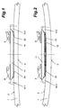
- Fig. 1 shows a side view of a section of a ski 1 at rest, the bottom 3 in the area of Binding is arched.
- the device On the top 2 of the ski 1 is a device mounted, with the help of which it is possible to adjust the distance between ski 1 and binding 8, 9 or boot (not shown) to change while driving.
- the device consists of a front and a rear fixed part 10.1, 10.2.
- a lifting plate 11 sits between the two 10.1, 10.2 and the lifting plate 11 have each other corresponding wedge-shaped sliding surfaces 23, so are oriented that the lifting plate 11 can be raised.
- Fig. 2 shows the state that occurs when cornering with edge grip. Since the Ski 1 is about its neutral zone bends, the top of the ski shortens 2. The Distance between the two fixed parts 10.1, 10.2 shortened also and the lifting plate 11 slips the sliding surfaces 23 high. As desired for cornering you get this way a large distance between ski 1 and ski binding or Shoe.
- the elastic intermediate layer 19 fills the gap Lift plate 11 and ski surface 2 and prevents that Ingress of ice and snow.
- FIG 3 and 5 show a side view and a top view Fixed part 10.3, FIGS. 4 and 6 as a side view and Top view of the end section of a matching lifting plate 11.
- the fixed part 10 is initially with three holes 20 equipped for mounting on the ski 1. It has one centric spring 21 and one each on the right and left wedge-shaped sliding surface 23.
- the end of the spring 21 is also designed as a sliding surface 25. Besides, that is End 22 of the spring 21 widened like a dovetail.
- the matching end of the lifting plate 11 has a groove 31 and with sliding surfaces 33, 35 and the dovetail 22 matching undercut 32 equipped.
- the corresponding sliding surfaces 23, 33; 25, 35 do that Raising the lifting plate 11, groove 31 and spring 21 cause the Transfer of forces when edging the ski 1 and the Dovetail connection 22, 32 holds the lifting plate 11 captive on the fixed part 10.
- FIG. 7 to 10 show an alternative embodiment of Fixed part 10.4 and lifting plate 11.
- Fixed part 10.4 with the groove 51
- the lifting plate 11 with the spring 41 equipped.
- An elongated hole 44 is in the spring 41 incorporated, which is parallel to the sliding surfaces 43, 45 extends.
- Through the legs 56 next to the groove 51 introduced a transverse bore 54.
- a retaining pin (not shown) inserted fixed part 10.4 and lifting plate 11 are captive connected.
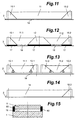
- FIG. 11 again shows that already in FIGS. 1 and 2 shown three-part lifting device, consisting of two Fixed parts 10.1, 10.2 and a lifting plate 11. Between the Ski surface 2 and the fixed parts 10.1, 10.2 and the Lift plate 11 is a continuous elastic Intermediate layer 18.
- Fig. 12 shows one of three fixed parts 10.1, 10.2, 12 and two lifting plates 11.1, 11.2 existing variant. Between the Ski surface 2 and the fixed parts 10.1, 10.2, 12 is located an elastic intermediate layer 17, preferably greater hardness. Between the ski surface 2 and the There is also a lifting plate 11.1, 11.2 elastic intermediate layer 19 of other hardness.
- Fig. 13 shows a six-part lifting device, consisting from four fixed parts 10.1, 10.2, 13.1, 13.2 and two Lifting plates 11.1, 11.2.
- the two middle fixed parts 13.1, 13.2 are spaced apart.
- Between ski surface 2 and the fixed parts or the lifting plates is one elastic intermediate layer 16 of greater thickness.
- intermediate layer 16 is in one piece and connects the two separate lifting devices.
- the two Lifting devices with different wedge angles a, b be equipped.
- the one on the left in the drawing Lifting device has steep wedge angles a, which in the Drawing right lifting device, however, flatter wedge angles b.
- the lengths of the two lifting plates 11.1, 11.2 different. In this way, the lifting plates 11.1, 11.2 different heights with the same ski curvature raised.
- Fig. 14 finally shows a two-part only Lifting device, consisting of a fixed part 10.2 and one Lifting plate 14.
- the lifting plate 14 is on its from the fixed part 10.2 spaced end directly connected to the ski 1.
- Fixed part 10.2 and lifting plate 14 are omitted because these forces of the lifting plate 14 can be transferred directly into the ski 1.
- the lifting plate 14 is not so rigid can be as in the previously described cases, but must have a certain elasticity to the stroke enable.
- ski 15 shows a cross section through ski 1, lifting plate 11 and intermediate layer 19.
- the lifting plate 11 must also be covered on the ski 1 11 protective strips 60 to the right and left of the lifting plate assembled. These are made from an elastic material not to disturb the even bending line of the ski.
Landscapes
- Footwear And Its Accessory, Manufacturing Method And Apparatuses (AREA)
- Fittings On The Vehicle Exterior For Carrying Loads, And Devices For Holding Or Mounting Articles (AREA)
Abstract
Description
- Fig. 1
- einen zentralen Ausschnitt eines Skis in Ruhestellung als Seitenansicht,
- Fig. 2
- den Ausschnitt der Fig. 1, jedoch bei gekrümmtem Ski,
- Fig. 3
- ein erstes Fixteil in Seitenansicht,
- Fig. 4
- einen dazu passenden Endabschnitt einer ersten Hubplatte in Seitenansicht,
- Fig. 5
- eine Draufsicht auf das Fixteil der Fig. 3,
- Fig. 6
- eine Draufsicht auf die Hubplatte der Fig. 4,
- Fig. 7
- ein zweites Fixteil in Seitenansicht,
- Fig. 8
- einen dazu passenden Endabschnitt einer zweiten Hubplatte in Seitenansicht,
- Fig. 9
- eine Draufsicht auf das Fixteil der Fig. 7,
- Fig. 10
- eine Draufsicht auf die Hubplatte der Fig. 8,
- Fig. 11
- eine dreiteilige Hubvorrichtung in Seitenansicht,
- Fig. 12
- eine fünfteilige Hubvorrichtung in Seitenansicht,
- Fig. 13
- eine sechsteilige Hubvorrichtung in Seitenansicht,
- Fig. 14
- eine zweiteilige Hubvorrichtung in Seitenansicht und
- Fig. 15
- einen Querschnitt durch einen Ski mit einer alternativen Hubvorrichtung.
Claims (16)
- Vorrichtung zum Montieren einer Skibindung (8, 9) auf einem Ski (1), gekennzeichnet durch die Merkmale:es ist wenigstens ein Fixteil (10.1, 10.2, 10.3, 10.4, 12, 13.1, 13.2) und wenigstens eine Hubplatte (11, 11.1, 11.2, 14) vorgesehen,das Fixteil (10.1...13.2) ist am Ski (1) befestigt,Fixteil (10.1...13.2) und Hubplatte (11... 14) sind über ein Getriebe gekoppelt, welches die durch die Krümmung des Skis (1) beim Befahren von Kurven mit Kantengriff eintretende Verkürzung der Oberseite (2) des Skis (1) in einen Hub der Hubplatte (11...14) umsetzt.
- Vorrichtung nach Anspruch 1, gekennzeichnet durch die Merkmale:Fixteil (10.1...13.2) und Hubplatte (11...14) besitzen miteinander korrespondierende, keilförmige Gleitflächen (23, 33, 24, 34; 43, 53, 44, 54),die Gleitflächen sind so orientiert, daß die Hubplatte (11...14) beim Durchbiegen des Skis (1) angehoben wird.
- Vorrichtung nach Anspruch 1 oder 2, gekennzeichnet durch das Merkmal:die Hubplatte (11...14) ist mit einer Führung (21, 31; 41, 51) ausgerüstet, die die beim Kanten des Skis (1) auftretenden Kräfte überträgt.
- Vorrichtung nach Anspruch 1, 2 oder 3, gekennzeichnet durch das Merkmal:zwischen Fixteil (10.1, 10.4) und Hubplatte (11) besteht eine Nut-Feder-Verbindung (21, 31; 41, 51), vorzugsweise nach Art einer Schwalbenschwanz-Verbindung (22, 32).
- Vorrichtung nach Anspruch 4, gekennzeichnet durch die Merkmale:in die die Nut (51) begrenzenden Schenkel (56) ist eine Querbohrung (54) eingebracht,in die Feder (41) ist ein Langloch (44) eingebracht,-- das Langloch (44) erstreckt sich parallel zu den Gleitflächen (43, 45),durch Querbohrung (54) und Langloch (44) ist ein Haltestift gesteckt.
- Vorrichtung nach Anspruch 5, gekennzeichnet durch das Merkmal:in das Langloch (44) ist eine Dämpfungsschicht (46) eingearbeitet, z. B. aus Gummi.
- Vorrichtung nach einem der Ansprüche 1 bis 6, gekennzeichnet durch das Merkmal:die Gleitflächen (23, 25, 33; 43, 45, 53, 55) sind mit einer Schicht mit niedrigem Reibkoeffizienten belegt, z. B. aus Polytetrafluorethylen.
- Vorrichtung nach einem der Ansprüche 1 bis 7, gekennzeichnet durch das Merkmal:zwischen Ski (1) und Hubplatte (11...14) und/oder Fixteil (10, 12, 13) befindet sich wenigstens eine Zwischenschicht (16, 17, 18, 19) aus einem elastischen Material.
- Vorrichtung nach Anspruch 8, gekennzeichnet durch das Merkmal:die Zwischenschicht (17) unter dem Fixteil (10.1...13.2) ist härter und/oder dünner als die Zwischenschicht (19) unter der Hubplatte (11...14).
- Vorrichtung nach einem der Ansprüche 1 bis 9, gekennzeichnet durch das Merkmal:Fixteil (10.1...13.2) und/oder Hubplatte (11...14) bestehen aus faserverstärktem Kunststoff.
- Vorrichtung nach einem der Ansprüche 1 bis 9, gekennzeichnet durch das Merkmal:Fixteil (10.1...13.2) und/oder Hubplatte (11...14) bestehen aus Metall, vorzugsweise einer Leichtmetallegierung oder einer Titanlegierung.
- Vorrichtung nach einem der Ansprüche 1 bis 11, gekennzeichnet durch das Merkmal:die Hubplatte (11...14) besitzt eine sehr geringe Elastizität.
- Vorrichtung nach einem der Ansprüche 1 bis 12, gekennzeichnet durch das Merkmal:bei Verwendung zweier Hubplatten (11.1, 11.2) sind deren Keilwinkel (a, b) und/oder deren Länge unterschiedlich.
- Vorrichtung nach einem der Ansprüche 1 bis 13, gekennzeichnet durch das Merkmal:die Fixteile (10.1...13.2) sind in den Ski (1) integriert.
- Vorrichtung nach einem der Ansprüche 1 bis 14, gekennzeichnet durch das Merkmal:die Hubplatten (11...14) sind mit der Skibindung (8, 9) integriert.
- Vorrichtung nach einem der Ansprüche 1 bis 15, gekennzeichnet durch das Merkmal:auf dem Ski (1) befestigte Schutzleisten (60) decken den Spalt zwischen Skioberfläche (2) und Hubplatte (11...14) ab.
Applications Claiming Priority (2)
| Application Number | Priority Date | Filing Date | Title |
|---|---|---|---|
| DE1997104959 DE19704959A1 (de) | 1997-02-10 | 1997-02-10 | Vorrichtung zum Montieren einer Skibindung |
| DE19704959 | 1997-02-10 |
Publications (2)
| Publication Number | Publication Date |
|---|---|
| EP0857500A2 true EP0857500A2 (de) | 1998-08-12 |
| EP0857500A3 EP0857500A3 (de) | 1999-10-13 |
Family
ID=7819801
Family Applications (1)
| Application Number | Title | Priority Date | Filing Date |
|---|---|---|---|
| EP98101794A Withdrawn EP0857500A3 (de) | 1997-02-10 | 1998-02-03 | Vorrichtung zum Montieren einer Skibindung |
Country Status (2)
| Country | Link |
|---|---|
| EP (1) | EP0857500A3 (de) |
| DE (1) | DE19704959A1 (de) |
Cited By (5)
| Publication number | Priority date | Publication date | Assignee | Title |
|---|---|---|---|---|
| AT407838B (de) * | 1999-02-05 | 2001-06-25 | Kittler Reinhard Mag | Wintersportgerät |
| FR2812210A1 (fr) | 2000-07-26 | 2002-02-01 | Rossignol Sa | Planche de glisse sur neige munie d'une plate-forme mobile de surelevation des fixations de chaussure |
| EP1188464A1 (de) | 2000-09-15 | 2002-03-20 | Reinhard Mag. Kittler | Wintersportgerät |
| FR2838063A1 (fr) * | 2002-04-09 | 2003-10-10 | Rossignol Sa | Ski alpin |
| WO2015150217A1 (de) * | 2014-04-02 | 2015-10-08 | Steinbach Alpin | Verbindungssystem für gleitbrett |
Citations (3)
| Publication number | Priority date | Publication date | Assignee | Title |
|---|---|---|---|---|
| DE4100327A1 (de) | 1990-01-18 | 1991-07-25 | Salomon Sa | Montagevorrichtung eines schuhs auf einem ski |
| DE4318513A1 (de) | 1993-06-03 | 1994-12-08 | Marker Deutschland Gmbh | Bindungsgrundplatte |
| WO1995032035A1 (de) | 1994-05-21 | 1995-11-30 | Goetzfried Peter | Vorrichtung zum gezielten beeinflussen der längswölbung eines skis |
Family Cites Families (5)
| Publication number | Priority date | Publication date | Assignee | Title |
|---|---|---|---|---|
| AT401351B (de) * | 1988-09-30 | 1996-08-26 | Atomic Austria Gmbh | Verbindungseinrichtung zum halten eines schischuhes auf einem schi |
| CH681205A5 (en) * | 1990-03-06 | 1993-02-15 | Varpat Patentverwertung | Ski-boot binding - has damper between coupling half and bearing plate hinging on ski |
| WO1995007737A1 (en) * | 1993-09-13 | 1995-03-23 | Marco Maggiolo | Device for improving the efficiency and controllability of skis |
| DE4442095A1 (de) * | 1994-11-25 | 1996-05-30 | Hans Meyer | Federbrett für einen Ski |
| FR2742343B1 (fr) * | 1995-12-19 | 1998-01-16 | Rossignol Sa | Planche de glisse equipee d'un dispositif destine a modifier la raideur de la planche sous l'effet d'une poussee verticale donnee par l'utilisateur |
-
1997
- 1997-02-10 DE DE1997104959 patent/DE19704959A1/de not_active Withdrawn
-
1998
- 1998-02-03 EP EP98101794A patent/EP0857500A3/de not_active Withdrawn
Patent Citations (3)
| Publication number | Priority date | Publication date | Assignee | Title |
|---|---|---|---|---|
| DE4100327A1 (de) | 1990-01-18 | 1991-07-25 | Salomon Sa | Montagevorrichtung eines schuhs auf einem ski |
| DE4318513A1 (de) | 1993-06-03 | 1994-12-08 | Marker Deutschland Gmbh | Bindungsgrundplatte |
| WO1995032035A1 (de) | 1994-05-21 | 1995-11-30 | Goetzfried Peter | Vorrichtung zum gezielten beeinflussen der längswölbung eines skis |
Cited By (7)
| Publication number | Priority date | Publication date | Assignee | Title |
|---|---|---|---|---|
| AT407838B (de) * | 1999-02-05 | 2001-06-25 | Kittler Reinhard Mag | Wintersportgerät |
| FR2812210A1 (fr) | 2000-07-26 | 2002-02-01 | Rossignol Sa | Planche de glisse sur neige munie d'une plate-forme mobile de surelevation des fixations de chaussure |
| EP1188464A1 (de) | 2000-09-15 | 2002-03-20 | Reinhard Mag. Kittler | Wintersportgerät |
| FR2838063A1 (fr) * | 2002-04-09 | 2003-10-10 | Rossignol Sa | Ski alpin |
| WO2015150217A1 (de) * | 2014-04-02 | 2015-10-08 | Steinbach Alpin | Verbindungssystem für gleitbrett |
| WO2015150227A1 (de) * | 2014-04-02 | 2015-10-08 | Steinbach Alpin | Dämpfungssystem für gleitbrett |
| AT14525U3 (de) * | 2014-04-02 | 2018-03-15 | Steinbach Alpin Brigitte Weber E U | Verbindungssystem für Gleitbrett |
Also Published As
| Publication number | Publication date |
|---|---|
| DE19704959A1 (de) | 1998-08-13 |
| EP0857500A3 (de) | 1999-10-13 |
Similar Documents
| Publication | Publication Date | Title |
|---|---|---|
| DE3153703C2 (de) | Skibindung | |
| AT404433B (de) | Dämpfungseinrichtung für stösse und schwingungen zwischen einem ski und einer bindung für einen schuh eines skiläufers | |
| DE3742918A1 (de) | Alpiner skischuh | |
| CH619147A5 (de) | ||
| DD238726A5 (de) | Fuehrungsvorrichtung eines schischuhes, und an diese vorrichtung angepasster schuh und schigrundflaeche | |
| DE3934888A1 (de) | Daempfungseinrichtung fuer stoesse und schwingungen zwischen einem ski und der bindung des schuhs | |
| AT405610B (de) | Verbundplatte zur montage einer bindung für einen schuh auf einem alpinski | |
| CH658602A5 (de) | Mehrschichtenski in sandwichbauweise. | |
| AT409935B (de) | Verteilungsvorrichtung für auf ein sportgerät zu übertragende belastungen und/oder kräfte | |
| EP0151975B1 (de) | Langlaufski | |
| DE3633098C2 (de) | ||
| DD239338A5 (de) | Seitliche fuehrungsvorrichtung eines skieschuhes, und an diese vorrichtungangepasster schuh und langlaufski | |
| DE3115618A1 (de) | Halterungsgesamtheit eines langlaufskischuhes auf einem ski | |
| DE69604350T2 (de) | Gleitbrett mit Plattform zur Aufnahme und Erhöhung der Skibindung | |
| EP0857500A2 (de) | Vorrichtung zum Montieren einer Skibindung | |
| DE3929352A1 (de) | Seitliche fuehrungsvorrichtung eines skischuhs | |
| DE4020212C3 (de) | Ski, insbesondere Alpinski | |
| DE102010031838A1 (de) | Gleitbrett, insbesondere Ski | |
| DE69613797T2 (de) | Schneegleitbrett | |
| AT505714B1 (de) | Schneegleitbrett mit bindung | |
| EP0935489B1 (de) | Vorrichtung zur veränderung der seitwärtsneigung eines skischuhs auf einem ski | |
| EP1615706B1 (de) | Snowboard | |
| AT396749B (de) | Fixierung einer platte auf der oberseite eines ski | |
| EP2821114B1 (de) | Sicherheitsskibindungssystem | |
| DE4109853A1 (de) | Alpinschi mit bestimmtem breiten- und bzw. oder laengenverhaeltnis |
Legal Events
| Date | Code | Title | Description |
|---|---|---|---|
| PUAI | Public reference made under article 153(3) epc to a published international application that has entered the european phase |
Free format text: ORIGINAL CODE: 0009012 |
|
| AK | Designated contracting states |
Kind code of ref document: A2 Designated state(s): AT BE CH DE DK ES FI FR GB GR IE IT LI LU MC NL PT SE |
|
| AX | Request for extension of the european patent |
Free format text: AL;LT;LV;MK;RO;SI |
|
| PUAL | Search report despatched |
Free format text: ORIGINAL CODE: 0009013 |
|
| AK | Designated contracting states |
Kind code of ref document: A3 Designated state(s): AT BE CH DE DK ES FI FR GB GR IE IT LI LU MC NL PT SE |
|
| AX | Request for extension of the european patent |
Free format text: AL;LT;LV;MK;RO;SI |
|
| RIC1 | Information provided on ipc code assigned before grant |
Free format text: 6A 63C 9/00 A, 6A 63C 5/075 B |
|
| AKX | Designation fees paid | ||
| REG | Reference to a national code |
Ref country code: DE Ref legal event code: 8566 |
|
| STAA | Information on the status of an ep patent application or granted ep patent |
Free format text: STATUS: THE APPLICATION IS DEEMED TO BE WITHDRAWN |
|
| 18D | Application deemed to be withdrawn |
Effective date: 20000414 |