EP0857500A2 - Device for mounting a ski binding - Google Patents
Device for mounting a ski binding Download PDFInfo
- Publication number
- EP0857500A2 EP0857500A2 EP98101794A EP98101794A EP0857500A2 EP 0857500 A2 EP0857500 A2 EP 0857500A2 EP 98101794 A EP98101794 A EP 98101794A EP 98101794 A EP98101794 A EP 98101794A EP 0857500 A2 EP0857500 A2 EP 0857500A2
- Authority
- EP
- European Patent Office
- Prior art keywords
- ski
- lifting plate
- feature
- fixed part
- lifting
- Prior art date
- Legal status (The legal status is an assumption and is not a legal conclusion. Google has not performed a legal analysis and makes no representation as to the accuracy of the status listed.)
- Withdrawn
Links
Images

Classifications
-
- A—HUMAN NECESSITIES
- A63—SPORTS; GAMES; AMUSEMENTS
- A63C—SKATES; SKIS; ROLLER SKATES; DESIGN OR LAYOUT OF COURTS, RINKS OR THE LIKE
- A63C9/00—Ski bindings
- A63C9/003—Non-swivel sole plate fixed on the ski
-
- A—HUMAN NECESSITIES
- A63—SPORTS; GAMES; AMUSEMENTS
- A63C—SKATES; SKIS; ROLLER SKATES; DESIGN OR LAYOUT OF COURTS, RINKS OR THE LIKE
- A63C9/00—Ski bindings
- A63C9/007—Systems preventing accumulation of forces on the binding when the ski is bending
Definitions
- the invention relates to devices for mounting a Ski binding on a ski according to the preamble of the claim 1.
- Skis for both downhill and cross-country skiing are manufactured so that they are in the middle area, where the Ski binding is mounted, are convex. This Longitudinal curvature disappears under the influence of the weight of the Skier. At the same time, the ski tip and ski tips become corresponding forces in the snow. Thereby the ski gets good contact with the snow, keeps the track well, does not flutter when driving etc. However, this hinders Longitudinal curvature turning the ski; the skier must if necessary, by means of active high or low relief Improve turning of the skis.
- WO-A 95/32035 is a lever construction known, with the help of the longitudinal curvature of the ski during driving can be actively changed.
- the present invention has for its object a Specify the device by means of which the distance between Skis and bindings or shoes changed while driving can be and yet a uniform bending line of the Skis is guaranteed.
- the more the ski bends, the bigger the lift plate moves further away from the ski. Otherwise leaves the stroke can also be influenced by the length of the Lifting plate and the gear ratio of the transmission, which is the curvature of the ski or the one entering it Shortening the top of the ski converts to the stroke.
- the Construction according to the invention can be retrofitted to any ski. Ski racers can also use the present invention benefit a lot, because for the first time it is possible to Distance between ski and binding or boot dynamically to the adapt each driving situation.
- Another advantage would be that the ski boots holding ski binding no longer built-in length compensation needed, which simplifies the binding construction and cheaper and especially the triggering behavior in the event of a fall significantly improved.
- a preferred one Realization is a tongue and groove connection between Lift plate and ski, especially between lift plate and Fixed part, tongue and groove preferably in the longitudinal direction of the ski.
- the lifting plate on Fixed part can be moved, but cannot be lost, is according to a development of the invention in the groove limiting leg a cross hole in the spring Elongated hole introduced.
- the elongated hole extends parallel to the sliding surfaces.
- One through cross hole and slot inserted holding pin completes the connection.
- a fixed part and lifting plate provided a dovetail connection will. This transmits the forces when edging the ski and fixes the lifting plate captively on the fixed part.
- all sliding surfaces with one layer be occupied with a low coefficient of friction, e.g. B. with a Polytetrafluoroethylene layer.
- the intermediate layer has the task To prevent damage to the ski surface.
- the main task is to lift the lifting plate resulting gap between the lifting plate and the ski seal to prevent the ingress of ice and snow prevent.
- this can be elastic Intermediate layer can also be used as a spring to the Lift plate by part of the weight of the skier too relieve.
- the elastic intermediate layer can consist of different Materials exist, for example under the fixed part harder and / or thinner and softer under the lifting plate and / or be made thicker. It can also Intermediate layer itself consisting of several layers be composed.
- the elastic intermediate layer can also be used.
- Damping layer e.g. B. made of rubber, in the slot integrate where it slows down the movement of the retaining pin.
- Alternatively can also be a fixed part and / or lifting plate made of metal exist, for example a light metal alloy or a titanium alloy.
- the lifting plate can also less if necessary be rigid. In this way, too Dependency between ski curvature and lifting height influence. As a rule, however, the lifting plate rigidly executed.
- the fixed parts can be retrofitted every standard ski can be mounted. Alternatively, there is the possibility of the fixed parts at the same time Integrate production into the ski or into the binding.
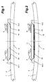
- Fig. 1 shows a side view of a section of a ski 1 at rest, the bottom 3 in the area of Binding is arched.
- the device On the top 2 of the ski 1 is a device mounted, with the help of which it is possible to adjust the distance between ski 1 and binding 8, 9 or boot (not shown) to change while driving.
- the device consists of a front and a rear fixed part 10.1, 10.2.
- a lifting plate 11 sits between the two 10.1, 10.2 and the lifting plate 11 have each other corresponding wedge-shaped sliding surfaces 23, so are oriented that the lifting plate 11 can be raised.
- Fig. 2 shows the state that occurs when cornering with edge grip. Since the Ski 1 is about its neutral zone bends, the top of the ski shortens 2. The Distance between the two fixed parts 10.1, 10.2 shortened also and the lifting plate 11 slips the sliding surfaces 23 high. As desired for cornering you get this way a large distance between ski 1 and ski binding or Shoe.
- the elastic intermediate layer 19 fills the gap Lift plate 11 and ski surface 2 and prevents that Ingress of ice and snow.
- FIG 3 and 5 show a side view and a top view Fixed part 10.3, FIGS. 4 and 6 as a side view and Top view of the end section of a matching lifting plate 11.
- the fixed part 10 is initially with three holes 20 equipped for mounting on the ski 1. It has one centric spring 21 and one each on the right and left wedge-shaped sliding surface 23.
- the end of the spring 21 is also designed as a sliding surface 25. Besides, that is End 22 of the spring 21 widened like a dovetail.
- the matching end of the lifting plate 11 has a groove 31 and with sliding surfaces 33, 35 and the dovetail 22 matching undercut 32 equipped.
- the corresponding sliding surfaces 23, 33; 25, 35 do that Raising the lifting plate 11, groove 31 and spring 21 cause the Transfer of forces when edging the ski 1 and the Dovetail connection 22, 32 holds the lifting plate 11 captive on the fixed part 10.
- FIG. 7 to 10 show an alternative embodiment of Fixed part 10.4 and lifting plate 11.
- Fixed part 10.4 with the groove 51
- the lifting plate 11 with the spring 41 equipped.
- An elongated hole 44 is in the spring 41 incorporated, which is parallel to the sliding surfaces 43, 45 extends.
- Through the legs 56 next to the groove 51 introduced a transverse bore 54.
- a retaining pin (not shown) inserted fixed part 10.4 and lifting plate 11 are captive connected.
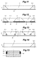
- FIG. 11 again shows that already in FIGS. 1 and 2 shown three-part lifting device, consisting of two Fixed parts 10.1, 10.2 and a lifting plate 11. Between the Ski surface 2 and the fixed parts 10.1, 10.2 and the Lift plate 11 is a continuous elastic Intermediate layer 18.
- Fig. 12 shows one of three fixed parts 10.1, 10.2, 12 and two lifting plates 11.1, 11.2 existing variant. Between the Ski surface 2 and the fixed parts 10.1, 10.2, 12 is located an elastic intermediate layer 17, preferably greater hardness. Between the ski surface 2 and the There is also a lifting plate 11.1, 11.2 elastic intermediate layer 19 of other hardness.
- Fig. 13 shows a six-part lifting device, consisting from four fixed parts 10.1, 10.2, 13.1, 13.2 and two Lifting plates 11.1, 11.2.
- the two middle fixed parts 13.1, 13.2 are spaced apart.
- Between ski surface 2 and the fixed parts or the lifting plates is one elastic intermediate layer 16 of greater thickness.
- intermediate layer 16 is in one piece and connects the two separate lifting devices.
- the two Lifting devices with different wedge angles a, b be equipped.
- the one on the left in the drawing Lifting device has steep wedge angles a, which in the Drawing right lifting device, however, flatter wedge angles b.
- the lengths of the two lifting plates 11.1, 11.2 different. In this way, the lifting plates 11.1, 11.2 different heights with the same ski curvature raised.
- Fig. 14 finally shows a two-part only Lifting device, consisting of a fixed part 10.2 and one Lifting plate 14.
- the lifting plate 14 is on its from the fixed part 10.2 spaced end directly connected to the ski 1.
- Fixed part 10.2 and lifting plate 14 are omitted because these forces of the lifting plate 14 can be transferred directly into the ski 1.
- the lifting plate 14 is not so rigid can be as in the previously described cases, but must have a certain elasticity to the stroke enable.
- ski 15 shows a cross section through ski 1, lifting plate 11 and intermediate layer 19.
- the lifting plate 11 must also be covered on the ski 1 11 protective strips 60 to the right and left of the lifting plate assembled. These are made from an elastic material not to disturb the even bending line of the ski.
Abstract
Description
Die Erfindung betrifft Vorrichtungen zum Montieren einer
Skibindung auf einem Ski gemäß dem Oberbegriff des Anspruchs
1.The invention relates to devices for mounting a
Ski binding on a ski according to the preamble of the
Skier sowohl für den Abfahrtslauf als auch für den Langlauf werden so gefertigt, daß sie im mittleren Bereich, wo die Skibindung montiert wird, konvex gewölbt sind. Diese Längswölbung verschwindet unter dem Einfluß des Gewichts des Skiläufers. Gleichzeitig werden Skispitze und Skienden mit entsprechenden Kräften in den Schnee gedrückt. Dadurch bekommt der Ski guten Kontakt zum Schnee, hält die Spur gut, flattert nicht beim Fahren usw. Allerdings behindert diese Längswölbung das Drehen des Skis; der Skiläufer muß gegebenenfalls mittels aktiver Hoch- oder Tiefentlastung das Drehen der Skier verbessern.Skis for both downhill and cross-country skiing are manufactured so that they are in the middle area, where the Ski binding is mounted, are convex. This Longitudinal curvature disappears under the influence of the weight of the Skier. At the same time, the ski tip and ski tips become corresponding forces in the snow. Thereby the ski gets good contact with the snow, keeps the track well, does not flutter when driving etc. However, this hinders Longitudinal curvature turning the ski; the skier must if necessary, by means of active high or low relief Improve turning of the skis.
Ein weiterer Nachteil der konvexen Längswölbung ist, daß sie das Befahren von Kurven, insbesondere mit Kantengriff, behindert, da die natürliche Längswölbung der Skier der beim Kurvenfahren erforderlichen Wölbung genau entgegengesetzt ist. In neuerer Zeit werden daher bevorzugt stark taillierte Skier, sogenannte Carver-Skier, verwendet, die im Bereich von Spitze und Ende erheblich breiter sind als im Bereich der Bindung. Je stärker diese Taillierung, desto engere Kurven lassen sich auf der Kante befahren.Another disadvantage of the convex longitudinal curvature is that it driving on curves, especially with edge grip, hindered because the natural longitudinal curvature of the skis when The curvature required for cornering is exactly the opposite is. In recent times, therefore, strongly waisted are preferred Skis, so-called carver skis, are used in the area from the top and end are considerably wider than in the area the bond. The stronger this waist, the tighter Curves can be driven on the edge.
Es ist gängige Praxis, die Skibindung an einer Zwischenplatte zu montieren, die ihrerseits mit Abstand zum Ski montiert wird. Dies ist beispielsweise beschrieben in der DE-A 41 00 327 oder der DE-A 43 18 513. Diese bekannten Zwischenplatten haben in erster Linie die Aufgabe zu verhindern, daß der Skischuh beim Kanten der Skier den Schnee berührt. In zweiter Linie beabsichtigen diese bekannten Vorrichtungen, die Zwischentragplatte, die wegen der sicheren Auslösung der Skibindung bei Stürzen usw. starr sein muß, vom Ski zu entkoppeln, damit dieser seine natürliche Elastizität behalten kann. Die Vorrichtung gemäß DE-A 41 00 327 beabsichtigt des weiteren, die Punkte, an denen die Kräfte zwischen Skiläufer bzw. Skibindung und Ski übertragen werden, unabhängig von der Schuhgröße positionieren zu können.It is common practice to ski bind to one To mount intermediate plate, which in turn is at a distance from the Ski is mounted. This is described, for example, in DE-A 41 00 327 or DE-A 43 18 513. These known Intermediate plates have the primary task prevent the ski boot from bending the skis Snow touches. In the second place, they intend known devices, the intermediate support plate, because of rigid triggering of the ski binding in the event of falls etc. must be decoupled from the ski so that it is his can retain natural elasticity. The device according to DE-A 41 00 327 further intends to include the points the forces between skiers or ski bindings and skis be transferred regardless of shoe size to be able to position.
Schließlich ist aus der WO-A 95/32035 eine Hebelkonstruktion bekannt, mit deren Hilfe die Längswölbung des Skis während des Fahrens aktiv verändert werden kann.Finally, WO-A 95/32035 is a lever construction known, with the help of the longitudinal curvature of the ski during driving can be actively changed.
Während beim Befahren von Kurven, insbesondere von engen Kurven mit Kantengriff, ein großer Abstand zwischen Ski und Bindung bzw. Schuh von Vorteil ist, hat sich herausgestellt, daß beim Gleiten, d. h. beim Befahren von geraden Strecken ohne Kantengriff, der Abstand zwischen Ski und Bindung bzw. Schuh möglichst gering sein sollte, um eine optimale Fahrt zu erzielen. Nach dem Stand der Technik lassen sich diese beiden entgegengesetzten Bedingungen jedoch nicht unter einen Hut bringen; jede Bindungsmontage stellt daher lediglich einen mehr oder weniger guten Kompromiß dar.While driving around bends, especially narrow ones Curves with edge grip, a large distance between the ski and Binding or shoe is advantageous, it turned out that when sliding, d. H. when driving on straight lines without edge grip, the distance between ski and binding or Shoe should be as low as possible to get the best ride to achieve. According to the state of the art, these can be but not under the two opposite conditions bring a hat; every binding assembly therefore poses just a more or less good compromise.
Der vorliegenden Erfindung liegt die Aufgabe zugrunde, eine Vorrichtung anzugeben, mit deren Hilfe der Abstand zwischen Ski und Bindung bzw. Schuh während der Fahrt verändert werden kann und dennoch eine gleichmäßige Biegelinie des Skis gewährleistet wird.The present invention has for its object a Specify the device by means of which the distance between Skis and bindings or shoes changed while driving can be and yet a uniform bending line of the Skis is guaranteed.
Diese Aufgabe wird gelöst durch eine Vorrichtung mit den
Merkmalen des Anspruchs 1.This object is achieved by a device with the
Features of
Dank der erfindungsgemäßen Konstruktion verändert sich der Abstand zwischen Ski und Hubplatte bzw. Bindung bzw. Schuh beim Befahren von Kurven, und zwar um so mehr, je enger die Kurve ist. Je mehr sich der Ski durchbiegt, desto größer weiter entfernt sich die Hubplatte vom Ski. Im übrigen läßt sich der Hub auch gezielt beeinflussen durch die Länge der Hubplatte und das Übersetzungsverhältnis des Getriebes, welches die Krümmung des Skis bzw. die dadurch eintretende Verkürzung der Skioberseite in den Hub umwandelt. Die erfindungsgemäße Konstruktion ist bei jedem Ski nachrüstbar. Auch Skirennläufer können von der vorliegenden Erfindung sehr profitieren, da erstmals die Möglichkeit besteht, den Abstand zwischen Ski und Bindung bzw. Schuh dynamisch an die jeweilige Fahrsituation anzupassen.Thanks to the construction according to the invention, the Distance between ski and lifting plate or binding or boot when cornering, and the more the narrower the Curve is. The more the ski bends, the bigger the lift plate moves further away from the ski. Otherwise leaves the stroke can also be influenced by the length of the Lifting plate and the gear ratio of the transmission, which is the curvature of the ski or the one entering it Shortening the top of the ski converts to the stroke. The Construction according to the invention can be retrofitted to any ski. Ski racers can also use the present invention benefit a lot, because for the first time it is possible to Distance between ski and binding or boot dynamically to the adapt each driving situation.
Als weiterer Vorteil wäre zu nennen, daß die die Skistiefel haltende Skibindung keinen eingebauten Längenausgleich mehr benötigt, was die Bindungskonstruktion vereinfacht und verbilligt und insbesondere das Auslöseverhalten bei Stürzen erheblich verbessert.Another advantage would be that the ski boots holding ski binding no longer built-in length compensation needed, which simplifies the binding construction and cheaper and especially the triggering behavior in the event of a fall significantly improved.
Der Maschinenbau kennt eine Reihe von Getrieben, die die Umsetzung einer Längenänderung in einen Hub ermöglichen. Eine besonders einfache und zuverlässige Konstruktion sind miteinander korrespondierende, keilförmige Gleitflächen an Fixteil und Hubplatte, die so orientiert sind, daß die Hubplatte beim Durchbiegen des Skis angehoben wird.Mechanical engineering knows a number of gears that the Enable implementation of a change in length in a hub. A particularly simple and reliable construction are corresponding wedge-shaped sliding surfaces Fixed part and lifting plate, which are oriented so that the Lifting plate is lifted when the ski bends.
Es versteht sich, daß die Hubplatte mit einer Führung ausgerüstet sein muß, die die beim Kanten des Skis entstehenden Kräfte sicher überträgt. Eine bevorzugte Realisierung ist eine Nut-Feder-Verbindung zwischen Hubplatte und Ski, insbesondere zwischen Hubplatte und Fixteil, wobei Nut und Feder sich bevorzugt in Längsrichtung des Skis erstrecken.It is understood that the lifting plate with a guide must be equipped with the edges of the ski emerging forces safely transmits. A preferred one Realization is a tongue and groove connection between Lift plate and ski, especially between lift plate and Fixed part, tongue and groove preferably in the longitudinal direction of the ski.
Um im Falle einer Nut-Feder-Verbindung die Hubplatte am Fixteil beweglich, jedoch unverlierbar befestigen zu können, ist gemäß einer Weiterbildung der Erfindung in die die Nut begrenzenden Schenkel eine Querbohrung, in die Feder ein Langloch eingebracht. Das Langloch erstreckt sich parallel zu den Gleitflächen. Ein durch Querbohrung und Langloch gesteckter Haltestift vervollständigt die Verbindung.In the case of a tongue and groove connection, the lifting plate on Fixed part can be moved, but cannot be lost, is according to a development of the invention in the groove limiting leg a cross hole in the spring Elongated hole introduced. The elongated hole extends parallel to the sliding surfaces. One through cross hole and slot inserted holding pin completes the connection.
Gemäß einer alternativen Ausgestaltung kann zwischen Fixteil und Hubplatte eine Schwalbenschwanz-Verbindung vorgesehen werden. Diese überträgt die Kräfte beim Kanten des Skis und fixiert die Hubplatte unverlierbar am Fixteil.According to an alternative embodiment, there can be a fixed part and lifting plate provided a dovetail connection will. This transmits the forces when edging the ski and fixes the lifting plate captively on the fixed part.
Gegebenenfalls können alle Gleitflächen mit einer Schicht mit niedrigem Reibkoeffizienten belegt sein, z. B. mit einer Schicht aus Polytetrafluorethylen.If necessary, all sliding surfaces with one layer be occupied with a low coefficient of friction, e.g. B. with a Polytetrafluoroethylene layer.
Gemäß einer bevorzugten Weiterbildung der Erfindung befindet sich zwischen Ski und Hubplatte und/oder Fixteil wenigstens eine Zwischenschicht aus einem elastischen Material. Diese Zwischenschicht hat zunächst einmal die Aufgabe, Beschädigungen der Skioberfläche zu verhindern. Die Hauptaufgabe besteht darin, den beim Heben der Hubplatte entstehenden Spalt zwischen Hubplatte und Ski zu verschließen, um das Eindringen von Eis und Schnee zu verhindern. Schließlich kann diese elastische Zwischenschicht auch als Feder eingesetzt werden, um die Hubplatte von einem Teil des Gewichts des Skifahrers zu entlasten.According to a preferred development of the invention between ski and lift plate and / or fixed part at least an intermediate layer made of an elastic material. This First of all, the intermediate layer has the task To prevent damage to the ski surface. The The main task is to lift the lifting plate resulting gap between the lifting plate and the ski seal to prevent the ingress of ice and snow prevent. Finally, this can be elastic Intermediate layer can also be used as a spring to the Lift plate by part of the weight of the skier too relieve.
Die elastische Zwischenschicht kann aus unterschiedlichen Materialien bestehen, beispielsweise unter dem Fixteil härter und/oder dünner und unter der Hubplatte weicher und/oder dicker gemacht werden. Auch kann die Zwischenschicht selbst aus mehreren Schichten zusammengesetzt sein.The elastic intermediate layer can consist of different Materials exist, for example under the fixed part harder and / or thinner and softer under the lifting plate and / or be made thicker. It can also Intermediate layer itself consisting of several layers be composed.
Um die Bewegungen der Hubplatte zu dämpfen, kann die elastische Zwischenschicht ebenfalls eingesetzt werden. To dampen the movements of the lifting plate, the elastic intermediate layer can also be used.
Darüber hinaus besteht die Möglichkeit, eine Dämpfungsschicht, z. B. aus Gummi, in das Langloch zu integrieren, wo es die Bewegung des Haltestifts bremst.There is also the possibility of a Damping layer, e.g. B. made of rubber, in the slot integrate where it slows down the movement of the retaining pin.
Gemäß einer ersten Alternative bestehen Fixteil und/oder Hubplatte aus faserverstärktem Kunststoff. Alternativ dazu können Fixteil und/oder Hubplatte aber auch aus Metall bestehen, beispielsweise einer Leichtmetallegierung oder einer Titanlegierung.According to a first alternative, there are fixed parts and / or Lifting plate made of fiber-reinforced plastic. Alternatively can also be a fixed part and / or lifting plate made of metal exist, for example a light metal alloy or a titanium alloy.
Während das Fixteil in aller Regel möglichst starr ausgebildet wird, kann die Hubplatte bei Bedarf auch weniger starr ausgebildet sein. Auch auf diese Weise läßt sich die Abhängigkeit zwischen Krümmung des Skis und Hubhöhe beeinflussen. In aller Regel wird jedoch auch die Hubplatte starr ausgeführt.While the fixed part is usually as rigid as possible is formed, the lifting plate can also less if necessary be rigid. In this way, too Dependency between ski curvature and lifting height influence. As a rule, however, the lifting plate rigidly executed.
Wie schon erwähnt, können die Fixteile nachträglich auf jeden handelsüblichen Ski montiert werden. Alternativ dazu besteht jedoch die Möglichkeit, die Fixteile gleich bei der Produktion in den Ski oder in die Bindung zu integrieren.As already mentioned, the fixed parts can be retrofitted every standard ski can be mounted. Alternatively However, there is the possibility of the fixed parts at the same time Integrate production into the ski or into the binding.
Schließlich besteht auch die Möglichkeit, zwei Hubplatten zu verwenden und das Vorderteil und das Hinterteil der Skibindung auf je einer Hubplatte zu montieren. In diesem Fall besteht die Möglichkeit, durch abweichende Keilwinkel und/oder Längen der beiden Hubplatten einen unterschiedlichen Hub zu realisieren, beispielsweise um die Ferse des Skiläufers beim Befahren von Kurven stärker anzuheben.Finally, there is also the possibility of two lifting plates use and the front and rear of the Mount ski binding on one lifting plate each. In this Case there is the possibility of deviating wedge angles and / or lengths of the two lifting plates to realize different stroke, for example in order to Skier's heel stronger when cornering to raise.
Anhand der Zeichnung soll die Erfindung in Form von Ausführungsbeispielen näher erläutert werden. Es zeigen jeweils rein schematisch
- Fig. 1
- einen zentralen Ausschnitt eines Skis in Ruhestellung als Seitenansicht,
- Fig. 2
- den Ausschnitt der Fig. 1, jedoch bei gekrümmtem Ski,
- Fig. 3
- ein erstes Fixteil in Seitenansicht,
- Fig. 4
- einen dazu passenden Endabschnitt einer ersten Hubplatte in Seitenansicht,
- Fig. 5
- eine Draufsicht auf das Fixteil der Fig. 3,
- Fig. 6
- eine Draufsicht auf die Hubplatte der Fig. 4,
- Fig. 7
- ein zweites Fixteil in Seitenansicht,
- Fig. 8
- einen dazu passenden Endabschnitt einer zweiten Hubplatte in Seitenansicht,
- Fig. 9
- eine Draufsicht auf das Fixteil der Fig. 7,
- Fig. 10
- eine Draufsicht auf die Hubplatte der Fig. 8,
- Fig. 11
- eine dreiteilige Hubvorrichtung in Seitenansicht,
- Fig. 12
- eine fünfteilige Hubvorrichtung in Seitenansicht,
- Fig. 13
- eine sechsteilige Hubvorrichtung in Seitenansicht,
- Fig. 14
- eine zweiteilige Hubvorrichtung in Seitenansicht und
- Fig. 15
- einen Querschnitt durch einen Ski mit einer alternativen Hubvorrichtung.
- Fig. 1
- a central section of a ski in the rest position as a side view,
- Fig. 2
- 1, but with a curved ski,
- Fig. 3
- a first fixed part in side view,
- Fig. 4
- a matching end section of a first lifting plate in side view,
- Fig. 5
- 3 shows a plan view of the fixed part of FIG. 3,
- Fig. 6
- a plan view of the lifting plate of FIG. 4,
- Fig. 7
- a second fixed part in side view,
- Fig. 8
- a matching end section of a second lifting plate in side view,
- Fig. 9
- 7 shows a plan view of the fixed part of FIG. 7,
- Fig. 10
- 8 shows a plan view of the lifting plate of FIG. 8,
- Fig. 11
- a three-part lifting device in side view,
- Fig. 12
- a five-part lifting device in side view,
- Fig. 13
- a six-part lifting device in side view,
- Fig. 14
- a two-part lifting device in side view and
- Fig. 15
- a cross section through a ski with an alternative lifting device.
Fig. 1 zeigt in Seitenansicht einen Ausschnitt aus einem Ski
1 in Ruhestellung, dessen Unterseite 3 im Bereich der
Bindung gewölbt ist.Fig. 1 shows a side view of a section of a
Auf der Oberseite 2 des Skis 1 ist eine Vorrichtung
montiert, mit deren Hilfe es möglich ist, den Abstand
zwischen Ski 1 und Bindung 8, 9 bzw. Schuh (nicht
dargestellt) während der Fahrt zu verändern. Die Vorrichtung
besteht aus einem vorderen und einem hinteren Fixteil 10.1,
10.2. Zwischen beiden sitzt eine Hubplatte 11. Die Fixteile
10.1, 10.2 und die Hubplatte 11 besitzen miteinander
korrespondierende, keilförmige Gleitflächen 23, die so
orientiert sind, daß die Hubplatte 11 angehoben werden kann.On the
Zwischen Hubplatte 11 und Skioberseite 2 befindet sich eine
elastische Zwischenschicht 19.There is a between the lifting
Fig. 2 zeigt den Zustand, der sich beim Befahren von Kurven
mit Kantengriff einstellt. Da sich der Ski 1 um seine
neutrale Zone biegt, verkürzt sich die Skioberseite 2. Der
Abstand zwischen den beiden Fixteilen 10.1, 10.2 verkürzt
sich ebenfalls und die Hubplatte 11 rutscht die Gleitflächen
23 hoch. Wie für die Kurvenfahrt gewünscht erhält man so
einen großen Abstand zwischen Ski 1 und Skibindung bzw.
Schuh.Fig. 2 shows the state that occurs when cornering
with edge grip. Since the
Die elastische Zwischenschicht 19 füllt den Spalt zwischen
Hubplatte 11 und Skioberfläche 2 aus und verhindert das
Eindringen von Eis und Schnee.The elastic
Der Maschinenbau kennt eine Reihe von Getrieben, die
geeignet sind, die Verkürzung des Abstandes zwischen den
Fixteilen 10.1, 10.2 in einen Hub der Hubplatte 11
umzusetzen. Eine sehr einfache und zuverlässige Ausführung
sind die in den Fig. 1 und 2 schon beschriebenen
Keilflächen. Keilflächen sind jedoch noch nicht geeignet,
die beim Kanten der Skier entstehenden Kräfte zu übertragen;
hierzu sind besondere Einrichtungen erforderlich. Des
weiteren sind besondere Einrichtungen erforderlich, die
verhindern, daß Fixteile 10.1, 10.2 und Hubplatte 11 sich
voneinander lösen. Anhand der Fig. 3 bis 6 und 7 bis 10
sollen zwei Ausführungsbeispiele erläutert werden, die diese
Funktionen erfüllen.Mechanical engineering knows a number of gears that
are suitable to shorten the distance between the
Fixed parts 10.1, 10.2 in one stroke of the lifting
Die Fig. 3 und 5 zeigen als Seitenansicht und Draufsicht ein
Fixteil 10.3, die Fig. 4 und 6 als Seitenansicht und
Draufsicht den Endabschnitt einer dazu passenden Hubplatte
11. Das Fixteil 10 ist zunächst mit drei Bohrungen 20
ausgerüstet für die Montage auf dem Ski 1. Es besitzt eine
zentrische Feder 21 und rechts und links davon je eine
keilförmige Gleitfläche 23. Das Ende der Feder 21 ist
ebenfalls als Gleitfläche 25 ausgebildet. Außerdem ist das
Ende 22 der Feder 21 schwalbenschwanzartig verbreitert.3 and 5 show a side view and a top view
Fixed part 10.3, FIGS. 4 and 6 as a side view and
Top view of the end section of a
Das dazu passende Ende der Hubplatte 11 ist mit einer Nut 31
sowie mit Gleitflächen 33, 35 sowie der zum Schwalbenschwanz
22 passenden Hinterschneidung 32 ausgerüstet. Die
korrespondierenden Gleitflächen 23, 33; 25, 35 bewirken das
Anheben der Hubplatte 11, Nut 31 und Feder 21 bewirken die
Übertragung der Kräfte beim Kanten des Skis 1 und die
Schwalbenschwanzverbindung 22, 32 hält die Hubplatte 11
unverlierbar am Fixteil 10.The matching end of the lifting
Die Fig. 7 bis 10 zeigen eine alternative Ausgestaltung von
Fixteil 10.4 und Hubplatte 11. In diesem Fall ist das
Fixteil 10.4 mit der Nut 51, die Hubplatte 11 mit der Feder
41 ausgerüstet. In die Feder 41 ist ein Langloch 44
eingearbeitet, welches sich parallel zu den Gleitflächen 43,
45 erstreckt. Durch die Schenkel 56 neben der Nut 51 ist
eine Querbohrung 54 eingebracht. Sobald durch Querbohrung 54
und Langloch 44 ein Haltestift (nicht dargestellt) gesteckt
ist, sind Fixteil 10.4 und Hubplatte 11 unverlierbar
verbunden. 7 to 10 show an alternative embodiment of
Fixed part 10.4 and lifting
Wie Fig. 8 zeigt, ist in das Langloch 44 eine
Dämpfungsschicht 46, beispielsweise aus Gummi, integriert,
die mit dem Haltestift zusammenwirkt und die Bewegungen der
Hubplatte 11 dämpft.8 shows, is in the
Es versteht sich, daß alle Gleitflächen, nicht nur die Keilflächen 23, 25; 33, 35; 43, 53; 45, 55, mit einer die Reibung herabsetzenden Schicht, beispielsweise aus Polytetrafluorethylen, beschichtet sein können.It goes without saying that all sliding surfaces, not just those Wedge surfaces 23, 25; 33, 35; 43, 53; 45, 55, with a die Friction reducing layer, for example Polytetrafluoroethylene, can be coated.
Anhand der Fig. 11 bis 14 sollen verschiedene Weiterbildungen der erfindungsgemäßen Hubvorrichtung erläutert werden.11 to 14 different Developments of the lifting device according to the invention are explained.
Fig. 11 zeigt nochmals die bereits in den Fig. 1 und 2
dargestellte dreiteilige Hubvorrichtung, bestehend aus zwei
Fixteilen 10.1, 10.2 und einer Hubplatte 11. Zwischen der
Skioberfläche 2 und den Fixteilen 10.1, 10.2 sowie der
Hubplatte 11 befindet sich eine durchgehende elastische
Zwischenschicht 18.FIG. 11 again shows that already in FIGS. 1 and 2
shown three-part lifting device, consisting of two
Fixed parts 10.1, 10.2 and a lifting
Fig. 12 zeigt eine aus drei Fixteilen 10.1, 10.2, 12 und
zwei Hubplatten 11.1, 11.2 bestehende Variante. Zwischen der
Skioberfläche 2 und den Fixteilen 10.1, 10.2, 12 befindet
sich eine elastische Zwischenschicht 17, vorzugsweise
größerer Härte. Zwischen der Skioberfläche 2 und den
Hubplatten 11.1, 11.2 befindet sich ebenfalls eine
elastische Zwischenschicht 19 anderer Härte.Fig. 12 shows one of three fixed parts 10.1, 10.2, 12 and
two lifting plates 11.1, 11.2 existing variant. Between the
Fig. 13 zeigt eine sechsteilige Hubvorrichtung, bestehend
aus vier Fixteilen 10.1, 10.2, 13.1, 13.2 und zwei
Hubplatten 11.1, 11.2. Die beiden mittleren Fixteile 13.1,
13.2 sind gegenseitig beabstandet. Zwischen Skioberfläche 2
und den Fixteilen bzw. den Hubplatten befindet sich eine
elastische Zwischenschicht 16 größerer Dicke. Die
Zwischenschicht 16 ist in diesem Fall einteilig und
verbindet die beiden getrennten Hubvorrichtungen.Fig. 13 shows a six-part lifting device, consisting
from four fixed parts 10.1, 10.2, 13.1, 13.2 and two
Lifting plates 11.1, 11.2. The two middle fixed parts 13.1,
13.2 are spaced apart. Between
Wie dieses Ausführungsbeispiel zeigt, können die beiden Hubvorrichtungen mit unterschiedlichen Keilwinkeln a, b ausgerüstet werden. Die in der Zeichnung linke Hubvorrichtung besitzt steile Keilwinkel a, die in der Zeichnung rechte Hubvorrichtung dagegen flachere Keilwinkel b. Außerdem sind auch die Längen der beiden Hubplatten 11.1, 11.2 unterschiedlich. Auf diese Weise werden die Hubplatten 11.1, 11.2 bei gleicher Skikrümmung unterschiedlich hoch gehoben.As this embodiment shows, the two Lifting devices with different wedge angles a, b be equipped. The one on the left in the drawing Lifting device has steep wedge angles a, which in the Drawing right lifting device, however, flatter wedge angles b. In addition, the lengths of the two lifting plates 11.1, 11.2 different. In this way, the lifting plates 11.1, 11.2 different heights with the same ski curvature raised.
Fig. 14 schießlich zeigt eine nur zweiteilige
Hubvorrichtung, bestehend aus einem Fixteil 10.2 und einer
Hubplatte 14. Die Hubplatte 14 ist an ihrem vom Fixteil 10.2
beabstandeten Ende direkt mit dem Ski 1 verbunden. Bei
dieser Konstruktion kann die Nut-Feder-Verbindung zwischen
Fixteil 10.2 und Hubplatte 14 entfallen, da diese Kräfte von
der Hubplatte 14 direkt in den Ski 1 übertragen werden. Es
versteht sich, daß bei dieser nur zweiteiligen
Ausführungsform die Hubplatte 14 nicht so starr ausgebildet
sein kann wie in den zuvor beschriebenen Fällen, sondern
eine gewisse Elastizität besitzen muß, um den Hub zu
ermöglichen.Fig. 14 finally shows a two-part only
Lifting device, consisting of a fixed part 10.2 and one
Fig. 15 zeigt einen Querschnitt durch Ski 1, Hubplatte 11
und Zwischenschicht 19. Um den Spalt zwischen Ski 1 und
Hubplatte 11 zusätzlich abzudecken, sind auf dem Ski 1
rechts und links neben der Hubplatte 11 Schutzleisten 60
montiert. Diese bestehen aus einem elastischen Material, um
die gleichmäßige Biegelinie des Skis nicht zu stören.15 shows a cross section through
Claims (16)
Applications Claiming Priority (2)
| Application Number | Priority Date | Filing Date | Title |
|---|---|---|---|
| DE19704959 | 1997-02-10 | ||
| DE1997104959 DE19704959A1 (en) | 1997-02-10 | 1997-02-10 | Device for mounting a ski binding |
Publications (2)
| Publication Number | Publication Date |
|---|---|
| EP0857500A2 true EP0857500A2 (en) | 1998-08-12 |
| EP0857500A3 EP0857500A3 (en) | 1999-10-13 |
Family
ID=7819801
Family Applications (1)
| Application Number | Title | Priority Date | Filing Date |
|---|---|---|---|
| EP98101794A Withdrawn EP0857500A3 (en) | 1997-02-10 | 1998-02-03 | Device for mounting a ski binding |
Country Status (2)
| Country | Link |
|---|---|
| EP (1) | EP0857500A3 (en) |
| DE (1) | DE19704959A1 (en) |
Cited By (5)
| Publication number | Priority date | Publication date | Assignee | Title |
|---|---|---|---|---|
| AT407838B (en) * | 1999-02-05 | 2001-06-25 | Kittler Reinhard Mag | Winter sport device |
| FR2812210A1 (en) | 2000-07-26 | 2002-02-01 | Rossignol Sa | Snowboard comprises platform able to move relative to snowboard upper face, one platform side inclined at angle to upper surface supported on inclined surface of outgrowth under force exerted by user's foot |
| EP1188464A1 (en) | 2000-09-15 | 2002-03-20 | Reinhard Mag. Kittler | Wintersport device |
| FR2838063A1 (en) * | 2002-04-09 | 2003-10-10 | Rossignol Sa | Alpine ski comprises longitudinal element extending to boot fixing device on each side of which is ramp and associated support element which acts against ramp surface when ski bends |
| WO2015150217A1 (en) * | 2014-04-02 | 2015-10-08 | Steinbach Alpin | Connection system for a sliding board |
Citations (3)
| Publication number | Priority date | Publication date | Assignee | Title |
|---|---|---|---|---|
| DE4100327A1 (en) | 1990-01-18 | 1991-07-25 | Salomon Sa | Assembly device for fitting boots on skis - has intermediate support plate resting freely on support element |
| DE4318513A1 (en) | 1993-06-03 | 1994-12-08 | Marker Deutschland Gmbh | Binding base plate |
| WO1995032035A1 (en) | 1994-05-21 | 1995-11-30 | Goetzfried Peter | Device for the adequate alteration of the longitudinal bow of a ski |
Family Cites Families (5)
| Publication number | Priority date | Publication date | Assignee | Title |
|---|---|---|---|---|
| AT401351B (en) * | 1988-09-30 | 1996-08-26 | Atomic Austria Gmbh | CONNECTING DEVICE FOR HOLDING A SKI BOOT ON A SKI |
| CH681205A5 (en) * | 1990-03-06 | 1993-02-15 | Varpat Patentverwertung | Ski-boot binding - has damper between coupling half and bearing plate hinging on ski |
| WO1995007737A1 (en) * | 1993-09-13 | 1995-03-23 | Marco Maggiolo | Device for improving the efficiency and controllability of skis |
| DE4442095A1 (en) * | 1994-11-25 | 1996-05-30 | Hans Meyer | Spring board for a ski |
| FR2742343B1 (en) * | 1995-12-19 | 1998-01-16 | Rossignol Sa | SLIDER BOARD EQUIPPED WITH A DEVICE INTENDED TO MODIFY THE STIFFNESS OF THE BOARD UNDER THE EFFECT OF A VERTICAL PUSH GIVEN BY THE USER |
-
1997
- 1997-02-10 DE DE1997104959 patent/DE19704959A1/en not_active Withdrawn
-
1998
- 1998-02-03 EP EP98101794A patent/EP0857500A3/en not_active Withdrawn
Patent Citations (3)
| Publication number | Priority date | Publication date | Assignee | Title |
|---|---|---|---|---|
| DE4100327A1 (en) | 1990-01-18 | 1991-07-25 | Salomon Sa | Assembly device for fitting boots on skis - has intermediate support plate resting freely on support element |
| DE4318513A1 (en) | 1993-06-03 | 1994-12-08 | Marker Deutschland Gmbh | Binding base plate |
| WO1995032035A1 (en) | 1994-05-21 | 1995-11-30 | Goetzfried Peter | Device for the adequate alteration of the longitudinal bow of a ski |
Cited By (7)
| Publication number | Priority date | Publication date | Assignee | Title |
|---|---|---|---|---|
| AT407838B (en) * | 1999-02-05 | 2001-06-25 | Kittler Reinhard Mag | Winter sport device |
| FR2812210A1 (en) | 2000-07-26 | 2002-02-01 | Rossignol Sa | Snowboard comprises platform able to move relative to snowboard upper face, one platform side inclined at angle to upper surface supported on inclined surface of outgrowth under force exerted by user's foot |
| EP1188464A1 (en) | 2000-09-15 | 2002-03-20 | Reinhard Mag. Kittler | Wintersport device |
| FR2838063A1 (en) * | 2002-04-09 | 2003-10-10 | Rossignol Sa | Alpine ski comprises longitudinal element extending to boot fixing device on each side of which is ramp and associated support element which acts against ramp surface when ski bends |
| WO2015150217A1 (en) * | 2014-04-02 | 2015-10-08 | Steinbach Alpin | Connection system for a sliding board |
| WO2015150227A1 (en) * | 2014-04-02 | 2015-10-08 | Steinbach Alpin | Damping system for glide board |
| AT14525U3 (en) * | 2014-04-02 | 2018-03-15 | Steinbach Alpin Brigitte Weber E U | Connection system for gliding board |
Also Published As
| Publication number | Publication date |
|---|---|
| EP0857500A3 (en) | 1999-10-13 |
| DE19704959A1 (en) | 1998-08-13 |
Similar Documents
| Publication | Publication Date | Title |
|---|---|---|
| DE3153703C2 (en) | Safety ski binding with heel and toe holders | |
| DE3742918A1 (en) | ALPINE SKI SHOE | |
| DE3934891A1 (en) | DAMPING DEVICE FOR SHOCK AND VIBRATION BETWEEN A SKI AND THE BINDING OF THE SHOE | |
| DD238726A5 (en) | GUIDANCE APPARATUS OF A SHOE, AND SHOE AND SURFACE ADJUSTED TO THIS DEVICE | |
| CH619147A5 (en) | ||
| DE3934888A1 (en) | Shock damping for skis - by mounting fixing screws for binding in plugs of viscoelastic material | |
| AT405610B (en) | COMPOSITE PLATE FOR MOUNTING A BINDING FOR A SHOE ON AN ALPINSKI | |
| CH658602A5 (en) | MULTI-LAYER SKI IN SANDWICH DESIGN. | |
| EP0151975B1 (en) | Ski de fond | |
| DE1943989A1 (en) | Low-friction support device for ski boots on skis | |
| AT409935B (en) | DISTRIBUTION DEVICE FOR LOADS AND / OR FORCES TO BE TRANSFERRED TO A SPORTS EQUIPMENT | |
| EP2409741B1 (en) | Glide board with reversed camber, so-called rocker | |
| DE3633098C2 (en) | ||
| DD239338A5 (en) | SIDE GUIDE DEVICE OF AN SKI SHOE, AND TO THIS DEVICE ATTACHED SHOE AND CROSS-COAST SKI | |
| DE3115618A1 (en) | Supporting unit for a cross-country ski boot on a ski | |
| EP0857500A2 (en) | Device for mounting a ski binding | |
| DE4020212C3 (en) | Ski, especially alpine skiing | |
| DE3929352A1 (en) | LATERAL GUIDE DEVICE OF A SKI SHOE | |
| EP0760704B1 (en) | Device for the adequate alteration of the longitudinal bow of a ski | |
| DE4030214C2 (en) | Lateral guide device of a cross-country ski boot | |
| DE3315641C2 (en) | ||
| AT505714B1 (en) | SNOWBOARD WITH TIE | |
| EP0935489B1 (en) | Device for modifying the lateral bending of a ski boot | |
| EP1615706B1 (en) | Snowboard | |
| EP2821114B1 (en) | Safety ski binding system |
Legal Events
| Date | Code | Title | Description |
|---|---|---|---|
| PUAI | Public reference made under article 153(3) epc to a published international application that has entered the european phase |
Free format text: ORIGINAL CODE: 0009012 |
|
| AK | Designated contracting states |
Kind code of ref document: A2 Designated state(s): AT BE CH DE DK ES FI FR GB GR IE IT LI LU MC NL PT SE |
|
| AX | Request for extension of the european patent |
Free format text: AL;LT;LV;MK;RO;SI |
|
| PUAL | Search report despatched |
Free format text: ORIGINAL CODE: 0009013 |
|
| AK | Designated contracting states |
Kind code of ref document: A3 Designated state(s): AT BE CH DE DK ES FI FR GB GR IE IT LI LU MC NL PT SE |
|
| AX | Request for extension of the european patent |
Free format text: AL;LT;LV;MK;RO;SI |
|
| RIC1 | Information provided on ipc code assigned before grant |
Free format text: 6A 63C 9/00 A, 6A 63C 5/075 B |
|
| AKX | Designation fees paid | ||
| REG | Reference to a national code |
Ref country code: DE Ref legal event code: 8566 |
|
| STAA | Information on the status of an ep patent application or granted ep patent |
Free format text: STATUS: THE APPLICATION IS DEEMED TO BE WITHDRAWN |
|
| 18D | Application deemed to be withdrawn |
Effective date: 20000414 |